

Page 1

SmartSwitch 2200 Series
(2E253, 2H252, 2H253, and 2H258)
Standalone Switches
Local Management User’s Guide
9033650-04
Page 2

Page 3

NOTICE
Enterasys Networks reserves the right to make changes in specifications and other information contained in this
document and its web site without prior notice. The reader should in all cases consult Enterasys Networks to determine
whether any such changes have been made.
The hardware, firmware, or software described in this document is subject to change without notice.
IN NO EVENT SHALL ENTERASYS NETWORKS BE LIABLE FOR ANY INCIDENTAL, INDIRECT, SPECIAL,
OR CONSEQUENTIAL DAMAGES WHATSOEVER (INCLUDING BUT NOT LIMITED TO LOST PROFITS)
ARISING OUT OF OR RELATED TO THIS DOCUMENT, WEB SITE, OR THE INFORMATION CONTAINED IN
THEM, EVEN IF ENTERASYS NETWORKS HAS BEEN ADVISED OF , KNEW OF, OR SHOULD HA VE KNO WN
OF, THE POSSIBILITY OF SUCH DAMAGES.
Enterasys Networks, Inc.
50 Minuteman Road
Andover , MA 01810
2003 Enterasys Networks, Inc. All rights reserved.
Printed in the United States of America.
Part Number: 9033650-04 June 2003
ENTERASYS NETWORKS, NETSIGHT, SMARTSWITCH and LANVIEW are registered trademarks and
ENTERASYS MATRIX, MATRIX, WEBVIEW, and any logos associated therewith, are trademarks of Enterasys
Networks, Inc. in the United States and other countries.
All other product names mentioned in this manual may be trademarks or registered trademarks of their respective
companies.
Version: Information in this guide refers to SmartSwitch 2200 Series
firmware version 5.05.xx.
Page 4

ENTERASYS NETWORKS, INC.
PROGRAM LICENSE AGREEMENT
BEFORE OPENING OR UTILIZING THE ENCLOSED PRODUCT,
CAREFULLY READ THIS LICENSE AGREEMENT.
This document is an agreement (“Agreement”) between the end user (“You”) and Enterasys Networks, Inc. on behalf of
itself and its Affiliates (as hereinafter defined) (“Enterasys”) that sets forth Your rights and obligations with respect to
the Enterasys software program (including any accompanying documentation, hardware or media) (“Program”) in the
package and prevails over any additional, conflicting or inconsistent terms and conditions appearing on any purchase
order or other document submitted by You. “Affiliate” means any person, partnership, corporation, limited liability
company, or other form of enterprise that directly or indirectly through one or more intermediaries, controls, or is
controlled by, or is under common control with the party specified. This Agreement constitutes the entire understanding
between the parties, and supersedes all prior discussions, representations, understandings or agreements, whether oral or
in writing, between the parties with respect to the subject matter of this Agreement. The Program may be contained in
firmware, chips or other media.
BY INST ALLING OR O THER WISE USING THE PR OGRAM, YOU REPRESENT THAT YOU ARE A UTHORIZED
TO ACCEPT THESE TERMS ON BEHALF OF THE END USER (IF THE END USER IS AN ENTITY ON WHOSE
BEHALF YOU ARE AUTHORIZED TO ACT, “YOU” AND “YOUR” SHALL BE DEEMED TO REFER TO SUCH
ENTITY) AND THAT YOU AGREE THAT YOU ARE BOUND BY THE TERMS OF THIS AGREEMENT, WHICH
INCLUDES, AMONG OTHER PROVISIONS, THE LICENSE, THE DISCLAIMER OF WARRANTY AND THE
LIMITATION OF LIABILITY. IF YOU DO NOT AGREE TO THE TERMS OF THIS AGREEMENT OR ARE NOT
AUTHORIZED TO ENTER INTO THIS AGREEMENT, ENTERASYS IS UNWILLING TO LICENSE THE
PROGRAM TO Y OU AND YOU AGREE TO RETURN THE UNOPENED PRODUCT TO ENTERASYS OR YOUR
DEALER, IF ANY, WITHIN TEN (10) DAYS FOLLOWING THE DATE OF RECEIPT FOR A FULL REFUND.
IF YOU HAVE ANY QUESTIONS ABOUT THIS AGREEMENT, CONTACT ENTERASYS NETWORKS, LEGAL
DEPARTMENT AT (603) 332-9400.
You and Enterasys agree as follows:
1. LICENSE. You have the non-exclusive and non-transferable right to use only the one (1) copy of the Program
provided in this package subject to the terms and conditions of this Agreement.
2. RESTRICTIONS. Except as otherwise authorized in writing by Enterasys, You may not, nor may You permit any
third party to:
(i) Reverse engineer, decompile, disassemble or modify the Program, in whole or in part, including for reasons of
error correction or interoperability, e xcept to the e xtent expressly per mitted b y applicabl e law a nd to the e xtent
the parties shall not be permitted by that applicable law, such rights are expressly excluded. Information
necessary to achieve interoperability or correct errors is available from Enterasys upon request and upon
payment of Enterasys’ applicable fee.
(ii) Incorporate the Program, in whole or in part, in any other product or create derivative works based on the
Program, in whole or in part.
(iii) Publish, disclose, copy, reproduce or transmit the Program, in whole or in part.
(iv) Assign, sell, license, sublicense, rent, lease, encumber by way of security interest, pledge or otherwise transfer
the Program, in whole or in part, except for a sale or other transfer of the hardwar e in which the Program is
embedded.
(v) Remove any copyright, trademark, proprietary rights, disclaimer or warning notice included on or embedded in
any part of the Program.
Page 5

3. APPLICABLE LAW. This Agreement shall be interpreted and governed under the laws and in the state and federal
courts of New Hampshire without regard to its conflicts of laws provisions. You accept the personal jurisdiction and venue
of the New Hampshire courts. None of the 1980 United Nations Convention on Contracts for the International Sale of
Goods, the United Nations Convention on the Limitation Period in the International Sale of Goods, and the Uniform
Computer Information Transactions Act shall apply to this Agreement.
4. EXPORT RESTRICTIONS. You understand that Enterasys and its Affiliates are subject to regulation by agencies
of the U.S. Government, including the U.S. Department of Commerce, which prohibit export or diversion of certain
technical products to certain countries, unless a license to export the Program is obtained from the U.S. Government or
an exception from obtaining such license may be relied upon by the exporting party.
If the Program is exported from the United States pursuant to the License Exception CIV under the U.S. Export
Administration Regulations, You agree that You are a civil end user of the Program and agree that You will use the
Program for civil end uses only and not for military purposes.
If the Program is exported from the United States pursuant to the License Exception TSR under the U.S. Export
Administration Regulations, in addition to the restriction on transfer set forth in Sections 1 or 2 of this Agreement, You
agree not to (i) reexport or release the Program, the source code for the Program or technology to a national of a country
in Country Groups D:1 or E:2 (Albania, Armenia, Azerbaijan, Belarus, Bulgaria, Cambodia, Cuba, Estonia, Georgia,
Iraq, Kazakhstan, Kyrgyzstan, Laos, Latvia, Libya, Lithuania, Moldova, North Korea, the People’s Republic of China,
Romania, Russia, Rwanda, Tajikistan, Turkmenistan, Ukraine, Uzbekistan, Vietnam, or such other countries as may be
designated by the United States Government), (ii) export to Country Groups D:1 or E:2 (as defined herein) the direct
product of the Program or the technology , if such foreign produced direct product is subject to national secu rity controls
as identified on the U.S. Commerce Control List, or (iii) if the direct product of the technology is a complete plant or an y
major component of a plant, export to Country Groups D:1 or E:2 the direct product of the plant or a major component
thereof, if such foreign produced direct product is subject to national security controls as identified on the U.S. Commerce
Control List or is subject to State Department controls under the U.S. Munitions List.
5. UNITED STATES GOVERNMENT RESTRICTED RIGHTS. The enclosed Program (i) was developed solely
at private expense; (ii) contains “restricted computer software” submitted with restricted rights in accordance with section
52.227-19 (a) through (d) of the Commercial Computer Software-Restricted Rights Clause and its successors, and (iii) in
all respects is proprietary data belonging to Enterasys and/or its suppliers. For Department of Defense units, the Program
is considered commercial computer software in accordance with DFARS section 227.7202-3 and its successors, and use,
duplication, or disclosure by the Government is subject to restrictions set forth herein.
6. DISCLAIMER OF WARRANTY. ENTERASYS DISCLAIMS ALL WARRANTIES, OTHER THAN THOSE
SUPPLIED TO YOU BY ENTERASYS IN WRITING, EITHER EXPRESS OR IMPLIED, INCLUDING BUT NOT
LIMITED TO IMPLIED WARRANTIES OF MERCHANTABILITY, SATISFACTORY QUALITY, FITNESS FOR A
PARTICULAR PURPOSE, TITLE AND NON- INFRINGEMENT WITH RESPECT TO THE PROGRAM. IF
IMPLIED WARRANTIES MAY NOT BE DISCLAIMED BY APPLICABLE LAW, THEN ANY IMPLIED
WARRANTIES ARE LIMITED IN DURATION TO THIRTY (30) DAYS AFTER DELIVERY OF THE PROGRAM
TO YOU.
7. LIMITATION OF LIABILITY. IN NO EVENT SHALL ENTERASYS OR ITS SUPPLIERS BE LIABLE FOR
ANY DAMAGES WHATSOEVER (INCLUDING, WITHOUT LIMITATION, DAMAGES FOR LOSS OF
BUSINESS, PROFITS, BUSINESS INTERRUPTION, LOSS OF BUSINESS INFORMATION, SPECIAL,
INCIDENTAL, CONSEQUENTIAL, OR RELIANCE DAMAGES, OR OTHER LOSS) ARISING OUT OF THE USE
OR INABILITY TO USE THE PROGRAM, EVEN IF ENTERASYS HAS BEEN ADVISED OF THE POSSIBILITY
OF SUCH DAMAGES. THIS FOREGOING LIMITATION SHALL APPLY REGARDLESS OF THE CAUSE OF
ACTION UNDER WHICH DAMAGES ARE SOUGHT.
THE CUMULA TIVE LIABILITY OF ENTERASYS TO YOU FOR ALL CLAIMS RELATING TO THE PROGRAM,
IN CONTRACT, TORT OR OTHERWISE, SHALL NOT EXCEED THE TOTAL AMOUNT OF FEES PAID TO
ENTERASYS BY YOU FOR THE RIGHTS GRANTED HEREIN.
Page 6

8. AUDIT RIGHTS. You hereby acknowledge that the intellectual property rights associated with the Program are of
critical value to Enterasys and, accordingly, You hereby agree to maintain complete books, records and accounts showing
(i) license fees due and paid, and (ii) the use, copying and deployment of the Program. You also grant to Enterasys an d
its authorized representatives, upon reasonable notice, the right to audit and examine during Your normal business
hours, Your books, records, accounts and hardware devices upon which the Program may be deployed to verify
compliance with this Agreement, including the verification of the license fees due and paid Enterasys and the use, copying
and deployment of the Program. Enterasys' right of examination shall be exercised reasonably, in good faith and in a
manner calculated to not unreasonably interfere with Your business. In the event such audit discovers non-compliance
with this Agreement, including copies of the Program made, used or deployed in breach of this Agreement, You shall
promptly pay to Enterasys the appropriate license fees. Enterasys reserves the right, to be exercised in its sol e discretion
and without prior notice, to terminate this license, effective immediately, for failure to comply with this Agreement. Upon
any such termination, You shall immediately cease all use of the Program and shall return to Enterasys the Program and
all copies of the Program.
9. OWNERSHIP. This is a license agreement and not an agreement for sale. You acknowledge and agree that the
Program constitutes trade secrets and/or copyrighted material of Enterasys and/or its suppliers. You agree to implement
reasonable security measures to protect such trade secrets and copyrighted material. All right, title and interest in and to
the Program shall remain with Enterasys and/or its suppliers. All rights not specifically granted to You shall be reserved
to Enterasys.
10. ENFORCEMENT. You acknowledge and agree that any breach of Sections 2, 4, or 9 of this Agreement by You
may cause Enterasys irreparable damage for which recovery of money damages would be inadequate, and that Enterasys
may be entitled to seek timely injunctive relief to protect Enterasys’ rights under this Agreement in addition to any and
all remedies available at law.
11. ASSIGNMENT. You may not assign, transfer or sublicense this Agreement or any of Your rights or obligations
under this Agreement, except in connection with the sale or other transfer of the hardware in which the Program is
embedded. Enterasys may assign this Agreement in its sole discretion.
12. WAIVER. A waiver by Enterasys of a breach of any of the terms and conditions of this Agreement must be in
writing and will not be construed as a waiver of any subsequent breach of such term or condition. Enterasys’ failure to
enforce a term upon Your breach of such term shall not be construed as a waiver of Your breach or prevent enforcement
on any other occasion.
13. SEVERABILITY. In the event any provision of this Agreement is found to be invalid, illegal or unenf orceable, the
validity, legality and enforceability of any of the remaining provisions shall not in any way be affected or impaired
thereby, and that provision shall be reformed, construed and enforced to the maximum extent permissible. Any such
invalidity, illegality or unenforceability in any jurisdiction shall not invalidate or render illegal or unenforceable such
provision in any other jurisdiction.
14. TERMINATION. Enterasys may terminate this Agreement immediately upon Your breach of any of the terms and
conditions of this Agreement. Upon any such termination, You shall immediately cease all use of the Program and shall
return to Enterasys the Program and all copies of the Program.
Page 7

Contents
Figures ..........................................................................................................................................xii
Tables.............................................................................................................................................xv
ABOUT THIS GUIDE
Using This guide ..........................................................................................................xvii
Structure of This Guide .......... .... ... ... ... ....................................... ... .... .......................... xviii
Related Documents.......... ... ... ....................................... ....................................... ... .......xx
Document Conventions.......... .... ... ....................................... ... ... ....................................xx
Typographical and Keystroke Conventions...................................................................xxi
1
2
3
INTRODUCTION
1.1 Overview.........................................................................................................1-1
1.1.1 The Management Agent .................................................................1-2
1.1.2 In-Band vs. Out-of-Band ..... ... .... ... ... ....................................... ... .....1-3
1.2 Navigating Local Management Screens .........................................................1-3
1.3 Local Management Requirements..................................................................1-3
1.4 Local Management Screen Elements .................................. ... ........................1-4
1.5 Local Management Keyboard Conventions ....................................................1-6
1.6 Getting Help....................................................................................................1-7
LOCAL MANAGEMENT REQUIREMENTS
2.1 Management Terminal Setup..........................................................................2-1
2.1.1 Console Cable Connection .............................................................2-2
2.1.2 Management Terminal Setup Parameters......................................2-3
2.2 Telnet Connections .........................................................................................2-4
2.3 Monitoring an Uninterruptible Power Supp ly...................................................2-4
ACCESSING LOCAL MANAGEMENT
3.1 Navigating Local Management Screens .........................................................3-1
3.1.1 Selecting Local Management Menu Screen Items .........................3-3
3.1.2 Exiting Local Management Screens ...............................................3-3
3.1.3 Using the NEXT and PREVIOUS Commands ................................3-4
3.1.4 Using the CLEAR COUNTERS Command.....................................3-4
3.2 Password Screen............................................................................................3-4
Contents v
Page 8

3.3 Device Menu Screen.......................................................................................3-7
3.4 Overview of Security Methods ......................................................................3-11
3.4.1 Host Access Control Authentication (HACA) ................................3-12
3.4.2 802.1X Port Based Network Access Control ...... ... .... ... ... .............3-15
3.4.2.1 Definitions of Terms and Abbreviations.........................3-15
3.4.2.2 802.1X Security Overview.............................................3-16
3.4.3 MAC Authentication Overview ......................................................3-17
3.4.3.1 Authentication Method Selection...................................3-17
3.4.3.2 Authentication Method Sequence ....................... ... .... ...3-17
3.4.3.3 Concurrent Operation of 802.1X and MAC
Authentication................................................................3-18
3.4.4 MAC Authentication Control..........................................................3-21
3.5 Security Menu Screen............ ....................................... ................................3-22
3.6 Passwords Screen ........................................................................................3-25
3.6.1 Setting the Module Login Password .............................................3-27
3.7 Radius Configuration Screen ........................................................................3-27
3.7.1 Setting the Last Resort Authentication..........................................3-30
3.7.2 Setting the Local and Remote Servers.........................................3-30
3.8 Name Services Configuration Screen...........................................................3-31
3.9 System Authentication Configuration Screen................................................3-33
3.10 EAP (Port) Configuration Screen..................................................................3-35
3.11 EAP Statistics Menu Screen.........................................................................3-40
3.11.1 EAP Session Statistics Screen.....................................................3-42
3.11.2 EAP Authenticator Statistics Screen.............................................3-44
3.11.3 EAP Diagnostic Statistics Screen.................................................3-47
3.12 MAC Port Configuration Screen....................................................................3-50
3.13 MAC Supplicant Configuration Screen..........................................................3-52
4
vi Contents
DEVICE CONFIGURATION MENU SCREENS
4.1 Device Configuration Menu Screen ................................................................4-2
4.2 General Configuration Screen.........................................................................4-4
4.2.1 Setting the IP Address ....................................................................4-8
4.2.2 Setting the Subnet Mask.................................................................4-9
4.2.3 Setting the Default Gateway .........................................................4-10
4.2.4 Setting the TFTP Gateway IP Address.........................................4-10
4.2.5 Setting the Module Name .............................................................4-11
4.2.6 Setting the Device Date ................................................................4-11
4.2.7 Setting the Device Time................................................................4-12
4.2.8 Entering a New Screen Refresh Time ..........................................4-12
4.2.9 Setting the Screen Lockout Time..................................................4-12
4.2.10 Configuring the COM Port.............................................................4-13
4.2.10.1 Changing the COM Port Applica tio n .......................... ...4-14
4.2.11 Clearing NVRAM...........................................................................4-15
4.2.12 Enabling/Disabling IP Fragmentation............................................4-16
Page 9

4.3 SNMP Configuration Menu Screen...............................................................4-17
4.4 SNMP Community Names Configuration Screen .........................................4-18
4.4.1 Establishing Community Names...................................................4-20
4.5 SNMP Traps Configuration Screen...............................................................4-21
4.5.1 Configuring the Trap Table . ... .... ... ... .............................................4-22
4.6 Access Control List Screen...........................................................................4-23
4.6.1 Entering IP Addresses ........... ....................................... ................4-25
4.6.2 Enable/Disable ACL......................................................................4-27
4.7 System Resources Information Screen.........................................................4-28
4.7.1 Setting the Reset Peak Switch Utilization.....................................4-29
4.8 FLASH Download Configuration Screen.......................................................4-30
4.8.1 Image File Download Using Runtime.. ....................................... ...4-34
4.8.2 Configuration File Download Using TFTP.....................................4-34
4.8.3 Configuration File Upload Using TFTP ... ... ... ... .............................4-35
5
PORT CONFIGURATION MENU SCREENS
5.1 Port Configuration Menu Screen...... ... ....................................... ... ... ...............5-2
5.2 Ethernet Interface Configuration Screen.........................................................5-4
5.3 Ethernet Port Configuration Screen ................................. .... ... ... ... ... ...............5-7
5.3.1 Selecting Field Settings ................................................................5-12
5.3.2 Setting the Advertised Ability............................... ... ... ... ... .... ... ... ...5-12
5.4 HSIM/VHSIM Configuration Screen..............................................................5-13
5.5 Redirect Configuration Menu Screen............................................................5-13
5.6 Port Redirect Configuration Screen ..............................................................5-15
5.6.1 Changing Source and Destination Ports.......................................5-18
5.7 VLAN Redirect Configuration Screen............................... .... .........................5-19
5.7.1 Changing Source VLAN and Destination Ports ............................5-22
5.8 Link Aggregation Menu Screen (802.3ad Main Menu Screen) .....................5-23
5.8.1 802.3ad Port Screen ....................................................................5-27
5.8.1.1 802.3ad Port Details Screen .........................................5-30
5.8.1.2 802.3ad Port Statistics Screen......................................5-36
5.8.2 802.3ad Aggregator Screen..........................................................5-39
5.8.2.1 802.3ad Aggregator Details Screen..............................5-41
5.8.3 802.3ad System Screen................................................................5-43
5.9 Broadcast Suppression Configuration Screen ..............................................5-44
5.9.1 Setting the Threshold....... ... ... .... ...................................................5-46
5.9.2 Setting the Reset Peak .......... .... ... ... ....................................... ... ...5-46
Contents vii
Page 10

6
802.1 CONFIGURATION MENU SCREENS
6.1 802.1 Configuration Menu Screen ...... ... ... ....................................... ... ... .........6-2
6.2 Spanning Tree Configuration Menu Screen....................................................6-4
6.3 Spanning Tree Configuration Screen..............................................................6-5
6.3.1 Configuring a VLAN Spanning Tree . ... ... ... ......................................6-8
6.4 Spanning Tree Port Configuration Screen ......................................................6-9
6.4.1 Enabling/Disabling the Default Spanning Tree Ports....................6-11
6.4.2 Viewing Status of Spanning Tree Ports........................................6-11
6.5 PVST Port Configuration Screen ..................................................................6-11
7
802.1Q VLAN CONFIGURATION MENU SCREENS
7.1 Summary of VLAN Local Management...........................................................7-2
7.1.1 Preparing for VLAN Configuration ..................................................7-2
7.2 802.1Q VLAN Configuration Menu Screen ................................... ... ...............7-3
7.3 Static VLAN Configuration Screen..................................................................7-6
7.3.1 Creating a Static VLAN...................................................................7-8
7.3.2 Displaying the Current Static VLAN Port Egress List......................7-9
7.3.3 Renaming a Static VLAN ................................................................7-9
7.3.4 Deleting a Static VLAN .................................................................7-10
7.3.5 Paging Through the VLAN List .....................................................7-10
7.4 Static VLAN Egress Configuration Screen....................................................7-11
7.4.1 Setting Egress Types on Ports .....................................................7-13
7.4.2 Displaying the Next Group of Ports...............................................7-14
7.5 Current VLAN Configuration Screen.............................................................7-14
7.6 Current VLAN Egress Configuration Screen.................................................7-16
7.7 VLAN Port Configuration Screen ........ ... ... ... .... ...................................... .... ...7-17
7.7.1 Changing the Port Mode..................................... ... .... ... ................7-20
7.7.2 Configuring the VLAN Ports..........................................................7-20
7.8 VLAN Classification Configuration Screen....................................................7-21
7.8.1 Classification Precedence Rules ..................................................7-29
7.8.2 Displaying the Current Classification Rule Assignments ..............7-32
7.8.3 Assigning a Classification to a VID ...............................................7-33
7.8.4 Deleting Line Items .......................................................................7-34
7.9 Protocol Port Configuration Screen.................................. ... ..........................7-34
7.9.1 Assigning Ports to a VID/Classification.........................................7-37
viii Contents
Page 11

8
802.1p CONFIGURATION MENU SCREENS
8.1 802.1p Configuration Menu Screen . ... ... .... ...................................... ...............8-2
8.2 Port Priority Configuration Screen...................................................................8-4
8.2.1 Setting Switch Port Priority Port-by-Port.......................... .... ... ........8-6
8.2.2 Setting Switch Port Priority on All Ports........................................ ..8-7
8.3 Traffic Class Information Screen.....................................................................8-7
8.4 Traffic Class Configuration Screen ..... ... .... ... ... ... ....................................... ...8-10
8.4.1 Assigning the Traffic Class to Port Priority....................................8-11
8.5 Transmit Queues Configuration Screen.................................................. ... ...8-12
8.5.1 Setting the Current Queueing Mode ................................ .............8-15
8.6 Priority Classification Configuration Screen..................................................8-16
8.6.1 Classification Precedence Rules ..................................................8-26
8.6.2 About the IP TOS Rewrite Function..............................................8-29
8.6.3 Displaying the Current PID/Classification Assignments................8-30
8.6.4 Assigning a Classification to a PID...............................................8-30
8.6.5 Deleting PID/Classification/Description Line Items.......................8-31
8.7 Protocol Port Configuration Screen...............................................................8-32
8.7.1 Assigning Ports to a PID/Classification.........................................8-34
8.7.2 Solving the Problem......................................................................8-35
8.8 Rate Limiting Configuration Screen ..............................................................8-37
8.8.1 Configuring a Port.........................................................................8-41
8.8.2 Changing/Deleting Port Line Items...............................................8-43
8.8.3 More About Rate Limiting .............................................................8-44
9
10
LAYER 3 EXTENSIONS MENU SCREENS
9.1 Layer 3 Extensions Menu Screen .... ... ... .... ...................................... .... ... ........9-1
9.2 IGMP/VLAN Configuration Screen..................................................................9-3
9.2.1 IGMP/VLAN Configuration Procedure ............................................9-7
DEVICE STATISTICS MENU SCREENS
10.1 Device Statistics Menu Screen .....................................................................10-1
10.2 Switch Statistics Screen............. ... ... ... ....................................... ... ... .............10-3
10.3 Interface Statistics Screen ............................................................................10-5
10.3.1 Displaying Interface Statistics.......................................................10-8
10.4 RMON Statistics Screen ...............................................................................10-9
10.4.1 Displaying RMON Statistics........................................................10-12
Contents ix
Page 12

11
NETWORK TOOLS SCREENS
11.1 Network Tools ........... ... ... .... ... ....................................... ................................11-1
11.2 Built-in Commands........................................................................................11-4
11.3 Example, Effects of Aging Time on Dynamic Egress..................................11-39
11.4 Example, Using Dynamic Egress to Control Traffic ....................................11-39
11.5 Special Commands.....................................................................................11-40
12
VLAN OPERATION AND NETWORK APPLICATIONS
12.1 Defining VLANs.............................................................................................12-2
12.2 Types of VLANs ............................................................................................12-3
12.2.1 802.1Q VLANs..............................................................................12-3
12.2.2 Other VLAN Strategies ................ .... ... ....................................... ...12-3
12.3 Benefits and Restrictions .......... ... .... ...................................... .... ... ................12-4
12.4 VLAN Terms..................................................................................................12-4
12.5 VLAN Operation............................................................................................12-7
12.5.1 Description....................................................................................12-7
12.5.2 VLAN Components .......................................................................12-7
12.6 Configuration Process..... .... ... ... ... ....................................... ..........................12-7
12.6.1 Defining a VLAN ...........................................................................12-8
12.6.2 Classifying Frames to a VLAN......................................................12-8
12.6.3 Customizing the VLAN Forwarding List........................................12-8
12.7 VLAN Switch Operation ................................................................................12-8
12.7.1 Receiving Frames from VLAN Ports...........................................12-10
12.7.2 Forwarding Decisions .................................................................12-10
12.7.2.1 Broadcasts, Multicast s, an d Un kn own Unic ast s..........12-10
12.7.2.2 Known Unicasts...........................................................12-11
12.8 VLAN Configuration ....................................................................................12-11
12.8.1 Managing the Switch...................................................................12-11
12.8.2 Switch Without VLANs................................................................12-12
12.8.3 Switch with VLANs......................................................................12-12
12.9 Summary of VLAN Local Management.................................................. .....12-15
12.9.1 Preparing for VLAN Configuration ..............................................12-15
12.10 Quick VLAN Walkthrough ......................... ... ....................................... ... .... .12-16
12.11 Examples ....................................................................................................12-21
12.12 Example 1, Single Switch Operation...........................................................12-21
12.12.1 Solving the Problem....................................................................12-22
12.12.2 Frame Handling ..........................................................................12-23
12.13 Example 2, VLANs Across Multiple Switches .............................................12-24
12.13.1 Solving the Problem....................................................................12-26
12.13.2 Frame Handling ..........................................................................12-29
x Contents
Page 13

12.14 Example 3, Filtering Traffic According to a Layer 4 Classification Rule......12-32
12.14.1 Solving the Problem....................................................................12-32
12.15 Example 4, Securing Sensitive Information According to Subnet...............12-33
12.15.1 Solving the Problem....................................................................12-34
12.16 Example 5, Using Dynamic Egress to Control Traffic .................................12-34
12.17 Example 6, Locking a MAC Address to a Port Using Classification Rules .12-36
12.17.1 Solving the Problem....................................................................12-36
A
B
INDEX
GENERIC ATTRIBUTE REGISTRATION PROTOCOL (GARP)
A.1 Overview.........................................................................................................A-1
A.2 How It Works...................................................................................................A-2
ABOUT IGMP
B.1 IGMP Overview...............................................................................................B-1
B.2 Supported Features and Functions.. ... ... ....................................... ... .... ...........B-2
B.3 Detecting Multicast Routers ....................................... ... ... ...............................B-3
Contents xi
Page 14

Figures
Figure Page
1-1 Example of a Local Management Screen....................................................................... 1-4
2-1 Management Terminal Connection................................................................................. 2-2
2-2 Uninterruptible Power Supply (UPS) Connection ........................................................... 2-5
3-1 802.1Q Switching Mode, LM Screen Hierarchy.............................................................. 3-2
3-2 Local Management Password Screen............................................................................ 3-5
3-3 Device Menu Screen....................................................................................................... 3-7
3-4 Security Menu Screen................................................................................................... 3-23
3-5 M o du le Login Pas swo rd s Scr ee n ........................................... ... .... ............................... 3-25
3-6 Radius Configuration Screen........................................................................................ 3-28
3-7 Name Services Configuration Screen........................................................................... 3-31
3-8 System Authentication Configuration Screen ............................................................... 3-33
3-9 EAP Port Configuration Screen .................................................................................... 3-35
3-10 EAP Statistics Menu Screen......................................................................................... 3-40
3-11 EAP Session Statistics Screen..................................................................................... 3-42
3-12 EAP Authenticator Statistics Screen............................................................................. 3-45
3-13 EAP Diagnostic Statistics Screen................................................................................. 3-47
3-14 MAC Port Configuration Screen................................. ... ....................................... ... .... .. 3-51
3-15 MAC Supplicant Configuration Screen ......................................................................... 3-53
4-1 D evice Configuration Menu Screen ........... ... .... ... ... ....................................... ... ... ........... 4-2
4-2 General Configuration Screen ........................................................................................ 4-4
4-3 Configuration Warning Screen, IP Address.................................................................... 4-8
4-4 Configuration Warning Screen, Subnet Mask................................................................. 4-9
4-5 COM Port Warning........................................................................................................ 4-14
4-6 Clear NVRAM Warning................................................. .... ... ....................................... .. 4-16
4-7 SNMP Configuration Menu Screen............................................................................... 4-17
4-8 SNMP Community Names Configuration Screen......................................................... 4-19
4-9 SNMP Traps Configuration Screen............................................................................... 4-21
4-10 Access Control List Screen........................................................................................... 4-23
4-11 System Resources Information Screen ........................................................................ 4-28
4-12 Flash Download Configuration Screen ......................................................................... 4-31
5-1 Port Configuration Menu Screen (in Agg Mode, HUNTGROUP).................................... 5-2
5-2 Port Configuration Menu Screen (in Agg Mode, IEEE8023ad)....................................... 5-3
5-3 Ethernet Interface Configuration Screen......................................................................... 5-5
5-4 Ethernet Port Configuration Screen................................................................................ 5-8
5-5 Redirect Configuration Menu Screen............................................................................ 5-14
5-6 Port Redirect Configuration Screen ........................................... .... ... ............................ 5 -1 6
xii
Page 15

Figure Page
5-7 VLA N Red ire ct Co nf igu ra tio n Scr ee n...................................................... ... ... ................5-20
5-8 802.3ad Main Menu Screen ..........................................................................................5-26
5-9 802.3ad Port Screen .....................................................................................................5-28
5-10 802.3ad Port Details Screen .........................................................................................5-30
5-11 802.3ad Port Statistics Screen......................................................................................5-36
5-12 802.3ad Aggregator Screen..........................................................................................5-39
5-13 802.3ad Aggregator Details Screen..............................................................................5-41
5-14 802.3ad System Screen................................................................................................5-43
5-15 Broadcast Suppression Configuration Screen ..............................................................5-45
6-1 802.1 Configuration Menu Screen...................................................................................6-2
6-2 Span nin g Tree Co nf igu ra tio n Men u Scr ee n..................... ... .... ... ... ... ...............................6-4
6-3 Span nin g Tree Co nf igu ra tio n Scr een..................... .... ... ... ... ....................................... ... ..6-6
6-4 Span nin g Tree Por t Con fig u ratio n Scre e n ................................. ... ... .... ... ........................6-9
6-5 PVST Port Configuration Screen...................................................................................6-12
7-1 802.1Q VLAN Screen Hierarchy .....................................................................................7-2
7-2 802.1Q VLAN Configuration Menu Screen .....................................................................7-4
7-3 Static VLAN Configuration Screen ..................................................................................7-7
7-4 Static VLAN Egress Configuration Screen....................................................................7-11
7-5 Current VLAN Configuration Screen .............................................................................7-15
7-6 Current VLAN Egress Configuration Screen.................................................................7-16
7-7 VLAN Port Configuration Screen...................................................................................7-18
7-8 VLA N Class ifica tio n Co nf igu ra tio n Scr een................. ... ... ... .... ... ...................................7-22
7-9 Protocol Port Configuration Screen...............................................................................7-35
8-1 802.1p Configuration Menu Screen.................................................................................8-2
8-2 Port Priority Configuration Screen...................................................................................8-5
8-3 Traffic Class Information Screen.....................................................................................8-8
8-4 Tra ffic Class Co nfig u ra tio n Scre e n............................. ...................................... .... ... ......8-10
8-5 Tra ns mit Que ue s Co nfig u ra tio n Scre e n..................... ... ... ....................................... ......8-13
8-6 Priority Classification Configuration Screen..................................................................8-17
8-7 Datagram, Layer 2 and Layer 3..... ... ... ..........................................................................8-29
8-8 Protocol Port Configuration Screen...............................................................................8-32
8-9 Priorit izin g Net w o rk Tra ffic Acco r din g to Classif ica tio n Rule.........................................8-35
8-10 Rate Limiting Configuration Screen...............................................................................8-38
9-1 Laye r 3 Exte n sio ns Me n u Scr een ................................. ... ... .... ...................................... ..9-2
9-2 IGMP/VLAN Configuration Screen..................................................................................9-4
10-1 Device Statistics Menu Screen......................................................................................10-2
10-2 Switch Statistics Screen............ .... ... ... ....................................... ... ... .............................10-4
10-3 Interface Statistics Screen.............................................................................................10-6
10-4 RMON Statistics Screen................................................................................................10-9
11-1 Example, Dynamic Egress Application........................................................................11-39
12-1 Example of a VLAN.......................................................................................................12-2
12-2 View from Inside the Switch..........................................................................................12-9
xiii
Page 16

Figure Page
12-3 Switch Management with Only Default VLAN......................... ... .... ... ... ... .....................1 2- 1 2
12-4 Switch Management with VLANs............................... ... .... ... ....................................... .12-13
12-5 802.1Q VLAN Screen Hierarchy..................................................................................12-15
12-6 Walkthrough Stage One, Static VLAN Configuration Screen ......................................12-17
12-7 Walkthrough Stage Two, Port 3 Egress Setting ..........................................................12-18
12-8 Walkthrough Stage Three, Port 10 Egress Setting......................................................12-19
12-9 Walkthrough Stage Four, VLAN Port Configuration ....................................................12-20
12-10 Example 1, Single Switch Operation ...........................................................................12-21
12-11 Switch Configured for VLANs ....... ... .... ... ... ....................................... ... ... .....................12- 2 3
12-12 Example 2, VLANs Across Multiple Switches..............................................................12-25
12-13 Bridge 1 Broadcasts Frames ........ ... .... ... ....................................... ... ...........................12-29
12-14 Transmitting to Switch 4 ...................... ...................................... .... ..............................12-30
12-15 Transmitting to Bridge 4............. ....................................... ...................................... .....12-31
12-16 Example 3, Filtering Traffic According to a Classification............................................12-32
12-17 Example 4, Securing Traffic to One Subnet ................................................................12-33
12-18 Example 5, Dynamic Egress Application.....................................................................12-35
12-19 Example 6, Locking Ports According to Classification Rule ........................................12-36
A-1 Example of VLAN Propagation via GVRP...................................................................... A-2
xiv
Page 17

Tables
Table Page
1-1 Event Messages..............................................................................................................5
1-2 Keyboard Conventions ....................................................................................................6
2-1 VT Terminal Setup...........................................................................................................3
3-1 Device Menu Screen Menu Item Descriptions ................................................................ 8
3-2 Authentication Terms and Abbreviations.......................................................................15
3-3 MAC / 802.1X Precedence States................................................................................. 19
3-4 Security Menu Screen Menu Item Descriptions ................... ... ... ... ................................ 24
3-5 Module Login Passwords Screen Field Descriptions ....................................................26
3-6 Radius Configuration Screen Field Descript ion s ..... ... ... ....................................... ... ... ... 28
3-7 Name Services Configuration Screen Field Descriptions.............................................. 32
3-8 System Authentication Configuration Screen Field Descriptions ..................................34
3-9 EAP Port Configuration Screen Field Descriptions .......................................................36
3-10 EAP Statistics Menu Screen Descriptions.....................................................................41
3-11 EAP Session Statistics Screen Field Descriptions ........................................................43
3-12 EAP Authenticator Statistics Screen Field Descriptions................................................45
3-13 EAP Diagnostic Statistics Screen Field Descriptions ....................................................48
3-14 MAC Port Configuration Screen Field Descriptions.......................................................51
3-15 MAC Supplicant Configuration Screen Field Descriptions ............................................53
4-1 Device Configuration Menu Screen Menu Item Descriptions ..........................................3
4-2 General Configuration Screen Field Description s ................... ... ... .... ... ...........................5
4-3 COM Port Application Settings...................... ....................................... ... ... ...................15
4-4 SNMP Configuration Menu Screen Menu Item Descriptions......................................... 18
4-5 SNMP Community Names Configuration Screen Field Descriptions ............................19
4-6 SNMP Traps Configuration Screen Field Descriptions..................................................22
4-7 Access Control List Screen Field Descriptions..............................................................24
4-8 System Resources Information Scree n Fie l d De scr ipt ion s .................. ... ......................29
4-9 Flash Download Configuration Screen Field Descriptions ............................................32
5-1 Port Configuration Menu Screen Menu Item Descr ipt ion s ..................................... ... .... . 3
5-2 Ethernet Interface Configuration Screen Field Descriptions ...........................................5
5-3 Ethernet Port Configuration Screen Field Descr ipt ion s .... .... ... ... ..................................... 9
5-4 Redirect Configuration Menu Screen Menu Item Descriptions...................................... 14
5-5 Port Redirect Configuration Screen Field Descriptions .................................................16
5-6 VLAN Redirect Configuration Screen Field Description s .................. ... ... ... ...................21
5-7 802.3ad Main Menu Screen Menu Item Descriptions.................................................... 27
5-8 802.3ad Port Screen Field Descriptions........................................................................ 29
5-9 802.3ad Port Details Screen Field Descriptions............................................................ 31
5-10 802.3ad Port Statistics Screen Field Descriptions.........................................................37
Tables xvTables xv
Page 18

Table Page
5-11 802.3ad Aggregator Screen Field Description s ................ ... ... .... ...................................40
5-12 802.3ad Aggregator Details Screen Field Descriptions .................................................42
5-13 802.3ad System Screen Field Descriptions...................................................................44
5-14 Broadcast Suppression Configuration Screen Field Descriptions .................................45
6-1 802.1 Configuration Menu Screen Menu Item Descriptions ............................................3
6-2 Spanning Tree Configuration Menu Screen................... ... ... ....................................... ... ..5
6-3 Spanning Tree Configuration Screen...................... ... .... ... ... ... ....................................... ..6
6-4 Spanning Tree Port Configuration Screen................. .... ... ... ... .......................................10
6-5 PVST Port Configuration Screen Field Descriptions......................................................12
7-1 802.1Q VLAN Configuration Menu Screen Menu Item Descriptions ...............................5
7-2 Static VLAN Configuration Screen Field Descriptions .....................................................7
7-3 Static VLAN Egress Configuration Screen Field Descriptions.......................................12
7-4 Current VLAN Configuration Screen Field Descriptions ................................................15
7-5 Current VLAN Egress Configuration Screen Field Descr ip tion s .... ... ... .... ... ... ... ............. 1 7
7-6 VLAN Port Configuration Screen Field Descriptions......................................................18
7-7 VLAN Classification Configuration Screen Field Descrip tio ns ....... ... ... .... ... ...................22
7-8 Classification List ...........................................................................................................24
7-9 Classification Precedence..............................................................................................30
7-10 Protocol Port Configuration Screen Field Descriptions..................................................36
8-1 802.1p Configuration Menu Screen Men u Item De scr ipt i on s ........................ ... ... .... ... .....3
8-2 Port Priority Configuration Screen Field Descriptions......................................................6
8-3 Traffic Class Information Screen Field Descriptions........................................................9
8-4 Traffic Class Configuration Screen Field Description s............ .... ... ... ... .... ... ...................11
8-5 Transmit Queues Configuration Scree n Fie ld Descr ip tion s ........ ... ... ... .... ......................14
8-6 Priority Classification Configuration Screen Field Descriptions .....................................17
8-7 Classification List ...........................................................................................................19
8-8 Classification Precedence..............................................................................................27
8-9 Protocol Port Configuration Screen Field Descriptions..................................................33
8-10 Rate Limiting Configuration Screen Field Descriptions..................................................38
9-1 Layer 3 Extensions Menu Screen Menu Item Description s .............. ... .... ... ... ... ... .... ........ 2
9-2 IGMP/VLAN Configuration Screen Field Descriptions.....................................................4
10-1 Device Statistics Menu Screen Menu Item Descriptions .................................................2
10-2 Switch Statistics Screen Field Descriptions............... .... ... ... ... ....................................... ..4
10-3 Interface Statistics Screen Field Descriptions..................................................................6
10-4 RMON Statistics Screen Field Descriptions...................................................................10
11-1 Built-In Commands ....... ... ....................................... ....................................... ... ...............3
11-2 Path Cost Parameter Values ..... ....................................... ... ... .......................................32
12-1 VLAN Terms and Definitions................................... ... .... ... ....................................... ... ... ..4
xvi Tables
Page 19

About This Guide
Welcome to the Enterasys Networks SmartSwitch 2200 Series (2E253, 2H252, 2H253, and
2H258) Standalone Switches Local Management User’s Guide. This manual explains how to
access and use the Enterasys Networks Local Management to manage the SmartSwitch devices.
Local Management is a series of screens that enable the user to monitor and control the
SmartSwitch device and its attached segments.
Important Notice
Depending on the firmware version used in the SmartSwitch device, some features described in
this document may not be supported. Refer to the Release Notes shipped with the SmartSwitch
device to determine which features are supported.
USING THIS GUIDE
A general working knowledge of basic network operations and an understanding of management
applications is helpful before using Local Management.
This manual describes how to do the following:
• Access the Loca l Management application
• Identify and operate the types of fields used by Local Management
• Navigate through Local Management fields and menus
• Use Local Management screens to perform management operations
• Establish and manage Virtual Local Area Networks (VLANs)
About This Guide xvii
Page 20

Structure of This Guide
STRUCTURE OF THIS GUIDE
The guide is organized as follows:
Chapter 1, Introduction, provides an o verview of the tasks that may be accomplished using Local
Management (LM), and an introduction to LM screen navigation, in-band and out-of-band
network management, screen elements, and LM keyboard conventions.
Chapter 2, Local Management Requirements, provides the setup requirements for accessing
Local Management, the instructions to configure and connect a management terminal to the
SmartSwitch device, and the instructions for connecting the SmartSwitch device to an
Uninterruptible Power Supply (UPS) for monitoring the UPS power status.
Chapter 3, Accessing Local Management, describes how to access the Main Menu screen and
navigate the Local Management screens. This chapter also describes the security screens.
Chapter 4, Device Configuration Menu Screens, describes the Device Configuration Menu
screen and the screens that can be selected from it. These screens are used to control access to the
SmartSwitch device by assigning community names, configure the SmartSwitch device to send
SNMP trap messages to multiple network management stations, limit access according to an
Access Control List (ACL) for additional security, access system resource information, download a
new firmware image to the switch module, provide access to menu screens to configure ports, and
configure the switch module for 802.1, 802.1Q VLAN, and layer 3 operations.
Chapter 5, Port Configuration Menu Screens, describes how to use the screens to configure the
ports for various operations, such as for Ethernet Interface, HSIM/VHSIM, port and VLAN
redirect, SmartTrunk, and broadcast suppressor configuration.
Chapter 6, 802.1 Configuration Menu Screens, describes how to access the Spanning Tree
Configuration Menu, 802.1Q VLAN Configuration Menu, and 802.1p Configuration Menu,
screens. This chapter also introduces and describes how to use the Spann ing Tree screens to create
a separate Spanning Tree topology for each VLAN configured in the SmartSwitch device.
Chapter 7, 802.1Q VLAN Configuration Menu Screens, describes how to use the screens to
create static VLANs, select the mode of operation for each port, filter frames according to VLAN,
establish VLAN forwarding (Egress) lists, route frames according to VLAN ID, display the current
ports and port types associated with a VLAN and protocol, and configure ports on the switch as
GVRP-aware ports. VLAN classification and classification rules are also discussed.
xviii About This Guide
Page 21

Structure of This Guide
Chapter 8, 802.1p Configuration Menu Screens, describes how to use the screens to set the
transmit priority of each port, display the current traffic class mapping-to-priority of each port, set
ports to either transmit frames according to selected priority transmit queues or percentage of port
transmission capacity for each queue, assign transmit priorities according to protocol types, and
configure a rate limit for a give n port and list of priorities.
Chapter 9, Layer 3 Extensions Menu Screens, introduces and describes how to enable or disable
IGMP (Internet Group Management Protocol, RFC 2236) on selected VLANs, or globally on all
VLANs that are available.
Chapter 10, Device Statistics Menu Screens, introduces and describes how to use the statistics
screens to gather statistics about the switch, interfaces, RMON, and HSIM/VHSIM and, if the
device is a repeater, repeater statistics.
Chapter 11, Network Tools Screens, describes how to access and use the Network Tools screens.
This chapter also lists built-in and new functional CLI commands, including examples.
Chapter 12, VLAN Operation and Network Applications, introduces VLANs, describes how
they operate, and how to configure them using the Local Management screens described in
Chapter 7. Examples are also provided to show how VLANs are configured to solve a problem and
how the VLAN frames travel through the network.
Appendix A, Generic Attribute Registration Protocol (GARP), describes the switch operation
when its ports are configured to operate under the Generic Attribute Registration Protocol (GARP)
VLAN Registration Protocol (GVRP) application.
NOTE: There is a global setting for GVRP that is enabled by default. However, this
setting is only accessible through a Management Information Base (MIB).
Appendix B, About IGMP, introduces the Internet Group Management Protocol (IGMP), its
features and functions, and describes how it detects multicast routers.
About This Guide xix
Page 22

Related Documents
RELATED DOCUMENTS
The following Enterasys Networks documents may help to set up, con t rol, and manage the
SmartSwitch device:
• Ethernet Technology Guide
• Cabling Guide
• SmartTrunk User’s Guide
• WAN Series Local Management User’s Guide
Documents associated with the optional HSIM and VHSIM interface modules, SmartSwitch
device installation user’s guides, and the manuals listed above, can be obtained from the World
Wide Web in Adobe Acrobat Portable Document Format (PDF) at the following web site:
http://www.enterasys.com/
DOCUMENT CONVENTIONS
This guide uses the following conventions:
NOTE: Calls the reader’s attention to any item of information that may be of special
importance.
TIP: Conveys helpful hints concerning procedures or actions.
CAUTION: Contains information essential to avoid damage to the equipment.
xx About This Guide
Page 23

Typographical and Keystroke Conventions
TYPOGRAPHICAL AND KEYSTROKE CONVENTIONS
bold type Bold type can denote either a user input or a highlighted screen selection.
RETURN Indicates either the ENTER or RETURN key, depending on your
keyboard.
ESC Indicates the keyboard Escape key.
SPACE bar Indicates the keyboard space bar key.
BACKSPACE Indicates the keyboard backspace key.
arrow keys Refers to the four keyboard arrow keys.
[-] Indicates the keyboard – key.
DEL Indicates the keyboard delete key.
italic type Italic type indicates complete document titles.
n.nn A period in numerals signals the decimal point indicator (e.g., 1.75 equals
one and three fourths). Or, periods used in numerals signal the decimal
point in Dotted Decimal Notation (DDN) (e.g., 000.000.000.000 in an IP
address).
x A lowercase italic x indicates the generic use of a letter (e.g., xxx indicates
any combination of three alphabetic characters).
n A lowercase italic n indicates the generic use of a number (e.g., 19nn
indicates a four-digit number in which the last two digits are unknown).
[ ] In the Local Management screens, the square brackets indicate that a value
may be selected. In the format descriptions in the Network Tools section,
required arguments are enclosed in square brackets, [ ].
< > In the format descriptions in the Network Tools section, optional
arguments are enclosed in angle brackets, < >.
About This Guide xxi
Page 24

Page 25

1
Introduction
This chapter provides an overview of the tasks that may be accomplished using Local Management
(LM), and an introduction to LM screen navigation, in-band and out-of-band network
management, screen elements, and LM keyboard conventions.
Important Notice
Depending on the firmware version used in the SmartSwitch device, some features described in
this document may not be supported. Refer to the Release Notes shipped with the SmartSwitch
device to determine which features are supported.
1.1 OVERVIEW
Enterasys Networks’ Local Management is a management tool that allows a network manager to
perform the following tasks:
• Assign IP address and subnet ma sk.
• Select a default gateway.
• Assign a login password to the device for additional security.
• Download a new firmware image.
• Upload or download a configuration file to or from a TFTP server.
• Design ate which Network Management Workstations receive SNMP traps from the device.
• View switch, interface, and RMON statistics.
• Assign ports to operate in the standard or full duplex mode.
• Configure ports to perform load sharing using SmartTrunking. Refer to the SmartTrunk User’s
Guide for details.
• Control th e number of receive broadcasts that are switched to the other interfaces.
• Set flow control on a port-by-port basis.
• Configure ports to prioritize incoming frames at Layer 2, Layer 3, and Layer 4.
Introduction 1-1
Page 26

Overview
• Clear NVRAM.
• Set 802.1Q VLAN memberships and port configurations.
• Redirect frames according to port or VLAN and transmit them on a preselected destination port.
• Create a separate Spanning Tree topology for each VLAN configured in the SmartSwitch device.
• Transmit frames on preselected destination ports according to protocol and priority or protocol
and VLAN.
• Configure the switch to operate as a Generic Attribute Registration Protocol (GARP) device to
dynamically create VLANs across a switched network.
• Configure the device to control the rate of network traffic entering and leaving the switch on a
per port/priority basis.
• Configure an optional HSIM or VHSIM installed in the device.
• Configure the device to dynamically switch frames according to a characteristic rule and VLAN.
• Configure ports on the SmartSwitch device as Router Redundancy Protocol (VRRP) ports.
• Provide additional security and policy administration capabilities via Port-based Web
Authentication (PWA) by configuring pertinent variables within the LM screen.
• Configure multiple ports to act in an 802.3ad trunk group.
• Configure and manage the use of 802.1w, a standards-based method to rapidly fail over links to
reduce downtime on a network.
• Provide additional security by configuring a physical port to lock on an attached device
according to a Classification rule so no other device can be connected to that port and used.
• Configure the device to operate using the path cost values conforming legacy 802.1D or 802.1
standards.
There are three ways to access Local Management:
• Locally using a VT type terminal connected to the COM port.
• Remotely using a VT type terminal connected through a modem.
• In-band through a Telnet connection.
1.1.1 The Management Agent
The management agent is a process within the SmartSwitch device that collects statistical
information (e.g., frames received, errors detected) about the operational performance of the
managed network. Local Management communicates with the management agent for the purpose
of viewing statistics or issuing management commands. Local Management provides a wide range
of screens used to monitor and configure the SmartSwitch device.
1-2 Introduction
Page 27

Navigating Local Management Screens
1.1.2 In-Band vs. Out-of-Band
Network management systems are often classified as either in-band or out-of-band. In-band
network management passes data along the same medium (cables, frequencies) used by all other
stations on the network.
Out-of-band network management passes data along a medium that is entirely separate from the
common data carrier of the network, for example, a cable connection between a dumb terminal and
a SmartSwitch device COM port. The Enterasys Networks’ Local Management is an out-of-band
network management system.
A device connected out-of-band to the management agent is not connected to the LAN. This type
of connection allows you to communicate with a network de vice even when that device is unable
to communicate through the network, for example, at the time of installation.
1.2 NAVIGATING LOCAL MANAGEMENT SCREENS
To navigate within a Local Management screen, use the arrow keys of the terminal or the
workstation providing terminal emulation services. The Local Manage ment screen cursor responds
to the LEFT, RIGHT, UP, and DOWN arrow keys. Each time you press an arrow key, the Local
Management screen cursor moves to the next available field in the direction of the arrow key.
The Local Management screen cursor only moves to fields that can be selected or used for input.
This means that the cursor jumps over display fields and empty lines on the Local Management
screen.
The Local Management screen cursor provides wrap-around operation. This means that a cursor
located at the edge of a screen, when moved in the direction of that edge, “wraps around” to the
outermost selectable item on the opposite side of the screen which is on the same line or column.
1.3 LOCAL MANAGEMENT REQUIREMENTS
The SmartSwitch device provides one communication po rt, labeled COM, which supp orts a
management terminal connection. To access Local Management, connect one of the following
systems to the COM port:
• Digital Equipment Corporation VT series terminal.
• VT type terminal running emulation programs for the Digital Equipment Corporation
VT series.
• IBM or compatible PC running a VT series emulation software package.
Introduction 1-3
Page 28
Local Management Screen Elements
You can also access Local Management using a Telnet connection through one of the network
ports of the SmartSwitch device.
NOTE: For details on the setup parameters for the console, how to connect a console
to the SmartSwitch, or how to make a telnet connection, refer to Chapter 2.
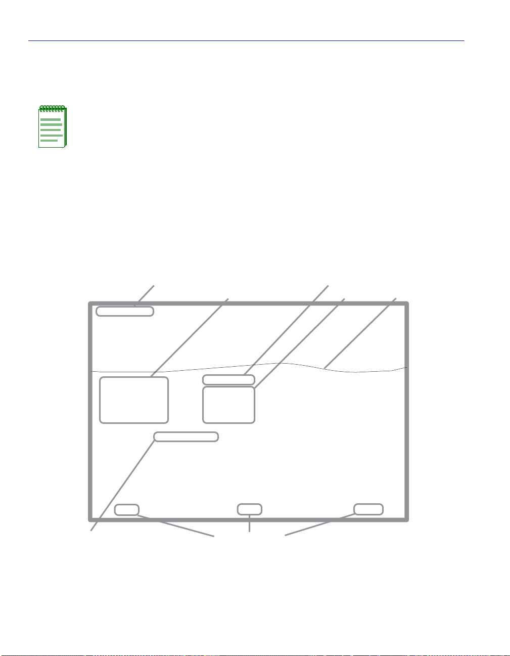
1.4 LOCAL MANAGEMENT SCREEN ELEMENTS
There are six types of screens used in Local Management: password, menu, statistics,
configuration, status, and warning screens. Each type of screen can consist of one to five basic
elements, or fields. Figure 1-1 shows an example of the fields in a screen. A description of each
field follows the figure.
Figure 1-1 Example of a Local Management Screen
Event Message Field
Event Message Line
Device Type: xxxxx-xx
MAC Address:
IP Address:
Subnet Mask:
Default Gateway:
TFTP Gateway IP Addr:
Operational Mode: [802.1Q SWITCHING]
Clear NVRAM [NO]
Selection Field
Display Fields
xxxxx-xx LOCAL MANAGEMENT
General Configuration
00-00-ID-00-00-00
0.0.0.0
255.255.0.0
NONE DEFINED
0.0.0.0
IP Fragmentation [ENABLED]
EXIT
Command Fields
Display Field
Input Fields
Firmware Revision: XX.XX.XX
BOOTPROM Revision: XX.XX.XX
Device Date:
Device Time:
Screen Refresh Time:
Screen Lockout Time:
Device Uptime XX D XX H XX M
10/11/97
14:23:00
30 sec.
15 min.
RETURNSAVE
See
Note
Note: This shows the location of the cut away that is used in most of the screen graphics
in this document. The top portion of the screen is cut away to eliminate repeating the same
information in each graphic.The screen title is contained in its figure title.
30691_01
1-4 Introduction
Page 29

Local Management Screen Elements
Event Message Field
This field briefly displays messages that indicate if a Local Management procedure was executed
correctly or incorrectly, that changes were saved or not saved to Non-Volatile Random Access
Memory (NVRAM), or that a user did not have access privileges to an application.
Table 1-1 describes the most common event messages. Event messages related to specific Local
Management applications are described with those applications throughout this manual.
Table 1-1 Event Messages
Message What it Means
SAVED OK One or more fields were modified, and saved to NVRAM.
NOT SAVED
--PRESS SAVE-TO KEEP CHANGES
NOTHING TO SAVE The SAVE command was executed, but nothing was saved to
Attempting to exit the LM screen after one or more fields were
modified, but not saved to NVRAM.
NVRAM because there were no configuration changes since the data
was last saved.
Display Fields
Display fields cannot be edited. These fields may display information that never changes, or
information that may change as a result of Local Management operations, user selections, or
network monitoring information. In the screens shown in this guide, the characters in the display
fields are in plain type (not bold). In the field description, the field is identified as being
“read-only”.
Input Fields
Input Fields require the entry of keyboard characters. IP addresses, subnet mask, default gateway
and device time are examples of input fields. In the screens shown in this guide, the characters in
the input fields are in bold type. In the field description, the field is identified as being
“modifiable”.
Selection Fields
Selection fields provide a series of possible values. Only applicable values appear in a selection
field. In the screens shown in this guide, the selections display within brackets and are in bold
type. In the field description, the field is identified as being either “selectab le” when there are mo re
than two possible values, or “toggle” when there are only two possible values.
Introduction 1-5
Page 30

Local Management Keyboard Conventions
Command Fields
Command fields (located at the bottom of Local Management screens) are used to exit Local
Management screens, save Local Management entries, or navigate to another display of the same
screen. In the screens shown in this guide, the characters in this field are all upper case and in bold
type. In the field description, the field is identified as being a “command” field.
1.5 LOCAL MANAGEMENT KEYBOARD CONVENTIONS
All key names appear as capital letters in this manual. Table 1-2 explains the keyboard
conventions and the key functions that are used.
Table 1-2 Keyboard Conventions
Key Function
ENTER Key
RETURN Key
Used to enter data or commands. These keys perform the same Local
Management function. For example, “Press ENTER” means that you
can press either ENTER or RETURN, unless this manual specifically
instructs you otherwise.
ESCAPE (ESC) Key Used to “escape” from a Local Management screen without saving
changes. For example, “Press ESC twice” means the ESC key must be
pressed quickly two times.
SPACE Bar
BACKSPACE Key
Used to cycle through selections in some Local Management fields.
Use the SPACE bar to cycle forward through selections and use the
BACKSPACE key to cycle backward through selections.
Arrow Keys (UP-ARROW, DOWN-ARROW, LEFT-ARROW, RIGHT-ARROW)
Used to move the screen cursor. For example, “Use the arrow keys”
means to press whichever arrow key moves the cursor to the desired
field on the Local Management screen.
DEL Key Used to remove characters from a Local Management field. For
example, “Press DEL” means to press the Delete key.
1-6 Introduction
Page 31

Getting Help
1.6 GETTING HELP
For additional support related to this device or document, contact Enterasys Netw orks using one of
the following methods:
World Wide Web http://www.enterasys.com/
Phone (603) 332-9400
Internet mail support@enterasys.com
FTP ftp://ftp.enterasys.com/
Login anonymous
Password your email address
To send comments or suggestions concerning this document, contact the Enterasys Networks
Technical Writing Department via the following email address: TechWriting@enterasys.com
Make sure to include the document Part Number in the email message.
Before calling the Enterasys Networks, have the following information ready:
• Your Enterasys Networks service contract number
• A description of the failure
• A description of any action(s) already taken to resolve the problem
(e.g., changing mode switches, rebooting the unit, etc.)
• The serial and revision numbers of all involved Enterasys Networks products in the network
• A description of your network environment (layout, cable type, etc.)
• Network load and frame size at the time of trouble (if known)
• The device history (i.e., have you returned the device before, is this a recurring problem, etc.)
• Any previous Return Material Authorization (RMA) numbers
Introduction 1-7
Page 32

Page 33

2
Local Management Requirements
This chapter provides information concerning the following:
• Management Terminal Setup (Section 2.1), which describes how to attach a Local Management
terminal to the Enterasys Networks host device.
• Telnet Connections (Section 2.2), which provides guidelines when using a T elnet connection to
access Local Management.
• Monitoring an Uninterruptible Power Supply (Section 2.3), which describes how to make a
connection from the COM port to an American Power Conv ersion (APC) Uninterruptible Power
Supply (UPS) device. This type of connection enables the SmartSwitch device to monitor the
power status in case of a power loss.
2.1 MANAGEMENT TERMINAL SETUP
Use one of the following systems to access Local Management:
• A PC or compatible device running a VT series emulation software package
• A Digital Equipment Corporation VT100 type terminal
• A VT type terminal running emulation programs for the Digital Equipment Corporation VT100
series
• A remote VT100 type terminal via a modem connection
• In-band via a Telnet connection
Local Management Requirements 2-1
Page 34

Management Terminal Setup
2.1.1 Console Cable Connection
Use the Console Cable Kit provided with the SmartSwitch device to attach the management
terminal to the SmartSwitch device COM port as shown in Figure 2-1.
To connect the SmartSwitch device to a PC or compatible device running the VT terminal
emulation, proceed as follows:
1. Connect the RJ45 connector at one end of the cable (supplied in th e kit) to the COM port on the
SmartSwitch device.
2. Plug the RJ45 connector at the other end of the cable into the RJ45-to-DB9 adapter (supplied in
the kit).
3. Connect the RJ45-to-DB9 adapter to the communications port on the PC.
NOTE: If using a modem between the VT compatible device and the COM port of the
SmartSwitch device, use the appropriate connector included in the console cable kit.
Refer to the modem manufacturer’s information for proper operation and setup of the
modem.
The 2H252-25R SmartSwitch device is shown in Figure 2-1 as an example.
Figure 2-1 Management Terminal Connection
FAST ETHERNET WORKGROUP SWITCH
2H252-25R
LED
MODE
RX-TX
DPX-SPD
PWR
RESET
CPU
COM
RJ45-to-DB9
PC
2-2 Local Management Requirements
2
4
1
3
2X 4X 6X 8X 10X 12X 14X 16X 18X 20X 22X 24X
56789
12
10
14
11
13
20
16
18
19
15
17
RJ45 COM Port
UTP Cable
with RJ45 Connectors
PC Adapter
22
24
21
23
30691_02
Page 35

2.1.2 Management Terminal Setup Parameters
Table 2-1 lists the setup parameters for the local management terminal.
Table 2-1 VT Terminal Setup
Display Setup Menu
Columns ->
Controls ->
Auto Wrap ->
Scroll ->
Text Cursor ->
Cursor Style ->
General Setup Menu
Mode ->
ID number ->
Cursor Keys ->
Power Supply ->
Communications Setup Menu
Transmit ->
Receive ->
XOFF ->
Bits ->
Parity ->
Stop Bit ->
Local Echo ->
Port ->
Transmit ->
Auto Answerback ->
Keyboard Setup Menu
Keys ->
Auto Repeat ->
Keyclick ->
Margin Bell ->
Warning Bell ->
80 Columns
Interpret Controls
No Auto Wrap
Jump Scroll
Cursor
Underline Cursor Style
VT100, 7 Bit Controls
VT100ID
Normal Cursor Keys
UPSS DEC Supplemental
2400, 4800, 9600, 19200
Receive=Transmit
XOFF at 64
8 bits
No Parity
1 Stop Bit
No Local Echo
DEC-423, Data Leads Only
Limited Transmit
No Auto Answerback
Typewriter Keys
any option
any option
Margin Bell
Warning Bell
Management Terminal Setup
Local Management Requirements 2-3
Page 36

Telnet Connections
2.2 TELNET CONNECTIONS
Once the SmartSwitch device has a valid IP address, the user can establish a Telnet session from
any TCP/IP based node on the network. Telnet connections to the SmartSwitch device require the
community name passwords assigned in the SNMP Community Names Configuration screen.
For information about setting the IP address, refer to Section 4.2.
For information about assigning community names, refer to Section 4.4.
Refer to the instructions included with the Te lnet application for information about establishing a
T elnet session.
If the SmartSwitch device is operating in the 802.1Q mode with configured VLANs, the
management station must be connected to a physical port on the device that is on the same VLAN
as the virtual Host Data Port. For more information about the virtual Host Data Port and the setup
information for remote management in a device that is to be configured with VLANs, refer to
Section 12.8.
2.3 MONITORING AN UNINTERRUPTIBLE POWER SUPPLY
If the SmartSwitch device is connected to an American Power Conversion (APC) Uninterruptible
Power Supply (UPS) device for protection against the loss of power, a connection from the
SmartSwitch device COM port to the UPS can be made to monitor the UPS power status. To use
the COM port for this purpose, it must be reconfigured to support the UPS connection using the
procedure described in Section 4.2.10. Refer to the UPS documentation for details on how to
access the status information.
The Console Cable Kit provided with the SmartSwitch device is used to connect the UPS to the
SmartSwitch device COM port as show n in Figure 2-2. To connect the UPS device to the COM
port, proceed as follows:
1. Connect the RJ45 connector at one end of the cable to the COM port on the SmartSwitch device.
2. Plug the RJ45 connector at the other end of the cable into the RJ45-to-DB9 male (UPS) adapter
(Enterasys Networks part number, 9372066).
3. Connect the RJ45-to-DB9 male (UPS) adapter to the female DB9 port on the rear of the UPS
device (refer to the particular UPS device’s user instructions for more specif ic information about
the monitoring connection).
2-4 Local Management Requirements
Page 37

Monitoring an Uninterruptible Power Supply
Figure 2-2 Uninterruptible Power Supply (UPS) Connection
UPS Device
DB9 Port
RJ45-to-DB9
UPS Adapter
FAST ETHERNET WORKGROUP SWITCH
2H252-25R
LED
MODE
RX-TX
DPX-SPD
RESET
COM
2
4
1
3
2X 4X 6X 8X 10X 12X 14X 16X 18X 20X 22X 24X
PWR
CPU
56789
12
10
16
14
18
11
13
15
17
RJ45 COM Port
UTP Cable
with RJ45 Connectors
22
20
24
21
19
23
30691_03
Local Management Requirements 2-5
Page 38

Page 39

3
Accessing Local Management
This chapter provides information about the following:
• Navigating through the Local Management screen hierarchy for 802.1Q Switching
(Section 3.1).
• Accessing the Password screen to enter a Local Management session (Section 3.2).
• Accessing the Device Menu screen and its menu items to gain access to the Local Management
screens including the security screens (Section 3.3).
• Accessing the Security Menu screen to control access to the switch’s host (Section 3.5).
• Accessing the Passwords (Section 3.6) and Radius Configuration (Section 3.7) screens. These
screens allow you to configure additional security by limiting access to Local Management
according to local access policy and remotely using the RADIUS Client feature.
• Accessing the Name Services Configuration screen (Section 3.8). This screen details additional
security components to permit password authentication via a Radius Server.
3.1 NAVIGATING LOCAL MANAGEMENT SCREENS
The switch Local Management application consists of a series of menu screens. Navigate through
Local Management by selecting items from the menu screens.
The hierarchy of the Local Management screens is shown in Figure 3-1.
NOTE: At the beginning of each chapter, a section entitled “Screen Navigation Path”
shows the path to the first screen described in the chapter.
Accessing Local Management 3-1
Page 40

Navigating Local Management Screens
Figure 3-1 802.1Q Switching Mode, LM Screen Hierarchy
Device Configuration Menu
General Configuration
Password
Device
Menu
SNMP Configuration Menu
System Resources Information
Flash Download Configuration
Port Configuration Menu
802.1 Configuration Menu
Spanning Tree Configuration Menu
Spanning Tree Configuration
Spanning Tree Port Configuration
PVST Port Configuration
802.1Q VLAN
Configuration Menu
802.1p
Configuration Menu
Port Priority
Configuration
Traffic Class
Information
Traffic Class
Configuration
Does not apply to MATRIX E7.
Transmit Queues
Configuration
Priority Classification
Configuration
Rate Limiting
Layer 3 Extensions Menu
Device Statistics Menu
Network Tools
Stat ic VLAN
Configuration
Current VLAN
Configuration
VLAN Port
Configuration
VLAN Classification
Configuration
Protocol Port
Configuration
IGMP/VLAN
Configuration
Switch Statistics
Interface Statistics
RMON Statistics
SNMP Community Names Configuration
SNMP Traps Configuration
Access Control List
Static VLAN Egress
Configuration
Current VLAN
Egress Configuration
Protocol Port
Configuration
Ethernet Interface
Configuration
Ethernet Port
Configuration
HSIM/VHSIM
Configuration
Redirect Configuration
Menu
Port Redirect
Configuration
VLAN Redirect
Configuration
* SmartTrunk
Configuration
or
Link Aggregation
Menu
802.3ad Port
802.3ad Port
Details
802.3ad Port
Statistics
802.3ad
Aggregator
802.3ad
Aggregator Details
802.3ad System
Broadcast
Suppression
Configuration
B
* Refer to the SmartTrunk User’s Guide for the screen hierarchy.
3-2 Accessing Local Management
Page 41

Navigating Local Management Screens
B
Security
Passwords
Radius Configuration
Name Services Configuration
System Authentication Configuration
EAP Configuration
EAP Statistics Menu
MAC Port Configuration
MAC Supplicant Configuration
EAP Session Statistics
EAP Authenticator Statistics
EAP Diagnostic Statistics
3.1.1 Selecting Local Management Menu Screen Items
Select items on a menu screen by performing the following steps:
1. Use the arrow keys to highlight a menu item.
2. Press ENTER. The selected menu item displays on the screen.
3.1.2 Exiting Local Management Screens
There are two ways to exit the Local Management (LM) screens.
Using the Exit Command
To exit LM using the EXIT screen command, proceed as follows:
1. Use the arrow keys to highlight the EXIT command at the bottom of the Local Management
screen.
2. Press ENTER. The Local Management Password screen displays and the session ends.
Using the RETURN Command
To exit LM using the RETURN command, proceed as follows:
1. Use the arrow keys to highlight the RETURN command at the bottom of the Local Management
screen.
2. Press ENTER. The previous screen in the Local Management hierarchy displays.
NOTE: The user can also exit Local Management screens by pressing ESC twice. This
exit method does not warn about unsaved changes and all unsaved changes are lost.
Accessing Local Management 3-3
Page 42

Password Screen
3. Exit from Local Management by repeating steps 1 and 2 until the Device Menu screen displays.
4. To end the LM session, use the arrow keys to highlight the RETURN command at the bottom
of the Device Menu screen.
5. Press ENTER. The Local Management Password screen displays and the session ends.
3.1.3 Using the NEXT and PREVIOUS Commands
If a particular Local Management screen has more than one screen to display its information, the
NEXT and PREVIOUS commands are used to navigate between its screens.
To go to the next or previous display of a screen, proceed as follows:
1. Highlight the applicable NEXT or PREVIOUS command at the bottom of the screen.
2. Press ENTER. The screen displays.
3.1.4 Using the CLEAR COUNTERS Command
The CLEAR COUNTERS command is used to temporarily reset all counters of a screen to zero to
allow you to observe counter activity over a period of time. To reset the counters, perform the
following steps:
1. Use the arrow keys to highlight the CLEAR COUNTERS command.
2. Press ENTER, the counters are reset to zero.
3.2 PASSWORD SCREEN
When to Use
To access the Device Menu screen to start a Local Management session via a Telnet connection or
local COM port connection. Whenever a connection is made to the switch, the Local Management
Password screen displays. Before continuing, you must enter a password, which is compared to the
previously stored passwords and associated management level access policy configured using the
Security screen described in Section 3.5.
The level of management access is dependent on the password and the associated Access Policy
configured in the Password Configuration screen described in Section 4.4.
3-4 Accessing Local Management
Page 43

Password Screen
NOTE: You can set the same string as a Security password and SNMP Community
Name. This will allow you to access and manage the switch whether you are starting
a
Local Management session via a Telnet connection or local COM port connection, or by
using a network SNMP management application.
If you use a string for the security password and a different one for the SNMP
Community Name, the tw o cannot be used interchangeably to access the switch. The
access levels can also be configured to be different.
How to Access
Turn on the terminal. Press ENTER (this may take up to four times, because the COM port of the
switch auto-senses the baud rate of the terminal) until the Local Management Password screen
displays. Figure 3-2 shows the Password screen.
Screen Example
Figure 3-2 Local Management Password Screen
xxxxxxxx LOCAL MANAGEMENT
Enterasys Networks, Inc.
P.O. Box 5005
Rochester, NH 03866-5005 USA
(603) 332-9400
c Copyright Enterasys Networks, Inc. 2001
Device Serial Number:
Device Hardware Revision:
Device Firmware Revision:
Device BOOTPROM Revision:
Enter Password:
xxxxxxxxxxxx
xxx
xx.xx.xx
xx.xx.xx
3650_10
Accessing Local Management 3-5
Page 44

Password Screen
Enter the Password and press ENTER. The default super-user access password is “public” or press
ENTER.
NOTE: If an invalid password is entered, the terminal beeps and the cursor returns to
the beginning of the password entry field.
Entering a valid passw ord causes the associated access level to display at the bottom of
the screen and the Device Menu screen to display.
If no activity occurs for a preset period of time , th e Local Manage ment Password screen
redisplays and the password has to be reentered.
3-6 Accessing Local Management
Page 45

Device Menu Screen
3.3 DEVICE MENU SCREEN
Screen Navigation Path
Password > Device Menu
When to Use
To access the Local Management screens of the switch.
How to Access
Enter a valid password in the Local Management Password screen as descri bed in Section 3.2, and
press ENTER. The Device Menu screen, Figure 3-3, displays.
Screen Example
Figure 3-3 Device Menu Screen
DEVICE CONFIGURATION MENU
DEVICE STATISTICS MENU
NETWORK TOOLS
SECURITY
EXIT
NOTE: If the terminal is idle for several minutes, the Local Management Password
screen redisplays and the session ends. This idle time can be changed in the General
Configuration screen described in Section 4.2.9.
Accessing Local Management 3-7
RETURN
35591_14
Page 46

Device Menu Screen
Menu Descriptions
Refer to Table 3-1 for a functional description of each menu item.
Table 3-1 Device Menu Screen Menu Item Descriptions
Menu Item Screen Function
DEVICE
CONFIGURATION
MENU
DEVICE
STATISTICS
MENU
Provides access to the Local Management screens that are used to
configure the switch and also provides access to the Port Configuration
Menu screen, 802.1 Configuration Menu screens, and the Layer 3
Extensions Menu screens.
The Port Configuration Menu screen pro vides access to the screens that
are used to set operating parameters specific to each port.
The 802.1 Configuration Menu screen provides access to the Spanning
Tree Configuration Menu screen, 802.1Q VLAN Configuration Menu
screen, and the 802.1p Configuration Menu screen. These screens are
used to set the basic switch operations, and provide access to screens to
configure VLANs, and assign port priorities.
For details about the screens, refer to:
Chapter 4 for the Device Configuration Menu screen,
Chapter 5 for the Port Configuration Menu screen,
Chapter 6 for the 802.1 Configuration Menu screen, and
Chapter 9 for the Layer 3 Extensions Menu screen.
Provides access to screens used to obtain statistics and performance
information for the switch. For details, refer to Chapter 10.
3-8 Accessing Local Management
Page 47

Table 3-1 Device Menu Screen Menu Item Descriptions (Continued)
Menu Item Screen Function
Device Menu Screen
NETWORK
TOOLS
SECURITY Provides access to the following screens:
The Network Tools function resides on the switch and consists of
commands that allow the user to access and manage network devices,
including the ability to Telnet to other devices. Chapter 11 explains
how to use the Network Tools utility.
• Module Login Passwords
• Radius Configuration
• Name Services Configuration
• System Authentication Configuration
• EAP Configuration
• EAP Statistics Menu
• MAC Port Configuration
• MAC Supplicant Configuration
Provides access to the Password screen. This screen allows the user to
set a login password for the device according to an access policy
(read-only , read-write, and super-user). A dif ferent passw ord can be set
for each access policy.
To prevent clearing the passwords, hardware switch 8 on the board of
the device can be disabled using this screen. For an overview of the
security available on this switch, refer to Section 3.4.
For more information about the Module Login Password screen, refer
to Section 3.6.
Accessing Local Management 3-9
Page 48

Device Menu Screen
Table 3-1 Device Menu Screen Menu Item Descriptions (Continued)
Menu Item Screen Function
SECURITY
(cont’d)
The Radius Configuration screen enables you to configure the Radius
client function on the switch to provide another restriction for access to
the Local Management screens. For more information on Radius
Client, refer to Section 3.4.
For more information about the Radius Configuration screen, refer to
Section 3.7.
The System Authentication Configuration, EAP Configuration, and
EAP Statistics Menu screens enable you to securely authenticate and
grant appropriate access to end user devices directly attached to the
switch ports. For more information about 802.1x port based network
access control, refer to Section 3.4.2.
For more information about the System Authentication Configuration,
EAP Configuration, and EAP Statistics Menu screens, refer to
Section 3.9, Section 3.10, and Section 3.11, respectively.
The MAC Port Configuration screen enables you to monitor the
authentication state of the supplicants associated with each port and
enable/disable, initialize, and force a revalidation of the port MAC
credential.
For more information about MAC port configuration, refer to
Section 3.12.
The MAC Supplicant Configuration screen enables you to see which
MAC authentication supplicants are active, their MAC address and
associated module ports, and enable you to initialize or reauthenticate
each of the supplicants.
For more information about the MA C Supplicant Configuration screen,
refer to Section 3.13.
3-10 Accessing Local Management
Page 49

Overview of Security Methods
3.4 OVERVIEW OF SECURITY METHODS
Six security methods are available to cont rol which users are allo wed access to the switch’ s host to
monitor and control the switch.
• Login Security Password – used to access the Device Menu screen to start a Local Management
session via a T elnet connection or local COM port connection. Whenever a connection is made
to the switch, the Local Management Password screen displays. Before continuing, you must
enter a login password, which is compared to the stored passwords and associated management
level access policies configured using the Security screen described in Section 3.5.
• SNMP Community String – allows access to the switch via a network SNMP management
application. To access the switch, you must enter an SNMP Community Name string. The level
of management access is dependent on the SNMP Community Name and the associated Access
Policy configured in the SNMP Community Names Configuration screen described in
Section 4.4.
NOTES: You can set the same string as a Security login password and SNMP
Community Name. This allows you to access and manage the switch whether you are
starting a Local Management session via a Telnet connection or local COM port
connection, or using a network SNMP management application.
If the login security password is different from the SNMP Community Name, the two
cannot be used interchangeably to access the switch.
• Host Access Control Authentication (HACA) – authenticates user access of T elnet management,
console local management and W ebVie w via a central Radius Client/Server application using the
Password screen described in Section 3.6. For an overview of HACA and a description of how
to set the to access policy using the Radius Configuration screen, refer to Section 3.4.1 and
Section 3.7.
• Host Access Control List (ACL) – allows only the defined list of IP Addresses to communicate
with the host for Telnet, WebView (HTTP) and SNMP. To set up these parameters refer to the
Host Access Control List (ACL) screen described in Section 4.6.
• 802.1X Port Based Network Access Control – provides a mechanism for administrators to
securely authenticate and grant appropriate access to end user devices (supplicants) directly
attached to switch ports. For more information, refer to Section 3.4.2.
• MAC Authentication – provides a mechanism for administrators to securely authenticate and
grant appropriate access to end user devices directly attached to switch ports. For more
information, refer to Section 3.4.3.
Accessing Local Management 3-11
Page 50

Overview of Security Methods
3.4.1 Host Access Control Authentication (HACA)
T o use HA CA, the embedded Radius Client on the switch must be configured to communicate with
the Radius Server, and the Radius Server must be configured with the password information. The
software used for this application provides the ability to centralize the Authentication,
Authorization, and Accounting (AAA) of the network resources. For more information, refer to the
RFC 2865 (Radius Authentication) and RFC 2866 (Radius Accounting) for a description of the
protocol.
Each switch has its own Radius Client. The client can be configured via the Radius Configuration
screen described in Section 3.7.
The IP address of the Radius Server and shared secret text string must be configured on the
Radius Client. The client uses the Password Authentication Protoc ol (PAP) to communicate the
user name and encrypted password to the Radius Server.
On the Radius Server, each user is configured with the following:
• name
• password
• access level
The access level can be set to one of the following levels for each user name:
• super-user
• read-write
• read-only
To support multiple access levels per user name, it involves sending back a different “FilterID”
attribute using some server feature to differentiate between the same user name with different
prefixes/suffixes. For example, “username@engineering” and “username@home” could each
return different access levels.
NOTE: This is a server-dependent feature.
3-12 Accessing Local Management
Page 51

Overview of Security Methods
Only one password is allowed per access level. This enables the Radius Server to track the users
accessing the switch host and how long they used the host application.
All radius values, except the server IPs and shared secrets, are assigned reasonable default values
when radius is installed on a new switch. The defaults are as follows:
• Client, disabled
• Timeout, 20 seconds
• Retries, 3
• Primary and secondary Authentication ports: 1812 (per RFC 2865)
• Primary and secondary Accounting ports: 1813 (per RFC 2866)
• Last-resort for local and remote is CHALLENGE
If only one server is configured, it must be the primary server. It is not necessary to reboot after the
client is reconfigured.
The client cannot be enabled unless the primary server is configured with at least the minimum
configuration information.
NOTE: The minimum additional information that must be configured to use a server is
its IP address and Shared Secret.
When the Radius Client is active on the switch, you are prompted by an authorization screen for a
user login name and password when attempting to access the host IP address via the local console
LM, Telnet to LM, or WebView application. The embedded Radius Client encrypts the
information entered by the user and sends it to the Radius Server for validation. Then the server
returns a yes or no response back to the client, allowing or denying the user to access the host
application with the proper access level.
An access-accept response returns a message USER AUTHORIZATION = <ACCESS LEVEL>
for 3 seconds and then the main screen of the application is displayed. An access-denied response
causes an audible “beep” and the screen to return to the user name prompt.
If the Radius Client is unable to receive a response from the Radius Server, because the Radius
Server is down or inaccessible, the Radius Client will time out to a default value of 20 seconds.
Accessing Local Management 3-13
Page 52

Overview of Security Methods
If the server returns an “access-accept” response (the user successfully authenticated), it must also
return a Radius “FilterID” attribute containing an ASCII string with the following fields in the
specified format:
“Enterasys:version=V:mgmt=M:policy=N”
Where:
V is the version number (currently V=1)
M is the access level for management, one of the following strings:
“su” for super-user access
“rw” for read-write access
“ro” for read-only access
N is the policy profile string (refer to the policy profile MIB)
NOTES:
1. Quotation marks (“ ”) ar e used for cla rification only, and a re not par t of the co mmand
strings.
2. If the FilterID attribute is not returned, or the “mgmt” field is absent or contains an
unrecognizable value, access to Local Management is denied.
3. Policy profiles are not yet deployed and the “policy=N” part may be omitte d.
The secondary server is always consulted if it is configured. Note that the minimum additional
information that must be configured to use a server is its IP and Shared Secret.
A backup secondary server is always consulted if it has been configured with its IP and Shared
Secret. If communication is lost to all servers, and the user is connected to the local console serial
port, the authorization screen will change to allow access to the switch by using the Local
Management Module password.
If the user is connected remotely via TELNET or WebView, the switch will continue to deny
access until communication with the Radius Server is operational again. Optionally, if the switch
has been configured to allow remote access, the switch can be configured to use the Local
Management Module password in the event of a Radius failure.
3-14 Accessing Local Management
Page 53

Overview of Security Methods
3.4.2 802.1X Por t Based Network Access Control
This section provides
• a brief description of 802.1X Port Based Network Access Control
,
• definitions of common terms and abbreviations, and
• an overview of the tasks that may be accomplished using the 802.1X and EAP security and
authentication features.
When using the physical access characteristics of IEEE 802 LAN infrastructures, the 802.1X
standard provides a mechanism for administrators to securely authenticate and grant appropriate
access to end user devices directly attached to switch ports. When configured in conjunction with
NetSight Policy Manager and Radius server(s), Enterasys Networks’ switchs can dynamically
administer user based policy that is specifically tailored to the end user’s needs.
3.4.2.1 Definitions of Terms and Abbreviations
Table 3-2 provides an explanatio n of authentication terms and abbre v iations used when describing
the 802.1X and EAP security and authentication features.
Table 3-2 Authentication Terms and Abbreviations
Term Definition
EAP Extensible Authentication Protocol (e.g., Microsoft IAS
Server and Funk Steel Belted Radius).
PAE Port Access Entity, device firmware that implements or
participates in the protocol.
PWA Port Web Authentication, an enterprise specific
authentication process using a web browser user-login
process to gain access to ports.
RADIUS Remote Authentication Dial In User Service.
Authenticator The entity that sits between a supplicant and the
authentication server. The authenticator’s job is to pass
authenticating information between the supplicant and
authentication server until an authentication decision is
made.
Accessing Local Management 3-15
Page 54

Overview of Security Methods
Table 3-2 Authentication Terms and Abbreviations (Continued)
Term Definition
Authentication Server Provides authentication service to an authenticator. This
service determines, by the credentials the supplicant
provides, whether a supplicant is authorized to access
services provided by the authenticator. The authentication
server can be co-located with an authenticator or can be
accessed remotely.
Supplicant The entity (user machine) that is trying to be authenticated
by an authenticator attached to the other end of that link.
3.4.2.2 802.1X Security Overview
The Enterasys Networks’ SmartSwitch 2200 Series modules support the following 802.1X and
EAP security and authentication features to:
• Authenticate hosts that are connected to dedicated switch ports.
• Authenticate based on single-user hosts. (If a host is a time-shared Unix or VMS system,
successful authentication by any user will allow all users access to the network.)
• Allow users to authenticate themselves by logging in with user names and passwords, token
cards, or other high-level identification. Thus, a system manager does not need to spend hours
setting low-level MAC address filters on every edge switch to simulate user-level access
controls.
• Divide system functionality between supplicants (user machines), authenticators, and
authentication servers. Authenticators reside in edge switches. They shuffle message s and tell
the switch when to grant or deny access, but do not validate logins. User v alidation is the job of
authentication servers. This separation of functions allows network managers to put
authentication servers on central servers.
• Use the 80 2.1X protocol to communicate between the authenticator and the supplicant. the
frame format using 802.1X incl;udes extra data fields within a LAN frame. Note that 802.1X
does not allowrouting.
• Use the 80 2.1X protocol to communicate between the authenticator and the authentication
server. The specific protocol that runs between these comp on en ts (e.g., RADIUS-e nc a psulated
EAP) is not specified and is implementation-dependent.
3-16 Accessing Local Management
Page 55

Overview of Security Methods
3.4.3 MAC Authentication Overview
This section discusses a method for a user to gain access to the network by validating the MAC
address of their connected device. Network management statically provisions MAC addresses in a
central radius server. Those pre-configured MAC addresses are allowed access to the network
through the usual RADIUS validation process. This section further discusses how MAC
Authentication and 802.1X cooperate to provide an integrated approach to authentication.
3.4.3.1 Authentication Method Selection
The 802.1X and PWA authentication methods are globally exclusive. Additionally, MAC
Authentication and PWA are globally mutually exclusive. However, MAC Authentication and
802.1X are not mutually exclusive, so that both 802.1X and MAC authentications can be
configured concurrently on the same device using the Local Management (LM) System
Authentication Configuration screen described in Section 3.9. When both methods are enabled on
the same device, the switch enforces a precedence relationship between MAC Authentication and
802.1X methods.
When configuring a device using the System Authentication Configuration screen, only the valid
set of global and per port authentication methods are available for selection. These are EAP, PWA,
MAC, MA C EAP, and NONE. If there is an attempt to enable both MAC Authentication and PWA
either through the sole use of MIBs or by using both the LM screen and MIBs, then an appropriate
error message is displayed.
3.4.3.2 Authentication Method Sequence
When MAC Authentication is enabled on a port, the Authentication of a specific MAC address
commences immediately following the reception of any frame. The MAC address and a currently
stored password for the port are used to perform a PAP authentication with one of the configured
radius servers. If successful, the port forwarding behavior is changed according to the authorized
policy and a session is started. If unsuccessful, the forwarding behavior of the port remains
unchanged.
If successful, the filter-id in the radius response may contain a policy string of the form
policy=”policy name”. If the string exists and it refers to a currently configured policy in this
switch, then the port receives this new policy. If authenticated, but the authorized policy is invalid
or non-existent, then the port forwards the frame normally according to the port default policy, if
one exists. Otherwise, frames are forwarded without any policy.
3.4.3.3 Concurrent Operation of 802.1X and MAC
Accessing Local Management 3-17
Page 56

Overview of Security Methods
Authentication
This section defines the precedence rules to determine which authentication method, 802.1X
(EAP) or MAC Authentication has control over an interface. Setting the 802.1X and MAC port
authentication is described in Section 3.9.
When both methods are enabled, 802.1X takes precedence over MAC Authentication when a user
is authenticated using the 802.1X method. If the port or MA C remains unauthenticated in 80 2.1X,
then MAC authentication is active and may authenticate the next MAC address received on that
port.
It is also recommended to have a state whereby 802.1X is completely disabled on a port leaving
MAC-Authentication active. 802.1X does not explicitly provide any per port enable or disable of
its authentication mechanism.
You can configure MAC Authentication and 802.1X to run concurrently on the same module, but
exclusively on distinct interfaces of that module. To achieve this, the 802.1X port behavior in the
force-unauthorized state is overloaded. When 802.1X and MAC Authentication are enabled,
setting the 802.1X MIB to force-unauthorized for the interface in question and enabling
MAC Authentication. This allows the MAC Authentication to run unhindered by 802.1X on that
interface. This, in effect, disables all 802.1X control over that interface. However, if a default
policy exists on that port, the switch forwards the frames according to that policy, otherwise the
switch drops them.
If a switch port is configured to enable both 802.1X and MAC Authentication, then it is possible
for the switch to receive a start or a response 802.1X frame while a MAC Authentication is in
progress. If this situation, the switch immediately aborts MAC Authentication. The 802.1X
authentication then proceeds to completion. After the 802.1X login completes, the user has either
succeeded and gained entry to the network, or failed and is denied access to the network.
Regardless of success, after the 802.1X login attempt, no new MAC Authentication logins occur
on this port until:
• A link is toggled.
• The user executes an 802.1X logout.
• Management terminates the 802.1X session.
NOTE: The switch may terminate a session in many different ways. All of these
reactivate the MAC authentication method. Refer to Table 3-3 for the precedence
relationship between MAC and 802.1X authentication.
When a port is set for concurrent use of MAC and 802.1X authentication, the switch continues to
issue EAPOL request/id frames until a MAC Authentication succeeds or the switch receives an
EAPOL response/id frame.
3-18 Accessing Local Management
Page 57

Table 3-3 MAC / 802.1X Precedence States
802.1X
Port
Control
MAC
Port
Control
Authenticated?
Default
Policy
Exists?
Authorized
Policy
Exists?
Overview of Security Methods
Action
Force
Authorized
Force
Authorized
Auto Enabled Yes Don’t
Don’t
Care
Don’t
Care
Don’t
Care
Don’t
Care
Yes Don’t
Care
No Don’t
Care
Yes
Care
Auto Enabled Yes Yes No
Auto Enabled Yes No No
• Neither method performs
authentication.
• Frames are forwarded according
to default policy.
• Neither method performs
authentication.
• Frames are forwarded.
• Hybrid authentication (both
methods are active).
• Frames are forwarded according
to authorized policy.
• Hybrid authentication (both
methods are active).
• Frames are forwarded according
to default policy.
• Hybrid authentication (both
methods active).
• Frames are forwarded.
Auto Enabled No Yes Don’t
• Hybrid authentication (both
Care
• Frames are forwarded according
Auto Enabled No No Don’t
Care
• Hybrid authentication (both
• Frames are discarded.
Accessing Local Management 3-19
methods are active).
to default policy.
methods are active).
Page 58

Overview of Security Methods
Table 3-3 MAC / 802.1X Precedence States (Continued)
Autho-
802.1X
Port
Control
MAC
Port
Control
Authenticated?
Default
Policy
Exists?
rized
Policy
Exists?
Action
Auto Disabled Yes Don’t
Care
Auto Disabled Yes Yes No
Yes • 802.1X performs authentication.
• Frames are forwarded according
• 802.1X performs authentication.
• Frames are forwarded according
Auto Disabled Yes No No
• 802.1X performs authentication.
• Frames are forwarded.
Auto Disabled No Yes Don’t
Care
Auto Disabled No No Don’t
Care
Force
Unauthoriz
Enabled Yes Don’t
Care
Yes
ation
• 802.1X performs authentication.
• Frames are forwarded according
• 802.1X performs authentication.
• Frames are discarded.
• MAC performs authentication.
• Frames are forwarded according
to authorized policy.
to default policy.
to default policy.
to authorized policy.
Force
Enabled Yes Yes No
Unauthoriz
ation
Force
Enabled Yes No No
Unauthoriz
ation
Force
Enabled No Yes Don’t
Unauthoriz
ation
3-20 Accessing Local Management
Care
• MAC performs authentication.
• Frames are forwarded according
to default policy.
• MAC performs authentication.
• Frames are forwarded.
• MAC performs authentication.
• Frames are forwarded according
to default policy.
Page 59

Table 3-3 MAC / 802.1X Precedence States (Continued)
Autho-
802.1X
Port
Control
MAC
Port
Control
Authenticated?
Default
Policy
Exists?
rized
Policy
Exists?
Overview of Security Methods
Action
Force
Unauthoriz
ation
Force
Unauthoriz
ation
Enabled No No Don’t
Care
Disabled Don’t
Care
Don’t
Care
Don’t
Care
• MAC performs authentication.
• Frames are discarded.
• Neither method performs
authentication.
• Frames are discarded.
3.4.4 MAC Authentication Control
This global variable can be set to enabled or disabled.
If set to enabled, then
a. MAC Authentication is active on those ports whose indi vidual port-enabled variable is set to
enabled.
b. All session and statistic information is reset to defaults.
c. Any MAC addre sses currently locked to ports are unlocked.
If set to disabled, then
a. MAC Authentication stops for all ports.
b. All active sessions are terminated with the cause portAdminDisabled.
c. All policies are applied to ports as a result of a MAC Authentication reverting to the ports
default policy, if any.
d. All ports currently authenticated using 802.1X, are unaffected.
e. Any 802.1X ports, which were set to forced-unauth, revert back to discarding all frames
regardless of the MAC Authentication state.
Accessing Local Management 3-21
Page 60

Security Menu Screen
3.5 SECURITY MENU SCREEN
Screen Navigation Path
Password > Device Menu > Security
When to Use
To access the Passwords, Radius Configuration, Name Services Configuration, System
Authentication Configuration, EAP Configuration, EAP Statistics Menu, MAC Port
Configuration, and MAC Supplicant Configuration screens.
• The Passwords and Radius Configuration screens allow you to configure additional limited
access.
• The Name Services Configuration screen allows you to set parameters for personalized web
authentication.
• The System Authentication Configuration, EAP Configuration, EAP Statistics Menu screens
enable you to view port authentication type and status, to configure EAP settings, and to view
EAP statistics.
• The MAC Port Configuration and MAC Supplicant Configuration screens enable you to
configure MAC Authentication for user devices (supplicants) directly attached to one or more
physical ports.
How to Access
Use the arrow keys to highlight the SECURITY menu item on the Device Configuration Menu
screen and press ENTER. The Security Menu screen, Figure 3-4, displays.
3-22 Accessing Local Management
Page 61

Screen Example
Figure 3-4 Security Menu Screen
PASSWORDS
RADIUS CONFIGURATION
NAME SERVICES CONFIGURATION
SYSTEM AUTHENTICATION CONFIGURATION
EAP CONFIGURATION
EAP STATISTICS MENU
MAC PORT CONFIGURATION
MAC SUPPLICANT CONFIGURATION
Security Menu Screen
EXIT
Menu Descriptions
Refer to Table 3-4 for a functional description of each menu item.
RETURN
3528_14
Accessing Local Management 3-23
Page 62

Security Menu Screen
Table 3-4 Security Menu Screen Menu Item Descriptions
Menu Item Screen Function
PASSWORDS Used to set the Locally Administered Passwords (super user,
read-write, and read-only) to access the device according to an access
policy. For details, refer to Section 3.6.
RADIUS
CONFIGURATION
NAME SERVICES
CONFIGURATION
SYSTEM
AUTHENTICATION
CONFIGURATION
EAP
CONFIGURATION
EAP STATISTICS
MENU
MAC PORT
CONFIGURATION
MAC SUPPLICANT
CONFIGURATION
Used to configure the Radius Client Parameters on the switch,
primary server, and secondary server. For details, refer to Section 3.7.
Used to set parameters for personalized Web authentication, including
the URL and IP of the Secure Harbour web page. For details, refer to
Section 3.8.
Used to enable or disable an authentication type for the device, and to
display the authentication type and authentication status (enabled or
disabled) for all ports. For details, refer to Section 3.9.
Used to configure authentication settings for each port. For details,
refer to Section 3.10.
Used to navigate to the EAP Session Statistics, EAP Authentication
Statistics, and EAP Diagnostic Statistics screens. For details, refer to
Section 3.11.
Used to view the current port authentication states, enable or disable
the authentication function on each port, reset ports to the initial
authentication configuration, and force a revalidation of the MAC
credential. For details, refer to Section 3.12.
Used to show how long MAC Authentication supplicants are logged
on to a port and their MAC address, and provides limited
configuration of these supplicants. For details, refer to Section 3.13.
3-24 Accessing Local Management
Page 63

Passwords Screen
3.6 PASSWORDS SCREEN
When to Use
T o pro vide additional security b y using login passwords associated to an access policy. This screen
allows the use of passwords to provide three levels of Local Management access (super-user,
read-write and read-only) via serial console or telnet connection. This screen is also used to disable
the function of hardware switch 8 to prevent the clearing of the login passwords.
How to Access
Use the arrow keys to highlight the PASSWORDS menu item on the Security Menu screen and
press ENTER. The Module Login Passwords screen, Figure 3-5, displays.
Screen Example
Figure 3-5 Module Login Passwords Screen
Password Access Policy
******** read-only
******** read-write
******** super-user
SWITCH 8 [ENABLED]
Restrict NVRAM Passwords from upload/download [DISABLED]
EXIT RETURNSAVE
Accessing Local Management 3-25
3650_23
Page 64

Passwords Screen
Field Descriptions
Refer to Table 3-5 for a functional description of each screen field.
Table 3-5 Module Login Passwor ds Screen Field Descriptions
Use this field… To…
Password
(Modifiable)
Access Policy
(Read-only)
SWITCH 8
(Toggle)
Restrict NVRAM
Passwords from
Upload/Download
(Toggle)
Enter the password used to access the device according to an access
policy.
See the access given each password. Possible selections are as follows:
read-only This password allows read-only access to the Local
Management, and excludes access to
security-protected fields of read-write or super-user
authorization.
read-write This password allows read and write access to Local
Management, excluding security protected fields for
super-user access only.
super-user This password permits read-write access to Local
Management and allows the user to change all
modifiable parameters including community names, IP
addresses, traps, and SNMP objects.
Enable or disable the function of hardware switch S8 on the main
board of the device. When set to ENABLED, S8 can be used to clear
the password. When set to DISABLED, S8 cannot be used to clear the
password. The default is Enable.
Prevent passwords residing in NVRAM from being replaced when
downloading a configuration file. The default setting is DISABLED.
This prevents the passwords from being downloaded.
3-26 Accessing Local Management
Page 65

Radius Configuration Screen
3.6.1 Setting the Module Login Password
Setting the Module Login Password provides additional security by assigning each switch its own
password and allows you to disable the function of switch S8 so that the password cannot be
cleared.
To assign the password and disable switch S8, proceed as follows:
1. Use the arrow keys to highlight the appropriate Password field. A different password can be
assigned to each Access Policy.
2. Press ENTER.
3. To disable the function of switch S8 so the passwords cannot be cleared, use the arrow keys to
highlight the Switch 8 field.
4. Press the SPACE bar to select DISABLED.
5. To save the settings, press ENTER. The message “SAVED OK” displays at the top of the screen.
3.7 RADIUS CONFIGURATION SCREEN
When to Use
To configure the Radius client in the switch to restrict access to the management functions of the
Local Management screens, by way of the COM port or network TELNET connection.
NOTE: The configuration and Enable State of the Radius client will be stored in
NVRAM and loaded on power-up. If the client is properly configured and enabled, the
platform will create the Radius client and enable it at boot time, superseding legacy
authentication. Otherwise, the legacy authentication becomes operational.
Radius Client parameters can also be set using th e Network Tools screen described in
Chapter 11.
This screen allows you to set the necessary parameters to centralize the Authentication,
Authorization, and Accounting of the network resources. For information about Rad ius Client an d
how it functions, refer to Section 3.4 and Section 3.4.1.
Accessing Local Management 3-27
Page 66

Radius Configuration Screen
How to Access
Use the arrow keys to highlight the RADIUS CONFIGURATION menu item on the Security
Menu screen and press ENTER. The Radius Configuration screen, Figure 3-6, displays.
Screen Example
Figure 3-6 Radius Configuration Screen
Timeout: 20
Retries: 03
Local Remote
Last Resort Action: [CHALLENGE] [CHALLENGE]
Radius Client: [DISABLED]
IP Address: Secret: Auth Port:
0.0.0.0 NOT CONFIGURED 1812
0.0.0.0 NOT CONFIGURED 1812
SAVE
EXIT RETURN
Field Descriptions
Refer to Table 3-6 for a functional description of each screen field.
Table 3-6 Radius Configuration Screen Field Descriptions
Use this field… To…
Timeout
(Modifiable)
Retries
(Modifiable)
3-28 Accessing Local Management
Enter the maximum time in seconds to establish contact with the
Radius Server before timing out. The default is 20 seconds.
Enter the maximum number of attempts (1…N) to contact the Radius
Server before timing out. The default is 20 seconds.
3650_22
Page 67

Radius Configuration Screen
Table 3-6 Radius Configuration Screen Field Descriptions (Continued)
Use this field… To…
Last Resort
Action/Local
(Selectable)
Last Resort
Action/Remote
(Toggle)
Radius Client
(Toggle)
Accept, Challenge, and Reject, which do the following:
ACCEPT: Allows local access (via COM port) at the super-user
level with no further attempt at authentication.
CHALLENGE: Reverts to local module (legacy) passwords.
REJECT: Does not allow local access.
For more details, refer to Section 3.7.1.
To set local and remote servers, refer to Section 3.7.2.
Accept, Challenge, and Reject, which do the following:
ACCEPT: Allows remote access (via Telnet or WebView) at the
super-user level with no further attempt at authentication.
CHALLENGE: Reverts to local module (legacy) passwords.
REJECT: Does not allow remote access.
For more details, refer to Section 3.7.1.
To set local and remote servers, refer to Section 3.7.2.
Enable or disable client status.
IP Address
(Modifiable)
Secret
(Modifiable)
Auth Port
(Modifiable)
Enter the IP address (in decimal-dot format) of the primary and
secondary servers being configured for the RADIUS function.
Enter a secret string of characters or the primary and secondary server
(16 characters are recommended as per RFC 2865). The maximum is
32 characters).
Enter the number of the Authorization UDP Port for the Primary and
Secondary server.
Accessing Local Management 3-29
Page 68

Radius Configuration Screen
3.7.1 Setting the Last Resort Authentication
The Radius client can be configured to use primary and secondary servers. If the primary server
does not respond within the specified number of retries during the specified time-out period, the
client will then attempt to authenticate using the secondary server. If the secondary server also
does not respond, then the client returns a time-out condition.
The “last resort” platform action in case of Radius server time-out for both local and remote access
is selectable for each type of access:
• Local login via the COM port.
• Remote login via a remote network TELNET connection.
3.7.2 Setting the Local and Remote Servers
Before setting the parameters, refer to Section 3.4.1 and Section 3.7.1 for a better understanding of
Radius Servers and Last Resort Authentication. To set the local and remote server, proceed as
follows:
1. Highlight the Timeout field and enter the maximum time in seconds to establish contact with
the Radius Server before timing out.
2. Highlight the Retries field and enter the desired maximum number of attempts (1…N) to contact
the Radius Server before timing out.
3. Highlight the Last-Resort Action/Local field and select ACCEPT, CHALLENGE, or
REJECT to allow local access at the super-user level with no further attempt at authentication;
revert local module to (legacy) passwords, or not allow local access.
4. Highlight the Last-Resort Action/Remote field select ACCEPT, CHALLENGE, or
REJECT to allow remote access at the super-user level with no further attempt at
authentication, revert remote module to (legacy) passwords, or not allow remote access,
respectively.
5. Use the arrow keys to highlight the IP Address field and enter the IP address (in decimal-dot
format) of the primary and secondary servers being configured for the RADIUS function.
6. Highlight the Secret field and enter a secret string of characters or the primary and secondary
server (16 characters are recommended as per RFC 2865. The maximum is 32 characters).
7. Highlight the Auth Port field and enter the number of the Accounting UDP Port for the Primary
and Secondary server.
8. Use the arrow keys to highlight the SAVE command and press ENTER to save your settings.
3-30 Accessing Local Management
Page 69

Name Services Configuration Screen
3.8 NAME SERVICES CONFIGURATION SCREEN
When to Use
Use this screen when enabling Port-based Web authentication. This screen can also be used to
configure the global Secure Harbour name and IP address. The user can Enable/Disable Name
Services and associate the switch name with the Secure Harbour IP address.
How to Access
Use the arrow keys to highlight the NAME SERVICES CONFIGURATION menu item on the
Security Menu screen and press ENTER. The Name Services Configuration screen, Figure 3-7,
displays.
Screen Example
Figure 3-7 Name Services Configuration Screen
Secure Harbour IP:
Name Services:
Web Authentication:
SAVE
Switch Name:
EXIT
Secure Harbour
0.0.0.0
[DISABLED]
[DISABLED]
RETURN
3650_21
Accessing Local Management 3-31
Page 70

Name Services Configuration Screen
Field Descriptions
Refer to Table 3-7 for a functional description of each screen field.
Table 3-7 Name Services Configuration Screen Field Descriptions
Use this field… To…
Switch Name
(Modifiable)
Secure Harbour IP
(Read-Only)
Name Services
(Toggle)
Web Authentication
(Toggle)
Create a textual name to bind to the IP address.
NOTE: The switch Name and the Secure Harbour IP must be
globally unique within your network and the end switch must
contain the identical information.
See the IP address used to access services.
NOTE: T he Switch Nam e an d th e Sec ur e Harb ou r IP must be
globally unique within your network and the end switch must
contain the identical information. The Secure Harbour IP can not
be the same as the management IP of the switch.
Enable or disable the name services function.
Enable or disable Web Authentication.
3-32 Accessing Local Management
Page 71

System Authentication Configuration Screen
3.9 SYSTEM AUTHENTICATION CONFIGURATION SCREEN
When to Use
To enable or disable an authentication type for the device, and to display the authentication type
and authentication status (enabled or disabled) for all ports.
How to Access
Use the arrow keys to highlight the SYSTEM AUTHENTICATION CONFIGURATION menu
item on the Security Menu screen and press ENTER. The System Authentication Configuration
screen, Figure 3-8, displays.
Screen Example
Figure 3-8 System Authentication Configuration Screen
System Authentication [EAP]
Port # Authentication Type Authentication Status
1 EAP Unauthenticated
2 EAP Unauthenticated
3 EAP-MAC Unauthenticated
4 EAP Unauthenticated
5 EAP Unauthenticated
6 EAP Unauthenticated
7 EAP-MAC Unauthenticated
8 EAP-MAC Unauthenticated
9 EAP Unauthenticated
10 EAP Unauthenticated
EXITNEXTSAVE
RETURN
Accessing Local Management 3-33
37831-02
Page 72

System Authentication Configuration Screen
Field Descriptions
Refer to Table 3-8 for a functional description of each screen field.
Table 3-8 System Authentication Configuration Screen Field Descriptions
Use this field… To…
System
Authentication
(Selectable)
Port #
(Read-Only)
Enable or disable an authentication type for the device, or turn off the
port authentication function on all ports. Options are EAP (Extensible
Authentication Protocol), PWA (Port Web Authentication), MAC
(Machine Address Code), EAP MAC, or NONE.
• EAP is encapsulated in LAN frames according to the 802.1X
standard.
• PWA uses the web browser user login process to allow access to
ports.
• MAC authentication limits access to the network by validating the
MAC address of their connected devices.
• EAP MAC enables using both MAC and EAP authentication
methods concurrently for security.
• NONE turns off all port authentication in the switch. The default is
NONE.
To select the option, use the arrow keys to highlight the System
Authentication field, step to EAP, PWA, MAC, EAP MAC, or
NONE using the SPACE bar, then press ENTER.
See the port numbers of all ports known to the device. Up to 10 ports
can be displayed at a time. To see additional ports, select NEXT and
press ENTER to display the authentication type and status for the next
10 ports.
Authentication Type
(Read-Only)
Authentication
Status
(Read-Only)
3-34 Accessing Local Management
See the authentication type configured for each port: EAP, PWA,
MAC, EAP MAC, or NONE.
See whether the port is authenticated for the chosen authentication
type. Status is Authenticated, EAP Authenticated, MAC
Authenticated, or Unauthenticated.
Page 73

EAP (Port) Configuration Screen
3.10 EAP (PORT) CONFIGURATION SCREEN
When to Use
To configure authentication settings for each port.
How to Access
Use the arrow keys to highlight the EAP CONFIGURATION menu item on the Security Menu
screen and press ENTER. The EAP Port Configuration screen, Figure 3-9, displays.
Screen Example
Figure 3-9 EAP Port Configuration Screen
Port Authentication
State
--------------------------------------------------------------------------------------------------- 1 initialize idle [Auto] [FALSE] [FALSE] [2]
2 initialize idle [Auto] [FALSE] [FALSE] [2]
3 initialize idle [Auto] [FALSE] [FALSE] [2]
4 initialize idle [Auto] [FALSE] [FALSE] [2]
5 initialize idle [Auto] [FALSE] [FALSE] [2]
6 initialize idle [Auto] [FALSE] [FALSE] [2]
7 initialize idle [Auto] [FALSE] [FALSE] [2]
8 initialize idle [Auto] [FALSE] [FALSE] [2]
9 initialize idle [Auto] [FALSE] [FALSE] [2]
10 initialize idle [Auto] [FALSE] [FALSE] [2]
Backend
State
Por t
Control
Initialize
Por t
Force
Reauth
RETURNEXITNEXTSAVE
Maximum
Requests
37831_03
Accessing Local Management 3-35
Page 74

EAP (Port) Configuration Screen
Field Descriptions
Refer to Table 3-9 for a functional description of each screen field.
.
Table 3-9 EAP Port Configuration Screen Field Descriptions
Use this field… To…
Port
(Read-Only)
Authentication State
(Read-Only)
See the port number of all ports known to the device. Up to 10 ports
can be displayed as a time. Highlight NEXT and press ENTER to
display the next set of ports.
See the current authentication state of each port.
These following nine described states are the possible internal states
for the authenticator. Some states are simply pass-through states
causing a small action and immediately moving to a new state.
Therefore, not all states can be observed for this interface.
• initialize: A port is in the initialize state when:
a. EAP authentication is disabled,
b. EAP authentication is enabled and the port is not linked, or
c. EAP authentication is enabled and the port is linked. (In this case
very little time is spent in this state, it immediately transitions to
the connecting state, via disconnected.
• disconnected: The port passes through this state on its way to
connected whenever the port is reinitialized, via link state change,
reauthentication failure, or management intervention.
• connecting: While in this state, the authenticator sends request/ID
messages to the supplicant.
• authenticating: The port enters this state from connecting after
receiving a response/ID from the supplicant. It remains in this state
until the entire authentication exchange between the supplicant and
the authentication server completes.
• authenticated: The port enters this state from authenticating state
after the exchange completes with a favorable result. It remains in
this state until linkdown, logoff, or until a reauthentication begins.
3-36 Accessing Local Management
Page 75

EAP (Port) Configuration Screen
Table 3-9 EAP Port Configuration Screen Field Descriptions (Continued)
Use this field… To…
Authentication State
(Cont’d)
Backend State
(Read-Only)
• aborting: The port enters this state from authenticating when any
event occurs that interrupts the login exchange.
• held: After any login failure, this state is entered where the port
remains for the number of seconds equal to quietPeriod (can be set
using mib).
• forceAuth: Management has set this in “Port Control”. This allows
normal, unsecured switching on this port.
• forceUnauth: Management has set this in “Port Control”.
Absolutely no frames are forwarded to or from this port.
See the current backend state of each port.
The backend state machine controls the protocol interaction between
the authenticator (the switch) and the authentication server (typically
a radius server).
These following seven states are the possible internal states for the
authenticator. Some states are simply pass-through states causing a
small action and immediately moving to a new state. Therefore, you
may not observe all of the states in this interface.
For more detail, please see the IEEE Standard 802.1X-20001, Port
Based Network Access Control.
• request: The port has received a request from the server and is
waiting for a response from the supplicant.
• response: The port has received a response from the server and is
waiting for either another request or an accept or reject from the
server.
• success: The port has received a success from the server. Send a
success to the supplicant and move to idle.
• fail: The port has received a reject from the server. Send a fail to the
supplicant and move to idle.
• timeout: The port has timed-out during the authentication exchange.
Accessing Local Management 3-37
Page 76

EAP (Port) Configuration Screen
Table 3-9 EAP Port Configuration Screen Field Descriptions (Continued)
Use this field… To…
Backend State
(Cont’d)
Port Control
(Selectable)
• idle: The port is currently not involved in any authentication, but is
ready to begin one. Move to idle after completion.
• initialize: The port is initializing the rele v ant backend v ariables and
is not ready to begin an authentication. Move to idle after
completion.
Set the port control mode enabling network access for each port.
Modes include:
• Auto: In this mode, frames are forwarded according to the
authentication state of each port. When no default policy has been
applied to the port, and its authentication state is unauthorized, the
port discards all incoming and outgoing frames. If a default policy is
applied to the port and its authentication state is unauthorized,
frames are forwarded according to the configuration specified for
that policy.
Once authorized, a port forwards frames according to its current
configuration. A policy string may be returned by the Radius Server
in the filter id attribute. This policy string can reference a set of
VLAN and priority classification rules pre-configured in the switch.
If a policy string is returned as part of the user authorization process,
then frames are forwarded according to the configuration specified
by that policy.
If no policy is returned, the switch forwards frames using the
existing default policy configuration, if it exists, or the current
configuration for the port if no default policy exists. If the default
policy is used, then we interpret that default policy to now be active
on the controlled port. Although continuing to use the default policy
after authorization may be a legal configuration, there are no
practical uses.
If a policy string is returned that has no definition in the switch, then
this is an illegal configuration and the port is not authenticated.
Therefore frame forwarding in this case follows the rules outlined
above for an unauthorized port.
3-38 Accessing Local Management
Page 77

EAP (Port) Configuration Screen
Table 3-9 EAP Port Configuration Screen Field Descriptions (Continued)
Use this field… To…
Port Control
(Cont’d)
Initialize Port
(Single Setting)
Force Reauth
(Single Setting)
• Forced Authenticated Mode: The Forced Authenticated Mode is
meant to disable authentication on a port. It is intended for ports that
support ISLs and devices that cannot authenticate, such as printers
and file servers. If a default polic y is applied to the port via the Policy
Profile MIB, then frames are forwarded according to the
configuration set by that policy, otherwise frames are forwarded
according to the current configuration for that port. Authentication
using 802.1X is not possible on a port in this mode.
• Forced Unauthenticated Mode: When a port is set to the Forced
Unauthenticated Mode, all frames received on the port are discarded
by a filter. Authentication using 802.1X is not possible on a port in
this mode.
Set to TRUE to initialize all state machines for this port. After
initialization, authentication can proceed normally on this port
according to its control settings. This has the effect of kicking off any
currently authorized user on the port and resetting the session
information for a new login.
You can only set this field to TRUE to initialize the port. Afterwards
the field immediately reverts to FALSE.
Set to TRUE to cause an immediate forced reauthentication for a user
who is currently logged on to the port. If the reauthentication fails, then
the user is forced off the port. If there is no user on the port, a setting of
TRUE of this v ariabl e has no ef fect. Setting this v ariable to FALSE has
no effect.
Maximum Requests
(Modifiable)
Set the maximum number of times EAP request frames will be
transmitted to the supplicant before timeout. Default is 2; range is 1
to 10.
Accessing Local Management 3-39
Page 78

EAP Statistics Menu Screen
3.11 EAP STATISTICS MENU SCREEN
Screen Navigation Path
Password > Device Menu > Security Menu > EAP Statistics Menu
When to Use
To access the EAP Session Statistics, EAP Authenticator Statistics, and EAP Diagno stic Statistics
screens.
How to Access
Use the arrow keys to highlight the EAP STATISTICS menu item on the Security Menu screen
and press ENTER. The EAP Statistics Menu screen, Figure 3-10, displays.
Screen Example
Figure 3-10 EAP Statistics Menu Screen
EAP SESSION STATISTICS
EAP AUTHENTICATOR STATISTICS
EAP DIAGNOSTIC STATISTICS
3-40 Accessing Local Management
RETURNEXIT
3783_04
Page 79

Menu Descriptions
Refer to Table 3-10 for a functional description of each menu item.
Table 3-10 EAP Statistics Menu Screen Descriptions
Menu Item Screen Function
EAP Statistics Menu Screen
EAP SESSION
STATISTICS
EAP
AUTHENTICATOR
STATISTICS
EAP DIAGNOSTIC
STATISTICS
Used to review and clear EAP session statistics for each port. For
details, refer to Section 3.11.1.
Used to review authenticator statistics for each port, including EAP
frame types received and transmitted, and frame version number and
source MAC address. For details, refer to Section 3.11.2.
Used to view port counters useful for EAP troubleshooting, including
logoffs and timeouts while authenticating, and to view authorization
failure messages from the authentication server. For details, refer to
Section 3.11.3.
Accessing Local Management 3-41
Page 80

EAP Statistics Menu Screen
3.11.1 EAP Session Statistics Screen
When to Use
To review and clear EAP session statistics for each port.
How to Access
Use the arrow keys to highlight the EAP SESSION STATISTICS menu item on the EAP
Statistics Menu screen and press ENTER. The EAP Session Statistics screen, Figure 3-11,
displays.
Screen Example
Figure 3-11 EAP Session Statistics Screen
SessionID: (1, 00-00-00-00-00-00)
SessionOctetsRx: 0
SessionOctetsTx: 0
SessionFramesRx: 0
SessionFramesTx: 0
Session Authenticate Method: remote Authentication Server
Session Time: 00 days 00:00:00
Session Terminate Cause: port failure
Session User Name:
RETURN Port Number: [ 1] CLEAR COUNTERS EXIT
Field Descriptions
Refer to Table 3-11 for a functional description of each screen field.
3-42 Accessing Local Management
3783_05
Page 81

Table 3-11 EAP Session Statistics Screen Field Descriptions
Use this field… To…
EAP Statistics Menu Screen
SessionID
(Read-Only)
SessionOctetsRx
(Read-Only)
SessionOctetsTx
(Read-Only)
SessionFramesRx
(Read-Only)
SessionFramesTx
(Read-Only)
Session
Authenticate
Method
(Read-Only)
Session Time
(Read-Only)
Session Terminate
Cause
(Read-Only)
See the unique ASCII string identifier for a particular session.
See counts of user data octets received on the port during a particular
session.
See counts of octets of transmitted on the port during a particular
session.
See counts of user data received on the port during a particular session.
See counts of user data frames transmitted on the port during a
particular session.
See whether the session was established by a remote Authentication
Server or a local Authentication Server.
See the amount of time a session has been active in days, hours,
minutes, and seconds.
See which of the following reasons ended the session:
• Supplicant Logoff: End user logged off.
• port failure: Authentication port failed.
• Supplicant Restart: End user restarted session.
• Reauthentication Failed: A previously authenticated Supplicant
has failed to re-authenticate successfully following timeout of the
reauthentication timer or explicit reauthentication.
• authControlForce Unauth: Port forced to unauthorize mode by
network manager.
• portReInit: Port reinitialized.
• portAdminDisabled: Port disabled.
• notTerminatedYet:
Session still active.
Accessing Local Management 3-43
Page 82

EAP Statistics Menu Screen
Table 3-11 EAP Session Statistics Screen Field Descriptions (Continued)
Use this field… To…
Session User Name
See the user name associated with the PAE (Point of Access Entity).
(Read-Only)
Port Number
(Selectable)
Select the port number to display the associated EAP Session Statistics.
To select a port number, use the arrow keys to highlight the Port
Number field. Then step to the correct port number using the SPACE
bar and press ENTER to display the associated port EAP Session
Statistics.
CLEAR
COUNTERS
(Command)
Set the octets and frame counters to zero for a particular port. To clear
the counters, highlight CLEAR COUNTERS and press ENTER.
NOTE: This command clears the counters for this LM
screen, but it does not clear the associated MIB objects.
3.11.2 EAP Authenticator Statistics Screen
When to Use
To review authenticator statistics for each port, including EAP frame types received and
transmitted, and frame version number and source MAC address. This screen refreshes counters
data automatically.
How to Access
Use the arrow keys to highlight the EAP AUTHENTICATOR STATISTICS menu item on the
EAP Statistics Menu screen and press ENTER. The EAP Authenticator Statistics screen,
Figure 3-12, displays.
3-44 Accessing Local Management
Page 83

Screen Example
Figure 3-12 EAP Authenticator Statistics Screen
Total Frames Rx: 0 Frame Version: 0
Total Frames Tx: 0 Frame Source: 00-00-00-00-00-00
Start Frames Rx: 0
Logoff Frames Rx: 0
Response Id Frames Rx: 0
Response Frames Rx: 0
Request Id Frames Tx: 0
Request Frames Tx: 0
Invalid Frames Rx: 0
Length Error Frames Rx: 0
EAP Statistics Menu Screen
RETURN Port Number: [ 1] CLEAR COUNTERS EXIT
Field Descriptions
Refer to Table 3-12 for a functional description of each screen field.
Table 3-12 EAP Authenticator Statistics Screen Field Descriptions
Use this field… To…
Total Frames Rx
(Read-Only)
Total Frames Tx
(Read-Only)
Start Frames Rx
(Read-Only)
Logoff Frames Rx
(Read-Only)
See counts of all EAP frames received by the authenticator.
See counts of all EAP frames transmitted by the authenticator.
See counts of EAP start type frames received by the authenticator.
See counts of EAP logoff type frames received by the authenticator.
3783_06
Accessing Local Management 3-45
Page 84

EAP Statistics Menu Screen
Table 3-12 EAP Authenticator Statistics Screen Field Descriptions (Continued)
Use this field… To…
Response Id Frames
Rx
(Read-Only)
Response Frames
Rx
(Read-Only)
Request Id Frames
Tx
(Read-Only)
Request Frames Tx
(Read-Only)
Invalid Frames Rx
(Read-Only)
Length Error
Frames Rx
(Read-Only)
Frame Version
(Read-Only)
See counts of EAP response identification type frames received by the
authenticator.
See counts of EAP response type frames received by the authenticator.
See counts of EAP request identification type frames transmitted by the
authenticator.
See counts of EAP request identification type frames transmitted by the
authenticator.
See counts of frames received by the authenticator that have an
unrecognizable frame type.
See counts of frames received by the authenticator with an invalid
length field for the frame body,
See the EAP protocol version present in the most recent EAP frame.
Frame Source
See the source MAC address for the most recent EAP frame received.
(Read-Only)
Port Number
(Selectable)
Select the port number to display the associated EAP Authenticator
Statistics. To select a port number, use the arrow keys to highlight the
Port Number field. Then step to the correct port number using the
SPACE bar and press ENTER to display the associated port EAP
Authenticator Statistics.
CLEAR
COUNTERS
(Command)
3-46 Accessing Local Management
Set the octets and frame counters to zero for a particular port. To clear
the counters, highlight CLEAR COUNTERS and press ENTER.
NOTE: This command clears the counters for this LM
screen, but it does not clear the associated MIB objects.
Page 85

EAP Statistics Menu Screen
3.11.3 EAP Diagnostic Statistics Screen
When to Use
To view port counters useful for EAP troubleshooting, including logoffs and timeouts while
authenticating, and to view authorization failure messages from the authentication server. The
counters on this screen refresh automatically.
How to Access
Use the arrow keys to highlight the EAP DIAGNOSTIC STATISTICS menu item on the EAP
Statistics Menu screen and press ENTER. The EAP Diagnostic Statistics screen, Figure 3-13,
displays.
Screen Example
Figure 3-13 EAP Diagnostic Statistics Screen
Enters Connecting: 0
Logoffs Connecting: 0
Enters Authenticating: 0
Success Authenticating: 0
Timeouts Authenticating: 0
Fail Authenticating: 0
Reauths Authenticating: 0
Starts Authenticating: 0
Logoffs Authenticating: 0
Reauths Authenticated: 0
Starts Authenticated: 0
Logoffs Authenticated: 0
------ Backend Statistics -----Responses: 0
Access Challenges: 0
Other Requests To Supp: 0
Non-NAK resp From Supp: 0
Auth Successes: 0
Auth Failures: 0
RETURN Port Number: [ 1] CLEAR COUNTERS EXIT
3783_07
Accessing Local Management 3-47
Page 86

EAP Statistics Menu Screen
Field Descriptions
Refer to Table 3-13 for a functional description of each screen field.
Table 3-13 EAP Diagnostic Statistics Screen Field Descriptions
Use this field… To…
Enters Connecting
(Read-Only)
Logoffs Connecting
(Read-Only)
Enters
Authenticating
(Read-Only)
Success
Authenticating
(Read-Only)
Timeouts
Authenticating
(Read-Only)
Fail Authenticating
(Read-Only)
Reauths
Authenticating
(Read-Only)
See counts of transitions to connecting state from any other state.
See counts of transitions from connecting to disconnected state after an
EAPOL logoff message. EAPOL is an encapsulation of the EAP
protocol, plus some extra data fields, within a LAN frame.
See counts of transitions from connecting to authenticating state after
an EAP Respld message is received from the supplicant (end-user
requesting authentication).
See counts of transitions from authenticating to authenticated state
after backend authentication has a successful authentication with the
supplicant (end-user requesting authentication).
See counts of transitions from authenticating to aborting state due to
backend authentication timing out.
See counts of transitions from authenticating to held state due to
backend authentication failure.
See counts of transitions from authenticating to aborting state due to
reauthentication requests.
Starts
Authenticating
See counts of transitions from authenticating to aborting state due to a
start from the supplicant (end-user requesting authentication).
(Read-Only)
Logoffs
Authenticating
(Read-Only)
3-48 Accessing Local Management
See counts of transitions from authenticating to aborting state due to a
logoff message from the supplicant (end-user requesting
authentication).
Page 87

EAP Statistics Menu Screen
Table 3-13 EAP Diagnostic Statistics Screen Field Descriptions (Continued)
Use this field… To…
Reauths
Authenticated
(Read-Only)
Starts
Authenticated
(Read-Only)
Logoffs
Authenticated
(Read-Only)
Backend Statistics:
Responses
(Read-Only)
Access Challenges
(Read-Only)
Other Requests To
Supp
(Read-Only)
Non-NAK resp
From Supp
(Read-Only)
See counts of transitions from authenticated to connecting state due to
a reauthentication request.
See counts of transitions from authenticated to connecting state due to
a start from the supplicant (end-user requesting authentication).
See counts of transitions from authenticating to disconnected state due
to a logoff message from the supplicant (end-user requesting
authentication).
See counts of initial access-request frames to the authentication server.
See counts of initial access-challenge frames to the authentication
server.
See counts of EAP request frames transmitted that are not EAP
notification, failure or success-type messages. This frame count
indicates that the authenticator picked an EAP method.
See counts of initial responses to an EAP request from the supplicant
(end-user requesting authentication). Count does not include
EAP-NAK frames. This count indicates that the supplicant can
communicate with the chosen EAP method.
Auth Successes
(Read-Only)
Auth Failures
(Read-Only)
See counts of EAP success messages from the authentication server.
Indicates that the supplicant is successfully authenticated.
See counts of EAP failure messages from the authentication server.
Indicates that the supplicant is not authenticated.
Accessing Local Management 3-49
Page 88

MAC Port Configuration Screen
Table 3-13 EAP Diagnostic Statistics Screen Field Descriptions (Continued)
Use this field… To…
Port Number
(Selectable)
Select the port number to display the associated EAP Diagnostic
Statistics. To select a port number, use the arrow keys to highlight the
Port Number field. Then step to the correct port number using the
SPACE bar and press ENTER to display the associated port EAP
Diagnostic Statistics.
CLEAR
COUNTERS
(Command)
Set the octets and frame counters to zero for a particular port. To clear
the counters, use the arrow keys to highlight CLEAR COUNTERS
and press ENTER.
NOTE: This command clears the counters for this LM
screen, but it does not clear the associated MIB objects.
3.12 MAC PORT CONFIGURATION SCREEN
When to Use
T o display the authentication state of the supplicant associated with each port, enable or disable the
authentication function, initialize authentication status, and force a revalidation of the MAC
credential on a per port basis.
How to Access
Use the arrow keys to highl ight the MAC PORT CONFIGURATION menu item on the Security
Menu screen and press ENTER. The MAC Port Configuration screen, Figure 3-14, displays.
3-50 Accessing Local Management
Page 89

Screen Example
Figure 3-14 MAC Port Configuration Screen
MAC Port Configuration Screen
Port Authentication
State
---------------------------------------------------------------------------------------------- 1 authenticated [Enabled] [FALSE] [FALSE]
2 authenticated [Disabled] [FALSE] [FALSE]
3 unauthenticated [Enabled] [FALSE] [FALSE]
4 unauthenticated [Enabled] [FALSE] [FALSE]
5 authenticated [Enabled] [FALSE] [FALSE]
6 authenticated [Enabled] [FALSE] [FALSE]
7 authenticated [Enabled] [FALSE] [FALSE]
8 authenticated [Enabled] [FALSE] [FALSE]
9 authenticated [Enabled] [FALSE] [FALSE]
SET ALL PORTS: [Enabled] [FALSE] [FALSE]
Por t
Enable
Initialize
Por t
EXITSAVE NEXTPREVIOUS
Field Descriptions
Refer to Table 3-7 for a functional description of each screen field.
Table 3-14 MAC Port Configuration Screen Field Descriptions
Use this field… To…
Force
Reauth
RETURN
35281_21
Port #
(Read-Only)
Authentication State
(Read-Only)
Port Enable
(Toggle)
See the port numbers of all ports known to the device. Up to 9 ports can
be displayed at a time. To see additional ports, select NEXT and press
ENTER to display the authentication type and status for the next 10
ports.
See the current state of the MAC Authentication of a port supplicant. If
a supplicant is currently active, on that port, then authenticated is
displayed in this field, otherwise unauthenticated is displayed.
Enable or disable the MAC authentication function for a given port.
Accessing Local Management 3-51
Page 90

MAC Supplicant Configuration Screen
Table 3-14 MA C Port Configuration Screen Field Descriptions (Continued)
Use this field… To…
Initialize Port
(Single Setting)
Force Reauth
(Single Setting)
SET ALL PORTS
(Command)
Initialize the authentication status of the port. When this field is set to
TRUE, the current authentication session is terminated, the port returns
to its initial authentication status, and the field returns to FALSE.
Forces the revalidation of the MAC credential for the port. When this
field is set to TRUE, revalidation is executed. When set to TRUE, the
field returns to FALSE. It always reads a value of FALSE.
Sets all ports in the module to the settings in the associated Port
Enable, Initialize Port, and Force Port columns.
3.13 MAC SUPPLICANT CONFIGURATION SCREEN
When to Use
To determine the active MAC Authentication supplicants on the module and perform limited
configuration on these supplicants, which includes initializing the supplicant and reauthenticating
the supplicant.
How to Access
Use the arrow ke ys to highlight the MAC SUPPLICANT CONFIGURATION menu item on the
Security Menu screen and press ENTER. The MAC Supplicant Configuration screen, Figure 3-15,
displays.
3-52 Accessing Local Management
Page 91

Screen Example
Figure 3-15 MAC Supplicant Configuration Screen
MAC Supplicant Configuration Screen
Port Duration
(dd:hh:mm:ss)
----------------------------------------------------------------------------------------------------------- 1 00:12:23:58 nn-nn-nn-nn-nn-nn [FALSE] [FALSE]
2 54:02:56:00 nn-nn-nn-nn-nn-nn [FALSE] [FALSE]
MAC
Address
Initialize
Supplicant
EXITSAVE NEXTPREVIOUS
Reauthenticate
Supplicant
Field Descriptions
Refer to Table 3-15 for a functional description of each screen field.
Table 3-15 MAC Supplicant Configuration Screen Field Descriptions
Use this field… To…
Port
(Read-Only)
See the port numbers of all ports known to the device. Up to 10 ports
can be displayed at a time. To see additional ports, select NEXT and
press ENTER to display the authentication type and status for the next
10 ports.
RETURN
35281_93
Duration
(Read Only)
MAC Address
(Read Only)
See the time in days:hours:minutes:seconds that an active supplicant is
logged on via the port.
See the ASCII value of the MAC address for each active supplicant
associated with a port.
Accessing Local Management 3-53
Page 92

MAC Supplicant Configuration Screen
Table 3-15 MAC Supplicant Configuration Screen Field Descriptions (Continued)
Use this field… To…
Initialize Supplicant
(Single Setting)
Reauthenticate Supplicant
(Single Setting)
Terminate the current session with a supplicant. When set to TRUE,
the current session is terminated. It always displays a value of FALSE.
Force a rev alidation of the MA C credential for the supplicant. When set
to TRUE, the switch forces the revalidation. It alw ays di splays a value
of FALSE.
3-54 Accessing Local Management
Page 93

4
Device Configuration Menu Screens
This chapter describes the Device Configuration Menu screen and the following screens that can
be selected:
• General Configuration screen (Section 4.2)
• SNMP Configuration Menu screen (Section 4.3)
• SNMP Community Names Configuration screen (Section 4.4)
• SNMP Traps Configuration screen (Section 4.5)
• Access Control List screen (Section 4.6)
• System Resources Information screen (Section 4.7)
• FLASH Download Configuration screen (Section 4.8)
• Port Configuration Menu screen (Chapter 5)
• 802.1 Configuration Menu screen (Chapter 6)
• Layer 3 Exte nsions Menu (Chapter 9)
Device Configuration Menu Screens 4-1
Page 94

Device Configuration Menu Screen
4.1 DEVICE CONFIGURATION MENU SCREEN
Screen Navigation Path
Password > Device Menu > Device Configuration Menu
When to Use
To access a series of Local Management screens used to establish an Access Control List for
SNMP to provide additional security, configure and monitor operating parameters, modify SNMP
community names, set SNMP traps, configure switch parameters and configure the device ports.
How to Access
Use the arrow keys to highlight the DEVICE CONFIGURATION MENU item on the Device
Menu screen, and press ENTER. The Device Configuration Menu screen, Figure 4-1, displays.
Screen Example
Figure 4-1 Device Configuration Menu Screen
GENERAL CONFIGURATION
SNMP CONFIGURATION MENU
SYSTEM RESOURCES INFORMATION
FLASH DOWNLOAD CONFIGURATION
PORT CONFIGURATION MENU
802.1 CONFIGURATION MENU
LAYER 3 EXTENSIONS MENU
4-2 Device Configuration Menu Screens
EXIT
RETURN
30691_07
Page 95

Device Configuration Menu Screen
Menu Descriptions
Refer to Table 4-1 for a functional description of each menu item.
Table 4-1 Device Configuration Menu Screen Menu Item Descriptions
Menu Item Screen Function
GENERAL
CONFIGURATION
SNMP
CONFIGURATION
MENU
SYSTEM
RESOURCES
INFORMATION
FLASH
DOWNLOAD
CONFIGURATION
PORT
CONFIGURATION
MENU
Used to monitor and configure the device operating parameters. For
details, refer to Section 4.2.
Used to access the SNMP Community Names Configuration, SNMP
Traps Configuration, and Access Control List screens. These screens
are used to modify SNMP community names, set SNMP traps and
provide additional security while managing the device. For details,
refer to Section 4.3.
Displays the CPU type used in the device and its operating speed;
displays the size of each memory system used (FLASH memory,
DRAM and NVRAM) in the device and the unused portion of each
memory; and displays the current CPU (switch) utilization and the
peak switch utilization. For details, refer to Section 4.7.
Used to force the device to download a new image file from a TFTP
server to its FLASH memory. For details, refer to Section 4.8.
To prevent passwords from being downloaded and overwriting the
current passwords in memory, refer to the Security screen information
described in Section 3.5.
Used to select the screens for configuring the device ports. For details,
refer to Section 5.1.
802.1
CONFIGURATION
MENU
LAYER 3
EXTENSIONS
MENU
Provides access to the Spanning Tree Configuration Menu screen, the
802.1Q VLAN Configuration Menu screen, and the 802.1p Priority
Configuration Menu screen. For details, refer to Section 6.1.
Provides access to the IGMP/VLAN Configuration screen to configure
ports and VLANs to operate according to the Internet Group
Management Protocol (IGMP). For details, refer to Chapter 9.
Device Configuration Menu Screens 4-3
Page 96

General Configuration Screen
4.2 GENERAL CONFIGURATION SCREEN
When to Use
To set the system date and time, IP address and subnet mask, the default gateway, and the TFTP
gateway IP address. This screen can also be used to clear the NVRAM, set the screen refresh time,
the screen lockout time, the IP fragmentation, the COM port configuration, and monitor the total
time (uptime) that the device has been running.
How to Access
Use the arrow keys to highlight the GENERAL CONFIGURATION menu item on the Device
Configuration Menu screen and press ENTER. The General Configuration screen, Figure 4-2,
displays.
Screen Example
Figure 4-2 General Configuration Screen
MAC Address:
IP Address:
Subnet Mask:
Default Gateway:
TFTP Gateway IP Addr:
Module Name:
Operational Mode: [802.1Q SWITCHING]
Com: [ENABLED] Application: [LM]
Clear NVRAM: [NO]
WebView: [ENABLED] Telnet: [ENABLED] Agg Mode: [SMARTTRUNKING]
00-00-ID-00-00-00
0.0.0.0
255.255.0.0
NONE DEFINED
0.0.0.0
sysName
IP Fragmentation: [ENABLED]
4-4 Device Configuration Menu Screens
EXIT
Device Date:
Device Time:
Screen Refresh Time:
Screen Lockout Time:
Device Uptime XX D XX H XX M
XX/XX/XXXX
14:23:00
30 sec.
15 min.
RETURNSAVE
3650_12_1
Page 97

Field Descriptions
Refer to Table 4-2 for a functional description of each screen field.
.
Table 4-2 General Configuratio n Screen Field Descriptions
Use this field… To…
General Configuration Screen
MAC Address
(Read-Only)
IP Address
(Modifiable)
Subnet Mask
(Modifiable)
Default Gateway
(Modifiable)
See the base physical address of the device.
See the IP address for the device. To set the IP address, refer to
Section 4.2.1. The IP address can also be set through Runtime IP
Address Discovery.
Runtime IP Address Discovery enables the device to automatically
accept an IP address from a Boot Strap Protocol (BootP) server on the
network without requiring a user to enter an IP address through Local
Management.
See the subnet mask for the device. A subnet mask “masks out” the
network bits of the IP address by setting the bits in the mask to 1 when
the network treats the corresponding bits in the IP address as part of the
network or subnetwork address, or to 0 if the corresponding bit
identifies the host. When an IP address is entered in the IP Address
field, the Subnet Mask field automatically changes to the default subnet
mask for that IP address. For details about how to change the subnet
mask from its default value, refer to Section 4.2.2.
See the default gateway for t he de vice. This f ield is not def ined until an
appropriate value is entered. For details about why and how to set the
Default Gateway, refer to Section 4.2.3.
TFTP Gateway IP
Addr
(Modifiable)
Module Name
(Modifiable)
Device Date
(Modifiable)
See the TFTP Gateway IP address for the device. To set the TFTP
Gateway IP address, refer to Section 4.2.4.
Enter a new system name. To enter a new system name, refer to
Section 4.2.5.
Enter a new device date. To enter a new date, refer to Section 4.2.6.
Device Configuration Menu Screens 4-5
Page 98

General Configuration Screen
Table 4-2 General Configuration Screen Field Descriptions (Continued)
Use this field… To…
Device Time
Enter a new device time. To enter a new time, refer to Section 4 .2.7.
(Modifiable)
Screen Refresh
Time
(Modifiable)
Screen Lockout
Time
(Modifiable)
Enter a new device time. This setting determines how frequently (in
seconds) information is updated on the screen. To enter the refresh
time, refer to Section 4.2.8.
Enter a new lockout time. This is maximum number of minutes that the
Local Management application displays a screen while awaiting input
or action from a user. For example, if the number 5 is entered in this
field, the user has up to f ive minutes to respond to each of the specified
device’s Local Management screens.
In this example, after five minutes of no input or action, the terminal
“beeps” five times, the Local Management application terminates the
session, and the display returns to the Local Management Password
screen.
To enter the screen lockout time, refer to Section 4.2.9.
Device Uptime
See the total time that the device has been operating.
(Read-Only)
Operational Mode Display “802.1Q SWITCHING”. This setting cannot be changed.
Com
(Toggle)
Enable or disable the COM port. The selection toggles between
ENABLED and DISABLED. The default is ENABLED. For details
about setting up the COM port, refer to Section 4.2.10.
Application
(Toggle)
Set the application that the COM port will support. The field toggles
between LM (Local Management) and UPS (Uninterruptible Power
Supply). The default is LM.
The UPS setting allows the COM port to be used to monitor an
American Power Con version (APC) Uninterruptible Power Supply
(UPS).
The baud rate setting for LM is automatically sensed. For UPS, the
baud rate is automatically set to 2400.
For details about how to configure the COM port for various
applications, refer to Section 4.2.10.
4-6 Device Configuration Menu Screens
Page 99

General Configuration Screen
Table 4-2 General Configuratio n Screen Field Descriptions (Continued)
Use this field… To…
Clear NVRAM
(Toggle)
IP Fragmentation
(Toggle)
WebView
(Toggle)
Telnet
(Toggle)
Agg Mode
(Toggle)
Reset NVRAM to the factory default settings. All user-entered
parameters, such as IP address and Community Names, are then
replaced with the device default configuration settings. For details,
refer to Section 4.2.11.
Enable or disable IP Fragmentation. The default setting for this field is
ENABLED.
If the device is to be bridged to an FDDI ring using an HSIM-F6, IP
Fragmentation should be enabled. If IP Fragmentation is disabled, all
FDDI frames that exceed the maximum Ethernet frame size are
discarded if they are destined for a small frame size port, such as
Ethernet, WAN, Gigabit Ethernet, and ATM (at the time of this
printing). Even if IP Fragmentation is disabled, large frames will still
be forwarded out the ports if necessary. Check the release notes for
changes. For details on enabling IP Fragmentation, refer to
Section 4.2.12.
Enable or disable WebView to configure or manage the switch via the
HTTP agent. The default setting is ENABLED.
Enable or disable the ability to Telnet to the switch to access Local
Management. The default setting is ENABLED.
Select the trunking method that the switch will use to create a trunk
consisting of a group of ports to increase the bandwidth between
switches.
You can select either the Enterasys Networks’ SmartTrunking
(Huntgroup) or the IEEE 802.3ad protocol. This field toggles between
HUNTGROUP and IEEE8023ad. The default is HUNTGROUP.
NOTE: When the Agg Mode is set to 8023ad, the Port
Configuration menu item SMARTTRUNK CONFIGURATION
is replaced with LINK AGGREGATION MENU. This menu
screen provides access to other screens to display Port,
Aggregator and System information, view and configure all
the port-related LACP parameters , and display a summary of
all the available aggregators and other related infomation.
For more information, refer to Section 5.1.
Device Configuration Menu Screens 4-7
Page 100

General Configuration Screen
4.2.1 Setting the IP Address
To set the IP address, perform the following steps:
1. Use the arrow keys to highlight the IP Address field.
2. Enter the IP address into this field using Dotted Decimal Notation (DDN) format.
For example: nnn.nnn.nnn.nnn
3. Press ENTER. If the IP address is a valid format, the cursor returns to the beginning of the IP
address field. If the entry is not valid, the screen displays the message “INVALID IP ADDRESS
OR FORMAT ENTERED”. Local Management does not alter the current value and refreshes
the IP address field with the previous value.
4. Use the arrow keys to highlight the SAVE command, then press ENTER. The warning screen
shown in Figure 4-3 displays.
Figure 4-3 Configuration Warning Sc reen, IP Address
WARNING!
YOU HAVE ELECTED TO SAVE ONE OR MORE CONFIGURATION
ITEMS THAT REQUIRE RESETTING THIS DEVICE.
ARE YOU SURE YOU WANT TO CONTINUE?
YES
NO
30691_09
5. Use the arrow keys to highlight the YES command, then press ENTER. The changes are saved
and the device reboots.
4-8 Device Configuration Menu Screens
 Loading...