

Page 1

SmartSwitch 2200 Series
Standalone Switches
(2E25x and 2H25x)
Local Management User’s Guide
9033069-01
Page 2

Page 3

ELECTRICAL HAZARD:Only qualified personnel should perform installation
procedures.
NOTICE
Enterasys Networks and its licensors reserve the right to make cha nges in specific ations and other in formatio n contain ed
in this document without prior notice. The reader should in all cases consult Enterasys Networks to determine whether
any such changes have been made.
The hardware, firmware, or software described in this manual is subject to change without notice.
IN NO EVENT SHALL ENTERASYS NETWORKS AND ITS LICENSORS BE LIABLE FOR ANY INCIDENTAL,
INDIRECT, SPECIAL, OR CONSEQUENTIAL DAMAGES WHATSOEVER (INCLUDING BUT NOT LIMITED TO
LOST PROFITS) ARISING OUT OF OR RELATED TO THIS MANUAL OR THE INFORMATION CONTAINED IN
IT, EVEN IF ENTERASYS NETWORKS AND ITS LICENSORS HAVE BEEN ADVISED OF, KNOWN, OR
SHOULD HAVE KNOWN, THE POSSIBILITY OF SUCH DAMAGES.
Enterasys Networks, Inc.
35 Industrial Way
Rochester, NH 03866-5005
Enterasys Networks, Inc. is a subsidiary of Cabletron Systems, Inc.
2001 by Enterasys Networks, Inc.
All Rights Reserved
Printed in the United States of America
Order Number:9033069-01February2001
LANVIEW is a registered trademark of Enterasys Networks or its licensors; SmartSwitch and Enterasys Networks are
trademarks of Enterasys Networks or its licensors. SPE C TRUM is a registered trademark of Aprisma Management
Technologies or its licensors.
All other product names mentioned in this manual may be trademarks or registered trademarks of their respective
companies.
Page 4

ENTERASYS NETWORKS, INC.
PROGRAM LICENSE AGREEMENT
BEFORE OPENING OR UTILIZING THE ENCLOSED PRODUCT,
CAREFULLY READ THIS LICENSE AGREEMENT.
This document is an agreement (“Agreement”) between You, the end user, and Enterasys Networks, Inc. (“Enterasys”)
that sets forth your rights and obligations with respect to the Enterasys software program (“Program”) in the package.
The Program may be contained in firmware, chips or other media. UTILIZING THE ENCLOSED PRODUCT, YOU
ARE AGREEING TO BECOME BOUND BY THE TERMS OF THIS AGREEMENT, WHICH INCLUDES THE
LICENSE AND THE LIMITATION OF WARRANTY AND DISCLAIMER OF LIABILITY. IF YOU DO NOT
AGREE TO THE TERMS OF THIS AGREEMENT, RETURN THE UNOPENED PRODUCT TO ENTERASYS OR
YOUR DEALER, IF ANY, WITHIN TEN (10) DAYS FOLLOWING THE DATE OF RECEIPT FOR A FULL
REFUND.
IF YOU HAVE ANY QUESTIONS ABOUT THIS AGREEMENT, CONTACT ENTERASYS NETWORKS
(603) 332-9400. Attn: Legal Department.
1. LICENSE. You have the right to use only the one (1) copy of the Program provided in this package subject to the
terms and conditions of this License Agreement.
You may not copy, reproduce or transmit any part of the Program except as permitted by the Copyright Act of the
United States or as authorized in writing by Enterasys.
2. OTHER RESTRICTIONS. You may not reverse engineer, decompile, or disassemble the Program.
3. APPLICABLE LAW. This License Agreement shall be interpreted and governed under the laws and in the state
and federal courts of New Hampshire. You accept the personal jurisdiction and venue of the New Hampshire courts.
4. EXPORT REQUIREMENTS. You understand that Enterasys and its Affiliates are subject to regulation by
agencies of the U.S. Government, including the U.S. Department of Commerce, which prohibit export or diversion of
certain technical pro ducts to certain co untries, unless a licen se to export the p roduct is obta ined from the U.S. Go vernment
or an exception from obtaining such license may be relied upon by the exporting party.
If the Program is exported from the United States pursuant to the License Exception CIV under the U.S. Export
Administration Regulations, You agree that You are a civil end user of the Program and agree that You will use the
Program for civil end uses only and not for milita ry purpose s .
If the Program is exported from the United States pursuant to the License Exception TSR under the U.S. Export
Administration Regulations, in addition to the restriction on transfer set forth in Sections 1 or 2 of this Agreement, You
agree not to (i) reexport or release the Program, the source code for the Program or technology to a national of a country
in Country Groups D:1 or E:2 (Albania, Armenia, Azerbaijan, Belarus, Bulgaria, Cambodia, Cuba, Estonia, Georgia,
Iraq, Kazakhstan, Kyrgyzstan, Laos, Latvia, Libya, Lithuania, Moldova, North Korea, the People’s Republic of China,
Romania, Russia, Rwanda, Tajikistan, Turkmenistan, Ukraine, Uzbekistan, Vietnam, or such other countries as may be
designated by the United States Government), (ii) export to Country Groups D:1 or E:2 (as defined herein) the direct
product of the Program or t he te c hnolo g y, if such foreign produced dire c t p rod uc t is su bj ect to na tional security controls
as identified on the U.S. Commerce Control List, or (iii) if the direct product of the technology is a complete plant or any
major component of a plant, export to Country Groups D:1 or E:2 the direct product of the plant or a major component
thereof, if such foreign produced direct product is subject to national security controls as identified on the U.S.
Commerce Control List or is subject to State Department controls under the U.S. Munitions List.
Page 5

5. UNITED STATES GOVERNMENT RESTRICTED RIGHTS. The enclosed Product (i) was developed solely
at private expense; (ii) contains “restricted computer software” submitted with restricted rights in accordance with section
52.227-19 (a) through (d) of the Commercial Computer Software-Restricted Rights Clause and its successors, and (iii) in
all respects is proprietary data belonging to Enterasys and/or its suppliers. For Department of Defense units, the Product
is considered commercial computer software in accordance with DFARS section 227.7202-3 and its successors, and use,
duplication, or disclosure by the Government is subject to restrictions set forth herein.
6. EXCLUSION OF WARRANTY. Except as may be specifically provided by Enterasys in writing, Enterasys
makes no warranty, expressed or implied, concerning the Program (including it s documentation and media).
ENTERASYS DISCLAIMS ALL WARRANTIES, OTHER THAN THOSE SUPPLIED TO YOU BY
ENTERASYS IN WRITING, EITHER EXPRESS OR IMPLIED, INCLUDING BUT NOT LIMITED TO IMPLIED
WARRANTIES OF MERCHANTABILITY AND FITNESS FOR A PARTICULAR PURPOSE, WITH RESPECT TO
THE PROGRAM, THE ACCOMPANYING WRITTEN MATERIALS, AND ANY ACCOMPANYING HARDWARE.
7. NO LIABILITY FOR CONSEQUENTIAL DAMAGES. IN NO EVENT SHALL ENTERASYS OR ITS
SUPPLIERS BE LIABLE FOR ANY DAMAGES WHATSOEVER (INCLUDING, WITHOUT LIMITATION,
DAMAGES FOR LOSS OF BUSINESS, PROFITS, BUSINESS INTERRUPTION, LOSS OF BUSINESS
INFORMATION, SPECIAL, INCIDENTAL, CONSEQUENTIAL, OR RELIANCE DAMAGES, OR OTHER LOSS)
ARISING OUT OF THE USE OR INABILITY TO USE THIS ENTERASYS PRODUCT, EVEN IF ENTERASYS HAS
BEEN ADVISED OF THE POSSIBILITY OF SUCH DAMAGES. BECAUSE SOME STATES DO NOT ALLOW THE
EXCLUSION OR LIMITATION OF LIABILITY FOR CONSEQUENTIAL OR INCIDENTAL DAMAGES, OR IN
THE DURATION OR LIMITATION OF IMPLIED WARRANTIES IN SOME INSTANCES, THE ABOVE
LIMITATION AND EXCLUSIONS MAY NOT APPLY TO YOU.
Page 6

Page 7

Contents
Figures ...........................................................................................................................................xii
Tables.............................................................................................................................................xv
ABOUT THIS GUIDE
Using This guide ....................... ...... ....... ...... ....... ...... ....... ...... ......................................xvii
Structure of This Guide ................................................................................................xvii
Related Documents.......................................................................................................xix
Document Conventions.................................................................................................xix
Typographical and Keystroke Conventions....................................................................xx
1
2
3
INTRODUCTION
1.1 Overview.........................................................................................................1-1
1.1.1 The Management Agent .................................................................1-2
1.1.2 In-Band vs. Out-of-Band ................................. ....... ...... ....... ...... ......1-2
1.2 Navigating Local Management Screens .........................................................1-3
1.3 Local Management Requirements..................................................................1-3
1.4 Local Management Screen Elements.............................................................1-4
1.5 Local Management Keyboard Conventions ....................................................1-7
1.6 Getting Help ....................................................................................................1-8
LOCAL MANAGEMENT REQUIREMENTS
2.1 Management Terminal Setup..........................................................................2-1
2.1.1 Console Cable Connection.............................................................2-2
2.1.2 Management Terminal Setup Parameters......................................2-3
2.2 Telnet Connections .........................................................................................2-4
2.3 Monitoring an Uninterruptible Power Supply...................................................2-4
ACCESSING LOCAL MANAGEMENT
3.1 Navigating Local Management Screens .........................................................3-2
3.1.1 Selecting Local Management Menu Screen Items .........................3-4
3.1.2 Exiting Local Management Screens ...............................................3-4
3.1.3 Using the NEXT and PREVIOUS Commands ................................3-5
3.1.4 Using the CLEAR COUNTERS Command.....................................3-5
3.2 Password Screen......................................... ....... ...... ...... ....... ...... ....... ............3-6
3.3 Device Menu Screen.......................................................................................3-8
Contents v
Page 8

3.4 Overview of Security Methods . ....... ...... ....... ...... ....... ...... ...... ....... ...... ...........3-10
3.4.1 Host Access Control Authentication (HACA) ................................3-10
3.5 Security Menu Screen.............. ....... ...... ....... ...... ....... ....................................3-13
3.6 Passwords Screen ........................................................................................3-15
3.6.1 Setting the Login Password..........................................................3-17
3.7 RADIUS Configuration Screen......................................................................3-17
3.7.1 Setting the Last Resort Authentication..........................................3-20
3.7.2 Setting the Local and Remote Servers .........................................3-20
4
DEVICE CONFIGURATION MENU SCREENS
4.1 Device Configuration Menu Screen ................................................................4-2
4.2 General Configuration Screen.........................................................................4-4
4.2.1 Setting the IP Address ....................................................................4-8
4.2.2 Setting the Subnet Mask.................................................................4-9
4.2.3 Setting the Default Gateway .........................................................4-10
4.2.4 Setting the TFTP Gateway IP Address.........................................4-11
4.2.5 Setting the Device Date ................................................................4-11
4.2.6 Setting the Device Time................................................................4-12
4.2.7 Entering a New Screen Refresh Time ..........................................4-13
4.2.8 Setting the Screen Lockout Time..................................................4-13
4.2.9 Setting the Operational Mode.......................................................4-14
4.2.10 Configuring the COM Port.............................................................4-15
4.2.10.1 Changing the COM Port Application .............................4-17
4.2.11 Clearing NVRAM...........................................................................4-17
4.2.12 Enabling/Disabling IP Fragmentati on.................... ....... ...... ....... ....4-18
4.3 SNMP Configuration Menu Screen...............................................................4-19
4.4 SNMP Community Names Configuration Screen .........................................4-21
4.4.1 Establishing Community Names...................................................4-23
4.5 SNMP Traps Configuration Screen...............................................................4-24
4.5.1 Configuring the Trap Table ...........................................................4-25
4.6 Access Control List Screen...........................................................................4-26
4.6.1 Entering IP Addresses ..................................................................4-29
4.6.2 Enable/Disable ACL......................................................................4-29
4.7 System Resources Information Screen.........................................................4-30
4.7.1 Setting the Reset Peak Switch Utilization.....................................4-31
4.8 FLASH Download Configuration Screen.......................................................4-32
4.8.1 Image File Download Using Runtime............................................4-36
4.8.2 Configuration File Download Using TFTP.....................................4-37
4.8.3 Configuration File Upload Using TFTP .........................................4-38
vi Contents
Page 9

5
PORT CONFIGURATION MENU SCREENS
5.1 Port Configuration Menu Screen.....................................................................5-1
5.2 Ethernet Interface Configuration Screen.........................................................5-3
5.3 Ethernet Port Configuration Screen................................................................5-7
5.3.1 Selecting Settings .........................................................................5-11
5.3.2 Setting the Advertised Ability........................................................5-11
5.4 HSIM/VHSIM Configuration Screen..............................................................5-12
5.5 Redirect Configuration Menu Screen............................................................5-12
5.6 Port Redirect Configuration Screen ..............................................................5-14
5.6.1 Changing Source and Destination Ports.......................................5-16
5.7 VLAN Redirect Configuration Screen............................................................5-18
5.7.1 Changing Source VLAN and Destination Ports ............................5-20
5.8 Broadcast Suppression Configuration Screen ..............................................5-22
5.8.1 Setting the Threshold....................................................................5-23
5.8.2 Setting the Reset Peak .................................................................5-24
6
802.1 CONFIGURATION MENU SCREENS
6.1 802.1 Configuration Menu Screen ..................................................................6-2
6.2 Switch Configuration Screen...........................................................................6-4
6.2.1 Setting the STA...............................................................................6-7
6.2.2 Setting the Age Time Field..............................................................6-7
6.2.3 Setting (Enabling or Disabling) the Port Status...............................6-7
6.3 802.1 Priority Configuration Menu Screen ......................................................6-8
6.4 Port Priority Configuration Screen.................................................................6-10
6.4.1 Setting Switch Port Priority Port-by-Port.......................................6-12
6.4.2 Setting Switch Port Priority on All Ports........................................6-12
6.5 Advanced Port Priority Configuration Screen................................................6-13
6.5.1 Setting the TX Mapping Queues...................................................6-17
6.5.2 Setting the TX Regeneration Priorities..........................................6-17
6.5.3 Setting the Default Priority ............................................................6-17
6.6 Transmit Queues Configuration Screen........................................................6-18
6.6.1 Setting the Current Queueing Mode.............................................6-21
6.7 Priority Classification Configuration Screen..................................................6-22
6.7.1 Classification Precede nc e Rules ........................... ...... ....... ..........6 -32
6.7.2 About the IP Rewrite Function ............ ...... ...... ..............................6-36
6.7.3 Displaying the Current PID/Classification Assignments................6-36
6.7.4 Assigning a Classification to a PID ...............................................6-37
6.7.5 Deleting PID/Classification/Description Line Items.......................6-38
Contents vii
Page 10

6.8 Protocol Port Configuration Screen...............................................................6-38
6.8.1 Assigning Ports to a PID/Classification.........................................6-40
6.9 Example, Prioritizing Traffic According to Classification Rule.......................6-41
6.9.1 Solving the Problem......................................................................6-41
6.10 Rate Limiting Configuration Screen ..............................................................6-43
6.10.1 Configuring a Port.........................................................................6-47
6.10.2 Changing/Deleting Port Line Items...............................................6-48
6.10.3 More About Rate Limiting .............................................................6-49
7
802.1Q VLAN CONFIGURATION MENU SCREENS
7.1 Summary of VLAN Local Management...........................................................7-2
7.1.1 Preparing for VLAN Configuration ..................................................7-2
7.2 802.1Q VLAN Configuration Menu Screen .....................................................7-3
7.3 Device VLAN Configuration Screen................................................................7-6
7.3.1 Defining a VLAN .............................................................................7-8
7.3.2 Changing the VLAN to FID Association..........................................7-9
7.3.3 Renaming a VLAN ..........................................................................7-9
7.3.4 Deleting a VLAN ...........................................................................7-10
7.3.5 Enabling VLANs............................................................................7-10
7.3.6 Disabling VLANs...........................................................................7-10
7.3.7 Changing the Forwarding Mode....................................................7-11
7.3.8 Paging Through the VLAN List .....................................................7-11
7.4 Port Assignment Configuration Screen.........................................................7-11
7.4.1 Changing the Port Mode...............................................................7-13
7.4.2 Assigning a VLAN ID ....................................................................7-14
7.4.3 Paging Through the Port List ........................................................7-14
7.5 Port Filtering Configuration Screen...............................................................7-15
7.5.1 Displaying VLAN IDs Associated with a Port................................7-16
7.5.2 Selecting the Type of Filtering for a Port.......................................7-17
7.6 VLAN Forwarding Configuration Screen.......................................................7-18
7.6.1 Viewing Current VLAN Ports.........................................................7-19
7.6.2 Paging Through VLAN Forwarding List Entries ............................7-20
7.6.3 Adding Forwarding List Entries.....................................................7-20
7.6.4 Deleting Forwarding List Entries...................................................7-20
7.6.5 Changing the Frame Format.........................................................7-21
7.7 VLAN Classification Configuration Screen....................................................7-21
7.7.1 Classification Precedence Rules ..................................................7-28
7.7.2 Displaying the Current Classification Rule Assignments ..............7-31
7.7.3 Assigning a Classification to a VID ...............................................7-32
7.7.4 Deleting Line Items .......................................................................7-33
7.8 Protocol Port Configuration Screen...............................................................7-34
7.8.1 Assigning Ports to a VID/Classification.........................................7-36
viii Contents
Page 11

8
GARP CONFIGURATION MENU SCREENS
8.1 GARP Configuration Menu Screen.................................................................8-2
8.2 GARP Configuration Screen ...........................................................................8-4
8.2.1 Setting a Port to Operate Using GMRP or GVRP...........................8-7
8.2.2 Setting All Ports on the Switch........................................................8-7
8.3 GMRP Configuration Screen...........................................................................8-8
8.3.1 Setting a Mode, Port-by-Port ..........................................................8-9
8.3.2 Setting a Mode for All Ports..........................................................8-10
9
10
11
12
LAYER 3 EXTENSIONS MENU SCREENS
9.1 Layer 3 Extensions Menu Screen...................................................................9-1
9.2 IGMP/VLAN Configuration Screen.. ....... ...... ....... ...... ...... ................................9-3
9.3 IGMP/VLAN Configuration Procedure............................. ....... ...... ...................9-7
DEVICE STATISTICS MENU SCREENS
10.1 Device Statistics Menu Screen .....................................................................10-2
10.2 Switch Statistics Screen................................................................................10-4
10.3 Interface Statistics Screen ............................................................................10-6
10.3.1 Displaying Interface Statistics.......................................................10-8
10.4 RMON Statistics Screen ...............................................................................10-9
10.4.1 Displaying RMON Statistics........................................................10-12
NETWORK TOOLS SCREENS
11.1 Network Tools ...............................................................................................11-1
11.2 Built-in Commands........................................................................................11-4
11.3 Example 7, Dynamic Egress and Aging Time.............................................11-24
11.4 Example 8, Using Dynamic Egress to Control Traffic .................................11-25
11.5 Special Commands.....................................................................................11-26
VLAN OPERATION AND NETWORK APPLICATIONS
12.1 Defining VLANs.............................................................................................12-1
12.2 Types of VLANs ............................................................................................12-3
12.2.1 802.1Q VLANs..............................................................................12-3
12.2.2 SecureFast VLANs .......................................................................12-3
12.2.3 Other VLAN Strategies .................................................................12-4
12.3 Benefits and Restrictions ..............................................................................12-4
12.4 VLAN Terms................. ...... ....... ...... ....... ...... ....... ...... ...... ....... ...... .................12-4
12.5 VLAN Operation........................................... ....... ...... ...... ....... ...... ....... ...... ....12-6
12.5.1 Description.......................................... ...... ....................................12-6
12.5.2 VLAN Components ......... ....... ...... .................................................1 2-6
Contents ix
Page 12

12.6 Configuration Process...................................................................................12-7
12.6.1 Defining a VLAN ...........................................................................12-7
12.6.2 Classifying Frames to a VLAN......................................................12-7
12.6.3 Customizing the VLAN Forwarding List........................................12-7
12.7 VLAN Switch Operation ................................................................................12-8
12.7.1 Receiving Frames from VLAN Ports.............................................12-9
12.7.2 Forwarding Decisions ...................................................................12-9
12.7.2.1 Broadcasts, Multicasts, and Unknown Unicasts............12-9
12.7.2.2 Known Unicasts...........................................................12-10
12.8 VLAN Configuration ....................................................................................12-10
12.8.1 Managing the Switch....... ...... ....... ...... ....... ...... ............................12-10
12.8.2 Switch Without VLANs................................................................12-11
12.8.3 Switch with VLANs......................................................................12-11
12.9 Summary of VLAN Local Management.......................................................12-14
12.9.1 Preparing for VLAN Configuration ..............................................12-14
12.10 Quick VLAN Walkthrough ...........................................................................12-15
12.11 Examples ....................................................................................................12-21
12.12 Example 1, Single Switch Operation...........................................................12-21
12.12.1 Solving the Problem....................................................................12-22
12.12.2 Frame Handling ..........................................................................12-23
12.13 Example 2, VLANs Across Multiple Switches .............................................12-24
12.13.1 Solving the Problem....................................................................12-26
12.13.2 Frame Handling ..........................................................................12-28
12.14 Example 3, 1D Trunk Connection to 802.1Q VLAN Network......................12-31
12.14.1 Solving the Problem....................................................................12-33
12.14.2 Frame Handling ..........................................................................12-34
12.15 Example 4, Isolating Network Traffic According to Protocol .......................12-37
12.15.1 Solving the Problem....................................................................12-39
12.16 Example 5, Filtering Traffic According to a Layer 4 Classification Rule......12-42
12.16.1 Solving the Problem....................................................................12-42
12.17 Example 6, Securing Sensitive Information According to Subnet...............12-43
12.17.1 Solving the Problem....................................................................12-44
12.18 Example 7, Using Dynamic Egress to Control Traffic .................................12-44
12.19 Example 8, Locking a MAC Address to a Port Using Classification Rules .12-46
12.19.1 Solving the Problem....................................................................12-47
x Contents
Page 13

A
GENERIC ATTRIBUTE REGISTRATION PROTOCOL (GARP)
A.1 GARP Switch Operation..................................................................................A-1
A.1.1 GARP VLAN Registration Protocol (GVRP) ...................................A-1
A.1.2 GARP Multicast Registration Protocol (GMRP)..............................A-3
B
INDEX
ABOUT IGMP
B.1 IGMP Overview...............................................................................................B-1
B.2 Supported Features and Functions.................................................................B-2
B.3 Detecting Multicast Routers............................................................................B-3
Contents xi
Page 14

Figures
Figure Page
1-1 Example of a Local Management Screen....................................................................... 1-4
2-1 Management Terminal Connection................................................................................. 2-2
2-2 Uninterruptible Power Supply (UPS) Connection ........................................................... 2-5
3-1 802.1Q Switching Mode, LM Screen Hierarchy.............................................................. 3-3
3-2 SecureFast VLAN Mode, LM Screen Hierarchy ............................................................. 3-4
3-3 Local Management Password Screen............................................................................ 3-6
3-4 Device Menu Screen....................................................................................................... 3-8
3-5 Security Menu Screen................................................................................................... 3-14
3-6 Module Login Passwords Screen ................................................................................. 3-15
3-7 Radius Configuration Screen........................................................................................ 3-18
4-1 Device Configuration Menu Screen ................................................................................ 4-2
4-2 General Confi gu ratio n Scree n ............ ...... ....... ...... ............................................. ............ 4-5
4-3 Configuration Warning Screen, IP Address.................................................................... 4-9
4-4 Configuration Warning Screen, Subnet Mask............................................................... 4-10
4-5 Configuration Warning, Operational Mode.................................................................... 4-14
4-6 COM Port Warning .... ...... ....... ...... ....... ...... ....... ...... ............................................. .......... 4-16
4-7 Clear NVRAM Warning................................................................................................. 4-18
4-8 SNMP Configuration Menu Screen............................................................................... 4-19
4-9 SNMP Community Names Configuration Screen......................................................... 4-21
4-10 SNMP Traps Configuration Screen............................................................................... 4-24
4-11 Access Control List Screen........................................................................................... 4-27
4-12 System Resources Information Screen ........................................................................ 4-30
4-13 Flash Download Configuration Screen ......................................................................... 4-33
5-1 Port Configuration Menu Screen..................................................................................... 5-2
5-2 Ethernet Interface Configuration Screen......................................................................... 5-4
5-3 Ethernet Port Configuration Screen................................................................................ 5-7
5-4 Redirect Configuration Menu Screen............................................................................ 5-13
5-5 Port Redirect Configuration Screen .............................................................................. 5-15
5-6 VLAN Redirect Configuration Screen ........................................................................... 5-19
5-7 Broadcast Suppression Configuration Screen.............................................................. 5-22
6-1 802.1 Conf igu ra tio n Menu Scr een ...................................... ....... ...... ...... ....... .................. 6-2
6-2 Switch Confi gu ratio n Scree n.. ...... ....... ...... ....... ...... ....... ...... ....... ...... ...... ......................... 6-5
6-3 802.1 Priority Configuration Menu Screen...................................................................... 6-9
6-4 Port Priority Configuration Screen ................................................................................ 6-11
6-5 Advanc ed Po rt Priority Config urati on Screen .. ...... ....... ...... ....... ...... ...... ....... ................ 6-14
xii
Page 15

Figure Page
6-6 Transmit Queues Configuration Screen........................................................................6-19
6-7 Priority Classification Configuration Screen..................................................................6-23
6-8 Datagram, Layer 2 and Layer 3.....................................................................................6-36
6-9 Protocol Port Configuration Screen...............................................................................6-39
6-10 Prioritizing Network Traffic According to Classification Rule.........................................6-41
6-11 Rate Limiting Configuration Screen...............................................................................6-44
7-1 802.1Q VLAN Screen Hierarchy .....................................................................................7-2
7-2 802.1Q VLAN Configuration Menu Screen .....................................................................7-4
7-3 Device VLAN Configuration Screen ................................................................................7-6
7-4 Port Assignment Configuration Screen.........................................................................7-12
7-5 Port Filtering Configuration Screen ...............................................................................7-15
7-6 VLAN Forwarding Configuration Screen .......................................................................7-18
7-7 VLAN Classification Configuration Screen....................................................................7-22
7-8 Protocol Port Configuration Screen...............................................................................7-35
8-1 GARP Configuration Menu Screen .................................................................................8-2
8-2 GARP Configuration Screen ...........................................................................................8-4
8-3 GMRP Configuration Screen...........................................................................................8-8
9-1 Layer 3 Extensions Menu Screen ...................................................................................9-2
9-2 IGMP/VL AN Confi gu ratio n Screen.................. ....... ...... ....... ...... ...... ....... ...... ....... ............9-4
10-1 Device Statistics Menu Screen......................................................................................10-2
10-2 Switch Statistics Screen................................................................................................10-4
10-3 Interface Statistics Screen.............................................................................................10-6
10-4 RMON Statistics Screen................................................................................................10-9
11-1 Network Tools Help Screen...........................................................................................11-2
11-2 Exam ple 7, Dynamic Egre ss Applic ati on............................. ...... ...... ....... ...... ....... ...... ..11-25
12-1 Example of a VLAN.......................................................................................................12-2
12-2 View from Inside the Switch ..........................................................................................12-8
12-3 Switch Management with Only Default VLAN .............................................................12-11
12-4 Switch Management with VLANs ................................................................................12-12
12-5 802.1Q VLAN Screen Hierarchy .................................................................................12-14
12-6 Walkthrough Stage One, Static VLAN Configuration Screen......................................12-16
12-7 Walkthrough Stage Two,Port Assignment Configuration Screen................................12-17
12-8 Walkthrough Stage Three, Test VLAN Assigned to Port 3..........................................12-18
12-9 Walkthrough Stage Four, Activating Test VLAN .........................................................12-19
12-10 TEST VLAN Enabled...................................................................................................12-19
12-11 Final Walkthrough Stage, Display Port 10 VLAN List and Set Its Filtering..................12-21
12-12 Example 1, Single Switch Operation...........................................................................12-22
12-13 Switch Configured for VLANs......................................................................................12-23
12-14 Example 2, VLANs Across Multiple Switches .............................................................12-25
12-15 Bridge 1 Broadcasts Frames.......................................................................................12-28
12-16 Transmitting to Switch 4..............................................................................................12-29
12-17 Transmitting to Bridge 4..............................................................................................12-30
xiii
Page 16

Figure Page
12-18 Example 3, 1D Trunk Connection to 802.1Q VLAN Network ......................................12-32
12-19 Bridge 1 Broadcasts Frames .......................................................................................12-35
12-20 Switch 2 Forwards to 1Q Trunk ...................................................................................12-35
12-21 Switch 1 Forwards to 1D Trunk ...................................................................................12-36
12-22 Example 4, Isolating Traffic According to Protocol ......................................................12-38
12-23 Example 5, Filtering Traffic According to a Classification............................................12-42
12-24 Example 6, Securing Traffic to One Subnet ................................................................12-43
12-25 Example 7, Dynamic Egress Application.....................................................................12-45
12-26 Locking Ports According to Classification Rule ...........................................................12-46
A-1 Example of VLAN Propagation via GVRP ...................................................................... A-2
xiv
Page 17

Tables
Table Page
1-1 Event Messages...........................................................................................................1-5
1-2 Keyboard Conventions .................................................................................................1-7
2-1 VT Terminal Setup........................................................................................................2-3
3-1 Device Menu Screen Menu Item Descriptions .............................................................3-9
3-2 Security Menu Screen Descriptions ...........................................................................3-14
3-3 Module Login Passwords Screen Field Descriptions .................................................3-16
3-4 Radius Configuration Screen Field Descriptions ........................................................3-18
4-1 Device Configuration Menu Screen Menu Item Descriptions.......................................4-3
4-2 General Configuration Screen Field Descriptions ........................................................4-5
4-3 COM Port Application Settings...................................................................................4-17
4-4 SNMP Configuration Menu Screen Menu Item Descriptions......................................4-20
4-5 SNMP Community Names Configuration Screen Field Descriptions .........................4-22
4-6 SNMP Traps Configuration Screen Field Descriptions...............................................4-25
4-7 Access Control List Screen Field Descriptions...........................................................4-28
4-8 System Resources Information Screen Field Descriptions ........................................4-31
4-9 Flash Download Configuration Screen Field Descriptions .........................................4-34
5-1 Port Configuration Menu Screen Menu Item Descriptions ..........................................5-2
5-2 Ethernet Interface Configuration Screen Field Descriptions ........................................5-4
5-3 Ethernet Port Configuration Screen Field Descriptions ................................................5-8
5-4 Redirect Configuration Menu Screen Menu Item Descriptions...................................5-13
5-5 Port Redirect Configuration Screen Field Descriptions ..............................................5-15
5-6 VLAN Redirect Configuration Screen Field Descriptions ...........................................5-19
5-7 Broadcast Suppression Configuration Screen Field Descriptions..............................5-23
6-1 802.1 Configuration Menu Screen Menu Item Descriptions.........................................6-3
6-2 Switch Configuration Screen Field Descriptions...........................................................6-5
6-3 802.1 Priority Configuration Menu Screen Menu Item Descriptions.............................6-9
6-4 Port Priority Configuration Screen Field Descriptions ................................................6-11
6-5 Advanced Port Priority Configuration Screen Field Descriptions ...............................6-15
6-6 Transmit Queues Configuration Screen Field Descriptions........................................6-20
6-7 Priority Classification Configuration Screen Field Descriptions .................................6-23
6-8 Classification List........................................................................................................6-25
6-9 Classification Precedence ..........................................................................................6-33
6-10 Protocol Port Configuration Screen Field Descriptions ..............................................6-39
6-11 Rate Limiting Configuration Screen Field Descriptions ..............................................6-44
7-1 802.1Q VLAN Configuration Menu Screen Menu Item Descriptions............................7-5
Tables xv
Page 18

Table Page
7-2 Device VLAN Configuration Screen Field Descriptions ................................................7-7
7-3 Port Assignment Configuration Screen Field Descriptions .........................................7-12
7-4 Port Filtering Configuration Screen Field Descriptions ...............................................7-16
7-5 VLAN Forwarding Configuration Screen Field Descriptions .......................................7-19
7-6 VLAN Classification Configuration Screen Field Descriptions....................................7-22
7-7 Classification List ................ ...... ....... ...... ....... ...... ............................................. ...........7-24
7-8 Classification Precede nc e...................... ....... ...... ....... ...... ....... ....................................7-2 9
7-9 Protocol Port Configuration Screen Field Descriptions...............................................7-35
8-1 GARP Configuration Menu Screen Menu Item Descriptions ........................................8-3
8-2 GARP Configuration Screen Field Descriptions ...........................................................8-5
8-3 GMRP Configuration Screen Field Descriptions...........................................................8-9
9-1 Layer 3 Extensions Menu Screen Menu Item Descriptions .........................................9-2
9-2 IGMP/VLAN Configuration Screen Field Descriptions ..................................................9-5
10-1 Device Statistics Menu Screen Menu Item Descriptions ............................................10-3
10-2 Switch Statistics Screen Field Descriptions................................................................10-5
10-3 Interface Statistics Screen Field Descriptions.............................................................10-7
10-4 RMON Statistics Screen Field Descriptions..............................................................10-10
xvi Tables
Page 19

About This Guide
Welcome to the Cabletron Sy stems SmartSwitch 2200 Series Standalone Switches (2E25x and
2H25x) Local Management User’s Guide for SmartSwitch devices with firm ware revision
4.08.11 and higher. This manual explains how to access and use Cabletron Systems Local
Management for the SmartSwitch device. Local Management is a series of screens that enable the
user to monitor and control the SmartSwitch device and its attached segments.
Important Notice
Depending on the firmware version used in the SmartSwitch device, some features described in
this document may not be supported. Refer to the Release Notes shipped with the SmartSwitch
device to determine which features are supported.
USING THIS GUIDE
A general working knowledge of basic network operations and an understanding of management
applications is helpful prior to using Local Management.
This manual describes how to do the following:
• Access the Local Management application
• Identify and operate the types of fields used by Local Management
• Navigate through Local Management fields and menus
• Use Local Management screens to perform management operations
• Establish and manage Virtual Local Area Networks (VLANs)
STRUCTURE OF THIS GUIDE
The guide is organized as follows:
Chapter 1, Introduction, provides an overview of the ta sks tha t may be accompl ished usi ng Local
Management (LM), and an introduction to LM screen navigation, in-band and out-of-band
network management, screen elements, and LM keyboard conventions.
Chapter 2, Local Management Requirements, provides the setup requirements for accessing
Local Management, the instructions to configure and connect a management terminal to the
SmartSwitch device, and the instructions for connecting the SmartSwitch device to an
Uninterruptible Power Supply (UPS) to monitor the UPS power status.
About This Guide xvii
Page 20

Structure of This Guide
Chapter 3, Accessing Local Management, describes how to access the Main Menu screen and
navigate the Local Management screens. This chapter also describes the Security screens that
allow you to configure the level of access security for the device.
Chapter 4, Device Configuration Menu Screens, describes the Device Configuration Menu
screen and the screens that can be selected from it. These screens are used to control access to the
SmartSwitch device by assigning community names, configure the SmartSwitch device to send
SNMP trap messages to multiple network manag ement stations, download a new firmware image
to the SmartSwitch device, access system resource information, provide access t o men u s creens to
configure ports, and configure the SmartSwitch device for 802.1 and layer 3 operations.
Chapter 5, Port Configur ation Menu Scre ens, introdu ces and de scrib es ho w to use the s creens to
configure the ports for various operations.
Chapter 6, 802.1 Configuration Menu Screens, introduces and describes how to use the screens
to customize the operation of the SmartSwitch device in the network; access the VLAN Local
Management screens; and se t port priori ties, por t transmit que ues, port pr otocol pr iorities, a nd port
traffic rate limiting.
Chapter 7, 802.1Q VLAN Configuration Menu Screens, int roduces and describes how to us e the
screens to create VLANs, select the mode of operation for each port, filter frames according to
VLAN, establish VLAN forwarding lists, route frames according to VLAN ID, and display the
current ports and port types associated with a VLAN and protocol. VLAN classification and
classification rules are also discussed.
Chapter 8, GARP Configuration Menu Scr ee ns, i ntroduce s and des cribe s ho w to use the scree ns
to set each port to operat e as a GVRP- and/or GMRP-aware port, and also apply one of four modes
of operation according to, or regardless of, the multicast address registration.
Chapter 9, Layer 3 Extensions Menu Screens, introduces and describes how to enable or disable
IGMP (Internet Group Management Protocol, RFC 2236) on selected VLANs, or globally on all
VLANs that are available.
Chapter 10, Device Statistics Menu Screens, introduces and describes how to use the statistics
screens to gather statistics about the switch, interfaces, RMON, and HSIM/VHSIM and, if the
device is a repeater, repeater statistics.
Chapter 11, Network Tools Screens, describes how to access and use the Network Tool screens.
This chapter also includes examples for each command.
Chapter 12, VLAN Operation and Network Applications, introduces VLANs, describes how
they operate, and how to configure them using the Local Management screens described in
Chapter 7. Examples are als o provi ded to sho w ho w VLANs are con fi gured to sol ve a pr oblem and
how the VLAN frames travel through the network.
xviii About This Guide
Page 21

Related Documents
Appendix A, Generic Attribute Registration Protocol (GARP), describes the switch operation
when its ports are conf igured to oper ate under t he Generic Att ribut e Regis tration Prot ocol (GARP)
applications – GARP VLAN Registration Protocol (GVRP) and/or GARP Multicast Registration
Protocol (GMRP).
Appendix B, About IGMP, introduces the Internet Group Management Protocol (IGMP), its
features and functions, and describes how it detects multicast routers.
RELATED DOCUMENTS
The following documents may help to set up, control, and manage the SmartSwitch device:
• Ethernet Technology Guide
• Cabling Guide
• SmartTrunk User’s Guide
• WAN Series Local Management Use r’s Guide
Documents associated with the optional HSIM and VHSIM interface modules and the manuals
listed above, can be obtained from the World Wide Web in Adobe Acrobat Portable Document
Format (PDF) at the following site:
http://www.enterasys.com/support/manuals
NOTE: All documentation for the Enterasys Networks SecureFast VLAN Manager
software is contained on the VLAN Manager CD-ROM.
DOCUMENT CONVENTIONS
The guide uses the following conventions:
NOTE: Calls the reader’s attention to any item of information that may be of special
importance.
TIP: Conveys helpful hints concerning procedures or actions.
CAUTION: Contains information essential to avoid damage to the equipment.
About This Guide xix
Page 22

Typographical and Keystroke Conventions
TYPOGRAPHICAL AND KEYSTROKE CONVENTIONS
bold type Bold type can denote either a user input or a highlighted screen selection.
RETURN Indicates either the ENTER or RETURN key, depending on your keyboard.
ESC Indicates the keyboard Escape key.
SPACE bar Indicates the keyboard space bar key.
BACKSPACE Indicates the keyboard backspace key.
arrow keys Refers to the four keyboard arrow keys.
[-] Indicates the keyboard – key.
DEL Indicates the keyboard delete key.
italic type Italic type indicates complete document titles.
n.nn A period in numerals signals the decimal point indicator (e.g., 1.75 equals
one and three fourths). Or, periods used in numerals signal the decimal point
in Dotted Decimal Notation (DDN) (e.g., 000.000.000.000 in an IP address).
x A lowercase italic x indicates the generic use of a letter (e.g., xxx indicates
any combination of three alphabetic characters).
n A lowercase italic n indicates the generic use of a number (e.g., 19nn
indicates a four-digit number in which the last two digits are unknown).
[ ] In the Local Management screens, the square brackets indicate that a value
may be selected. In the format descriptions in the Network Tools section,
required arguments are enclosed in square brackets, [ ].
< > In the format descriptions in the Network Tools section, optional arguments
are enclosed in angle brackets, < >.
xx About This Guide
Page 23

1
Introduction
This chapter provid es an ov ervie w of the tasks that may be ac complished usin g Local Management
(LM), and an introduction to LM screen navigation, in-band and out-of-band network
management, screen elements, and LM keyboard conventions.
Important Notice
Depending on the firmware version used in the SmartSwitch device, some features described in
this document may not be supported. Refer to the Release Notes shipped with the SmartSwitch
device to determine which features are supported.
1.1 OVERVIEW
Local Management is a management tool that allows a network manager to perform the following
tasks:
• Select the operational mode of the device.
• Assign IP address and subnet mask.
• Select a def au lt gateway.
• Control access by establishing community names.
• Download a new firmware image.
• Upload or download a configuration file to or from a TFTP server.
• Designate which Network Management Workstations receive SNMP traps from the device.
• View switch, interface, and RMON statistics.
• Assign ports to operate in the standard or full duplex mode.
• Configure ports to perform load sharing using SmartTrunking. Refer to the SmartTrunk User’s
Guide for details.
• Control the number of receive broadcasts that are switched to the other interfaces.
Introduction 1-1
Page 24

Overview
• Set flow control on a port-by-port basis.
• Configure ports to prioritize incoming frames.
• Clear NVRAM.
• Set 802.1Q VLAN memberships and port configurations.
• Redirect f rames accor ding to por t or VLAN and tra nsmit them on a presele cted dest ination p ort.
• T r ansmit frames on preselected destination port s according to protocol and priority or protocol
and VLAN.
• Conf i gure the swi tc h to ope rate as a Generic Attribute Registration Protocol (GARP) device to
dynamically create VLANs across a switched network.
• Conf igure the devic e to cont rol the ra te of tra ff ic from/ to the netw ork on a per port/p riority ba sis.
• Configure an optional HSIM or VHSIM installed in the device.
• Conf igure the de vice to dynamically swi tch frames according t o a characterist ic rule and VLAN.
• Configure ports on the SmartSwitch device as Router Redundancy Protocol (VRRP) ports.
• Provide additional security by configuring a physical port to lock on an attached device
according to a classification rule so that no other device can be used on that port.
There are three ways to access Local Management:
• Locally using a VT type terminal connected to the COM port.
• Remotely using a VT type terminal connected through a modem.
• In-band through a Telnet connection.
1.1.1 The Management Agent
The management agent is a process within the SmartSwitch device that collects statistical
information (e.g., frames received, errors detected) about the operational performance of the
managed network. Local Management communicates with the management agent for the purpose
of viewing statist ics or iss uing man agement commands . Local Management pro vide s a wid e rang e
of screens used to monitor and configure the SmartSwitch device.
1.1.2 In-Band vs. Out-of-Band
Network management systems are often classified as either in-band or out-of-band. In-band
network management passes data along the same medium (cables, frequencies) used by all other
stations on the network.
1-2 Introduction
Page 25

Navigating Local Management Screens
Out-of-band network management passes data along a medium that is entirely separate from the
common data carrier of the netw ork, for e xample, a cable connectio n between a dumb terminal and
a SmartSwitch device COM port. Cabletron Systems Local Management is an out-of-band
network management system.
A device connected out-of-band to the management agent is not connected to the LAN. This type
of connection allows you to communicate with a network device even when that device is unable
to communi cate throug h the network , for example, at the time of installation.
1.2 NAVIGATING LOCAL MANAGEMENT SCREENS
To navigate within a Local Management screen, use the arrow keys of the terminal or the
workstation pr ovidi ng terminal e mulation s ervices. The Loc al Management screen curs or respond s
to the LEFT, RIGHT, UP, and DOWN arrow keys. Each time you press an arrow key, the Local
Management screen cursor moves to the next available field in the direction of the arrow key.
The Local Management screen cursor only moves to fields that can be selected or used for input.
This means that the cursor jumps over display fields and empty lines on the Local Management
screen.
The Local Management screen cursor provides wrap-around operation. This means that a cursor
located at the edge of a screen, when moved in the direction of that edge, “wraps around” to the
outermost selectable item on the opposite side of the screen which is on the same line or column.
1.3 LOCAL MANAGEM ENT REQUIREMEN TS
The SmartSwitch device provides one communication port, labeled COM, which supports a
management terminal connection. To access Local Management, connect one of the following
systems to the COM port:
• Digital Equipment Corporation VT series terminal.
• VT type terminal running emulation programs for the Digital Equipment Corporation
VT series.
• IBM or compatible PC running a VT series emulation software package.
You can also access Local Management using a Telnet connection through one of the network
ports of the SmartSwitch device.
NOTE: For details on how to connect a console to the SmartSwitch, the setup
parameters for the console, or how to make a telnet connection, refer to Chapter 2.
Introduction 1-3
Page 26
Local Management Screen Elements
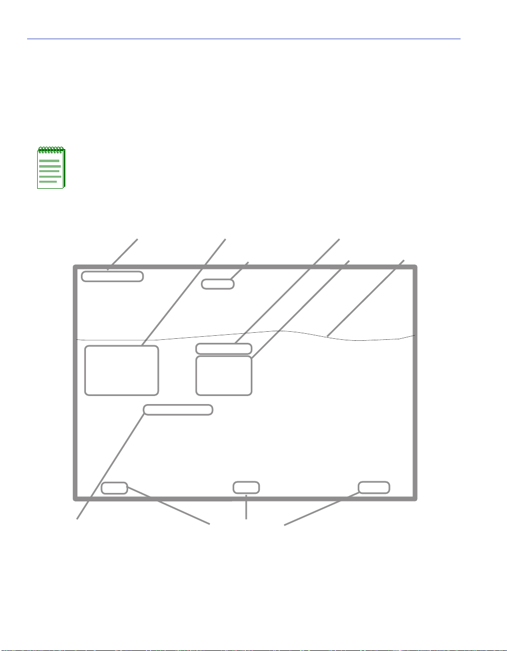
1.4 LOCAL MANAGEMENT SCREEN ELEMENTS
There are six types of screens used in Local Management: password, menu, statistics,
configuration, status, and warning screens. Each type of screen can consist of one to five basic
elements, or fields. Figure 1-1 shows an example of the fields in a screen. A description of each
field follows the figur e.
NOTE: The following definitions apply to most of the Local Management screens.
Exceptions to these definitions may occur in the Local Management screens of some
devices.
Figure 1-1 Example of a Local Management Screen
Event Message Field
Event Message Line
MAC Address:
IP Address:
Subnet Mask:
Default Gateway:
TFTP Gateway IP Addr:
Operational Mode: [802.1Q SWITCHING]
Clear NVRAM [NO]
IP Fragmentation [ENABLED]
Display Fields
Heading
XXXX-XX LOCAL MANAGEMENT
General Configuration
00-00-ID-00-00-00
0.0.0.0
255.255.0.0
NONE DEFINED
0.0.0.0
25042_14w
EXIT
Display Field
Input Fields
Firmware Revision: XX.XX.XX
BOOTPROM Revision: XX.XX.XX
Device Date:
Device Time:
Screen Refresh Time:
Screen Lockout Time:
Device Uptime XX D XX H XX M
10/11/97
14:23:00
30 sec.
15 min.
RETURNSAVE
See
Note
Selection Field
Note:
This shows the location of the cut away that is used in most of the screen graphics in this
document. The top portion of the screen is cut away to eliminate repeating the same
information in each graphic.The screen title is contained in its figure title.
1-4 Introduction
Command Fields
25042_14w
Page 27

Local Management Screen Elements
The following list explains each of the Local Management fields:
Event Message Field
This field briefly displays messages that indicate if a Local Management procedure was executed
correctly or incorrectly, that changes were saved or not saved to Non-Volatile Random Access
Memory (NVRAM), or that a user did not have access privileges to an application.
Table 1-1 describes the most common event messages. Event messages related to specific Local
Management applications are described with those applications throughout this manual.
Table 1-1 Event Messages
Message What it Means
SAVED OK One or more fields were modified, and saved to NVRAM.
NOT
SAVED--PRESS
SAVE TO KEEP
CHANGES
NOTHING TO
SAVE
Attempting to exit the LM screen after one or more fiel ds were
modified, but not saved to NVRAM.
The SAVE command was e x ecut ed, b ut nothi ng was sa v ed to NVRAM
because there were no configuration changes since the data was last
saved.
Heading Field
Indicates the model of the device.
Display Fields
Display fields cannot be edited. These fields may display information that never changes, or
information that may change as a result of Local Management operations, user selections, or
network monitoring information. In the sc reens shown in this guide, the cha racters in the display
fields are in plain type (not bold). In the field description, the field is identified as being
“read-only”.
Introduction 1-5
Page 28

Local Management Screen Elements
Input Fields
Input Fields require the entry of keyboard characters. IP addresses, subnet mask, default gateway
and device time are examples of input fields. In the screens shown in this guide, the characters in
the input fields are in bold type. In the field description, the field is identified as being
“modifiable”.
Selection Fields
Selection fields provide a series of possible values. Only applicable values appear in a selection
field. In the screens shown in this guide, the selections display within brackets and are in bold
type. In the f ield descript ion, t he f ield is identif ied as bei ng eithe r “selec table” wh en there are mor e
than two possible values, or “toggle” when there are only two possible values.
Command Fields
Command fields (located at the bottom of Local Management screens) are used to exit Local
Management screens, save Local Management entries, or navigate to another display of the same
screen. In the screens shown in this guide, the characters in t his field are all upper ca se and in bold
type. In the field description, the field is identified as being a “command” field.
1-6 Introduction
Page 29

Local Management Keyboard Conventions
1.5 LOCAL MANAGEMENT KEYBOARD CONVENTIONS
All key names appear as capital l etters i n this man ual. Table 1-2 explains the key board c on v ention s
and the key functions that are used.
Table 1-2 Keyboard Conventions
Key Function
ENTER Key
RETURN Key
These are selection keys that perform the same Local Management
function. For e xample, “Press ENTER” means t hat you can press ei ther
ENTER or RETURN, unless this manual specifically instructs you
otherwise.
ESCAPE (ESC) Key This key allows an escape from a Local Management screen without
saving changes. For example, “Press ESC twice” means the ESC key
must be pressed quickly two times.
SPACE Bar
BACKSPACE Key
These keys cycle through selections in s ome Loc al Mana gement f iel ds.
Use the SPACE bar to cycle forward through selections and use the
BACKSPACE key to cycle backward through selections.
Arrow Keys These are navigation keys. Use the UP-ARROW, DOWN-ARROW,
LEFT-ARROW, and RIGHT-ARROW keys to move the screen cursor.
For example, “Use the arrow keys” means to press whichever arrow
key moves the cursor to the desired field on the Local Management
screen.
DEL Key The DEL (Delete) key removes characters from a Local Management
field. For example, “Press DEL” means to press the Delete key.
Introduction 1-7
Page 30

1.6 GETTING HELP
For additional support related to the device or this document, contact Enterasys Networks using
one of the following methods:
World Wide Web http://www.enterasys.com/
Phone (603) 332-9400
Internet mail support@enterasys.com
FTP ftp://ftp.enterasys.com
Login anonymous
Password your email address
To send comments or suggestions concerning this document, contact the Technical Writing
Department via the following email address: TechWriting@enterasys.com
Make sure to include the document Part Number in the email message.
Before contacting Enterasys Networks, have the following information ready:
• Your Enterasys Networks service contract number
• A description of the failure
• A description of any action(s) already taken to resolve the problem (e.g., changing mode
switches, rebooting the unit, etc.)
• The serial and revision numbers of all involved Enterasys Networks products in the network
• A description of your network environment (layout, cable type, etc.)
• Network load and frame size at the time of trouble (if known)
• The device history (i.e., have you returned the device before, is this a recurring problem, etc.)
• Any previous Return Material Authorization (RMA ) numbers
Page 31

2
Local Management Requirements
This chapter provides the following information:
• Management Terminal Setup (Sec tion 2.1), which describes how to at tach a Local Manage ment
terminal to th e host device.
• Telnet Connections (Se ction 2.2), which provides guid eline s when using a Telnet connection to
access Local Management.
• Monitoring an Uninterruptible Power Supply (Section 2.3), which describes how to ma ke a
connection from the COM port to an Americ an Power Con v ersion (APC) Uninterruptible Po wer
Supply (UPS) device. This type of connection enables the SmartSwitch device to monitor the
power status in case of a power loss.
2.1 MANAGEMENT TERMINAL SETUP
Use one of the following systems to access Local Management:
• A PC or compatib le device running a VT series emulation software package
• A Digital Equipment Corporation VT100 type terminal
• A VT type t erminal running emul ation pr ograms for the Digi tal Equipment Corporat ion VT100
series
• A remote VT100 type terminal via a modem connection
• In-band via a Telnet connection
Local Management Requ irem ents 2-1
Page 32

Management Terminal Setup
2.1.1 Console Cable Connection
Use the Console Cable Kit provided with the SmartSwitch device to attach the management
terminal to the SmartSwitch device COM port as shown in Figure 2-1.
To connect the SmartSwitch device to a PC or compatible device running the VT terminal
emulation, proceed as follows:
1. Connect the RJ45 connector at one en d of th e cabl e (s uppli ed in the kit) to the COM p ort o n t he
SmartSwitch device.
2. Plug the RJ45 connector at the other end of the cable into the RJ45-to-DB9 adapter (supplied in
the kit).
3. Connect the RJ45-to-DB9 adapter to the communications port on the PC.
NOTE: If using a modem between the VT compatible device and the COM port of the
SmartSwitch device, use the appropriate connector included in the console cable kit.
Refer to the modem manufacturer’s information for proper operation and setup of the
modem.
The 2H252-25R SmartSwitch device is shown in Figure 2-1 as an example.
Figure 2-1 Management Terminal Connection
FAST ETHERNET WORKGROUP SWITCH
2H252-25R
LED
MODE
RX-TX
DPX-SPD
PWR
RESET
CPU
COM
RJ45-to-DB9
PC
2-2 Local Management Requirements
2
4
1
56789
3
2X 4X 6X 8X 10X 12X 14X 16X 18X 20X 22X 24X
12
10
14
11
13
20
16
18
19
15
17
RJ45 COM Port
UTP Cable
with RJ45 Connectors
PC Adapter
22
24
21
23
30691_02
Page 33

Management Terminal Setup
2.1.2 Management Terminal Setup Parameters
Table 2-1 lists the setup parameters for t he local management terminal.
Table 2-1 VT Terminal Setup
Display Setup Menu
Columns ->
Controls ->
Auto Wrap ->
Scroll ->
Text Cursor ->
Cursor Style ->
General Setup Menu
Mode ->
ID number ->
Cursor Keys ->
Power Supply ->
Communications Setup Menu
Transmit ->
Receive ->
XOFF ->
Bits ->
Parity ->
Stop Bit ->
Local Echo ->
Port ->
Transmit ->
Auto Answerback ->
80 Columns
Interpret Con trols
No Auto Wrap
Jump Scroll
Cursor
Underline Cursor Style
VT100, 7 Bit Controls
VT100ID
Normal Cursor Keys
UPSS DEC Supplemental
2400, 4800, 9600, 19200
Receive=Transmit
XOFF at 64
8 bits
No Parity
1 Stop Bit
No Local Echo
DEC-423, Data Leads Only
Limited Transmit
No Auto Answerback
Keyboard Setup Menu
Keys ->
Auto Repeat ->
Keyclick ->
Margin Bell ->
Warning Bell ->
Typewriter Keys
any option
any option
Margin Bell
Warning Bell
Local Management Requirements 2-3
Page 34

Telnet Connections
2.2 TELNET CONNECTIONS
Once the SmartSwitch device has a valid IP address, the user can establish a Telnet session from
any TCP/IP based node on the network. Telnet connections to the SmartSwitch device require the
community name passwords assigned in the SNMP Community Names Configuration screen.
For information about setting the IP address, refer to Section 4.2.
For information about assigning community names, refer to Section 4.4.
Refer to the instructions included with the Telnet application for information about establishing a
Telnet session.
If the SmartSwitch device is operating in the 802.1Q mode with configured VLANs, the
management station must be connected to a physical port on the device that is on the same VLAN
as the virtual Host Data Port. For more information about the virtual Host Data Port and the setup
information for remote mana gement in a device that is to be configured with VLANs, refer to
Section 12.8.
2.3 MONITORING AN UNINTERRUPTIBLE POWER SUPPLY
If the Smar tSwitch device is con nected to an American Power Conversion (AP C) Uninterruptible
Power Supply (UPS) device for protection against the loss of power, a connection from the
SmartSwitch device COM port to the UPS can be made to monitor the UPS power status. To use
the COM port for this purpose, it must be reconfigured to support the UPS connection using the
procedure described in Section 4.2.10. Refer to the UPS document ation for deta ils on how to
access the status information.
The Console Cable Kit provided with the SmartSwitch device is used to connect the UPS to the
SmartSwitch device COM port as shown in Figure 2-2. To connect the UPS device to the COM
port, proceed as follows:
1. Connect the RJ45 connector at one end of the cable to the COM p ort on the SmartSwitc h device.
2. Plug the RJ45 connector at the other end of the cabl e into th e RJ45-to-DB9 ma le (UPS) ad apter
(Enterasys Systems part number, 9372066).
3. Connect the RJ45-to-DB9 male (UPS) adapter to the female DB9 port on the rear of the UPS
device (r efer to the particular UPS d evice’ s user instruc tions for more specif ic informatio n about
the monitoring connection).
2-4 Local Management Requirements
Page 35

Monitoring an Uninterruptible Power Supply
Figure 2-2 Uninterruptible Power Supply (UPS) Connection
UPS Device
DB9 Port
RJ45-to-DB9
UPS Adapter
FAST ETHERNET WORKGROUP SWITCH
2H252-25R
LED
MODE
RX-TX
DPX-SPD
RESET
COM
2
1
2X 4X 6X 8X 10X 12X 14X 16X 18X 20X 22X 24X
PWR
CPU
4
3
56789
10
16
12
14
18
15
11
13
17
RJ45 COM Port
UTP Cable
with RJ45 Connectors
22
24
20
21
23
19
30691_03
Local Management Requirements 2-5
Page 36

Page 37

3
Accessing Local Management
This chapter provides information about the following:
• Nav igating through t he Local Management screen hierarch y for each mode of operation (802.1Q
Switching and SecureFast VLAN) (Section 3.1).
• Accessing the Password screen to enter a Local Management session (Section 3.2).
• Accessing the Device Menu screen and its menu items to gain access to other screens for
configuring the switch, obtaining operating statistics, and obtaining access to network tools
(Section 3.3).
• Accessing the De vic e Menu scree n and it s menu it ems to g ain a ccess t o the L ocal M anagement
screens including the security screens. (Section 3.5).
• Security methods (Section 3.5).
• Accessing the Passwords (Section 3.6) and Radius Configuration (Section 3.7) screens. These
screens allow you to configure additional security by limiting access to Local Management
according to local access policy and remote ly using the RA DIUS Client feature.
Accessing Local Managemen t 3-1
Page 38

Navigating Local Management Screens
3.1 NAVIGATING LOCAL MANAGEMENT SCREENS
The SmartSwitch device Local Management application consists of a series of menu screens.
Navigate through Local Management by selecting items from the menu screens.
The SmartSwitch device supports two modes of switch operation. The switching modes are as
follows:
• 802.1Q SWITCHING (IEEE 802.1Q port based VLANs)
• SECURE FAST VLAN (SecureFast switching)
The switch operational mode is set in the General Configuration screen (Section 4.2). Depending
on the Operational Mode set f or the device, the hierarchy of the Loc al Manage ment sc ree ns differs
as shown in Figure 3-1 and Figure 3-2. Refer to the appropriate figure that relates to the
Operational Mode set for the device to see the applicable Local Management screen hierarchy.
NOTE: At the beginning of each chapter, a section entitled “Screen Navigation Path”
shows the navigation path to the first screen described in the chapter.
3-2 Accessing Local Management
Page 39

Navigating Local Management Screens
Figure 3-1 802.1Q Switc hing Mode, LM Screen Hierarchy
Device Configuration Menu
General Configuration
SNMP Configuration Menu
System Resources Information
FLASH Download Configuration
SNMP Community Names Configuration
SNMP Traps Configuration
Access Control List
Password
Device
Menu
Port Configu ration Menu
802.1 Configuratio n Men u
Switch Configuration
802.1Q VLAN
Configuration Menu
802.1 Priority
Configuration Menu
Port Priority
Configuration
Advanced Port
Priority
Configuration
Transmit Queues
Configuration
Priority Classification
Configuration
GARP Configuration Menu
Rate Limiting Configuration
Device VLAN
Configuration
Port Assignment
Configuration
Port Filtering
Configuration
VLAN Forwarding
Configuration
VLAN Classification
Configuration
Protocol Port
Configuration
Protocol Port
Configuration
GARP Configuration
GMRP Configuration
Ethernet Interface
Configuration
Ethernet Port
Configuration
HSIM/VHSIM
Configuration
Redirect Configuration
Menu
Port Redirect
Configuration
VLAN Redirect
Configuration
* SmartTrunk
Configuration
Broadcast
Suppression
Configuration
Layer 3 Extensions Menu
Device Statistics
Menu
Network Tools
Security
* Refer to the SmartTrunk User’s Guide for the screen hierarchy.
Switch Statistics
Interface Statistics
RMON Statistics
IGMP/VLAN Configuratio n
Pass words
Radius Configuration
Accessing Local Management 3-3
Page 40

Navigating Local Management Screens
Figure 3-2 SecureFast VLAN Mode, LM Screen Hierarchy
Device Configuration Menu
General Configuration
SNMP Configuration Menu
System Resources Information
FLASH Download Configuration
SNMP Community Names Configuration
SNMP Traps Configuration
Ethernet Interface
Configuration
Ethernet Port
Configuration
HSIM/VHSIM
Configuration
Port Redirect
Configuration
Password
Device
Menu
Port Configuration Menu
Device Statistics
Menu
Network Tools
Interface Statistics
RMON Statistics
3.1.1 Selecting Local Management Menu Screen Items
Select items on a menu screen by performing the following steps:
1. Use the arrow keys to highlight a menu item.
2. Press ENTER. The selected menu item displays on the screen.
3.1.2 Exiting Local Management Screens
There are two ways to exit the Local Management (LM) screens.
Using the Exit Command
To exit LM using the EXIT screen command, proceed as follows:
30691_83
30691_83
1. Use the arrow keys to highlight the EXIT command at the bottom of the Local Management
screen.
2. Press ENTER. The Local Management Password screen displays and the session ends.
3-4 Accessing Local Management
Page 41

Navigating Local Management Screens
Using the RETURN Command
To exit LM using the RETURN command, proceed as follows:
1. Use the arrow keys to highlight t he RETURN command at the botto m of the Local Management
screen.
2. Press ENTER. The previous screen in the Local Management hierarchy displays.
NOTE: The user can also exit Local Management screens by pressing ESC twice. This
exit method does not warn about unsaved changes and all unsaved changes are lost.
3. Exit from Local Management by repeating steps 1 an d 2 until th e De vic e Menu scre en displ ays.
4. To end the LM session, use the arrow keys to highlight the RETURN command at the bottom
of the Device Menu screen.
5. Press ENTER. The Local Management Password screen displays and the session ends.
3.1.3 Using the NEXT and PREVIOUS Commands
If a particul ar Local Mana gement screen has more than one screen to display its information, the
NEXT and PREVIOUS commands are used to navigate between its screens.
To go to the next or previous display of a screen, proceed as follows:
1. Highlight the applicable NEXT or PREVIOUS command at the bottom of the screen.
2. Press ENTER. The screen displays.
3.1.4 Using the CLEAR COUNTERS Command
The CLEAR COUNTERS command is used to t empo raril y rese t all counter s o f a scre en to ze ro to
allow the user to observe counter activity over a period of time. To reset the counters, perform the
following st eps:
1. Use the arrow ke ys to highlight the CLEAR COUNTERS command.
2. Press ENTER, the counters are reset to zero.
Accessing Local Management 3-5
Page 42

Password Screen
3.2 PASSWORD SCREEN
When to Use
To start a Local Management session. Local Management is controlled through the Local
Management Password screen shown in Figure 3-3. Whenever a connection is made to the
SmartSwitch device the Local Management Password screen displays. Before continuing, you
must enter a password (communi ty na me ), whi ch is compar ed to the pr eviously stored passwords.
The lev el o f access all o wed the u ser d epen ds on t he pa ssw ord. To set or chan ge p assw ord s, ref er t o
Section 4.4.
How to Access
1. Turn on the terminal. Press ENTER (this may take up to four times, because the COM port of
the SmartSwitch device auto-se nses the baud rate of the terminal) until the Local Management
Password screen displays. Figure 3-3 shows the Password screen.
Screen Example
Figure 3-3 Local Management Password Screen
(c) Copyright Enterasys Networks, Inc. 2001
Device Serial Number: XXXXXXXXX
Device Hardware Revision: XX
Device Firmware Revision: XX.XX.XX
Device BOOTPROM Revision: XX.XX.XX
SecureFast VLAN Revision: XX.XX.XX
Enter Password:
3-6 Accessing Local Management
xxxxx-xx LOCAL MANAGEMENT
Enterasys Systems, Incorporated
P.O.Box 5005
Rochester, NH 03866-5005 USA
(603) 332-9400
30692_04
Page 43

Password Screen
2. Enter the Password and press ENTER. The default super-user access password is “public” or
press ENTER.
NOTE: The password is one of the community names specified in the SNMP
Community Names Configuration screen. Access to certain Local Management
capabilities depends on the degree of access accorded that community name. Refer to
Section 4.4.
If an invalid password is entered, the terminal beeps and the cursor returns to the
beginning of the password entry field.
Entering a valid password causes the associated access level to display at the bottom of
the screen and the Device Menu screen to display.
If no activity occurs for a preset period of time, the Local Management Password screen
redisplays and the password has to be reentered.
Accessing Local Management 3-7
Page 44

Device Menu Screen
3.3 DEVICE MENU SCREEN
When to Use
To access the three major menu screens of Local Management to configure the SmartSwitch
device, obtain operating statistics, access the network tools command set, and set the security
access policy for the switch.
How to Access
Enter a vali d passw or d in the Local Ma nage ment P assw or d scree n as de scri bed in Section 3.2, and
press ENTER. The Device Menu screen, Figure 3-4, displays.
Screen Example
Figure 3-4 Device Menu Screen
DEVICE CONFIGURATION
DEVICE STATISTICS
NETWORK TOOLS
SECURITY
NOTE: If the terminal is idle for several minutes, the Local Management Password
screen redisplays and the session ends. This idle time can be changed in the General
Configuration screen described in Section 4.2.
3-8 Accessing Local Management
EXIT
RETURN
30692_05
Page 45

Menu Descriptions
Refer to Table 3-1 for a functional description of each menu item.
Table 3-1 Device Menu Screen Menu Item Descriptions
Menu Item Screen Function
Device Menu Screen
DEVICE
CONFIGURATION
MENU
Provides access to the Local Management screens that are used to
configure the SmartSwitch device and also provides access to the Port
Configuration Menu, 802.1 Configuration Menu, and Layer 3
Extensions Menu screens.
The Port Confi guration Me nu screen pro vides a ccess to the screens that
are used to set operating parameters specific to each port.
For more information about the Device Configuration Menu screen,
refer to Chapter 4.
DEVICE
STATISTICS
MENU
NETWORK
TOOLS
Provides access to screens used to obtain SmartSwitch device,
interface, a nd RMON statistics information. For details, refer to
Chapter 10.
The Network Tools function resides on the switch and consists of that
commands that allow you to access and manage the SmartSwitch
device and also Telnet to other de vices. Chapter 11 explains how to use
the Network Tools utility.
SECURITY Provides access to the Passwords and the Radius Configuration
screens.
The Passwor ds screen al lo ws you to se t a login pass word f or the de vice
according to access policy (read-only, read-write, and super-user). A
different password can be set for each access policy.
To prevent clearing the passwords, hardware switch 8 on the board of
the device can be disabled using this screen. For an overview of the
security available on this switch, refer to Section 3.4.
The Radius Configuration screen allows you to configure the Radius
Client on the switch to restrict access to the Local Management screens
via Telnet or the web. You can also program this function using the
“radius” command described in Chapter 11.
For more information about the Passwords screen, refer to Section 3.6.
Accessing Local Management 3-9
Page 46

Overview of Security Methods
3.4 OVERVIEW OF SECURITY METHODS
Three security met hods are a v a ilabl e to co ntro l whic h users are al lowed access to the switch’s host
to monitor the configuration and control of the switch.
• Host Access Control Lis t (ACL) – allows only the defi ned list of IP Address es to co mmunic ate
with the host for Telnet, WebView (HTTP) and SNMP. To set up these parameters refer to the
Host Access Control List (ACL) screen described in Section 4.6.
• Switch Local Management Application Password – allows three levels of SNMP local
management access via ser ial console or telnet (super user, read-write and read-only) using t he
the Password screen described in Section 3.2. The three levels of remote SNMP management
access are set using the SNMP Community Names Configuration screen described in
Section 4.4.
• Host Access Control Authentication (HA CA) – authent icates user access o f T elnet management,
console local managemen t and W ebV iew via a ce ntral Radius Client/Serv er application usin g the
Password screen described in Section 3.6. For an overview of HACA and a description of how
to set the switch acce ss pol ic y us ing t he Ra diu s Conf i gurat ion s creen , ref er to Section 3.4.1 and
Section 3.7.
3.4.1 Host Access Control Authentication (HACA)
T o use HA CA, the embe dded Radius Client on the switch must be conf igured to co mmunicate with
the Radius Server, and the Radius Server must be configured with the password information. The
Enterasys implementation uses Funk Software Steel-Belted Radius server software, This software
provides the ability to centralize the Authentication, Authorization, and Accounting (AAA) of the
network resources. For more information, refer to the RFC 2865 (Radius Authentication) and
RFC 2866 (Radius Accounting) for a description of the protocol.
Each switch has its own Radius Client. The client can be configured via
• the Radius Configuration screen described in Section 3.7, or
• the Network Tools Command Line Interface (CLI) using the “radius” and “access” commands
described in Chapter 11.
The IP address of the Radius Server (and, if available, the secondary server IP address) and
shared secret text string must be configured on the Radius Client. The client can use either the
Password Authentication Protocol (PAP) or the Challenge Handshake Authentication Protocol
(CHAP) to communicate the user name and encrypted password to the Radius Server.
3-10 Accessing Local Management
Page 47

Overview of Security Methods
On the Radius Server, each user is configured with the following:
•name
• password
• access level
The access level can be set to one of the following levels for each user name:
• super-user
• read-write
• read-only
To support multiple access levels per user name, it involves sending back a different “FilterID”
attribute using some server feature to differentiate between the same user name with different
prefixes/suffixes. For example, “username@engineering” and “username@home” could each
return different access levels.
NOTE: This is a server-dependent feature.
Only one password is allowed per access level. This enables the Radius Server to track the users
accessing the switch host and how long they used the host application.
All radius values, except the server IPs and shared secrets, are assigned reasonable default values
when radius is installed o n a new switch. The defaults are as fo llows:
• Client, disabled
• Timeout, 20 seconds
•Retry, 3
• Primary and secondary Authentication ports: 1812 (per RFC 2865)
• Primary and secondary Accounting ports: 1813 (per RFC 2866)
• Last-resor t for local and remote is chal lenge
If only one server is confi gured, it must be th e primary se rver. It is not necessary to rebo ot after the
client is reconfigured.
Accessing Local Management 3-11
Page 48

Overview of Security Methods
The client cannot be enabled unless the primary server is configured with at least the minimum
configuration information.
NOTE: The minimum additional information that must be configured to use a server is
its IP and Shared Secret.
When the Radius Client is active on the switch, you are prompted by an authorization screen for a
user login name and password when attempting to access the host IP address via the local console
LM, Telnet to LM, or WebView application. The embedded Radius Client encrypts the
information entered by the user and sends it to the Radius Server for validation. Then the server
returns a yes or no response back to the client, allowing or denying the user to access the host
application with the proper access level.
An access-accept response returns a message USER AUTHORIZATION = <ACCESS LEVEL>
for 3 seconds and then the main screen of the application is displayed. An access-denied response
causes an audible “beep” and the screen to return to the user name prompt.
If the Radius Client is unable to receive a response from the Radius Server, because the Radius
Server is down or inaccessible, the Radius Client will time out to a default value of 20 seconds.
If the serv er r eturns an “access-accept” response (the user successfully au thenticated), it must also
return a Radius “FilterID” attribute containing an ASCII string with the following fields in the
specified format:
“Enterasys:version=V:mgmt=M:policy=N”
Where:
V is the version number (currently V=1)
M is the access level for management, one of the following strings:
“su” for super-user access
“rw” for read-write access
“ro” for read-only access
N is the policy profile number (see the policy profile MIB)
NOTES:
Quotation marks (“ ”) are not part of the strings. They are used for clarification only.
If the FilterID attribute is not returned, or the “mgmt” field is absent or contains an
unrecognizable value, access is denied.
Policy profiles are not yet deployed and the “policy=N” part may be omitted.
3-12 Accessing Local Management
Page 49

Security Menu Screen
The secondary server is always consulted if it is configured. Note that the minimum additional
information that must be configured to use a server is its IP and shared secret.
A backup secondary server is always consulted if it has been configured with its IP and Shared
Secret. If communication is lost to all servers, and the user is connected to the local console serial
port, the authorization screen will change to allow access to the switch by using the Local
Management Module password.
If the user is connected remotely via telnet or WebView, the switch will continue to deny access
until communica tion wit h the Rad ius Serv er is ope rational again . Optio nally, if the swit ch has been
configured to allow remote access, the switch can be configured to use the Local Management
Module password in the event of a Radius failure.
NOTE: Accounting by Radius is not initially supported and will be performed in a future
release of the firmware.
3.5 SECURITY MENU SCREEN
Screen Navigation Paths
Password > Device Menu > Security
When to Use
To access the Passwords and Radius Configuration screens. These screens allow you to configure
additional limited access to Local Management.
How to Access
Use the arrow keys to highlight the SECURITY menu item on the Device Menu screen and press
ENTER. The Security Menu screen, Figure 3-5, displays.
Accessing Local Management 3-13
Page 50

Security Menu Screen
Screen Example
Figure 3-5 Security Menu Screen
PASSWORDS
RADIUS CONFIGURATION
EXIT
RETURN
Menu Descriptions
Refer to Table 3-2 for a functional description of each menu item.
Table 3-2 Security Menu Screen Descriptions
Menu Item Screen Function
PASSWORDS Used to set the Locally Administered Passwords (super user,
read-write, and read-only) to access the device according to an access
policy. For details, refer to Section 3.6.
RADIUS
CONFIGURATION
Used to configur e t he Radius Client Parameters on the swi tc h, pr imar y
server, and secondary server. For details, refer to Section 3.7.
3559_66w
3-14 Accessing Local Management
Page 51

Passwords Screen
3.6 PASSWORDS SCREEN
Screen Navigation Path
For MATRIX E7 chassis:
Password > > Device Menu > Security > Passwords
When to Use
To provide addition al s ecu rity b y usi ng login pass wo rds a ssoci ate d to an a cce ss po lic y. This screen
allows the use of passwords to provide three levels of Local Management access (super-user,
read-write and read-onl y) via s erial console o r telne t conn ection. T his s creen is also us ed to di sable
the function of hardware switch 8 to prevent the clearing of the login passwords.
How to Access
Use the arrow keys to highlight the PASSWORDS menu item on the Security Menu screen and
press ENTER. The Module Login Passwords screen, Figure 3-6, displays.
Screen Example
Figure 3-6 Module Login Passwords Screen
Password
* * * * * * * *
* * * * * * * *
* * * * * * * *
Switch 8 [ENABLED]
EXIT
Access Policy
read-only
read-write
super-user
RETURNSAVE
4046-33
Accessing Local Management 3-15
Page 52

Passwords Screen
Field Descriptions
Refer to Table 3-3 for a functional description of each screen field.
Table 3-3 Module Login Passwords Screen Field Descriptions
Use this field… To…
Password
(Modifiable)
Access Policy
(Read-only)
Switch 8
(Toggle)
Enter the password used to access the device according to an access
policy.
See the access given each password. Possible selections are as follows:
read-only This password allows read-only access to the Local
Management, and excludes access to
security-protected fields of read-write or super-user
authorization.
read-write This password allows read and write access to Local
Management, excluding security protected fields for
super-user access only.
super-user This password permits read-write access to Local
Management and allows the user to change all
modifiable p arameters inclu ding community names , IP
addresses, traps, and SNMP objects.
Enable or disable the function of hardware switch S8 on the main
board of the device. When set to ENABLED, S8 can be used to clear
the password. When set to DISABLED, S8 cannot be used to clear the
password. The default is Enable.
3-16 Accessing Local Management
Page 53

RADIUS Configuration Screen
3.6.1 Setting the Login Password
To set passwords and disable the function of switch S8 so that the password cannot be cleared,
proceed as follo ws:
1. Use the arrow keys to highlight the appropriate Password field. A different password can be
assigned to each Access Policy.
2. Press ENTER.
3. To disable the function of switch S8 so the passwords cannot be cleared, use the arrow keys to
highlight the Switch 8 field.
4. Press the SPACE bar to select DISABLED.
5. To save the settings, press ENTER. The message “SAVED OK” displa ys at the top o f the screen.
3.7 RADIUS CONFIGURATION SCREEN
When to Use
To configure the Radius client in the switch to restrict access to the management functions of the
Local Management screens, by way of the COM port or network TELNET connection.
NOTE: The configuration and Enable State of the Radius Client will be stored in
NVRAM and loaded on power-up. If the client is properly configured and enabled, the
platform will create the Radius Client and enable it at boot time, superseding legacy
authentication. Otherwise, the legacy authentication becomes operational.
Radius Client parameters can also be set using the Network Tools screen described in
Chapter 11.
This screen allows you to set the necessary parameters to centralize the Authentication,
Authorization, an d Acc oun ti ng of the network resources. F o r information about Radius Client an d
how it functions, refer to Section 3.4 and Section 3.4.1.
Accessing Local Management 3-17
Page 54

RADIUS Configuration Screen
How to Access
Use the arrow keys to highlight the RADIUS CONFIGURATION menu item on the Security
Menu screen and press ENTER. The RADIUS Configuration screen, Figure 3-7, displays.
Screen Example
Figure 3-7 Radius Configuration Screen
Primary Server
IP: 172.29.80.90
Secret: ********************************
Auth Port: 1645
Acct Port: 1646
Secondary Server
IP: 134.141.40.104
Secret: ********************************
Auth Port: 1645
Acct Port: 1646
Local Remote
Timeout: 15 Last Resort Action: [ACCEPT] [CHALLENGE]
Retries: 03 Radius Client: [ENABLED]
SAVE EXIT RETURN
Field Descriptions
Refer to Table 3-4 for a functional description of each screen field.
Table 3-4 Radius Configuration Screen Field Descriptions
Use this field… To…
IP
(Modifiable)
Secret
(Modifiable)
3-18 Accessing Local Management
Enter the IP address (in decimal-dot format) of the primary and
secondary servers being configured for the RADIUS function.
Enter a secret string of characters or the primary and secondary server
(16 characters are recommended as per RFC 2865). The maximum is
32 characters).
Page 55

RADIUS Configuration Screen
Table 3-4 Radius Configuration Screen Field Descriptions (Continued)
Use this field… To…
Auth Port
(Modifiable)
Acct Port
(Modifiable)
Timeout
(Modifiable)
Retries
(Modifiable)
Last Resort
Action/Local
(Selectable)
Last Resort
Action/Remote
(Toggle)
Enter the number of the Authorization U DP Port for the Primary and
Secondary server.
Enter the number of the Accounting UDP Port for the Pr imary and
Secondary server.
Enter the maximum time in second s to establish contact with the
Radius Server before timing out.
Enter the maximum number of attempts (1…N) to contact the Radius
Server before timi ng out.
Accept, Challenge, and Reject, which do the following:
ACCEPT: Allows local access (via COM port) at the super-user
level with no further attempt at authentication.
CHALLENGE: Reverts to local module (legacy) passwords.
REJECT: Does not allow local access.
For more details, refer to Section 3.7.1.
To set local and remote servers, refer to Section 3.7.2.
Accept, Challenge, and Reject, which do the following:
ACCEPT: Allows remote access (via Telnet or WebWiew) at the
super-user level with no further attempt at authenti cation.
Radius Client
(Toggle)
CHALLENGE: Reverts to local module (legacy) passwords.
REJECT: Does not allow remote access.
For more details, refer to Section 3.7.1.
To set local and remote servers, refer to Section 3.7.2.
Enable or disable clie nt status.
Accessing Local Management 3-19
Page 56

RADIUS Configuration Screen
3.7.1 Setting the Last Resort Authentication
The RADIUS client can be configured to use primary and secondary s er v e rs. If the primary server
does not respond within the specified number of retries during the specified time-out period, the
client will then attempt to authenticate using the secondary server. If the secondary server also
does not respond, then the client returns a time-out condition.
The “last resort” platform action in case of RADIUS server time-out for both local and remote
access is selectable for each type of access:
• Local login via the COM port.
• Remote login via a remote network TELNET connection.
3.7.2 Setting the Local and Remote Servers
Before setting th e parameter s, refe r to Sec tion 3.4.1 and Section 3.7.1 for a better understan ding of
Radius Servers and Last Resort Authentication. To set the local and remote server, proceed as
follows:
1. Use the arrow keys to highlight the IP fie ld and enter the IP address (in decimal-dot for m at) of
the primary and secondary servers being configured for the RADIUS function.
2. Highlight the Auth Port field and enter the number of the Authorization UDP Port for the
Primary and Secondary server.
3. Highlight the Acct Port f ield and ent er the number of the Acco unting UDP Port for the Pri mary
and Secondary server.
4. Highlight the Secret field and enter a secret string of characters or the primary and secondary
server (16 characters are recommended as per RFC 2865. The maximum is 32 characters).
5. Highlight the Retries field and enter the desired maximum number of attempts (1 …N) to contact
the Radius Server before timing out.
6. Highlight the Timeout field and enter the maximum time in seconds to establish contact with
the Radius Server before timing out.
7. Highlight the Last Resort Action/Local field and select ACCEPT, CHALLENGE, or
REJECT to allow l oca l acc ess a t th e super- user level with no furt her attempt a t aut henti cati on;
revert local module to (legacy) passwords, or not allow local access.
8. Highlight the Last Resort Act ion/Remote field selec t ACCEPT, CHALLENGE, or REJECT
to allow remote access at the super-user level with no further attempt at authentication, revert
remote module to (legacy) passwords, or not allow remote access, respectively.
9. Use the arrow keys to highlight the SAVE command and press ENTER to save your settings.
3-20 Accessing Local Management
Page 57

4
Device Configuration Menu Screens
This chapter describes the Device Configuration Menu screen and the following screens that may
be selected:
• General Configuration screen (Section 4.2)
• SNMP Configuration Menu screen (Section 4.3)
• SNMP Community Names Configuration screen (Section 4.4)
• SNMP Traps Configuration screen (Section 4.5)
• Access Control List screen (Section 4.6)
• System Resources Information screen (Section 4.7)
• FLASH Download Configuration screen (Section 4.8)
• Port Configuration Menu screen (Chapter 5)
• 802.1 Configuration Menu screen (Chapter 6)
• Layer 3 Extensions Menu (Chapter 9)
Screen Navigation Path
Password > Device Menu > Device Configuration Menu
Device Configuration Menu Screens 4-1
Page 58

Device Configuration Menu Screen
4.1 DEVICE CONFIGURATION MENU SCREEN
When to Use
To access a series of Local M anagemen t scr eens u sed to es tabli sh an Access Control List (ACL) to
provide additio nal security, configure and monitor operating paramete rs, modify SNMP
community names, set SNMP traps, configure switch parameters, and configure the SmartSwitch
device ports.
How to Access
Use the arrow keys to highlight the DEVICE CONFIGURATION MENU item on the Device
Menu screen, and press ENTER. The Device Configuration Menu screen, Figure 4-1, displays.
Screen Example
Figure 4-1 Device Configuration Menu Screen
GENERAL CONFIGURATION
SNMP CONFIGURATION MENU
SYSTEM RESOURCES INFORMATION
FLASH DOWNLOAD CONFIGURATION
PORT CONFIGURATION MENU
802.1 CONFIGURATION MENU
LAYER 3 EXTENSIONS MENU
4-2 Device Configuration Menu Screens
EXIT
RETURN
30691_07
Page 59

Device Configuration Menu Screen
Menu Descriptions
Refer to Table 4-1 for a functional description of each menu item.
Table 4-1 Device Configuration Menu Screen Menu Item Descriptions
Menu Item Screen Function
GENERAL
CONFIGURATION
SNMP
CONFIGURATION
MENU
SYSTEM
RESOURCES
INFORMATION
FLASH
DOWNLOAD
CONFIGURATION
PORT
CONFIGURATION
MENU
802.1
CONFIGURATION
MENU
Used to monitor and configure the SmartSwitch device operating
parameters. For details, refer to Section 4.2.
Used to access the SNMP Community Names Configuration, SNMP
Traps Configuration, and Access Control List screens. These screens
are used to modify SNMP community names, set SNMP traps and
provide additional security while managing the devices.
For details, refer to Section 4.3.
Displays the CPU type used in the device and its operating speed;
displays the size of each memory system used (FLASH memory,
DRAM and NVRAM) in the device and the unused portion of each
memory; and displays the current CPU (switch) utilization and the
peak switc h utilization. For details, refer to Section 4.7.
Used to force the SmartSwitch device to download a new image file
from a TFTP server to its FLASH memory. For details, refer to
Section 4.8.
Used to select the screens for configuring the SmartSwitch device
ports. For details, refer to Section 5.1.
Displays only if the SmartS witch de vice has b een conf igured to oper ate
as an IEEE 802.1Q switch as described in Section 4.2.9. When
selected, the 802.1 Configuration Menu screen provides access to the
Switch Configuration screen, the 802.1Q VLAN Configuration Menu
screen, the 802.1 Priority Configuration Menu screen, the GARP
Configuration Menu screen, and the Rate Limiting Configuration
screen. For details, refer to Section 6.1.
NOTE: The 802.1 Configuration Menu and associated screens
display only if the SmartSwitch device has been configured to
operate in the 802.1Q switch mode.
Device Configuration Menu Screens 4-3
Page 60

General Configuration Screen
Table 4-1 Device Configuration Menu Screen Menu Item Descriptions (Continued)
Menu Item Screen Function
LAYER 3
EXTENSIONS
MENU
Provides acce ss to the I GMP/V LAN Conf igur ation screen to conf i gure
ports and VLANs to operate according to the Internet Group
Management Protocol (IGMP). For details, refer to Chapter 9.
NOTE: The Layer 3 Extensions Menu and IGMP/VLAN
Configuration screens display only if the SmartSwitch device
has been configured to operate in the 802.1Q switch mode.
4.2 GENERAL CONFIGURATION SCREEN
When to Use
To set the system date and time, IP address and subnet mask, the default gateway, the TFTP
gateway IP address, and the operational mode. This screen can also be used to clear the NVRAM,
set the screen refresh time, the screen lockout time, the IP fragmentation, the COM port
configuration, and monitor the total time (uptime) that the device has been running.
How to Access
Use the arrow keys to highlight the GENERAL CONFIGURATION menu item on the Device
Configuration Menu screen and press ENTER. The General Configuration screen, Figure 4-2,
displays.
4-4 Device Configuration Menu Screens
Page 61

Screen Example
Figure 4-2 General Configuration Screen
General Configuration Screen
MAC Address:
IP Address:
Subnet Mask:
Default Gateway:
TFTP Gateway IP Addr:
Operational Mode: [802.1Q SWITCHING]
Com: [ENABLED] Application: [LM]
Clear NVRAM: [NO]
00-00-ID-00-00-00
0.0.0.0
255.255.0.0
NONE DEFINED
0.0.0.0
IP Fragmentation: [ENABLED]
EXIT
Device Date:
Device Time:
Screen Refresh Time:
Screen Lockout Time:
Device Uptime XX D XX H XX M
Field Descriptions
Refer to Table 4-2 for a functional description of each screen field.
.
Table 4-2 General Configuration Screen Field Descriptions
Use this field… To…
10/11/1999
14:23:00
30 sec.
15 min.
RETURNSAVE
30691_08
MAC Address
(Read-Only)
IP Address
(Modifiable)
See the base physical address of the SmartSwitch device.
See the IP address for the SmartSwitch device. To set the IP address,
refer to Section 4.2.1. The IP address can also be set through Runtime
IP Address Discovery.
Runtime IP A ddress Discovery enables the SmartSw itch device to
automatically accept an IP address from a Boot Str ap Protocol (BootP)
server on the network without requiring a user to enter an IP address
through Local Management.
Device Configuration Menu Screens 4-5
Page 62

General Configuration Screen
Table 4-2 General Configuration Screen Field Descriptions (Continued)
Use this field… To…
Subnet Mask
(Modifiable)
Default Gateway
(Modifiable)
TFTP Gateway IP
Addr
(Modifiable)
Device Date
(Modifia ble)
Device Time
(Modifia ble)
Screen Refresh
Time
(Modifiable)
See the subnet mask for the SmartSwitch device. A subnet mask
“masks out” the netwo rk bits of the IP addres s by setti ng the bit s in the
mask to 1 when the network treats the corresponding bits in the IP
address as part of the network or subnetwork address, or to 0 if the
corresponding bit identifies the host. When an IP address is entered in
the IP Address field, the Subnet Mask field automatically changes to
the default subnet mask for that IP address. For details about how to
change the subnet mask from its default value, refer to Section 4.2.2.
See the defaul t gateway for the SmartSwitch device. This field is not
defined unt il a n appro pri ate value is entered. For deta ils a bout wh y a nd
how to set the Default Gateway, refer to Section 4.2.3.
See the TFTP Gateway IP address for the SmartSwitch device. To set
the TFTP Gateway IP address, refer to Section 4.2.4.
Enter a new device date. To enter a new date, refer to Section 4.2.5.
Enter a device new time. To enter a new time, refer to Section 4.2.6.
Enter a new device time. This setting determines how frequently (in
seconds) information is updated on the screen. To enter the refresh
time, refer to Section 4.2.7.
Screen Lockout
Time
(Modifiable)
Enter a new lo ckout t ime. This is max imum number of minutes that the
Local Management application displays a screen while awaiting input
or action from a user. For example, if the number 5 is entered in this
field, the us er has up to f ive minutes to respond to each of t he sp ecif i ed
device’s Local Management screens.
In this example, after five minutes of no input or action, the terminal
“beeps” five times, the Local Management application terminates the
session, and the display returns to the Local Management Password
screen.
To ent er the screen lockout time, refer to Section 4.2.8.
4-6 Device Configuration Menu Screens
Page 63

General Configuration Screen
Table 4-2 General Configuration Screen Field Descriptions (Continued)
Use this field… To…
Device Uptime
(Read-Only)
Operational Mode
(Toggle)
Com
(Toggle)
Application
(Toggle)
See the total time that the device has been operating.
Set the SmartSwitch de vice to operate as eithe r an IEEE 802.1Q s witch
(802.1Q SWITCHING option) or as a SecureFast switch (SECURE
FAST VLAN option).
In the 802.1Q SWITCHING mode ( t he default mode of operation), the
SmartSwitch device functions like an 802.1D switch until IEEE
802.1Q VLANs are configured.
When the operational mode is set to SECURE FAST VLAN, the
SmartSwitch device acts as a SecureFast switch. With the SecureFast
VLAN Manager software, the SmartSwitch device is able to increase
its switching functionality by creating and maintaining SecureFast
Virtual LANs (VLANs).
For details on how to select the Operational Mode, refer to
Section 4.2.9.
Enable or disable the COM port. The selection toggles between
ENABLED and DISABLED. The default is ENABLED. For details
about setting up the COM port, refer to Section 4.2.10.
Set the application that the COM port will support. The field toggles
between LM (Local Management) and UPS (Uninterruptible Power
Supply). The default is LM.
Clear NVRAM
(Toggle)
The UPS setting allows the COM p ort to be used to monitor an
American Power Conversion (APC) Uninterruptible Power Supply
(UPS).
The baud rate setting for LM is automatically sensed. For UPS, the
baud rate is automatically set to 2400.
For details about how to configure the COM port for various
applications, refer to Section 4.2.10.
Reset NVRAM to the factory default settings. All user-entered
parameters, such as IP address and Community Names, are then
replaced with the SmartSwitch device default configuration settings.
For details, refer to Section 4.2.11.
Device Configuration Menu Screens 4-7
Page 64

General Configuration Screen
Table 4-2 General Configuration Screen Field Descriptions (Continued)
Use this field… To…
IP Fragmentation
(Toggle)
Enable or disable IP Fragmentation. The default setting for this field is
ENABLED.
If the SmartSwitch device is to be bridge d to an FDDI ring using an
HSIM-F6, IP Fragmentation should be enabled. If IP Fragmentation is
disabled, all FDDI frames that exceed the maximum Ethernet frame
size are discarded if they are destined for a small frame size port, such
as Ethernet, WAN, Gigabit Ethernet, and ATM (at the time of this
printing). Even if IP Fragmentation is disabled, large frames will still
be forwarded out the ports if necessary. Check the release notes for
changes. For details on ena bling IP Fragme ntation, refer to
Section 4.2.12.
4.2.1 Setting the IP Address
To set the IP address, perform the following steps:
1. Use the arrow keys to highlight the IP Address field.
2. Enter the IP address into this field using Dotted Decimal Notation (DDN) format.
For example: nnn.nnn.nnn.nnn
3. Press ENTER. If the IP address is a valid format, the cursor returns to the beginning of the IP
address field. If the entry is not valid, the screen displa ys the message “ INVALID IP ADDRESS
OR FORMAT ENTERED”. Local Management does not alter the current value and refreshes
the IP address field with the previous value.
4. Use the arrow keys to highlight the SAVE command, then press ENTER. The warning screen
shown in Figure 4-3 displays .
4-8 Device Configuration Menu Screens
Page 65

Figure 4-3 Configuration Warning Screen, IP Address
WARNING!
YOU HAVE ELECTED TO SAVE ONE OR MORE CONFIGURATION
ITEMS THAT REQUIRE RESETTING THIS DEVICE.
ARE YOU SURE YOU WANT TO CONTINUE?
General Configuration Screen
YES
NO
30691_09
5. Use the arrow keys to highlight t he YES co mman d, t hen press ENTER. The changes are saved
and the device reboots.
4.2.2 Setting the Subnet Mask
If the management workstation that is to receive SNMP traps from the SmartSwitch device is
located on a separate s ubne t, t he subnet mask for the SmartSwitch devic e may ne ed t o be changed
from its default value.
To change the subnet mask from its default, perform the following steps:
1. Use the arrow ke ys to highlight the Subnet Mask field.
2. Enter the subnet mask into this field using Dotted Decimal Notation (DDN) format.
For example: 255.255.0.0
3. Press ENTER. If the subnet mask is valid, the cursor returns to the b eginning of the Subnet Ma sk
field. If the entry is not valid, the scre en displays th e message “INVALID SUBNET MASK OR
FORMAT ENTERED”. Local Management d oes not a lt er t he current value, but it does re fr esh
the Subnet Mask field with the previous value.
Device Configuration Menu Screens 4-9
Page 66

General Configuration Screen
4. Use the arrow keys to highlight the SAVE command, then press ENTER. The warning screen
shown in Figure 4-4 displays .
Figure 4-4 Configuration Warning Screen, Subnet Mask
WARNING!
YOU HAVE ELECTED TO SAVE ONE OR MORE CONFIGURATION
ITEMS THAT REQUIRE RESETTING THIS DEVICE.
ARE YOU SURE YOU WANT TO CONTINUE?
YES
NO
30691_09
5. Use the arrow keys to highlight the YES command, then press ENTER. The changes are saved
and the device reboots.
4.2.3 Setting the Default Gateway
If the SNMP management station is located on a different IP subnet than the SmartSwitch device,
a default gateway must be specified. When an SNMP Trap is generated, the SmartSwitch device
sends out an ARP request to the default gateway, which responds with its MAC address. The
SmartSwitch device then sends the trap using the IP address from the Trap Table and the MAC
address of the default gateway. To set the default gateway, perform the following steps:
1. Use the arrow keys to highlight the Default Gateway field.
2. Enter the IP a ddress of the default gateway using the D DN format.
For example: nnn.nnn.nnn.nnn
4-10 Device Configuration Menu Screens
Page 67

General Configuration Screen
3. Press ENTER. If th e default gateway entered is in the correct format, the cursor returns to the
beginning of the Default Gateway field. If the format is not correct, the screen displays
“INVALID DEFAULT GATEWAY OR FORMAT ENTERED”. Local Management does not
alter the current value, but it does refresh the Default Gate way field with the previous value.
4. Use the arrow ke ys to highlight the SAVE command.
5. Press ENTER. The message “SAVED OK” displays at the top of the screen.
4.2.4 Setting the TFTP Gateway IP Address
If the network TFTP server is located on a different IP subnet than the SmartSwitch device, a
Gateway IP address should be specified. To set the TFTP Gateway IP address, perform the
following st eps:
1. Use the arrow ke ys to highlight the TFTP Gateway IP Addr field.
2. Enter the IP address of the TFTP gateway using the DDN format.
For example: nnn.nnn.nnn.nnn
3. Press ENTER. If the TFTP gateway IP address e ntered is a valid f ormat, the curso r returns to the
beginning of the TFTP Gateway IP Address field. If the entry is not valid, the screen displays
“INVALID TFTP GATEWAY IP ADDRESS OR FORMAT ENTERED”. Local Management
does not alter t he curr ent va lu e, but i t does refr esh the TFTP Gate way IP Addr ess f ield wi th the
previous value.
4. Use the arrow ke ys to highlight the SAVE command.
5. Press ENTER. The message “SAVED OK” displays.
4.2.5 Setting the Device Date
The SmartSwitch de vice is y ear 2000 co mpliant so that the De vi ce Date f iel d can be set beyon d the
year 1999.
To set the system date, perform the following steps:
1. Use the arrow ke ys to highlight the Device Date field.
2. Enter the date in this format: MM/DD/YYYY
NOTE: It is not necessary to add separators between month, day, and year numbers, as
long as each entry has the correct number of numeric characters. For example, to set
the date to 03/17/1997, type “03171997” in the Device Date field.
Device Configuration Menu Screens 4-11
Page 68

General Configuration Screen
3. Press ENTER to set the system calendar to the date in the input field.
4. Use the arrow keys to highlight the SAVE command at the bottom of the screen and press
ENTER.
If the date entered is a v ali d form at, the message dis pl ays “SAVED OK” at the top of the scree n. If
the entry is not valid, Local Management does not alter the current value, but it does refresh the
Device Date field with the previous value.
4.2.6 Setting the Device Time
To set the device time, perform the following steps:
1. Use the arrow keys to highlight the Device Time field.
2. Enter the time in this 24-hour format: HH:MM:SS
NOTE: When entering the time in the system time field, separators between hours,
minutes, and seconds are not needed as long as each entry uses two numeric
characters. For example, to set the time to 6:45 P.M., type “184500” in the Device Time
field.
3. Press ENTE R to set the system clock to the time in t he input fiel d.
4. Use the arrow keys to highlight the SAVE command at the bottom of the screen and press
ENTER.
If the time entere d is a v ali d format , the messa ge dis plays “SAVED OK” at the top of the scr een. I f
the entry is not valid, Local Management does not alter the current value and refreshes the Device
Time field with the previous value.
4-12 Device Configuration Menu Screens
Page 69

General Configuration Screen
4.2.7 Entering a New Screen Refresh Time
The screen refresh time can be set from 3 to 99 seconds with a default of 3 seconds. To set a new
screen refresh time, perform the following s teps:
1. Use the arrow ke ys to highlight the Screen Refresh Time field.
2. Enter a number from 3 to 99.
3. Press ENTER to set the refresh time to the time entered in the input field.
4. Use the arrow ke ys to highlight the SAVE command at the bottom of the screen and press
ENTER.
If the time entered is within the 3 to 99 seconds range, the message “SAVED OK” displays at the
top of the screen. If the entry is not valid, Local Management does not alter the current setting, but
it does refresh the Screen Refresh Time field with the previous value.
4.2.8 Setting the Screen Lockout Time
The screen lockout time can be set from 1 to 30 minutes with a default of 15 minutes. To set a new
lockout time, perform the fo llowing steps:
1. Use the arrow ke ys to highlight the Screen Lockout Time field.
2. Enter a number from 1 to 30.
3. Press ENTER to set the lockout time in the input field.
4. Use the arrow ke ys to highlight the SAVE command at the bottom of the screen and press
ENTER.
If the time entered is within the 1 to 30 minutes range, the message “SAVED OK” displays at the
top of the screen. If the entry is not valid, Local Management does not alter the current setting, but
it does refresh the Screen Lockout Time field w ith the previous value.
Device Configuration Menu Screens 4-13
Page 70

General Configuration Screen
4.2.9 Setting the Operational Mode
NOTE: If the device is to be configured to operate as a SecureFast switch, the device
must be assigned an IP address.
To set the Operational Mode, proceed as follows:
1. Use the arrow keys to highlight the Operational Mode field.
2. Press the SPACE bar to step to the appropriate operational mode (802.1Q SWITCHING or
SECURE FAST VLAN).
3. Use the arrow keys to highlight the SAVE command, then press ENTER. The warning shown
in Figure 4-5 displ ays.
Figure 4-5 Configuration Warning, Operational Mode
WARNING!
YOU HAVE ELECTED TO SAVE ONE OR MORE CONFIGURATION
ITEMS THAT REQUIRE RESETTING THIS DEVICE.
ARE YOU SURE YOU WANT TO CONTINUE?
YES
4-14 Device Configuration Menu Screens
NO
30691_10
Page 71

General Configuration Screen
4. Use the arrow keys to highlight t he YES co mman d, t hen pr ess ENTER. The changes are saved
and the device reboots.
NOTE: Upon saving the new operational mode, the module will reboot.
If the SmartSwitch device is set to 802.1Q SWITCHING and is going to be
configured for VLANs, refer to Chapter 7 to configure the SmartSwitch device for this
type of operation.
If the SmartSwitch device is set to SE CURE FAST VLAN, refer to your SecureFast
documentation set to configure the SmartSwitch device for this type of operation.
4.2.10 Configuring the COM Port
Upon power up, the COM port is configured to the default settings of ENABLED and LM.
CAUTION: Before altering the COM port settings, ensure that the SmartSwitch device
is set with a valid IP address. (Refer to Section 4.2.1.) Read this entire COM port
configuration section before changing the settings of the COM port.
The COM port supports the following applications:
• Local Management connections
• American Power Conversion (APC) Uninterruptible Power Supply (UPS) connections
To configure the COM port, proceed as follows:
1. Use the arrow ke ys to highlight the Com field.
CAUTION: Do NOT disable or alter the settings of the COM port while operating the
current Local Management connection through a terminal. Altering the COM port
settings disconnects the Local Management terminal from the port, and ends the Local
Management session. If the SmartSwitch device was previously assigned a valid IP
address, reenter Local Management by establishing a Telnet connection to the device. If
the device does not have a valid IP address and the COM port has been disabled or the
settings changed, reset NVRAM on the SmartSwitch device using Mode Switch 7 to
reestablish COM port communications. For details about Switch 7 and its operation,
refer to the SmartSwitch device installation user’s guide shipped with your SmartSwitch
device.
Device Configuration Menu Screens 4-15
Page 72

General Configuration Screen
2. Press the SPACE bar to choose either ENABLED or DISABLED. The COM port must be
ENABLED for the LM or UPS application. Selecting DISABLED disallows the COM port
connection to the terminal, providing additional device security.
CAUTION: If the COM port is reconfigured without a valid IP address set on the
SmartSwitch device, the message shown in Figure 4-6 displays.
Do not continue unless the outcome of the action is fully understood.
Figure 4-6 COM Port Warning
WARNING
THE COM PORT HAS BEEN RECONFIGURED AND THERE IS NO IP
ADDRESS SET FOR THIS DEVICE. YOU WILL NO LONGER BE ABLE
TO MANAGE THIS BOARD. DO YOU STILL WISH TO RECONFIGURE
THIS COM PORT?
YES
NO
30691_12
3. Use the arrow keys to highlight YES. Press ENTER.
4. If the port was ENABLED, the me ss age “SAVED OK” appe ar s, and the edits are saved. If the
port was DISABLED, use the arrow keys to highlight SAVE at the bottom of the screen, then
press ENTER.
NOTE: Exiting without saving causes the message “NOT SAVED -- PRESS SAVE TO
KEEP CHANGES” to appear. Exiting without saving causes all edits to be lost.
4-16 Device Configuration Menu Screens
Page 73

General Configuration Screen
4.2.10.1 Changing the COM Port Application
After enabling the COM port as described in Section 4.2.10, one of the applications supported by
the COM port (LM or UPS) can be selected. The default application is LM.
To change the COM port application:
1. Use the arrow ke ys to highlight the Application field.
2. Use the SPACE bar or BACKSPACE key to step to the desired setting. Table 4-3 lists the
available settings and their corresponding applications.
Table 4-3 COM Port Application Settings
Setting Application
LM Local Management Session
UPS APC Power Supply SN MP Proxy
3. Press ENTER to accept the application.
4. Use the arrow keys to highli ght t he SAVE command at the bottom of the s cre en, t hen press the
ENTER key. The message “SAVED OK” displays, indicating that the edits are saved.
CAUTION: When the COM port is configured to perform the UPS application, all future
Local Management connections must be made by establishing a Telnet connection to
the SmartSwitch device. Ensure that the SmartSwitch device has a valid IP address
before saving changes to the COM port application. If the SmartSwitch device does not
have a valid IP address and the changes are saved, refer to your SmartSwitch device
installation user’s guide for instructions on clearing NVRAM to reestablish COM port
communications.
4.2.11 Clearing NVRAM
CAUTION: Clearing NVRAM results in the loss of all user-entered parameters. Do not
proceed unless the following procedure is completely understood.
Clearing NVRAM is used to clear all user-entered parameters, such as the IP address and
Community Names from NVRAM.
To clear NVRAM, proceed as follows:
1. Use the arrow ke ys to highlight the Clear NVRAM field.
2. Use the SPACE bar to toggle the field to YES.
Device Configuration Menu Screens 4-17
Page 74

General Configuration Screen
3. Use the arrow keys to highlight SAVE at the bo t tom of the screen.
4. Press ENTER. The warning shown in Figure 4-7 displays.
Figure 4-7 Clear NVRAM Warning
WARNING
YOU HAVE ELECTED TO CLEAR NVRAM. THIS WILL CLEAR
ALL SYSTEM DEFAULTS INCLUDING BUT NOT LIMITED TO
IP ADDRESS, INTERFACE CONFIGURATION, AND COM PORT
CONFIGURATION, THEN REBOOT THIS DEVICE.
ARE YOU SURE YOU WANT TO CLEAR NVRAM?
YES
NO
30691_13
5. To clear the NVRAM, use the arrow keys to select YES and press ENTER. The message
“CLEARING NVRAM. REBOOT IN PROGRESS...” displays. The Smart Switch de vice clears
NVRAM and reboots. All user-entered parameters default to factory default settings.
4.2.12 Enabling/Disabling IP Fragmentation
To enable or disable IP Fragmentation, proceed as follows:
CAUTION: If the SmartSwitch device is being bridged to an FDDI ring (for example, via
an optional HSIM-F6), IP Fragmentation should be enabled. If it is disabled, all FDDI
frames that exceed the maximum Ethernet frame size are discarded.
1. Use the arrow keys to highlight the IP Fragmentation field.
2. Press the SPACE bar to choose either ENABLED or DISABLED.
3. Use the arrow keys to highlight the SAVE command.
4. Press ENTER. The message “SAVED OK” displays.
4-18 Device Configuration Menu Screens
Page 75

SNMP Configuration Menu Screen
4.3 SNMP CONFIGURATION MENU SCREEN
When to Use
To provide access to the SNMP Community Names Configuration, SNMP Traps Configuration,
and Access Control List screens. These screens are used to modify SNMP community names, set
SNMP traps, and establish an access control list to provide additional switch security.
How to Access
Use the arrow keys to highlight the SNMP CONFIGURATION MENU item on the DEVICE
CONFIGURATION MENU screen, and press ENTER. The SNMP Configuration Menu screen,
Figure 4-8, displays.
Screen Example
Figure 4-8 SNMP Configuration Menu Screen
SNMP COMMUNITY NAMES CONFIGURATION
SNMP TRAPS CONFIGURATION
ACCESS CONTROL LIST
EXITSAVE
Device Configuration Menu Screens 4-19
RETURN
30691_14
Page 76

SNMP Configuration Menu Screen
Menu Descriptions
Refer to Table 4-4 for a functional description of each menu item.
Table 4-4 SNMP Configuration Menu Screen Menu Item Descriptions
Menu Item Screen Function
SNMP
COMMUNITY
NAMES
CONFIGURATION
SNMP TRAPS
CONFIGURATION
ACCESS
CONTROL LIST
Used to enter new, change, or review the community names used as
access passwords for device management operation. Access is limited
based on th e password level of the user. For details, refer to
Section 4.4.
Provides display and configuration access to the table of IP addresses
used for trap destinations and associated community names. For
details, refer to Secti on 4.5.
Enables the system administrator to create an Access Control List
(ACL) to restrict SmartSwitch device access to 16 IP addresses. For
details, refer to Secti on 4.6.
4-20 Device Configuration Menu Screens
Page 77

SNMP Community Names Configuration Screen
4.4 SNMP COMMUNITY NAMES CONFIGURATION SCREEN
When to Use
To set SNMP Management community names. Community names act as passwords to
Local/Remote Manag ement and a re age nts of s ecuri ty acc ess to t he Smart Switch device. Access is
controlled b y enac ting an y of thre e d if fe rent levels of security aut horiz ation (rea d-on ly, read-write,
and super-user).
NOTE: Super-user access gives the user full management privileges, allows existing
passwords to be changed, and all modifiable MIB objects to be edited.
How to Access
Use the arrow keys to highlight the SNMP COMMUNITY NAMES CONFIGURATION menu
item on the SNMP Conf igu ra ti on Men u sc re en and press ENTER. The SNMP Community Names
Configuration screen, Figure 4-9, displays.
Screen Example
Figure 4-9 SNMP Community Names Configuration Screen
Community Name
public
public
public
EXIT
Access Policy
read-only
read-write
super-user
Device Configuration Menu Screens 4-21
RETURNSAVE
30691_15
Page 78

SNMP Community Names Configuration Screen
Field Descriptions
Refer to Table 4-5 for a functional description of each screen field.
Table 4-5 SNMP Community Names Configuration Screen Field Descriptions
Use this field… To…
Community Name
(Modifiable)
Access Policy
(Read-Only)
Enter the user-defined name through which a user accesses the
SmartSwitch device SNMP Management. Any community name
assigned here acts as a password to Local Management.
Indicate the access accorded each community name. The available
access levels are as follows:
read-only This community name gives the user read-only access
to the SmartSwitch device MIB objects, and excludes
access to security-protected fields of read-write or
super-user authorization.
read-write This communi ty name gi ves the us er read- write acc ess
to the SmartSwitch device MIB objects, excluding
security protected fields for Super-User access only.
super-user This community name gives the user read- write access
to the SmartSwitch device
MIB objects and all o ws the
user to change all modifiable parameters including
community names, IP addresses, traps, and SNMP
objects.
4-22 Device Configuration Menu Screens
Page 79

SNMP Community Names Configuration Screen
4.4.1 Establishing Community Names
The password used to access Local Management at the Password Screen must have super-user
access to view and edit the SNMP Community Names Configuration screen. Using a password
with read-only or read-write access does not allow the viewing or editing of the SNMP
Community Names Configuration screen.
NOTE: Any community name assigned in the SNMP Community Names Configuration
screen is a password to its corresponding level of access to Local Management. The
community name assigned Super-User access is the only one that gives the user
complete access to Local Manage men t.
To establish community names, proceed as follows:
1. Use the arrow ke ys to highlight the Community Name field adjacent to the selected access
level.
2. Enter the password in the field (maximum 31 characters).
3. Press ENTER.
4. Repeat steps 1 through 3 to modify the other community names.
5. Use the arrow ke ys to highlight the SAVE command at the bottom of the screen and press
ENTER. The message “SAVED OK” displays. The community names are save d to memory and
their access modes implemented.
NOTE: Exiting without saving causes a “NOT SAVED?” message to display at the top
left of the screen. Edits are lost if they are not saved before exiting.
Device Configuration Menu Screens 4-23
Page 80

SNMP Traps Configuration Screen
4.5 SNMP TRAPS CONFIGURATION SCREEN
When to Use
To assign SNMP traps to eight different IP addresses. Since the SmartSwitch device is an SNMP
compliant de vice, it can send mess ages to mult iple Ne tw ork Ma nagement Stati ons to a lert users of
status changes.
How to Access
Use the arrow keys to highlight the SNMP TRAPS CONFIGURATION menu item on the
SNMP Configuration Menu screen, and press ENTER. The SNMP Traps Configuration screen,
Figure 4-10, displays.
Screen Example
Figure 4-10 SNMP Traps Configuration Screen
Trap Destination
0.0.0.0
0.0.0.0
0.0.0.0
0.0.0.0
0.0.0.0
0.0.0.0
0.0.0.0
0.0.0.0
Trap Community Name
public
public
public
public
public
public
public
public
4-24 Device Configuration Menu Screens
EXIT
Enable Traps
[NO]
[NO]
[NO]
[NO]
[NO]
[NO]
[NO]
[NO]
RETURNSAVE
30691_16
Page 81

SNMP Traps Configuration Screen
Field Descriptions
Refer to Table 4-6 for a functional description of each screen field.
Table 4-6 SNMP Traps Configuration Screen Field Descriptions
Use this field… To…
Trap Destination
(Modifiable)
Trap Community
Name
(Modifiable)
Enable Traps
(Toggle)
Display/enter the IP address of the workstation to receive trap alarms.
Up to eight different destinations can be defined.
Display/enter the Trap Community Name included in the trap message
along with the IP address of the Network Management Station to
receive the trap alarm.
Enable/disa ble the trans mission of trap s to the network management
station with the associated IP address. This field toggles between YES
and NO.
4.5.1 Configuring the Trap Table
To configure the Trap table, proceed as follows:
1. Use the arrow keys to highlight the appropriate Trap Destination field.
2. Enter the IP address of the workstatio n that is to receive traps. IP address ent ries must follow the
DDN format.
For example: nnn.nnn.nnn.nnn
3. Press ENTER. If an invalid entry is entered, the message “INVALID IP ENTERED” displays
in the Event Message Line.
4. Use the arrow keys to highlight the Trap Community Name field. Enter the community name.
5. Press ENTER.
6. Use the arrow ke ys to highlight the Enable Traps field. Press the SPACE bar to choose either
YES (send alarms from the SmartSwitch device to the workstation), or NO (prevent alarms from
being sent).
Device Configuration Menu Screens 4-25
Page 82

Access Control List Screen
7. Use the arrow keys to highli ght the SAVE command and press ENTER. The message “SAVED
OK” displays on the screen.
NOTE: Exiting without saving causes a “NOT SAVED?” message to appear above the
SAVE command. Edits are lost if they are not saved before exiting.
The designated workstations will now receive traps from the SmartSwitch device as long as the
communication path to the designated workstations is not inhibited (for example, by subnets or
VLANs).
4.6 ACCESS CONTROL LIST SCREEN
When to Use
To view, enable, or disable the Access Control List (ACL). Enabling the ACL provides additional
security by limiting access to the SmartSwitch device to a maximum of 16 IP addresses. To
manage an ACL enabled SmartSwitch device, the management station must be a member of the
ACL and authenticated according to traditional SNMP rules.
NOTE: Clearing NVRAM will remove all IP address entries and return the access
control state to Disable.
When the ACL is disabled, host access is not restricted.
How to Access
Use the arrow keys to highlight the ACCESS CONTROL LIST menu item on the SNMP
Configuration Menu screen, and press ENTER. The Access Control List screen, Figure 4-11,
displays.
4-26 Device Configuration Menu Screens
Page 83

Screen Example
Figure 4-11 Access Control List Screen
Access Control Lists: [ENABLED]
Access Control List Screen
IP Addresses
0.0.0.0
0.0.0.0
0.0.0.0
0.0.0.0
0.0.0.0
0.0.0.0
0.0.0.0
0.0.0.0
EXIT
0.0.0.0
0.0.0.0
0.0.0.0
0.0.0.0
0.0.0.0
0.0.0.0
0.0.0.0
0.0.0.0
RETURNSAVE
30691_17
Device Configuration Menu Screens 4-27
Page 84

Access Control List Screen
Field Descriptions
Refer to Table 4-7 for a functional description of each screen field.
Table 4-7 Access Control List Screen Field Descriptions
Use this field… To…
Access Control Lis ts
(T oggle)
IP Addresses
(Modifiable)
Enable or disable to r est r ict SNM P/I P acc ess to a limited number of IP
addresses. This field toggles between ENABLED and DISABLED.
DISABLED is the default setting.
When ACL is enabled, all SmartSwitch device access is limited to the
16 IP addresses shown in the screen. The limited access applies to all
IP access including, but not limited to, SLIP/PPP connections, Telnet,
Ping, SNMP and HTTP. When locally connected to the COM port of
the host SmartSwitch device, ACL does not restrict access to local
management.
ACL cannot be enabled unless a valid IP address is listed.
When ACL is disabled, host access is not restricted to the devices with
an IP address in the Access Control List.
Display or enter the IP addre ss of devices that you want to have acce ss
to SNMP/IP management. Up to 16 IP addresses can be entered. Only
a user with a Super User status can view and modify the ACL.
NOTE: Clearing NVRAM will remove all IP address entries and
return the access control state to Disabled.
4-28 Device Configuration Menu Screens
Page 85

Access Control List Screen
4.6.1 Entering IP Addresses
To enter IP addresses into the ACL, proceed as follows:
1. Use the arrow keys to highlight one of the place holders (0.0.0.0) under IP Addresses.
2. Enter the IP address of a device that you want to have access to Local Management using the
following fo rmat: nn.nn.nn.nn (where n is an alphanumeric character)
3. Repeat steps 1 and 2 if more than one address is being entered. If an invalid format is used to
enter an IP address, the message “INVALID IP FORMAT ENTERED” displays in the Event
Message Line. Then the field returns to 0.0.0.0.
4. Use the arrow k eys to highlight the Access Control Lists field.
5. Press the SPACE bar to toggle the field to ENABLED.
6. Press ENTER.
7. Use the arrow keys to highlight the SAVE command and press ENTER. The messa ge “SAVED
OK” displays on the screen.
NOTE: Exiting without saving causes a “NOT SAVED?” message to appear above the
SAVE command. Edits are lost if they are not saved before exiting.
The designated devices associated with the IP addresses in the ACL will now be the only ones to
have remote access to Local Management. Access to Local Management using the COM port is
not affected.
4.6.2 Enable/Disable ACL
To only enable or disable ACL, proceed as follows:
1. Use the arrow k eys to highlight the Access Control Lists field.
2. Press the SPACE bar to toggle the field to either ENABLED or DISABLED.
3. Press ENTER.
4. Use the arrow keys to highlight the SAVE command and press ENTER. The messa ge “SAVED
OK” displays on the screen.
NOTE: Exiting without saving causes a “NOT SAVED?” message to appear above the
SAVE command. Edits are lost if they are not saved before exiting.
Device Configuration Menu Screens 4-29
Page 86

System Resources Information Screen
4.7 SYSTEM RESOURCES INFORMATION SCREEN
When to Use
To monitor the current switch utilization and the peak switch utilization. This screen provides
information concerning the processor used in the SmartSwitch device and the amount of FLASH
memory, DRAM, and NVRAM that is installed and how much of that memory is available.
How to Access
Use the arro w keys to highlight the SYSTEM RESOURCES INFORMATION menu item on the
Device Conf igurati on Menu sc reen, and pr ess ENTER. The Syst em Resources I nformation sc reen,
Figure 4-12, displays.
Screen Example
Figure 4-12 System Resources Information Screen
CPU Type: i960 HX 66 Mhz
Flash Memory Installed: 4 MB
DRAM Installed: 16 MB
NVRAM Installed: XX KB
Current Switch Utilization: 66%
Peak Switch Utilization: 75%
Reset Peak Switch Utilization: [NO]
SAVE
4-30 Device Configuration Menu Screens
Available: XXXXX Bytes
Available: XXXXX Bytes
Available: XXXXX Bytes
EXIT
RETURN
RETURN
30691_18
Page 87

System Resources Information Screen
Field Descriptions
Refer to Table 4-8 for a functional description of each screen field.
Table 4-8 System Resources Information Screen Field Descriptions
Use this field… To…
CPU Type
(Read-Only)
Flash Memory
Installed
(Read-Only)
DRAM Installed
(Read-Only)
NVRAM Installed
(Read-Only)
Current Switch
Utilization
(Read-Only)
Peak Swi tch
Utilization
(Read-Only)
Reset Peak Switch
Utilization
(Toggle)
See which microprocessor is used in the SmartSwitch device.
See the amount of FLASH m emory that is i nstal led in th e Sma rtSwitch
device and how much is currently available.
See the amount of DRAM insta lled in the Sma rtSwitch de vi ce and ho w
much of it is currently available.
See the amount of NVRAM that is ins ta ll ed in the SmartSwitch device
and how much of it is currently available.
See what percentage of the de vice swi tching capacity i s currently being
used.
See the peak percentage of device switching capacity used, since the
last reset.
Reset the Peak Switch Utilizati on fi eld. The switc h may be set to eith er
YES or NO as described in Section 4.7.1. YES resets the Peak Switch
Utilization field to the current system utilization.
4.7.1 Setting the Reset Peak Switch Utilization
To set the Reset Peak Switch Utilization field to YES or NO, proceed as follows:
1. Use the arrow ke ys to highlight the Reset Peak Switch Ut ilization field.
2. Press the SPACE bar to select YES or NO.
3. Use the arrow ke ys to highlight the SAVE command at the bottom of the screen.
4. Press ENTER. The message “SAVED OK” displays and the Reset Peak Utilization counter
resets to zero.
Device Configuration Menu Screens 4-31
Page 88

FLASH Download Configuration Screen
4.8 FLASH DOWNLOAD CONFIGURATION SCREEN
When to Use
To perform any of the following:
• Download a new firmware image file from a TFTP server to the SmartSwitch device.
• Download a configuration file from a TFTP server to the SmartSwitch device.
• Upload the configuration file from the SmartSwitch device to a TFTP server.
NOTE: To force an image download, change the position of Switch 6 located inside the
device; refer to your SmartSwitch device installation user’s guide for details.
Before downloading an image to the device, copy the image to the network TFTP server.
NOTE: For information on how to set up a workstation as a TFTP server, refer to the
specific workstation documentation.
The download and upload configuration capability enables customer configurable settings to be
copied from one SmartSwitch device to another via the TFTP server, according to the rules
described in this section. The configuration file can also be stored on the TFTP server to prevent
loosing the configuration values while performing maintenance on the SmartSwitch device. After
the maintenance is completed, the configuration values can be downloaded to the same
SmartSwitc h device.
NOTE: Configuration files cannot be downloaded or uploaded directly from one
SmartSwitch device to another.
4-32 Device Configuration Menu Screens
Page 89

FLASH Download Configuration Screen
How to Access
Use the arrow keys to highlight the FLASH DOWNLOAD CONFIGURATION menu item on
the Device Configuration Menu screen, and press ENTER. The Flash Download Configuration
screen, Figure 4-13, displays.
Screen Example
Figure 4-13 Flash Download Configuration Scr een
EXECUTE
Download Method:
Reboot After Download:
TFTP Gateway IP Addr:
Download Server IP:
Download File Name:
Last Image Server IP:
Last Image File Name:
Transfer Status:
[RUNTIME]
[YES]
nnn.nnn.nnn.nnn
nnn.nnn.nnn.nnn
/tftpboot/SS2200.fls
nnn.nnn.nnn.nnn
/tftpboot/SS2200.fls
Download Successful
EXIT
RETURN
30691_19
Device Configuration Menu Screens 4-33
Page 90

FLASH Download Configuration Screen
Field Descriptions
Refer to Table 4-9 for a functional description of each screen field.
Table 4-9 Flash Download Configuration Screen Field Descriptions
Use this field… To…
Download Method
(Selectable)
Select a method (RUNTIME, DOWNLOAD CONFIG, or UPLOAD
CONFIG) to download (receive) an image file from a TFTP server, or
upload (transmit) or download a configuration file to/from a TFTP
server. The uploading and downloading of a configuration file is
accomplished according to the IP address and the file name entered in
the Download Server IP and Download File Name fields, respectively.
RUNTIME – Used to download a new image from a TFTP server.
This allows the replacement of the image file currently stored in the
SmartSwitc h device. Section 4.8.1 describes how to download using
Runtime.
DOWNLO AD CONFIG – Used to download a conf iguration f ile f rom
a TFTP server to a Sma rt Swit ch device. The configurat io n file must be
one that was uploaded to the TFTP server from a SmartSwitch device
of the same model with the same optional hardware, and running
firmware revision 3.10.7 or higher.
The SmartSwitch device automatically reboots after a successful
download. Section 4.8.2 describes how to download a configuration
file.
UPLOAD CONFIG – Used to upload a configuration file from a
SmartSwitch device to a TFTP server. The configuration file must be
one that was downloaded to a SmartSwitch device of the same model
with the same opt ional hardw a re, a nd runnin g f irmw are revision 3.10.7
or higher.
Section 4.8.3 describes how to download using TFTP.
4-34 Device Configuration Menu Screens
Page 91

FLASH Download Configuration Screen
Table 4-9 Flash Download Configuration Screen Field Descriptions (Continued)
Use this field… To…
Reboot After
Download
(Toggle)
TFTP Gateway IP
Addr
(Modifiable)
Download Server IP
(Modifia ble)
Download File
Name
(Modifiable)
Set the SmartSwitch device so it will either reboot or not reboot after
completing the download of an image. This field toggles between YES
and NO, when the Download Method field is set to RUNTIME.
If YES is selected, the device reboots after the download is completed.
If NO is selected, the device continues using the existing firmware
image and stores the ne w fi rmware image in FLASH memory. The next
time the SmartSwitch device is reset or powered-up, the device boots
from FLASH memory using th e new image.
When the Download Method field is set to DOWNLOAD CONFIG,
the setting defaults to YES and cannot be changed. In UPLOAD
CONFIG, the setting defaults to NO and cannot be changed.
Enter the IP address of the TFTP gateway server defined on the
General Configuration screen in Section 4.2.4.
Select the IP address of the TFTP serve r to be used for t he do wnload or
upload.
Select the complete TFTP server path and file name of the new image
or configuration file.
Last Image Server
IP
(Read-Only)
Last Image File
Name
(Read-Only)
Transfer Status
(Read-Only)
See the IP address of the server used for the previous download or
upload.
See the complete path and file name of the last downloaded image.
See the status of the current or most recent download or upload.
Device Configuration Menu Screens 4-35
Page 92

FLASH Download Configuration Screen
4.8.1 Image File Download Using Runtime
To download a firmware image file to the SmartSwitch device using Runtime, proceed as follows:
1. Use the arrow keys to highlight the Reboot After Download field.
2. Use the SPACE bar to select either YES or NO. Select YES if you want the device to reboot
after the download is completed. Select NO if you want the device to store the new image in
FLASH memory until the device is reset or during the next power-up.
3. Use the arrow keys to highlight the TFTP Gateway IP Addr field.
4. Set the IP address of the TFTP gateway (this defaults to the same IP address as that set in the
TFTP Gateway IP Addr field on the General Configuration screen).
5. Use the arrow keys to highlight the Download Server IP field.
6. Enter the IP address of the TFTP server using the DDN format.
For example: nnn.nnn.nnn.nnn
7. Use the arrow keys to highlight the Download File Name field.
8. Enter the complete pathway and file name of the image stored on the download server.
For example: /tftpboot/SS2200.fls
9. Use the arrow keys to highlight EXECUTE at the bottom of the screen and press ENTER. If
Reboot After Download is set to NO in step 2, the message “RUNTIME DOWNLOAD IN
PROGRESS” displays in the event message line at the top of the screen and the new image is
downloaded into FLASH memory. If Reboot After Download is set to YES in step 2, the
message “REBOOT WILL OCCUR AFTER DOWNLOAD COMPLETES” displays.
During the downloading pro cess, the screen d isplays the Download Block Count (the number of
frames recei ved).
4-36 Device Configuration Menu Screens
Page 93

FLASH Download Configuration Screen
4.8.2 Configuration File Download Using TFTP
To download a configuration file from a TFTP server to the SmartSwitch device, proceed as
follows:
1. Use the arrow ke ys to highlight the Download Method field.
2. Use the SPACE bar to select DOWNLOAD CONFIG.
NOTE: When DOWNLOAD CONFIG is selected, the Reboot After Download field is
automatically set to YES (and cannot be changed), so that the SmartSwitch device
automatically reboots after a successful download.
3. Use the arrow ke ys to highlight the TFTP Gateway IP Addr field.
4. Set the IP address of the TFTP gateway (this defaults to the same IP address as that set in the
TFTP Gateway IP Addr field on the General Configuration screen).
5. Use the arrow ke ys to highlight the Download Server IP field.
6. Enter the IP address of the TFTP server using the DDN format.
For example: nnn.nnn.nnn.nnn
7. Use the arrow ke ys to highlight the Download File Name field.
8. Enter the complete pathway and file name of the image stored on the download server.
9. Use the arrow keys to highlight EXECUTE at the bottom of the screen and pr ess ENTER. The
message “DOWNLOADING CONFIGURATION. REBOOT WILL OCCUR WHEN
DOWNLOAD COMPLETES.” displays in the event message line at the top of the screen and
the configuration file is downloaded to the SmartSwitch device from the TFTP server.
Device Configuration Menu Screens 4-37
Page 94

FLASH Download Configuration Screen
4.8.3 Configuration File Upload Using TFTP
To upload a configuration file to a TFTP server, proceed as follows:
1. Use the arrow keys to highlight the Download Method field.
2. Use the SPACE bar to select UPLOAD CONFIG.
NOTE: When Upload Config is selected, the Reboot After Download field is
automatically set to NO (and cannot be changed).
3. Use the arrow keys to highlight the TFTP Gateway IP Addr field.
4. Set the IP address of th e target TFTP server whi ch is to receive a copy of t he SmartSwitch de vice
configurab le set ti ngs.
5. Use the arrow keys to highlight the Download Server IP field.
6. Enter the IP address of the target TFTP server using the DDN format.
For example: nnn.nnn.nnn.nnn
7. Use the arrow keys to highlight the Download File Name field.
8. Enter the comp lete pathway and file name of the configuration file in the SmartSwitch device.
9. Use the arrow keys to highli ght EXECUTE at the bottom of the scr een and pr ess ENTER. The
message “UPLOAD CONFIGURATION IN PROGRESS” displays in the event message
line at the top of the screen and the SmartSwitch device configuration file is uploaded to the
TFTP server.
4-38 Device Configuration Menu Screens
Page 95

5
Port Configuration Menu Screens
This chapter describes the Port Configuration Menu screen and the following screens that may be
selected:
• Ethernet Interface Configuration screen (Section 5.2)
• Ethernet Port Configuration screen (Section 5.3)
• HSIM/VHSIM Configuration screen (Section 5.4)
• Redirect Configuration Menu screen (Section 5.5)
• Port Redirect Configuration screen (Section 5.6)
• VLAN Redirect Configuration screen (Section 5.7)
• SmartTrunk Configuration screen (Screens are described in the SmartTrunk User’s Guide.)
• Broadcast Suppression Configuration screen (Section 5.8)
Screen Navigation Path
Password > Device menu > Device Configuration Menu > Port Configuration Menu
5.1 PORT CONFIGURATION MENU SCREEN
When to Use
To select screens to perform port configuration tasks on the SmartSwitch device.
NOTE: If the operational mode of the device is set to SECURE FAST VLAN, the
following menu items will not display:
SMARTTR U NK CONFIGURATION
BROADCAST SUPPRESSION CONFIGURATION
Section 4.2.9 describes how to set the operational mode.
Port Configuration Menu Screens 5-1
Page 96

Port Configuration Menu Screen
How to Access
Use the arrow keys to highlight the PORT CONFIGURATION MENU item on the Device
Configuration Menu screen and press ENTER. The Port Configuration Menu screen, Figure 5-1,
screen disp lays.
Screen Example
Figure 5-1 Port Configuration Menu Screen
ETHERNET INTERFACE CONFIGURATION
HSIM/VHSIM CONFIGURATION
REDIRECT CONFIGURATION MENU
SMARTTRUNK CONFIGURATION
BROADCAST SUPPRESSION CONFIGURATION
EXIT
Menu Descriptions
Refer to Table 5-1 for a functional description of each menu item.
Table 5-1 Port Configuration Menu Screen Menu Item Descriptions
Menu Item Screen Function
ETHERNET
INTERFACE
CONFIGURATION
5-2 Port Configuration Menu Screens
Used to display the link status and current operating mode of each
Ethernet port, and provide access to the Ethernet Port Configuration
screen, which allows the configuration of the SmartSwitch device
Ethernet ports. For details, refer to Section 5.2.
RETURN
30691_20
Page 97

Ethernet Interface Configuration Screen
Table 5-1 Port Configuration Menu Screen Menu Item Descriptions (Continued)
Menu Item Screen Function
HSIM/VHSIM
CONFIGURATION
REDIRECT
CONFIGURATION
MENU
SMARTTRUNK
CONFIGURATION
BROADCAST
SUPPRESSION
CONFIGURATION
Provides access t o the HSIM or VHSIM set up screen, depen ding on the
one installed in the device. The screens for optional non-Ethernet
HSIMs and VHSIMs are described in their respective user’s guides.
For details, refer to Section 5.4.
When the operational mode is set for 802.1Q SWITCHING, this menu
item provides access to the Port Redirect Configuration and VLAN
Redirect Configur at io n screens. For details, refer to Section 5.5. When
the operational mode i s s et f or SECURE FAST VLAN, this menu it em
provides access to the Port Redirect Configuration screen only. For
details, refer to Section 5.5.
Used to logically group interfaces together to create a greater
bandwidth uplink. Refer to the SmartTrunk User’s Guide for
information about how to access and use the SmartTrunk screens.
Used to set a desired limit of received broadcast frame s that are
forwarded out other interfac es. For details, refer to Section 5.8.
5.2 ETHERNET INTERFACE CONFIGURATION SCREEN
When to Use
To display the link status and current operating mode of each Ethernet port. This screen also
provides access to the Ethernet Port Configuration screen, which allows configuration of the
Ethernet port.
In normal operation, all front panel ports automatically establish a link with the device at the other
end of the segment without requiring user setup. However, the Ethernet Interface Configuration
screen can be used to access the Ethernet Port Configuration screen to select a port and display its
characteristics . The Ether net Port Conf igurati on scree n is used to chang e the opera ting mode o f the
port and enable or disable the advertisement to another device. Refer to Section 5.3 for details.
Port Configuration Menu Screens 5-3
Page 98

Ethernet Interface Configuration Screen
How to Access
Use the arrow keys to highlight the ETHERNET INTERFACE CONFIGURATION menu item
on the Port Configuration Menu screen and press ENTER. The Ethernet Interface Configuration
screen, Figure 5-2, displays.
Screen Example
Figure 5-2 Ethernet Interface Configuration Screen
Intf
Port
1
2
3
4
5
6
7
8
9
10
11
12
PortType
1
FE-100TX
1
FE-100TX
1
FE-100TX
1
FE-100TX
1
FE-100TX
1
FE-100TX
1
FE-100TX
1
FE-100TX
1
FE-100TX
1
FE-100TX
1
FE-100TX
1
FE-100TX
Link
No Link
No Link
No Link
No Link
Link
No Link
No Link
Link
Link
Link
Link
Link
Speed
100
10
100
10
10
100
100
100
100
100
100
100
Duplex
Full
Half
Full
Half
Full
Full
Full
Half
Full
Full
Full
Full
Config
Manual
AutoNeg
AutoNeg
AutoNeg
AutoNeg
Manual
Manual
AutoNeg
AutoNeg
AutoNeg
AutoNeg
AutoNeg
FDX FC
Off
Sym
Sym
Off
Sym
Off
Off
Off
Off
Off
Off
Off
HDX FC
On
Off
Off
On
On
On
On
On
On
On
On
On
NEXT
EXIT
Field Descriptions
Refer to Table 5-2 for a functional description of each screen field.
Table 5-2 Ethernet Interface Configuration Screen Field Descriptions
Use this field… To…
Intf
(Read-Only)
Port
(Read-Only)
5-4 Port Configuration Menu Screens
See the interfa ce number.
See the number of t he physi cal port on th e interf ace. F or the front panel
ports on the SmartSwitch device, this will always be 1.
RETURN
30691_21
Page 99

Ethernet Interface Configuration Screen
Table 5-2 Ethernet Interface Configuration Screen Field Descriptions (Continued)
Use this field… To…
Port Type
(Read-Only)
Link
(Read-Only)
Speed
(Read-Only)
Duplex
(Read-Only)
See the type of interface using the name of the physical port type. For
the Ethernet 10/100 Mbps p orts in the SmartSwitch device, FE-1 00TX
will be displayed. If a Fast Ethernet port is installed via an optional
HSIM, the interface displayed may be FE-100TX or FE100-FX. If a
Gigabit port is ins talled via an op tional VHSIM, the i nterfac e displayed
may be GE-1000SX, GE-1000LX, or GE-1000CX.
See whether or not there is a physical connection from the port to
another device. One of the following values is displayed:
Link – There is a link sign al pre sent and a valid physical connect ion t o
another device.
No Link – There is no link signal present and there is no valid physical
connection to another device.
See the current operat ional spe ed in Mbps (10, 100 or 1000). If the port
has not completed its auto-negotiation, “NA” displays.
See the current duplex settin g as follows:
Half – the port is operating in half duplex mode.
Full – the port is operating in full duplex mode.
NA – the port has not completed its auto-negotiation.
Config
(Read-Only)
See whether Auto-Negotiation (AutoNeg) or Manual is enabled . In
normal operation, the port with an FE-100TX interface is capable of
auto-negotiating the operational mode and no further user setup is
required.
NOTE: In normal operation, the front panel ports of the
SmartSwitch device automatically establish a link with the
device at the other end of the segment without requiring user
setup. However, Local Management provides the user with the
option of manually configuring that port.
Port Configuration Menu Screens 5-5
Page 100

Ethernet Interface Configuration Screen
Table 5-2 Ethernet Interface Configuration Screen Field Descriptions (Continued)
Use this field… To…
FDX FC
(Read-Only)
HDX FC
(Read-Only)
See the current full duplex flow control setting. Flow control is used to
manage the transmission between two devices as specified by
IEEE 802.3x to prevent receiving ports from being overwhelmed by
frames from transmitting d evices. One of the following values is
displayed: Sym, AsymRx, AsymTx, Off, or NA. NA (Not Applicable)
is displayed when the port does not support flow control. Detailed
explanations of the other selections are in Section 5.3, under the Full
Duplex Flow Control description.
See the current half duplex flow control setting. Half duplex flow
control, also known as back pressure, is a collision based flow control
mechanism used in half duplex configurations. The port will display
On, Off, or NA. NA is displayed when the port does not support flow
control.
5-6 Port Configuration Menu Screens
 Loading...