

Page 1

SmartSwitch 2000
User’s Guide
Page 2

Page 3

Notice
Enterasys Networks reserves the right to make changes in specifications and other information
contained in this document without prior notice. The reader should in all cases consult Enterasys
Networks to determine whether any such changes have been made.
The hardware, firmware, or software described in this manual is subject to change without notice.
IN NO EVENT SHALL ENTERASYS NETWORKS BE LIABLE FOR ANY INCIDENTAL, INDIRECT,
SPECIAL, OR CONSEQUENTIAL DAMAGES WHATSOEVER (INCLUDING BUT NOT LIMITED
TO LOST PROFITS) ARISING OUT OF OR RELATED TO THIS MANUAL OR THE INFORMATION
CONTAINED IN IT, EVEN IF ENTERASYS NETWORKS HAS BEEN ADVISED OF, KNOWN, OR
SHOULD HAVE KNOWN, THE POSSIBILITY OF SUCH DAMAGES.
Virus Disclaimer
Enterasys has tested its software with current virus checking technologies. However, because no
anti-virus system is 100% reliable, we strongly caution you to write protect and then verify that the
Licensed Software, prior to installing it, is virus-free with an anti-virus system in which you have
confidence.
Enterasys Networks makes no representations or warranties to the effe ct that the Lice nsed Software is
virus-free.
Copyright 2000 by Enterasys Networks, Inc. All rights reserved.
Printed in the United States of America.
Order Number: 9032167-04 April 2000
Enterasys Networks
P.O. Box 5005
Rochester, NH 03866
Enterasys, Netsight, and Matrix E7 are trademarks of Enterasys Networks.
SPECTRUM, MiniMMAC, FNB, Multi Media Access Center, and DNI are registered trademarks,
and Portable Management Application, IRM, IRM2, IRM3, IRBM, ETSMIM, EFDMIM, EMME,
ETWMIM, FDMMIM, FDCMIM, MRXI, MRXI-24, NB20E, NB25E, NB30, NB35E, SEHI, TRBMIM,
TRMM, TRMMIM, TRXI, Media Interface Module, MIM, and Flexible Network Bus are
trademarks of Cabletron Systems, Inc.
UNIX and OPENLOOK is a trademark of Unix System Laboratories, Inc. OSF/Motif and Motif are
trademarks of the Open Software Foundation, Inc. X W i ndow System is a trademark of Massachusetts
Institute of Technology. Ethernet and XNS are trademarks of Xerox Corporation. Apple and
AppleTalk are registered trademarks of Apple Computer, Inc. Banyan is a registered trademark of
Banyan Systems, Inc. DECnet is a registered trademark of Digital Equipment Corporation. Novell is a
registered trademark of Novell, Inc. CompuServe is a regis tered trademark of CompuServe. Sun
Microsystems is a registered trademark, and Sun, SunNet, and Ope nWindows are trademarks of Sun
Microsystems, Inc.
iii
Page 4

Restricted Rights Notice
(Applicable to licenses to the United States Government only.)
1. Use, duplication, or disclosure by the Government is subject to restrictions as set forth in
subparagraph (c) (1) (ii) of the Rights in Technical Data and Computer Software clause at DFARS
252.227-7013.
Enterasys Networks, 35 Industrial Way, Rochester, New Hampshire 03867.
2. (a) This computer software is submitted with restricted rights. It may not be used, reproduced, or
disclosed by the Government except as provided in paragraph (b) of this Notice or as otherwise
expressly stated in the contract.
(b) This computer software may be:
(1) Used or copied for use in or with the computer or computers for which it was acquired,
including use at any Government installation to which such computer or computers may
be transferred;
(2) Used or copied for use in a backup computer if any computer for which it w as acquired
is inoperative;
(3) Reproduced for safekeeping (archives) or backup purposes;
(4) Modified, adapted, or combined with other computer software, provided that the
modified, combined, or adapted portions of the derivative software incorporating
restricted computer software are made subject to the same restricted rights;
(5) Disclosed to and reproduced for use by support service contractors in accordance with
subparagraphs (b) (1) through (4) of this clause, provided the Government makes such
disclosure or reproduction subject to these restricted rights; and
(6) Used or copied for use in or transferred to a replacement computer.
(c) Notwithstanding the foregoing, if this computer software is published copyrighted computer
software, it is licensed to the Government, witho ut disclosure prohibitions, with the minimum
rights set forth in paragraph (b) of this clause.
(d) A ny other rights or limitations regarding the use, duplication, or disclosure of this computer
software are to be expressly stated in, or incorporated in, the contract.
(e) This Notice shall be marked on any reproduction of this computer software, in whole or in part.
iv
Page 5

Chapter 1 Introduction
Using the SmartSwitch 2000 User’s Guide ...............................................................1-5
Related Manuals............................................................................................................ 1-6
Software Conventions.................................................................................................. 1-6
Using the Mouse....................................................................................................1-7
Common SmartSwitch 2000 Window Fields ..................................................... 1-8
Using Window Buttons.........................................................................................1-9
Getting Help ......................................... ...... ...... ..... ......................................................1-10
Using On-line Help..............................................................................................1-10
Accessing On-line Documentation....................................................................1-10
Getting Help from the Global Technical Assistance Center..........................1-10
Chapter 2 The SmartSwitch 2000 Chassis View
Viewing Chassis Information...................................................................................... 2-2
Front Panel Information........................................................................................2-2
Menu Structure....................................................................................................... 2-4
Port Status Displays..............................................................................................2-11
Selecting a Port Status View.........................................................................2-11
Port Status Color Codes............................... ...... .......................................... 2-15
The Chassis Manager Window.......................................................................... 2-16
Viewing Hardware Types...................................................................................2-17
Device Type ................................................................................................... 2-17
Module Type..................................................................................................2-17
Connection Type .......................... .................................................................2-18
Interface Description............................................... ...... ..... .......................... 2-18
Viewing I/F Summary Information.................................................................. 2-19
Interface Performance Statistics/Bar Graphs...........................................2-20
Viewing Interface Detail..............................................................................2-22
Making Sense of Detail Statistics......................................................... 2-24
Using Device Find Source Address..........................................................................2-24
Using Device Find Source Address on Ethernet MicroLAN Switches........2-26
Managing the Hub...................................................................................................... 2-28
Configuring Ports ................................................................................................ 2-28
Configuring Standard Ethernet and FDDI Ports .....................................2-29
Configuring Fast Ethernet Ports on First Generation Devices...............2-30
Setting the Desired Operational Mode............................................... 2-34
Contents
v
Page 6

Contents
Configuring Ethernet Ports on Second Generation Devices ..................2-35
Operational Mode Fields......................................................................2-37
Setting the Desired Operational Mode...............................................2-38
Auto Negotiation Technologies...........................................................2-39
Setting Advertised Abilities for Auto Negotiation...........................2-40
Configuring the COM Port..........................................................................2-40
Using an Uninterruptable Power Supply (UPS)......................................2-42
Accessing the UPS Window.................................................................2-43
Setting the UPS ID.................................................................................2-44
Using the Test Option ...........................................................................2-45
Using the Disconnect Option...............................................................2-45
Redirecting Traffic on the SmartSwitch 2000...................................................2-45
Priority Configuration.........................................................................................2-47
Configuring Priority Queuing Based on Receive Port............................2-48
Configuring Priority Queuing Based on MAC-layer Information........2-50
Configuring Priority Queuing Based on Packet Type.............................2-53
The System Resources Window.........................................................................2-54
Reserving CPU Bandwidth ...................................... ...................................2-56
802.1Q VLANs......................................................................................................2-57
What is a VLAN?.......................................................................................... 2-57
What is an 802.1Q Port-Based VLAN? ......................................................2-58
About 802.1Q VLAN Configuration and Operation...............................2-58
Ingress List Operation........................................................ ...... ............. 2-59
Egress List Operation............................................................................2-59
802.1Q Port Types..................................................................................2-59
Configuring Your 802.1Q VLANS ..................................................................... 2-60
Setting VLAN Parameters and Operational Modes................... ............. 2-60
Creating and Modifying VLANs.........................................................2-62
Deleting VLANs ....................................................................................2-62
Enabling and Disabling VLANs..........................................................2-63
Updating VLAN Config Window Information.................................2-63
Performing Ingress List Configuration......................................................2-63
Assigning VLAN Membership to Ports .............................................2-65
Setting Port Operational Modes..........................................................2-66
Setting Port Frame Discard Formats...................................................2-66
Updating VLAN Port Config Window Information ........................2-66
Performing Egress List Configuration.................................... ...... ...... ....... 2-66
Building an Egress List .........................................................................2-68
Broadcast Suppression........................................................................................ 2-68
Setting the Device Date and Time......................................................................2-71
Enabling and Disabling Ports............................................................................. 2-72
Chapter 3 Alarm Configuration
About RMON Alarms and Events..............................................................................3-1
Basic Alarm Configuration..........................................................................................3-2
Accessing the Basic Alarm Configuration Window ......................................... 3-3
Viewing Alarm Status ....................................................................................3-4
Creating and Editing a Basic Alarm.................................................................... 3-6
vi
Page 7

Disabling a Basic Alarm........................................................................................ 3-8
Viewing the Basic Alarm Log............................................................................... 3-9
Advanced Alarm Configuration............................................................................... 3-10
Accessing the RMON Advanced Alarm/Event List......................................3-10
Creating and Editing an Advanced Alarm...................................................... 3-13
Creating and Editing an Event...........................................................................3-20
Adding Actions to an Event........................................................................ 3-23
Deleting an Alarm, Event, or Action.................................................................3-25
Viewing an Advanced Alarm Event Log......................................................... 3-25
How Rising and Falling Thresholds Work .............................................................. 3-27
Chapter 4 Statistics
Accessing the Statistics Windows...............................................................................4-1
RMON Statistics............................................................................................................4-2
Viewing Total, Delta, and Accumulated Statistics............................................4-5
Printing Statistics...................................................................................................4-6
IF Statistics .....................................................................................................................4-6
Contents
Chapter 5 Managing Ethernet MicroLAN Switches
Repeater Statistics......................................................................................................... 5-1
The Statistics Windows.........................................................................................5-2
Accessing the Statistics Windows ................................................................ 5-2
Statistics Defined ............................................................................................ 5-4
Using the Total and Delta Option Buttons.................................................. 5-5
Timer Statistics ....................................................................................................... 5-6
Accessing the Timer Statistics Windows.....................................................5-6
Setting the Timer Statistics Interval ............................................................. 5-8
Repeater Performance Graphs.............................................................................5-8
Accessing the Performance Graph Windows............................................. 5-9
Configuring the Performance Graphs........................................................5-11
The Detail Button.......................................................................................... 5-12
Frame Status Breakdown ..................................................................... 5-12
Error Breakdown................................................................................... 5-12
Alarm Limits................................................................................................................5-13
Accessing the Alarm Limits Windows .............................................................5-13
Configuring Alarms ............................................................................................ 5-18
Setting the Alarm Limits Time Interval..................................................... 5-18
Setting Alarm Limits........................................................................................... 5-19
Trap Selection...............................................................................................................5-20
Accessing the Trap Selection Windows............................................................ 5-20
Trap Definitions.................................................................................................... 5-21
Configuring Traps................................................................................................5-23
vii
Page 8

Contents
Chapter 6 FDDI Applications
Concentrator Configuration........................................................................................6-2
Connection Policy Window.................................................... .....................................6-6
Station List............................................... ..... ...... ...... ......................................................6-8
Stations Panel.......................................................................................................... 6-9
FDDI Performance ......................................................................................................6-10
FDDI Statistics .............................................................................................................6-12
Setting the FDDI Statistics Poll Rate ................................................................. 6-13
Configuring FDDI Frame Translation Settings.......................................................6-13
Information about Ethernet and FDDI Frame Types...................................... 6-14
Ethernet Frames....................... ..... ................................................................6-15
FDDI Frames..................................................................................................6-16
FDDI Frame Translation Options ......................................................................6-17
Chapter 7 ATM Configuration
Accessing the ATM Connections Window................................................................ 7-1
Configuring Connections.............................................................................................7-4
Adding a New Connection...................................................................................7-4
Deleting a Connection...........................................................................................7-4
Chapter 8 HSIM-W87 Configuration
The T3 Configuration Window ...................................................................................8-1
The T1 Configuration Window ...................................................................................8-3
Configuring IP Priority.................................................................................................8-6
Index
viii
Page 9

Introduction
How to use this guide; related guides; software conventions; getting help
Welcome to the SmartSwitch 2000 User’s Guide. We have designed this guide to
serve as a reference for using the SmartSwitch 2000 family of devices. The
SmartSwitch 2000 product family consists of several models of standalone
high-speed network devices. By default, these devices perform traditional
switching (or bridging); each can also be co nf igur ed to perf orm prestandard IEEE
802.1Q VLAN switching (a.k.a “port-based VLAN” switching) or Se cureFast
switching (activated via Local Management).
The SmartSwitch 2000 family of devices includes:
Chapter 1
•The 2E42-27 and 2E42-27R SmartSwitches, which have a total of 27 ports
consisting of 24 built-in front panel RJ45 ports, two front panel slots for
optional Fast Ethernet Port Interface Modules (FEPIMs) to support an uplink
to 100 Mbps Ethernet backbones or a high speed connection to a local server,
and one additional slot for a High Speed Interface Module (HSIM) which can
provide FDDI, A TM, Gigabit Ethernet, or W AN connectivity depending on the
type of HSIM installed. The only difference between the two devices is that the
2E42-27 supports a single power supply, and the 2E42-27R supports dual,
redundant power supplies.
•The 2E43-27 and 2E43-27R SmartSwitches, which have a total of 27 ports
consisting of two RJ21 Connectors (which provide 24 switched Ethernet
connections), two front panel slots for optional Fast Ethernet Port Interface
Modules (FEPIMs) to support an uplink to 100 Mbps Ethernet backbones or a
high speed connection to a local server, and one additional slot for a High
Speed Interface Module (HSIM) which can provide FDDI, ATM, Gigabit
Ethernet, or WAN connectivity depending on the type of HSIM installed. The
only difference between the two devices is that the 2E43-27 supports a single
power supply, and the 2E43-27R supports dual, redundant power supplies.
•The 2E43-51 and 2E43-51R SmartSwitches, which are 48 port MicroLAN
Ethernet switches (4 MicroLANs of 12 ports each, via four RJ21 Telco
connectors) with two front panel slots for optional Fast Ethernet Port Interface
Modules (FEPIMs) to support an uplink to 100 Mbps Ethernet backbones or a
1-1
Page 10

Introduction
high speed connection to a local server, and one additional slot for a High
Speed Interface Module (HSIM) which can provide FDDI, ATM, Gigabit
Ethernet, or WAN connectivity depending on the type of HSIM installed. The
only difference between the two devices is that the 2E43-51 supports a single
power supply, and the 2E43-51R supports dual, redundant power supplies.
•The 2H23-50R SmartSwitch is a 48 port MicroLAN 10/100 Mbps Ethernet
switch (4 separately repeated MicroLANs of 12 ports each, via four RJ21 Telco
connectors). The 2H23-50R also provides two FEPIM slots for uplinks, and
features redundant internal power supplies.
•The 2H33-37R SmartSwitch is a 36 port MicroLAN 10/100 Mbps Ethernet
switch (3 separately repeated MicroLANs of 12 ports each, via RJ21 Telco
connectors). A single HSIM slot is also provided, as are redundant internal
power supplies.
•The 2E48-27 and 2E48-27R Sm artSwitches, which have a total of 27 ports
consisting of 24 built-in front panel 10Base-FL multimode fiber ST ports, two
front panel slots for optional Fa st Ethernet Port Interface Modules (FEPIMs) to
support an uplink to 100 Mbps Ethernet backbones or a high speed connection
to a local server, and one additional slot for a High Speed Interface Module
(HSIM) which can provide FDDI, ATM, Gigabit Ethernet, or WAN
connectivity depending on the type of HSIM installed. The only difference
between the two devices is that the 2E48-27 supports a single power supply,
and the 2E48-27R supports dual, redundant power supplies.
•The 2E49-27 and 2E49-27R SmartSwitches, which have a total of 27 ports
consisting of 24 built-in front panel 10Base-FL single mode fiber ST ports, two
front panel slots for optional Fa st Ethernet Port Interface Modules (FEPIMs) to
support an uplink to 100 Mbps Ethernet backbones or a high speed connection
to a local server, and one additional slot for a High Speed Interface Module
(HSIM) which can provide FDDI, ATM, Gigabit Ethernet, or WAN
connectivity depending on the type of HSIM installed. The only difference
between the two devices is that the 2E49-27 supports a single power supply,
and the 2E49-27R supports dual, redundant power supplies.
•The 2H252-25R SmartSwitch, which provides 24 10/100 Ethernet ports via
RJ45 connectors, as well as a VHSIM slot, which can accept any oHSIMs or the
VHSIM-G6 Gigabit Ethernet High Speed Interface Module.
•The 2E253-49R SmartSwitch, which pr ovides 48 Ethernet ports via 4 RJ21 T elco
connectors, redundant internal power supplies, and a single VHSIM slot.
•The 2H22-08R SmartSwitch, which has a total of eight ports consisting of six
built-in front panel 10/100BaseTX RJ45 ports and two front panel slots for
optional Fast Ethernet Port Interface Modules (FEPIMs) to support an uplink
to 100 Mbps Ethernet backbones or a high speed connection to a local server.
The 2H22-08R supports dual, redundant power supplies.
1-2
Page 11

Introduction
•The 2H28-08R SmartSwitch, which has a total of eight ports consisting of six
built-in front panel 100BaseFX multimode fiber SC ports and two front panel
slots for optional Fast Ethernet Port Interface Modules (FEPIMs) to support an
uplink to 100 Mbps Ethernet backbones or a high speed connection to a local
server. The 2H28-08R supports dual, redundant power supplies.
•The 2H253-25R SmartSwitch is a 10/100 Fast Ethernet switch, providing 24
100BaseTX ports via dual RJ2 1 co nn ect or s, and a VHSIM slot. The 2H253-25R
also includes redundant internal power supplies.
•The 2H258-17R SmartSwitch features 16 100BaseFX MMF (via MT-RJ
connectors) ports, and a single VHSIM slot. The 2H258-17R also includes
redundant internal power supplies.
•The 2M46-04R SmartSwitch provides two front panel slots for optional Fast
Ethernet Port Interface Modules (FEPIMs) to support an uplink to 100 Mbps
Ethernet backbones or a high speed connection to a local server, and two slots
for High Speed Interface Modules (HSIMs) which can provide FDDI, ATM,
Gigabit Ethernet, or WAN connectivity depending on the type of HSIMs
installed. The 2M46-04R supports dual, redundant power supplies.
Several Fast Ethernet Port Interface Modules (FEPIMs) are available for use with
the various SmartSwitch 2000 models:
•the FE-100FX, which provides one multi-mode fiber port via an SC connector ;
•the FE-100TX, with one Category 5 UTP RJ45 connector;
•the FE-100F3, with one single-mode fiber port via an SC connector;
• and the FE-100S1, S3, and S5, which provide one multi-mode fiber,
single-mode fiber, or long reach single-mode fiber SONET/SDH port, all via
SC connectors.
Two types of High Speed Interface Modules (HSIMs) are available for use with
the various SmartSwitch 2000 models. Each HSIM provides frame translation
between ATM, FDDI, WAN, Gigabit Ethernet, and Ethernet through an on-board
Intel i960 processor:
•The HSIM-F6 is an FDDI/Ethernet Translator, which can act as a Single
Attached Station (SAS) or Dual Attached Station (DAS) on an external FDDI
ring. FDDI Port Interface Modules (FPIMs) provide a wide range of media
connectivity to the ring. The HSIM-F6 also has full-duplex capability , allowing
for a 200 Mbps connection to another HSIM-F6.
•The HSIM-A6DP is an Asynchronous Transfer Mode (ATM) HSIM, which
provides an ATM uplink via two media-configurable ATM Port Interface
Modules (APIMs). The dual APIM design allows for a redundant connection
to the uplink, so that if the primary interface fails, the secondary interface will
automatically take over. The HSIM-A6DP acts as an ATM Forum LAN
Emulation Client (LEC) so that it can transfer data between devices on an
802.X LAN supported by the SmartSwitch 2000 and ATM-connected end
stations (or other 802.X end stations) across a high speed ATM Link. The
HSIM-A6DP adheres to the ATM Forum-approved LAN Emulation (LANE)
1-3
Page 12

Introduction
NOTE
standard, which defines how end users that rely on existing data
communications technology and protocols can operate over an ATM network
without penalty.
•The HSIM-W6 and HSIM-W84 are Wide Area Networking (WAN) HSIMs,
which can provide uplinks to WAN backbones and allow you to perform
seamless LAN to WAN switching. The HSIM-W6 supports IP and IPX
bridging or routing services, including IP RIP. Mu ltiple WAN connectivity
options are supported, including Sync, T1, E1, D&I, ISDN S/T, DDS, and
HDSL interfaces, through the use of two configurable W AN Physical Interface
Modules (WPIMs). Connectivity is available for Point to Point Protocol (PPP),
as well as Frame Relay and Leased Lines. Each WPIM can act independently,
allowing simultaneous communication, or configured to provide redundant
channels if desired. The HSIM-W84 p rovid es a fixed confi guration of four
RJ45 ports for four active T1 interfaces.
The HSIM-W6 and HSIM-W84 are intelligent devices that are functionally identical to
the CSX400. These HSIMs r equir e the ir own IP addr esse s, and ar e managed as individ ual
devices rather than as part of the device in which they are installed. Refer to the CSX200
and CSX400 User’s Guide for more information
•The HSIM-W87 is a Wide Area Network (WAN) HSIM that provides LAN to
WAN connectivity for any SmartSwitch that supports high-speed interface
modules (HSIMs). The HSIM-W87 has a DS3 interface (T3), providing up to 28
separate DS1 connections (T1). Refer to Chapter 8, HSIM-W87 Configur ation,
for information on configuring a n HS IM-W87.
•The HSIM-G01 and HSIM-G09 are Gigabit Ethernet HSIMs, each of which
provide a single Gigabit Ethernet connection that fully conforms to the IEEE
P802.3z (D3.1) Draft Standard. The HSIM-G0 1 pr o vid es a singl e 1000Ba se-SX
(short-wave) multimode fiber optic SC interface, allowing for link distances of
up to 500 meters. The HSIM-G09 provides a single 1000Base-LX (long-wave)
single mode/multimode fiber optic SC interface, allowing for link distances of
up to 3 kilometers.
•The HSIM-SSA710/20 are W ide Ar ea Networking (W AN) HSIMs that support
up to two ISDN PRI interfaces with up to 24 V.90 56K modem connections.
The HSIM-SSA710/20 are intelligent devices that are managed as individual
devices rather than as part of the device in which they are installed. Before you
can access the device, you must add it to your central node database by
inserting it in an existing List, Tree, or Map View, or by doing a Discover
process (see the User’s Guide for more information). O nce it has been added to
your List, T r ee, or Map view, you can access and manage the HSIM according
to the information in Chapter 2, The SmartSwitch 2000 Chassis View.
1-4
Page 13

The latest SmartSwitches feature VHSIM slots, which can accept any of the
previously detailed HSIMs or the VHSIM-G6 Gigabit Ethernet High Speed
Interface Module:
•The VHSIM-G6 is a Gigabit Ethernet module which provides two slots for
GPIMs of various media to offer integrated Gigabit Ethernet uplink capability.
The VHSIM-G6 can accept the GPIM-01, which offers one SC connector for
MMF 1000Base SX Gigabit Ethernet connectivity, the GPIM-09, which offers
one SC connector for MMF or SMF 100 0Base LX connectivity, or the GPIM-04,
which offers one ANSI Fibrechannel style-2 connector for 150 Ohm STP
1000Base CX connectivity.
The various SmartSwitch 2000 devices will be collectively referred to as the
SmartSwitch 2000 throughout this user’s guide.
Using the SmartSwitch 2000 User’s Guide
Each chapter in this guide describes one major functionality or a collection of
several smaller functionalities of the SmartSwitch 2000 devices. This guide
contains information about software functions which are accessed directly from
the device icon.
Introduction
Chapter 1, Introduction, provides a list of related documentation, describes
certain software conventions, and shows yo u how to contact the Global Technical
Assistance Center.
Chapter 2, The SmartSwitch 2000 Chassis View, describes the visual display of
the SmartSwitch 2000 device and explains how to use the mouse within the
Chassis View; the operation of device-level management functions — including
Device Find Source Address, Port Redirect, Advanced Priority Configuration,
pre-standard 802.1Q port-based VLAN configuration, enabling and disabling
ports and setting device date and time — is also described here. This chapter also
explains how to manage the device by monitoring its system resources,
establishing device-level port priorities, setting up broadcast suppression on the
device, and configuring the device’s front panel COM port and any attached
Uninterruptable Power Supply (UPS).
Chapter 3, Alarm Configuration, describes the Alarm and Event application
windows and how to configure alarms and events for each available interface.
Chapter 4, Statistics, describes the statistics windows available on the port menu
from the Chassis View.
Chapter 5, Managing Ethernet MicroLAN Switches, describes Ethernet
repeater-specific functionality, which you can use to monitor and manage
Ethernet MicroLAN Switches (e.g., the 2E43-51 and 2E43-51R).
Chapter 6, FDDI Applications, describes the FDDI management windows
available when you have an HSIM-F6 installed, including Configuration,
Connection Policy, Station List, and Performance.
Using the SmartSwitch 2000 User’s Guide 1-5
Page 14

Introduction
Chapter 7, ATM Configuration, describes how to configure Permanent Virtual
Circuits (PVCs) for the ATM interface(s) in the ATM Connections window, which
will be available if you have an HSIM-A6DP module installed in your device.
Chapter 8, HSIM-W87 Configuration, describes the T3, T1, and IP Priority
configuration windows which will be available when an HSIM-W87 is insta lled.
Related Manuals
The SmartSwitch 2000 User’s Guide is only part of a complete document set
designed to provide comprehensive information about the features available to
you through NetSight Element Manager. Other guides which include important
information related to managing the SmartS witch 2000 include:
User’s Guide
Tools Guide
Remote Administration Tools User’s Guide
Remote Monitoring (RMON) User’s Guide
Alarm and Event Handling User’s Guide
For more information about the capabilities of the SmartSwitch 2000, consult the
appropriate hardware doc u mentation.
Software Conventions
The NetSight Element Manager device user interface contains a number of
elements which are common to most windows and which operate the same
regardless of which window they appear in. A brief description of some of the
most common elements appears below; note that the information provided h ere is
not repeated in the descriptions of specific windows and/ or functions.
Using the Mouse
This document assumes you are using a Windows-compatible mouse with two
buttons; if you are using a three button mouse, you should ignore the operation of
the middle button when following procedures in this document. Procedures
within the NetSight Element Manager document set refer to these buttons as
follows:
1-6 Related Manuals
Page 15

Introduction
Left Mouse Button
Right Mouse Button
Figure 1-1. Mouse Buttons
For many mouse operations, this document assumes that the left (primary) mouse
button is to be used, and references to activating a menu or button will not
include instructions about which mouse button to use.
However, in instances in which right (secondary ) m ouse button functionality is
available, instructions will explic itly refer to right mouse button usage. Also, in
situations where you may be switching between mouse buttons in the same area
or window, instru ctions may also explicitly refer to both left and right mouse
buttons.
Instructions to perform a mouse operation include the following terms:
• Pointing means to position the mouse cursor over an area without pressing
either mouse button.
• Clicking means to position the mouse pointer over the indicated target, then
press and release the appropriate mouse button. This is most commonly used
to select or activate objects, such as menus or b uttons.
• Double-clicking means to position the mouse pointer over the indicated
target, then press and release the mouse button two times in rapid succession.
This is commonly used to activate an object’s default operation, such as
opening a window from an icon. Note that there is a distinction made between
“click twice” and “double-click,” since “click twice” implies a slower motion.
• Pressing means to position the mouse pointer over the indicated target, then
press and hold the mouse button until the de scribed action is completed. It is
often a pre-cursor to Drag operations.
• Dragging means to move the mouse pointer across the screen while holding
the mouse button down. It is often used for drag-and-drop operations to copy
information from one window of the screen into another, and to highlight
editable text.
Software Conventions 1-7
Page 16

Introduction
Common SmartSwitch 2000 Window Fields
Similar descriptive information is displayed in boxes at the top of most
device-specific windows in NetSight Element Manager, as illustrated in
Figure 1-2, below.
IP Address
Figure 1- 2. Sample Window Showing Group Boxes
Device
Name
Location
MAC
Address
Device Name
Displays the user-defined name of the device. The device name can be changed
via the System Group window; see the Generic SNMP User’s Guide for details.
IP Address
Displays the device’s IP (Internet Protocol) Address; this will be the IP address
used to define the device icon. IP addresses are assigned via Local Management
for the SmartSwitch 2000; they cannot be chan ged via NetSight Element Man ager.
Location
Displays the user-defined location of the device. The location is entered through
the System Group window; see the Generic SNMP User’s Guide for details.
MAC Address
Displays t he manufa cturer-set MAC address of t h e interface through whi ch
NetSight Element Manager is communicating. This address is factory-set and
cannot be altered.
1-8 Software Conventions
Page 17

Informational fields describing the boards and/or ports being modeled are also
displayed in most windows:
Board Number
Displays the number of the board. The SmartSwitch 2000 will always be Board 1.
Port Number
Displays the number of the monitored port.
Uptime
Displays the amount of time, in a X days hh:mm:ss format, that the SmartSwitch
2000 has been running since the last start-up.
Using Window Buttons
The Cancel button that appears at the bottom of most windows allows you to exit
a window and terminate any unsaved changes you have made. You may also
have to use this button to close a window after you have made any necessary
changes and set them by clicking on an OK, Set, or Apply button.
Introduction
An OK, Set, or Apply button appears in windows that have configurable values;
it allows you to confirm and SET changes you have made to those values. In some
windows, you may have to use this button to confirm each individual set; in other
windows, you can set several values at once and confirm the sets with one click
on the button.
The Help button brings up a Help text box with informat ion specific to the
current window. For more information concerning Help buttons, see Getting
Help, on page 1-9.
The command buttons, for example Bridge, call up a menu listing the wind ows,
screens, or commands available for that topic.
Any menu topic followed by ... (three dots) — for example Statistics... — calls up
a window or screen associated with that topic.
Getting Help
This section describes two different methods of getting help for questions or
concerns you may have while using NetSight Element Manager.
Using On-line Help
You can use the Smar tSw itch 2000 window Help buttons to obta in information
specific to the device. When you click on a Help button, a window will appear
which contains context-sensitive on- screen docume ntation that will assist you in
Getting Help 1-9
Page 18

Introduction
the use of the windows and their associated command and menu options. Note
that if a Help button is grayed out, on-line help has not yet been implemented for
the associated window.
From the Help menu accessed from the Chassis View window menu bar, you can
access on-line help specific to the Chassis View window, as well as bring up the
Chassis Manager window for reference. Refer to Chapter 2 for information on the
Chassis View and Chassis Manager windows.
All of the online help windows use the standard Microsoft Windows help facility. If you
NOTE
are unfamiliar with this feature of Windows, you can select H
Start menu, or H
Manager window.
elp —>How to Use Help from the primary NetSight Element
Accessing On-line Documentation
The complete suite of documents available for NetSight Element Manager can be
accessed via a menu option from the primary window menu bar: Help —>
Online Documents. If you chose to install the documentation when you installed
NetSight Element Manager, selecting this option will launch Adobe’s Acrobat
Reader and a menu file which provides links to all other available documents.
elp from the Windows
If you have not yet installed the do cumentation, th e Online Documents option will not
TIP
be accessible from the menu file. In order to activate this option, you must run the
setup.exe again to install the documentation component. See the Installation Guide for
details.
Getting Help from the Global Technical Assistance Center
If you need technical support related to NetSight Element Manager, contact the
Global Technical Assistance Center via one of the following meth ods:
By phone: (603) 332-9400
24 hours a day, 365 days a year
By fax: (603) 337-3075
By mail: Enterasys Networks
Technical Support
35 Industrial Way
Rochester, NH 03867
By e-mail: support@enterasys.com
1-10 Getting Help
Page 19

NOTE
Introduction
FTP: ftp.ctron.com (134.141.197.25)
Login anonymous
Password your e-mail address
By BBS: (603) 335-3358
Modem Setting 8N1: 8 data bits, 1 stop bit, No parity
Send your questions, comments, an d suggestions regarding NetSight
documentation to NetSight Technical Communications via the following address:
Netsight_docs@enterasys.com
To locate product specific information, refer to the Enterasys Web site:
http://www.enterasys.com
For the highest firmware versions successfully tested with NetSight Element Manager
2.21, refer to the Readme file available from the NetSight Element Manager 2.2 program
group. If you have a n earlier version of firmware and experience problems running
NetSight Element Manager, contact the Global Technical Assistance Center for upgrade
information.
Getting Help 1-11
Page 20

Introduction
1-12 Getting Help
Page 21

Chapter 2
The SmartSwitch 2000 Chassis View
Information displayed in the Chassis View window; the Chassis Manager window; Hub management
functions
The SmartSwitch 2000 Chassis View window displays a color-coded graphic
representation of your SmartSwitch 2000. It serves as a single point of access to all
other SmartSwitch 2000 windows and screens, which are discussed at length in
the following chapters.
To access the Smar tSwitch 2000 Chassis View window, use one of the followin g
options:
NOTE
1. In any map, list, or tree view, double-click on the SmartSwitch 2000 you wish
to manage;
or
1. In any map, list, or tree view, select the SmartSwitch 2000 you wish to
manage.
2. Select Manage—>Node from the primary window menu bar, or select the
Manage Node toolbar button.
or
1. In any map, list, or tree view, click the right mouse button once to select the
SmartSwitch 2000 you wish to manage and on the resulting menu, select
Manage.
HSIMs that have their own IP addres s (HSIM-W6, HS IM-W84, and HS IM-SSA710/2 0)
are accessed individually by selecting the HSIM you wish to manage and followin g the
steps listed above. However, before you can access the device, you must add it to your
central node database by inserting it in an existing List, Tree, or Map View, or by doing a
Discover process (refer to the User’s Guide for more information). Once it has been
added to your List, Tree, or Map view, you can access the HSIM from its individual icon.
2-1
Page 22

The SmartSwitch 2000 Chassis View
Viewing Chassis Information
The SmartSwitch 2000 Chassis View window (Figure 2-1) provides graphic
representations of the SmartSwitch 2000, including a color-coded port display
which immediately informs you of the current configuration and status of the
switch and its ports.
Figure 2-1. The SmartSwitch 2000 Chassis View Window
By clicking in designated areas of the chassis graphical display (as detailed later
in this chapter), or by using the menu bar at the top of the Chassis View window,
you can access all of the menus that lead to more detailed device-, module-, and
port-level windows.
When you move the mouse cursor over a management “hot spot” the cursor icon will
TIP
change into a “hand” to indicate that clicking in the current location will bring up a
management option.
Front Panel Infor matio n
The areas surrounding the device display area provide the following device
information:
IP
The Internet Protocol address assigned to the SmartSwitch 2000 appears in the
title bar of the Chassis View window; this field will display the IP address you
have used to create the SmartSwitch 2000 icon. IP addresses ar e assigned via Local
Management.
Connection Status
This color-coded area i ndicates the current state of communication between
NetSight Element Manager and the SmartSwitch 2000.
• Green indicates the SmartSwitch 2000 is responding to device polls (valid
connection).
2-2 Viewing Chassis Information
Page 23

The SmartSwitch 2000 Chassis View
• Magenta indicates th at the SmartSwitc h 2000 is in a tempora ry stand-by mode
while it responds to a physical change in the hub; note that board and port
menus are inactive during this stand-by state.
• Blue indicates an unknown contact status – poll ing has not yet been
established with the SmartSwitch 2 00 0.
• Red indicates the SmartSwitch 2000 is not responding to device polls (device
is off line, or device polling has failed across the network for some other
reason).
UpTime
The amount of time, in a X days hh:mm:ss format, that the SmartSwitch 2000 has
been running since the last start-up.
Port Status
If management for your device supports a variable port display (detailed in Port
Status Displays, on page 2-10), this field will show the display currently in effect.
If only a single port display is available — or if the default view is in effect — this
field will state Default.
NOTE
MAC
The physical layer address assigned to the interface through which NetSight
Element Manager is communicating. MAC addresses are hard-coded in the
device, and are not configurable.
Boot Prom
The revision of BOOT PROM installed in the SmartSwitch 2000.
Firmware
The revision of device firmware stor ed in th e SmartSw itch 20 00’s FLAS H PROMs.
Time
The current time, in a 24-hour hh:mm:ss format, set in the SmartSwitch 2000’s
internal clock.
Date
The current date, in an mm/dd/yyyy format, set in the SmartSwitch 2000’s
internal clock.
You can set the date and time by using the Edit Device Date and Edit Device Time
options on the Device menu; see Setting the Device Date and Time, on page 2-70, for
details. NetSight Element Manager displays and allows you to set all dates with
four-digit year values.
Viewing Chassis Information 2-3
Page 24

The SmartSwitch 2000 Chassis View
Menu Structure
By clicking on various areas of the SmartSwitch 2000 Chassis View display, you
can access menus with device-, module-, and port-level options, as well as utility
applications which apply to the device. The follo wing illustration displays the
menu structure and indicates how to use the mouse to access the various menus.
For the Device menu:
•The FDDI Statistics option displays if you
have an HSIM-F6 module installed.
•The ATM Connections option displays if you
have an HSIM-A6DP module installed.
•The VLAN option displays if your device has
been configured to operate in 802.1Q mode.
•The Priority Configuration option displays if
your device supports 802.1P Dynamic
Multicast Filtering/Priority Queuing.
•The UPS option will only appear if your COM
port has been configured for use with an
Uninterruptable Power Supply.
No bridge-related options display in any menu if
the device is running in SecureFast Switching
mode.
Figure 2-2. SmartSwitch 2000 Chassis View Menu Structure
2-4 Viewing Chassis Information
Page 25

The SmartSwitch 2000 Chassis View
The Device Menu
From the Device Menu at the Chassis View window menu bar, you can access the
following selections:
evice T ype displays a d escription of the device being modeled. See Viewing
• D
Hardware Types, on page 2-16.
• Device Find Source Address enables you to determine through which
interface a specified MAC address is communicating by searching the 802.1d
bridge Filtering database. Ethernet MicroLAN switches will also search t he
repeater Source Address Table (SA T). If the specified MAC addr ess is located,
a list of interface(s) through which the given address is communicating will be
displaye d.
• Edit Device T
ime and Edit Device Date allow you to set the SmartSwitch
2000’s internal clock. See Setting the Device Date and Time, on page 2-70.
ystem Group allows you to manag e the SmartS witch 20 00 via SNMP MI B II.
• S
Refer to the Generic SNMP User’s Guide for further information.
/F Summary lets you view statistics (displayed both graphically a nd
• I
numerically) for the traffic processed by each network interface on your
SmartSwitch 2000. See Viewing I/F Summary Information, on page 2-18.
LAN menu option displays in the Device menu if your device is configured
• V
to operate in 802.1Q mode. The windows launched via the V
LAN option allow
you to configure and operate port-based VLANs on the device. See 802.1Q
VLANs, on page 2-56, for details.
• Port R
edirector allows you to redirect traffic from one or more interfaces to
another interface on your SmartSwitch 2000; see Redirecting Traffic on the
SmartSwitch 2000, on page 2-44.
• System
Resources displays current physical and logical system resources and
utilizations on your SmartSwi tch 2000; see The System Resources Window,
on page 2-53.
roadcast Suppression allows you to monitor broadcast traffic statistics on
• B
each interface and set thresholds to limit broadcast traffic over your
SmartSwitch 2000; see Broadcast Suppression, on page 2-67.
riority Configuration allows you to establish priority packet forwarding for
•P
the SmartSwitch 2000. See Priority Configuration, on page 2-46.
The Priority Configuration menu option only displays for devices that respond to any
NOTE
of NetSight Element Manager’s queries to the following OIDs:
ctPriorityExtPortStatus, ctPriorityExtMaxNumMACEntries, or
ctPriorityExtNumPktTypeEntries. If your device’s firmware does not respond to these
queries, contact the Global Technical Assistance Center for upgrade information.
om Port Configuration allows you to administratively Enable or Disable and
• C
set the function of the COM Port; see Configuring the COM Port, page 2-39.
Viewing Chassis Information 2-5
Page 26

The SmartSwitch 2000 Chassis View
• Broadcast Suppression allows you to set a threshold on the number of
broadcast packets issued from each port on the SmartSwitch 2000 when it is
operating in traditional switch (bridge) mode. See Broa dcast Suppression, on
page 2-67.
NOTE
NOTE
• FDDI
Statistics menu option displays if you have an HSIM-F6 installed in
your device. This launches a window whi c h displays traffic-related statistics
for each Station Management (SMT) entity present on an installed HSIM-F6.
See Chapter 6, FDDI Applications, for more information.
PS, which brings up a window that allows you to configure an
• U
Uninterruptable Power Supply attached to your SmartSwitch 2000; see Using
an Uninterruptable Power Supply (UPS), on page 2-41, for details.
The UPS menu option will only be available when the COM Port is administratively set
to UPS in the COM Port Configuration window.
ridge Status opens a window that provides an overview of bridging
• B
information for each port, and allows you to access all other bridge-related
options. Refer to the Bridging chapter in the Tools Guide for mor e information.
it closes the SmartSwitch 2000 Chassis View window.
• Ex
If an HSIM-A6DP is installed in your SmartSwitch 2000, ATM Connections will be
available as an additional Device menu selection. The ATM Connections window is
described in Chapter 7, ATM Configuration.
ort Status Menu
The P
The Port Status menu allows you to select the status information that will be
displayed in the port text boxes in the Chassis View window:
tatus allows yo u to select one of four status type displays: Bridge, Bridge
• S
Mapping, Ad
oad will display the portion of network load processed per polling interval
• L
min, or Operator.
by each interface, expressed as a percentage of its theoretical maximum load
(10, 100, 155.5, or 1000 Mbps).
rrors allows you to display the number of errors detected per polling interval
• E
by each interface, expressed as a percentage of the total number of valid
packets processed by the interface.
• I/F M
apping will display the interface (if) index associated with each port on
your SmartSwitch 2000 device.
2-6 Viewing Chassis Information
Page 27

The SmartSwitch 2000 Chassis View
• I/F Speed will display the port’s bandwidth: 10M (megabits) for Ethernet;
100M for Fast Ethernet; 155.5M for ATM; and 1G for Gigabit Ethernet.
• I/F T
• VLAN Mapping displays if your device has been configured to operate in
For Ethernet MicroLAN Switches, the Port Status menu contains the following
options:
• L
• Port A
• S
• E
For more information on the port display options available via this menu, see Port
Status Displays, on page 2-10.
The R
If you are modeling an Ethernet MicroLAN Switch, the Repeater menu displays,
offering the following options for each repeater segment (A-H) on the device:
ype will display the port type of each port on your SmartSwitch 2000, e.g.,
Eth (ethernet-csmacd), ATM, or FDDI.
802.1Q mode. It displays the VLAN ID number associated with each port on
your SmartSwitch 2000.
oad will display the portion of network load processed by each port as a
percentage of the theoretical maximum load of the connected network
segment (10, 100, 155.5, or 1000 Mbps).
ssignment will display each port’s repeater channel assignment (A-H).
tatus allows you to select one of three status type displays: Admin/Li nk,
Admin, or Link.
rrors, and Frame Size allow you to display the percentage per port of the
specific Error or Frame Size you select.
epeater Menu
• Statistics
• Timer Statistics
• Performance Graph
• Alarm Limits
• Trap Selection
Refer to Chapter 5, Managing Ethernet MicroLAN Switches, for information on
these menu selections.
DDI Menu
The F
If your SmartSwitch 2000 has an installed HSIM-F6, the FDDI menu displays on
the Chassis View menu bar, with the following options:
• Configuration
• Connection Policy
• Station List
•Performance
• Frame Translation
Refer to Chapter 6, FDDI Applications, for information on these menu selections.
Viewing Chassis Information 2-7
Page 28

The SmartSwitch 2000 Chassis View
The Utilities Menu
The Utilities menu provides access to the MIB Tools utility, which provides direct
access to the SmartSwitch 2000’s MIB information, and to the RMON utility, a
remote monitoring feature that is supported by many intelligent devices. These
selections are also available from the Utilities menu at the top of NetSight
Element Manager’s primary window. Refer to the Tools Guide for a thorough
explanation of the MIB Tools and RMON utilities.
elp Menu
The H
The Help Menu has three selections:
ibs Supported brings up the Chassis Manager window, described in The
• M
Chassis Manager Window, on page 2-15.
hassis Manager Help brings up a help window with information specifically
• C
related to using the Chassis Manager and Chassis View windows.
bout Chassis Manager brings up a version window for the Chassis Manager
• A
application in use.
The Module Menu
The Module menu for the SmartSwitch 2000 device provides mostly
bridging-related selections, many of which are also available from the Bridge
Status window:
• Module Type brings up a window containing a description of the selected
board; see View i ng Hardware Types, on page 2-16.
ridge Status opens a window that provides an overview of bridging
• B
information for each port, and allows you to access all other bridge-related
options. Refer to the Bridging chapter in the Tools Guide for mor e information.
roadcast Suppression allows you to set a threshold on the number of
• B
broadcast packets issued from ea ch port on the SmartSwitch 2000 device w hen
it is operating in traditional switch (bridge) mode. See Broadcast Suppression,
on page 2-67.
rame T r anslation displays in the Module menu if your SmartSwitch 2000 has
• F
an installed HSIM-F6. Refer to Chapter 6, FDDI Applications, for information
on this menu selection.
• Device Find Source Address enables you to determine through which
interface a specified MAC address is communicating by searching the 802.1d
bridge Filtering database. Ethernet MicroLAN switches will also search t he
repeater Source Address Table (SA T). If the specified MAC addr ess is located,
a list of interface(s) through which the given address is communicating will be
displaye d.
• Performance Graph displays performance between all bridging ports on the
SmartSwitch 2000; see the Bridging chapter in the Tools Gu ide for more
information.
2-8 Viewing Chassis Information
Page 29

The SmartSwitch 2000 Chassis View
• Spanning Tree allows you to set bridge parameters when it is operating using
the Spanning T ree Algorithm (ST A) – the method that bridges use to decide the
controlling (root) bridge when two or more bridges are in parallel; see the
Bridging chapter in the Tools Guide for more information.
• SmartTrunk invokes the SmartTrunk Configuration and Status Screen, which
enables you to group interfaces logically to achieve greater bandwidth
between devices, if both devices support the SmartTrunk feature. There is no
limit to the number of ports that can be included in a single “trunk,” nor is
there a limit to the number of trunked “instances” that can be supported. Refer
to the Bridging chapter in the Tools Guide for more information.
• Filtering Da tabase allows you to monitor an d manage bridge forwar ding and
filtering across each port of the SmartSwitch 2000; see the Bridging chapter in
the Tools Guide for more information.
• Duplex Modes allows you to set Duplex Mode operation for standard
Ethernet interfaces on your SmartSwitch 2000; see the Bridging chapter in the
Tools Guide for more information.
• Enable Bridge enables bridging across the entire SmartSwitch 2000.
• Disable Bridge disables bridging across the entire SmartSwitch 2000.
The Port Menus
The menu for bridging ports offers the following selections:
• Connection Type displays a text description of the connection type of the
selected interface. This menu option appears if the device supports the
ctIfConnectionType OID. See Viewing Hardware Types, on page 2-16, for
details.
• Description displays a text description of the selected port. See Viewing
Hardware Types, on page 2-16, for details.
• Performance Graph brings up windows that visually display bridging
performance at the selected port; see the Bridging chapter in the Tools Guide
for more information.
• Source Addressing brings up a window that displays the contents of the
SmartSwitch 2000’s Filtering Database with respect to a selected port. This will
display the source MAC addresses that have been detected by the port as it
forwards data across the network; see the Bridging chapter in the Tools Guide
for more information.
• I/F Statistics launches a Statistics window, which displa ys interface statistics
for the port; see the Bridging chapter in the Tools Guide for more information.
• Configuration launches the configuration window appropriate to the selected
port: for standard Ethernet and FDDI ports, th e configuration window allows
you to set the Duplex Mode; for Fast Ethernet and Gigabit Ethernet ports it
allows you to configure a number of different options, includin g
auto-negotiation. See Configuring Ports, on page 2-27 for details.
Viewing Chassis Information 2-9
Page 30

The SmartSwitch 2000 Chassis View
• Alarm Configuration brings up windows that allow you to configure alarms
and events for each available interface; see Chapter 3, Alarm Configuration
for details.
• Statistics launches the highest level of statistics currently available for the
selected port. For standard Ethernet and Fast Ethernet ports, RMON sta tistics
will be displayed if the RMON Default MIB component is active; if it has been
disabled, MIB-II interface statistics will display. See Chapter 4, Statistics for
more information.
• Enable/Disable administratively turns the selected port on or off; see
Enabling and Disabling Ports, on page 2-71, or the Bridging chapter in the
Tools Guide for more information.
Port Status Displays
When you open the Chassis View window, each port will display its Bridging
state (defined below) by default, with the exception of Ethernet MicroLAN
Switches, which will display their Admin/Link status (also defined below) by
default; to change this status display, select one of the options on the Port Status
menu, as described in the following sections.
Selecting a Port Status View
To change the status view of your ports:
1. Click on P
and drag down (and to the right, if necessary) to select the status information
you want to display. The port text boxes will display the appropriate status
information.
Port status view options are:
tatus
S
You can view four port status categories, as follows:
ridge — FWD, DIS, LRN, LIS, BLK, BRK, UNK
• B
• Bridge Mapping — the physical interface associated with a bridge port
min — ON or OFF
perator — ON or OFF
NOTES
• Ad
• O
The Bridge and Bridge Mapping status modes will not be supported for devices which
have been configured for SecureFast switching. Firmware versions 2.01 .0 5 and above
support the ability to select SecureFast switching; if you have a earlier version of
firmware, contact the Global Technical Assistance Center for upgrade information. The
toggle from traditional bridging to SecureFast switching is performed via Local
Management; see your Local Management documentation for details .
ort Status on the menu bar at the top of the Chassis View window,
2-10 Viewing Chassis Information
Page 31

The SmartSwitch 2000 Chassis View
If you have selected the Bridge status mode, a port is considered:
• FWD (Forwarding) if the port is on-line and forwarding packets across the
SmartSwitch 2000 from one network segment to another.
• DIS (Disabled) if bridging at the port has been disabled by management; no
traffic can be received or forwarded on this port, including configuration
information for the bridged topology.
• LRN (Learning) if the Forwarding database is being created, or the Spanning
Tree Algorithm is being executed because of a network topology change. The
port is monitoring network traffic, and learning network addresses.
• LIS (Listening) if the port is not adding inf ormation to the filtering database. It
is monitoring Bridge Protocol Data Unit (BPDU) traffic while preparing to
move to the forwarding state.
• BLK (Blocking) if the port is on-line, but filtering traffic from going across the
SmartSwitch 2000 from one network segment to another. Bridge topology
information will be forwarded by the port.
• UNK (Unknown) if the interface’s status cannot be determined.
If you have selected the Bridge Mapping status mode, the port display will alter
to show the physical interface index (ifIndex) associated with each front panel
bridge port. For the SmartSwitch 2000 devices, the front panel bridge interfaces
will map directly to each interface’s ifIndex.
If you have selected the Ad
• ON if the port is enabled by management and has a valid link.
• OFF if it has not been enabled or if it has been disabled through management
action.
If you have selected the O
• ON if the port is currently forwarding packets.
• OFF if the port is not currently forwarding packets.
oad
L
If you choose L
network load processed by each port during the last polling interval. This
percentage reflects the network load generated per polling interval by devices
connected to the port compared to the theoretical maximum load (10, 100, 155.5,
or 1000 Mbps) of the connected network.
oad, the interface text boxes will display the percentage of
min status mode, a port is considered:
perator status mode, a port is considered:
Viewing Chassis Information 2-11
Page 32

The SmartSwitch 2000 Chassis View
Errors
If you choose the E
the total number of valid packets processed by each port during the last polling
interval that were error packets. This percentage reflects the number of errors
generated during the last polling interval by devices connected to that port
compared to the total number of valid packets processed by the port.
In NetSight E l ement Manager, the polling interval is set using the Options window,
NOTES
accessed via the T
the User’s Guide for information on setting device polling intervals.
apping
I/F M
If you choose the I/F M
number (ifIndex) associated with each port in the SmartSwitch 2000.
eed
I/F Sp
If you choose the I/F Sp
of each individual port on the SmartSwitch 2000: 10M (megabits) for standard
Ethernet; 100M for Fast Ethernet, 155.5 M for ATM; and 1.00 G for Gigabit
Ethernet.
rrors mode, the interface boxes will display the percentage of
ools—>Options option from the primary window’s menu bar. Refer to
apping mode, the interface boxes will display the interface
eed mode, the interface boxes will display the bandwidth
ype
I/F T
If you choose the I/F T
ype mode, the interface boxes will display the interface
type of each port on the SmartSwitch 2000, e.g., Eth (ethernet-csmacd), ATM, or
FDDI. Note that there is no type distinction between standard Ethernet, Fast
Ethernet, and Gigabit Ethernet.
Port status view options for an Ethernet MicroLAN Switch are:
Load
If you choose L
oad, the port text boxes will display the percentage of network
load processed by each port during the last polling interval. This percentage
reflects the network load generated by devices con nected to th e po rt compared to
the theoretical maximum load (10, 100, 155.5, or 1000 Mbps) of the connected
network.
Status
You can view three status categories for your ports which reflect six possible
Admin/Link, Admin, or Link S
dmin/Link — ON, OFF, SEG (segmented), or NLK (not linked)
• A
• Ad
• L
min — ON or OFF
ink — LNK (link), NLK (not linked), or N/A (not available)
tatus conditions:
2-12 Viewing Chassis Information
Page 33

The SmartSwitch 2000 Chassis View
If you have selected the Admin/Link status mode, a port is considered:
• ON if the port is enabled and has a valid link.
• OFF if it has not been enabled or if it has been disabled through management
action.
• SEG (segmented) if the port has been enabled by management and has a valid
connection, but has been segmented by the repeater because 33 consecutive
collisions have occurred on the attached segment, or the collision detector was
on for more than 2.4 µs.
• NLK (Not Linked) when the po rt is on, but ther e is no physical link to the port.
This field is a combination of two status conditions: No Link and Port
Administrative Status On.
If you have selected the Admin status mode, a port is considered:
• ON if the port is enabled.
• OFF if the port has been disabled by management.
These conditions do not reflect link status.
If you have selected the Link status mode, a port is considered:
• LNK (Linked) when a valid link ha s been established between the port and the
device at the other end of the segment.
• NLK (Not Linked) whe n the port is on, but ther e is no physical link to the po rt
or the device at the other end of the port’s segment is down.
• N/A (not available) when NetSight Element Manager cannot determine the
link status for the port.
Viewing Chassis Information 2-13
Page 34

The SmartSwitch 2000 Chassis View
Because BNC thin coax and AUI ports do not support the link feature, the displayed
NOTE
Admin/Link, Admin, and Link status conditions will not always follow the patte rn
described above:
Under Admin/Link status mode, BNC ports will display as ON if there is a valid
connection and the port has been enabled; OFF if the p o rt has been disabled; and SEG if
the port has experienced 33 consecutive collisions or if there is no cable attached. An AUI
port will display as ON if the port has been enabled (regardless of whether or not there is a
valid connection), OFF if the port has been disabled, and SEG if the port has detected 33
consecutive collisions. Note that the Admin/Link status displays for BNC and AUI ports
can be misleading in terms of troubleshooting; be sure to keep in mind that a BNC port
displaying as segmented may on ly have had its cable disconnected, and an AUI por t that
appears to be on and linked may not have any cable attached.
Under Admin status mode, AUI and BNC ports will display as ON if the port has been
enabled, and OFF if it has been disabled; as with other port types, these ON and OFF
conditions indicate nothing about link status.
Under Link status mode, AUI and BNC port display boxes will display N/A, indicating
that NetSight Element Manager is unable to determine their link status.
Port Assignment
If you choose Port A
ssignment, each port’s status box will display a letter which
designates its current repeater channel assignment (A-H).
Errors or Frame Size
If you choose the Errors or Frame Size modes, additional menus offer the
following options for each mode:
Errors Total Errors, Collisions, A lignment, CRC, Runts, Giants,
or OOW Collisions
Frame Size Runts, 64-127, 128-255, 256-511, 512-1023, 1024-1518, or
Giants
The port status boxes will display the percentage for each active port that
represents what portion of that port’s total traffic is of the specific type (Errors or
Frame Sizes) that you selected.
Select one of the Errors options to see what percentage of the total packets
received by each active port during the last polling interval was of the error type
you selected. This percentage reflects the number of errors generated by devices
connected to that port in relation to the total number of packets processed by the
port (errors ÷ [errors + packets]).
Choose the Frame Size option to check on the sizes, in bytes, of frames passing
through your ports. The percentages are calculated just like the Errors selection
described above: the number given represents the number of packets of the
selected size generated by devices connected to that port in relation to the total
number of packets processed. Remember, these percentages are calculated based
on the numbers of packets processed during one polling cycle.
2-14 Viewing Chassis Information
Page 35

Port Status Color Codes
The Port Status display options —Bridge, Admin, and Operator— incorporate
color coding schemes. For the Admin and Operator Status display options,
green = ON, red = OFF, and blue = N/A (not available). For the Bridge Status
display option, green = forwarding, blue = disabled, magenta = learning and
listening, orange = blocking, red = broken, and gray = unknown.
For all other Port Status selections — Load, Errors, Bridge Mapping, I/F
Mapping, I/F Speed, and I/F Type— color codes will continue to reflect the most
recently selected mode which incorporates its own color coding scheme.
For an Ethernet MicroLAN Switch, thr ee of the port status display option s — Port
Assignment, Port Type, and Status — incorporate their own color coding
schemes. For any of the Status display options — Admin/Link, Admin, or Link
— green = ON/LNK, yellow = SEG/NLK, red = OFF, and blue = N/A (not
available). For the Port Assignment display option, Channel A = magenta,
Channel B = olive, Channel C = cyan, Channel D = yellow, Channel E = orange,
Channel F = white, Channel G = green, Channe l H = hot pink. For the Port Type
display option, station ports will displ ay as yellow; trunk ports will display as
green.
The SmartSwitch 2000 Chassis View
For all other Ethernet MicroLAN Switch Port Status selections — Load, Errors,
and Frame Size — color codes will continue to reflect the most recently selected
mode which incorporates its own color coding scheme.
The Chassis Manager Window
The SmartSwitch 2000 draws its functionality from a collection of proprietary
MIBs and IETF RFCs, and organizes that MIB data into a series of “components.”
A MIB component is a logical grouping of MIB data, and each group controls a
defined set of objects. For example, SmartSwitch 2000 bridging information is
organized into its own component; more generic device and port information
resides in the chassis component. Ther e is no on e-to-one cor respon dence between
MIBs and MIB components; a single MIB component might contain objects from
several different proprietary MIBs and RFCs.
The Chassis Manager window, Figure 2-3, is a read-only window that displays the
MIBs and the MIB components — and, therefore, the functionality — supported
by the currently monitored device.
1. Select on H
View window.
elp-->Mibs Supported on the menu bar at the top of the Chassis
Viewing Chassis Information 2-15
Page 36

The SmartSwitch 2000 Chassis View
The MIBs which provide the
SmartSwitch 2000’s
functionality — both
proprietary MIBs and IETF
RFCs — are listed here.
MIB Components are listed
here; remember, there’s no
one-to-one correspo nden ce
between MIBs and MIB
Components.
Figure 2- 3. The Chassis Manager Window
Viewing Hardware Types
Device T y pe
In addition to the graphical displays described above, menu options available at
the device and module levels provide specific information about the physical
characteristics of the SmartSwitch 2000.
Choosing the D
describes the management device being modeled:
evice Type option from the Device menu brings up a window that
Figure 2-4. Sample Device Type Windows
2-16 Viewing Chassis Information
Page 37

Module Type
The SmartSwitch 2000 Chassis View
From the Module menu on the SmartSwitch 2000 Chassis View window, you can
view a description of the SmartSwitch 2000.
1. Click on the SmartSwitch 2000 module index. The Module Menu opens.
2. Select Module Type. A Module Type text box opens, describing the
SmartSwitch 2000.
Connection Type
Figure 2-5. Sample Module Type Windows
If your SmartSwitch 2000 supports the ctIfConnectionType OID, its Port menus
will contain the Connection Type option. Selecting this option will display a
window that describes the selected interface’s connection type.
Figure 2-6. Sample Connection Type Windows
Viewing Chassis Information 2-17
Page 38

The SmartSwitch 2000 Chassis View
Interface Description
Choosing the Description option from the Port menu brings up a window that
describes the selected interface.
Figure 2- 7. Sample Interfac e Description Windows
Viewing I/F Summary Information
The I/F Summary menu option available from the Device menu lets you view
statistics for the traffic processed by each network interface on your device. The
window also provides access to a detailed statistics window that breaks down
Transmit and Receive traffic for each interface.
To access the I/F Summary window:
1. From the Chassis View, click on the D
2. Click ag ain to select I
opens.
/F Summary. The I/F Summary window, Figure 2-8,
evice option from the menu bar.
Figure 2-8. The I/F Summary Window
2-18 Viewing Chassis Information
Page 39

The SmartSwitch 2000 Chassis View
The I/F Summary window provides a variety of descriptive information about
each interface on your device, as well as statistics which display each interface’s
performance.
The following descriptive information is provided for each interface:
UpTime
The UpTime field lists the amount of time, in a days, hh:mm:ss format, that the
device has been running since the last start-up.
Index
The index value assigned to each interface on the device.
Type
The type of the interface, distinguished by the physical /lin k protoc ol( s) runni ng
immediately below the network layer.
Description
A text description of the interface.
Physical Status
Displays the current physical status — or operational state — of the interface:
Online or Offline.
Logical Status
Displays the current logical status — or administrative state — of the interface:
Up or Down.
Interface Performance Statistics/Bar Graphs
The statistical values (and, where available, the accompanying bar graphs) to the
right of the interface description fields provide a quick summary of interface
performance. Y ou can select the statistical value you want to display and the units
in which you want those values displayed by using the two menu fields directly
above the interface display area, as follows:
1. In the right-most menu field, click on the down arrow and select the unit in
which you wish to display the selected statistic: Load, Raw Counts, or Rate.
Bar graphs are only available when Load is the selected base unit; if you select Raw
NOTE
Counts or Rate, the Bar Graph column will be removed from the interface display.
2. Once you have selected the base unit, click on the down arrow in the left-most
field to specify the statistic you’d like to display . The options available from this
menu will vary depending on the base unit you have selected.
Viewing Chassis Information 2-19
Page 40

The SmartSwitch 2000 Chassis View
After you select a new display mode, the statistics (and graphs, where applicable)
will refresh to reflect the current choice, as described below.
Raw Counts
The total count of network traffic received or transmitted on the indicated
interface since device counters were last reset. Raw counts are provided for the
following parameters:
In Octets Octets received on the interface, including framing
In Packets Packets (both unicast and non-unicast) received by the
In Discards Packets received by the device interface that were
In Errors Packets received by the device interface that contained
characters.
device interface and delivered to a higher-layer protocol.
discarded even though no errors prevented them from
being delivered to a higher layer protocol (e.g., to free up
buffer space in the device).
errors that prevented them from being delivered to a
higher-layer protocol.
In Unknown Packets received by the device interface that were
discarded because of an unknown or unsupported
protocol.
Out Octets Octets transmitted by the interface, including framing
characters.
Out Packets Packets transmitted, at the request of a higher level
protocol, by the device interface to a subnetwork address
(both unicast and non-unicast ) .
Out Discards Outbound packets that were discarded by the device
interface even though no errors were detected that
would prevent them from being transmitted. A possible
reason for discard would be to fr ee up buff er space in the
device.
Out Errors Outbound packets that could not be transmitted by the
device interface because they contained errors.
Load
The number of bytes processed by the indicated interface during the last poll
interval in comparison to the theoretical maximum load for that interface type.
Load is further defined by the following parameters:
In Octets The number of bytes received by this interface, expressed
as a percentage of the theoretical maximum load.
2-20 Viewing Chassis Information
Page 41
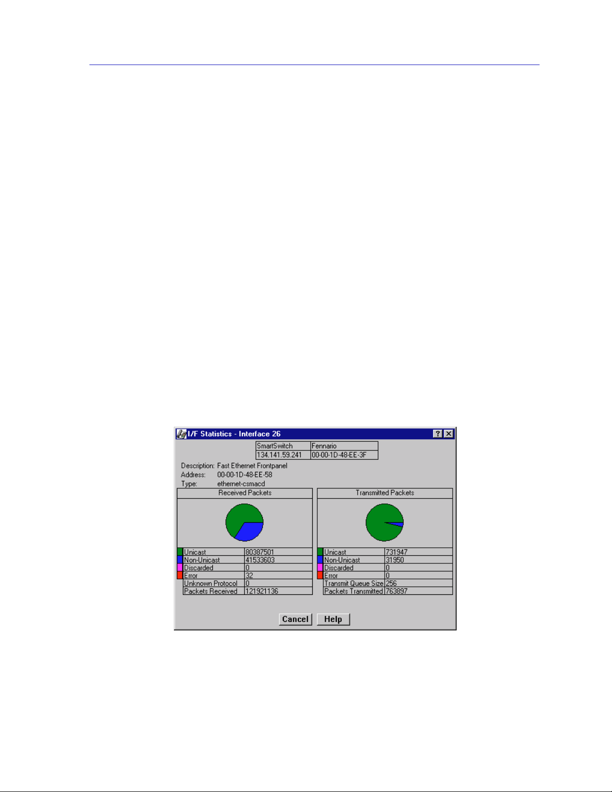
Out Octets The number of bytes transmitted by this interface,
When you select this option, a Bar Graph field will be added to the interface
display area; this field is only available when Load is the selected base unit.
Rate
The count for the selected statistic during the last poll interval. The available
parameters are the same as those provided for Raw Counts. Refer to the Raw
Counts section, above, for a complete description of each parameter.
Viewing Interface Detail
The Interface Statistics window (Figure 2-9) provides detailed MIB-II interface
statistical information — including counts for both transmit and receive packets,
and error and buffering information — for each individual port interface.
Color-coded pie charts also let you graphically view statistics for both received
and transmitted Unicast, Multicast, Discarded, and Error packets.
To open the Interface Statistics window:
The SmartSwitch 2000 Chassis View
expressed as a percentage of the theoretical maximum
load.
1. In the I/F Summary window, select the interface for which you’d like to view
more detailed statistics.
2. Click on Detail. The appropriate I/F Statistics window, Figure 2-9, opens.
Figure 2-9. Detail Interface Statistics
Viewing Chassis Information 2-21
Page 42

The SmartSwitch 2000 Chassis View
You can also access this information via the I/F Statistics option available on the
TIP
individual port menus; see Chapter 4, Statistics, for more information.
Three informational fields appear in the upper portion of the window:
Description
Displays the interface description for the currently selected interface.
Address
Displays the MAC (physical) address of the selected interface.
Type
Displays the interface type of the selected port.
The lower portion of the window provides the following transmit and receive
statistics. The first four statistics are also displayed in pie charts.
Unicast
Displays the number of packets transmitted to or received from this interface tha t
had a single, unique destination address. These statistics are displayed in the pie
chart, color-coded green.
Non-Unicast
Displays the number of packets transmitted to or received from this interface tha t
had a destination address that is recognized by more than one device on the
network segment. The multicast field includes a count of broadcast packets —
those that are recognized by all devices on a segment. These statistics are
displayed in the pie chart, color-coded dark blue.
Discarded
Displays the number of packets which were discarded even though they
contained no errors that would prevent transmission. Good packets are typically
discarded to free up buffer space when the network becomes very busy; if this is
occurring routinely, it usually m eans that network traffic is overwhelming the
device. To solve this problem, you may need to re-configure your bridging
parameters, or perhaps re-configure your network to add additional bridges or
switches.
These statistics are displayed in the pie chart, color-coded magenta.
Error
Displays the number of packets received or transmitted that contained errors.
These statistics are displayed in the pie chart, color-coded red.
2-22 Viewing Chassis Information
Page 43

The SmartSwitch 2000 Chassis View
Unknown Protocol
(Received only)
Displays the number of packets received which were discarded because they were
created under an unknown or unsupported protocol.
Packets Received
(Received only)
Displays the number of packets received by the selected interface.
Transmit Queue Size
(Transmit only)
Displays the number of packets currently queued for transmission from this
interface. The amount of device memory devoted to buffer space, and the traffic
level on the target network, determine how large the output packet queue can
grow before the SmartSwitch 2000 device wi ll begin to discard packets.
Packets Transmitted
(Transmit only)
Displays the number of packets transmitted by this interface.
Making Sense of Detail Statistics
The statistics available in this window can give you an idea of how an interface is
performing; by using the statistics in a few simple calculations, it’s also possible to
get a sense of an interface’s activity level:
To calculate the percentage of input errors:
NOTE
Received Errors /Packets Received
To calculate the percentage of output errors:
Transmitted Errors /Packets Transmitted
To calculate the total number of inbound and outbound discards:
Received Discards + Transmitted Discards
To calculate the percentage of inbound packets that were discarded:
Received Discards /Packets Received
To calculate the percentage of outbound packets that were discarded:
Transmit Discards /Packets Transmitted
The Interface Statistics window does not offer Disable or Test options. These options are
available in the Interface Group window, which can be accessed via the System Group
window (select S
ystem Group from the Device menu). See to th e Generic SNMP
User’s Guide for information on the System Group and Interface Group windows.
Viewing Chassis Information 2-23
Page 44

The SmartSwitch 2000 Chassis View
Using Device Find Source Address
When you select the Device Find Source Address option, the device’s 802.1d
Filtering database is searched for the specified MAC address. If it is found, the
Component field will display the value “Bridge” indicating that the address was
found on a bridging interface, and the Port Instance field will display the index
number assigned to the bridge port on which the address was located.
You may receive an error message stating “Can’t Display Source Address” if a Port
NOTE
Instance of “0” or “0.0” is reported. This value indicates that the MAC address is
communicating through the backplane instead of through a front panel interface.
To open the Device Find Source Address window:
1. Click on Device in the Chassis View menu bar.
2. Click on Device Find Source Address. The Device Find Source Address
window, as shown in Figure 2-10, opens.
Figure 2-10. Device Find Source Address Window
The Device Find Source Address window displays the following information:
Component
Displays the type of interface through which the specified MAC address is
communicating. This field will report Bridge.
2-24 Using Device Find Source Address
Page 45

NOTE
The SmartSwitch 2000 Chassis View
Port Instance
Displays the bridge port index number on which the specified MAC address was
found.
To use the Device Find Source Address window:
1. In the Address Mode field, select the format of the Source Address you wish
to find, either MAC or Canonical.
2. In the Enter Address text box, enter the Source Address you wish to find in
the appropriate XX-XX-XX-XX-XX-XX format.
If you enter the MAC format of a specified address, and then click on Canonical,
NetSight Element Manager will do the address conversion for you, from the Ethernet
hexadecimal format to the Token Ring Canonical format. The same is also true if you enter
the Canonical format of a speci fied address and then select MAC .
3. Click on the Find It! button. A “Processing Request” message opens in the
status bar at the bottom of the window.
If the specified MAC address is located, a list of the interface(s) through which the
given address is communicating displays in the lis t box. A status message at the
bottom of the window will display the number of interfaces through which the
given MAC address is communicating.
If the specified MAC address cannot be found, a “Source Address not found”
message displays.
If the MAC address is entered in an incorrect format, an “Invalid MAC Address.
NOTE
Enter Valid MAC Address” messag e displays. Enter the address in th e correct
XX-XX-XX-XX-XX-XX hexadecimal format.
Using Device Find Source Address on Ethernet MicroLAN Switches
When you select the Device Find Source Address option on an Ethernet
MicroLAN Switch, a search is made of both the Source Address Table (SAT) and
the 802.1d Filtering database to discover through which interface(s) a specified
source MAC address is communicating. If the MAC address is found, the
interface types “Bridge” and “Enet #” will display in the Component field with
their associated port index number displayed in the Port Instance field.
Using Device Find Source Address 2-25
Page 46

The SmartSwitch 2000 Chassis View
You may receive an error message stating “Can’t Display Source Address” if a Port
NOTE
Instance of “0” or “0.0” is reported while using the Device Find Source Address feature.
This value indicates that the MAC address is communicating through the backplane
instead of through a front panel interface.
To open the Device Find Source Address window:
1. Click on Device in the Chassis View menu bar.
2. Click to select Device Find Source Address. The Device Find Source
Address window, as shown in Figure 2-10, opens.
Figure 2-11. Dev ice Fin d Sou rce Address Window
The Device Find Source Address window displays the following information:
Component
Displays the type of interface through which the specified MAC address is
communicating. This field will display Bridge and Enet #, indicating that the
specified MAC address was found on a bridging interface and on an Ethernet
repeater channel.
Port Instance
Displays the port index number associated with the interface on which the
specified MAC address was found. For an address found on a bridging interface,
this field displays the bridge interface index number on which the specified MAC
address was found. For an address found on a repeater port, this field displays
the board (port group) number an d the port index number on which the specified
2-26 Using Device Find Source Address
Page 47

NOTE
The SmartSwitch 2000 Chassis View
MAC address was found. The board and port index numbers are separated by a
period; for example, a Port Instance of 1.2 refers to board (port group) 1 and port
number 2.
To use the Device Find Source Address window:
1. In the Address Mode field, select the format of the Source Address you wish
to find, either MAC or Canonical.
2. In the Enter Address text box, enter the Source Address you wish to find in
the appropriate XX-XX-XX-XX-XX-XX format.
If you enter the MAC format of a specified address, and then click on Canonical,
NetSight Element Manager will do the address conversion for you, from the Ethernet
hexadecimal format to the Token Ring Canonical format. The same is also true if you enter
the Canonical format of a speci fied address and then select MAC .
3. Click on the Find It! button. A “Processing Request” message displays in the
status bar at the bottom of the window.
If the specified MAC address is located, a list of the interface(s) through which the
given address is communicating displays in the lis t box. A status message at the
bottom of the window will display the number of interfaces through which the
given MAC address is communicating.
If the specified MAC address cannot be found, a “Source Address not found”
message displays.
Managing the Hub
In addition to the performance and configuration information described in the
preceding sections, the Chassis V iew also provides you with the tools you need to
configure your device and keep it operating properly. Hub management functions
include setting operating parameters for Ethernet, Fast Ethernet, Gigabit
Ethernet, and COM ports; redirecting traffic; viewing system resources;
performing 802.1Q VLAN configuration; setting broadcast suppression;
configuring port priority; setting device date and time; and enabling and
disabling ports.
Configuring Ports
The Configuration options available for FDDI, Ethernet, Fast Ethernet, Gigabit
Ethernet, and COM ports allow you to configure operating parameters specific to
each port type: for FDDI and standard Ethernet ports, you can set the Duplex
Mode; for Fast Ethernet ports on first generation devices, you can set a variety of
duplex mode and negotiation parameters; for Fast Ethernet and Gigabit Ethernet
ports on second generation devices you can set speed, duplex mode, and flow
Managing the Hub 2-27
Page 48
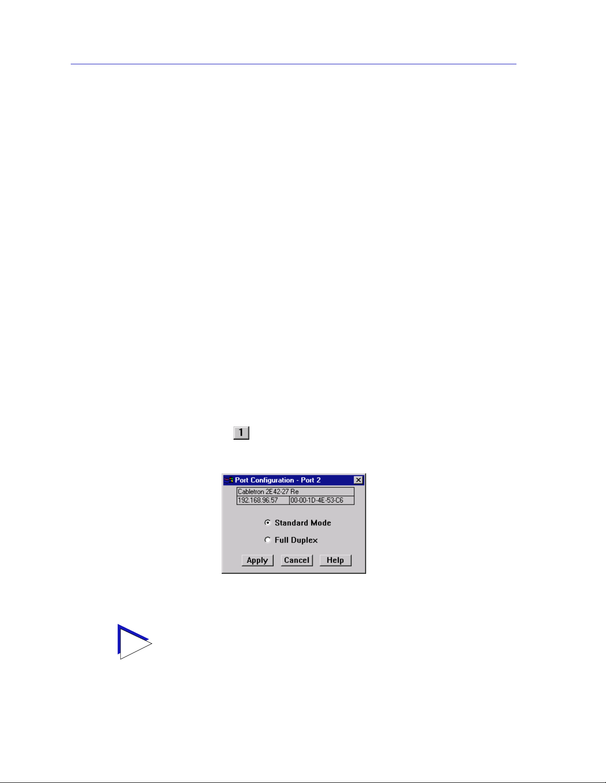
The SmartSwitch 2000 Chassis View
control parameters; and for COM ports, you can select the operation you wish the
port to perform, and set any associated speed parameters. FDDI, Ethernet, Fast
Ethernet, and Gigabit Ethernet Port Configuration windows are available from
the Chassis View Port menus (except on Ethernet MicroLAN Switches where they
are available from the Bridge Port menu); the COM Port option is available from
the Device menu.
Configuring Standard Ethernet and FDDI Ports
The Port Configuration window available for both standard Ethernet and FDDI
ports allows you to set an interface to either Standard or Full Duplex Mode. Full
Duplex mode effectively doubles the available wire speed by allowing the
interface to both receive and transmit simultaneously. This window will also
display the mode currently in effect on the selected interface.
To access the Port Configuration Window:
1. From the Chassis View, click to select the port you wish to configure; the Port
Menu will display.
2. Click on Configuration. The Port Configuration window, Figure 2- 12 , opens.
TIP
To access the Port Configuration wind ow on SmartSwitch 2000 Ethernet
MicroLAN Switches:
1. From the Chassis View , clic k on Device in the menu bar to access the Device
menu.
2. Click on Bridge Status. In the resulting window click on the Bridge Port
button (e.g., ) to access the Bridge Port menu.
3. Click on Configuration. The Port Configuration window, Figure 2- 12 , opens.
Figure 2- 12. The Port Con figuration Window
If you select the Configuration option available for a Fast Ethernet interface, an entirely
different window opens; see Configuring Fast Ethernet Ports on Firs t Generation
Devices, on page 2-29, or Configuring Ethernet Port s on Second Generation
Devices, on page 2-34, for information on config uring these ports.
2-28 Managing the Hub
Page 49

WARNING
The SmartSwitch 2000 Chassis View
For standard Ethernet interfaces, Full Duplex should only be enabled on an interface that
has a connection to a single destination address at the other end of the connection (i.e., it is
not a segment with an attached repeater cascading the connection to multiple destination
addresses).
Full Duplex mode disables the collision detection circuitry at the interface, so that both
Transmit and Receive wires can be used simultaneously. With a single destination address
at the other end of the connection (for example, if the connection was to a full duplex
interface on another switching device, or if a single file server was connected to the full
duplex switch port), this essentially doubles the available bandwidth from 10 Mbit/ sec to
20 Mbit/sec. Note that the interface at the other end of the connection must also have Full
Duplex enabled at the attached int erface.
Full Duplex mode must be disabled if the interface is communicating with multiple
destinations simultaneous ly (i.e., if a repeater is cascaded from the interface), sinc e
Ethernet relies on Collision Sense for proper operation.
Similarly, an FDDI Full Duplex connection must also only be run point-to-point between
two supporting FDDI interfaces (e.g., another HSIM-F6), since the dual bandwidth is
attained by running data on both primary and secondary paths simultaneously. Since
Full Duplex overrides standard FDDI protocol (and eliminates ring redundancy), it will
not operate in a “ring” configuration, but only as a point-to-point high speed data trunk
between hubs. Note that you must use Local Management to configure your HSIM-F6 for
Full Duplex operation prior to making physical connections. Refer to your Local
Management Guide for more information.
Use the options in this window to select the desired mode:
Standard Mode
In Standard Mode, an interface can only either transmit or receive at any given
time, and must wait for one activity to be completed before switching to the next
activity (receive or transmit). In this mode, standard wire speeds (10 Mbps for
Ethernet, 100 Mbps for FDDI) are avail able.
Full Duplex
In Full Duplex Mode, an interface can both receive and transmit packets at the
same time, effectively doubling the available wir e speed to 20 Mbps (for Ethernet)
or 200 Mbps (for FDDI).
Be sure to click on the Apply button to set your changes; note that the interface’s
current mode can be determined by the field selected in the window.
Configuring Fast Ethernet Ports on First Generation Devices
The SmartSwitch 2000 has two fr ont panel slots ( Ports 25 an d 26) f or Fast Ethern et
Interface Modules: the FE100-TX and FE100-FX. If you have any Fast Ethernet
Interface Modules installed in the front panel slots of your first generation
SmartSwitch 2000 device, the Fast Ethernet Configuration window available for
Managing the Hub 2-29
Page 50
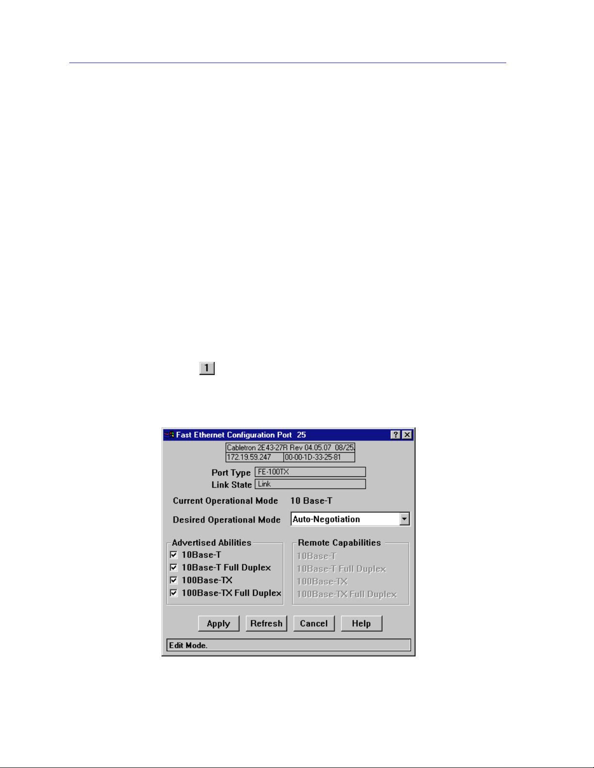
The SmartSwitch 2000 Chassis View
those ports allows you to both view and set that port’s available modes. All
100Base-TX Fast Ethernet ports can be configured to operate in either standard
Ethernet (10 Mbps) or Fast Ethernet (100 Mb ps) mode, and in each mode can be
configured to operate in Full Duplex, effectively doubling the available wire
speed (from 10 to 20 Mbps in standard Ethernet mode, o r fr om 10 0 to 200 Mbps in
Fast Ethernet mode); 100Base-FX (fiber) ports ca n be configur ed to oper ate in their
standard 100 Mbps mode, or in full duplex mode. This window also displays the
mode currently in effect on the selected interface, and provides some information
(where it is available) about the interface’s link partner.
To access the Fast Ethernet Configuration Window:
1. From the Chassis View, click to select the Fast Ethernet port you wish to
configure; the Port Menu will display.
2. Click on Configuration. The Fast Ethernet Configuration window,
Figure 2-13, opens.
To access the Fast Ethernet Configuration window on SmartSwitch 2000 Ethernet
MicroLAN Switches:
1. From the Chassis View , clic k on Device in the menu bar to access the Device
menu.
2. Click Bridge Status. In the resulting window click on the Bridge Port button
(e.g., ) to access the Bridge Port menu.
3. Click Configuration. The Fast Ethernet Configuration window, Figure 2-13,
opens.
Figure 2-13. The Fast Ethernet Port Configuration Window
2-30 Managing the Hub
Page 51

NOTE
TIP
The SmartSwitch 2000 Chassis View
Auto-Negotiation is not supported by the FE-100FX Fast Ethernet port interface module.
If you launch the window for a port module slot which has no FE module installed, the
Port Type will display as Unknown, the Link State will display No Link, and the rest of
the fields will be blank and/or grayed out.
If you select the Configuration option available for a standard Ethernet or FDDI interface,
or for an Ethernet port on a second generation device, an entirely different window opens;
see Configuring Standard Ethernet and FDDI Ports, on page 2-28, or Configuring
Ethernet Ports on Second Generation Dev ices, page 2-34, for information on
configuring these ports.
From this window you can manually set the operational mode of the port, or —
for 100Base-TX interfaces — set the port to auto negotiation so that the
appropriate operational mode can be determined automatically. The mode you
set will determine the speed of the port and whether it uses Full Duplex or
Standard Mode bridging.
The following information about the selected Fast Ethernet port is displayed:
Port Type
Displays the port’s type: FE-100TX (for the FE-100TX Fast Ethernet port module),
FE-100FX (for the FE-100FX Fast Ethernet port module), or Unknown (for a port
slot with no module installed).
Link State
Displays the current connection status of the selected port: Link or No Link.
Current Operational Mode
Indicates which of the available operational modes is curr ently in ef fect: 10Base-T,
10Base-T Full Duplex, 100Base-TX, 100Base-TX Full Duplex, 100Base-FX, or
100Base-FX Full Duplex. If the port is still initializing, not linked, or if there is no
port module installed in the slot, this field will remain blank.
Desired Operational Mode
Displays the operational mode that you have selected for this port, and allows
you to change that selection. The following op erational modes are available for
each port:
100Base-TX Auto Negotiation, 10Base-T, 10BASE-T Full Duplex,
100Base-TX, and 100Base-TX Full Duplex.
100Base-FX 100Base-FX and 100Base-FX Full Duplex
Managing the Hub 2-31
Page 52

The SmartSwitch 2000 Chassis View
If you choose to select a specific mode of operation (rather than auto-negotiation), you
!
CAUTION
should be sure that the link par tner supports the same mode. Otherwise, no link wi ll be
achieved.
If you select a Full Du plex mod e and t he link part ner supp orts th e same w ir e spee d but not
Full Duplex, a link will be achieved, but it will be unstable and will behave erratically.
If you select Auto-Negotiation, the local node will try to match the mode of the link
partner, even if the link partner is not set to auto-negotiate, and even if the local node
must use a mode which it is not currently advertising .
If Auto Negotiation is the selected mode, the Current Operational Mode field
will indicate which mode was selected by the link partners. See Setting the
Desired Operational Mode, on page 2-33, for more information.
Advertised Abilities
For 100Base-TX ports which have been configured to operate in Auto Negotiation
mode, this field allows you to select which of the operational modes available to
the port can be selected by the negotiating link partners. During Auto
Negotiation, each of the link partners will advertise all selected modes in
descending bandwidth order: 100Base-TX Full Duplex, 100Ba se-TX, 10Base-T Full
Duplex, and 10Base-T. Of the selected abilities, the highest mode mutually
available will automatically be used. If there is no mode mutually advertised, no
link will be achieved.
NOTE
If you have selected a specific operational mode for your 100Base-TX port, the
Advertised Abilities do not apply; the sel ect ed Advertised Abilities also do not
restrict the local node’s ability to set up a link with a partner who is not currently
Auto-Negotiating.
Auto-Negotiation is not currently supported for 100Base-FX ports.
Remote Capabilities
When the local node is set to Auto-Negotiation, this field will display the
advertised abilities of the remote link — even if the remote link is not currently set
to auto-negotiate. Possible values for this field are:
• 100Base-TX Full Duplex
• 100Base-TX
• 10Base-T Full Duplex
• 10Base-T
2-32 Managing the Hub
Page 53

TIP
The SmartSwitch 2000 Chassis View
• Link Partner does not support auto negotiation — auto negotiation is either
not supported by or is not currently selected on the remote port.
• Unknown — the link partner’s capabilities could not be determined.
When the local node is not set to Auto-Negotiation, this field will be grayed out,
even if the link partner is set to Auto-Negotiation and is advertising abilities.
Setting the Desired Operational Mode
For any 100Base-TX port, you can specifically choose any one of the four available
operational modes, or you can select Auto-Negotiation mode, which allows the
port to negotiate with its link partner to find the highest mutually available
bandwidth. If you select Auto Negotiation mode, you must also choose which of
the port’s bandwidth capabilities you wish to advertise to the link partner.
If you select Auto-Negotiation at both ends of a link, be sure at least one
mutually-advertised operational mode is available.
For a 100Base-FX port, the selection process is somewhat simpler; Auto
Negotiation for these ports is not supported at this time, so you need only choose
between 100Base-FX standard mode and 100Base-FX Full Duplex. However, you
must still be sure that both link partners are set to the same operational mode, or
the link will be unstable.
To set your desired operational mode:
1. Click on the Desired Operational Mode combo box to display the menu of
available options; click to select the operational mode you wish to set.
For 100Base-TX ports, the available options are:
10Base-T — 10 Mbps connection, Standard Mode
10Base-T Full Duplex — 10 Mbps connection, Duplex Mode
100Base-TX — 100 Mbps connection, Standard Mode
100Base-TX Full Duplex — 100 Mbps connection, Duplex Mode
Auto Negotiation — the operational mode will be dynamically set based on
the modes selected in the Advertised Abilities field (where both link partners
are auto-negotiating) and the speeds and modes supported by the attached
device.
For 100Base-FX ports, options are:
100Base-FX — 100 Mbps connection, Standard Mode
100Base-FX Full Duplex — 100 Mbps connection, Duplex Mode
Managing the Hub 2-33
Page 54

The SmartSwitch 2000 Chassis View
2. If you have selected Auto Negotiation (for 100Base-TX ports only), use the
Advertised Abilities field to select the operational capabilities you wish to
advertise to the port’s link partner. If both link partners will be
auto-negotiating, be sure there is at least one mutually-advertised operational
mode, or no link will be achieved.
The selected Advertised Abilities only come into play when both link partners are
TIP
auto-negotiating; if only one link partner is set to auto-negotiate, that node will establish a
link at whatever mode its partner is set to, even if that mode is not currently being
advertised.
3. Click Apply to save your changes. Click Refresh to display the new settings.
It may take a few minutes for mode changes to be completely initialized,
particularly if the link partners must negotiate or re-negotiate the mode; you
may need to refresh the window a few times before current operational data is
displayed.
Configuring Ethernet Ports on Second Generation Devices
The Ethernet Configuration window available for Fast Ethernet and Gigabit
Ethernet ports on second generation devices (e.g., 2H252-25R and 2H258-17R)
allows you to both view and set those ports’ available speed, modes, and flow
control. All second generation devices support the ctEthernetParameters M IB. All
Ethernet ports that return at least one instance for a query of the
ctEtherSupportedDuplex OID will use the Ethernet Configuration window as
shown in Figure 2-14.
All 100Base-TX Fast Ethernet ports can be configured to operate in either standard
Ethernet (10 Mbps) or Fast Ethernet (100 Mb ps) mode, and each mode can be
configured to operate in Full Duplex effectively doubling the available wir e speed
(from 10 to 20 Mbps in standard Ethernet mode, or from 100 to 200 Mbps in Fast
Ethernet mode). 100Base-FX (fiber) ports can be configured to operate in their
standard 100 Mbps mode, or in Full Duplex mode. 1000Base-SX/LX/CX Gigabit
Ethernet ports are always configured to operate in 1000 Mbps, Full Duplex mode.
This window displays the mode currently in effect on the selected interface, and
provides some information (where it is available) about the interface’s link
partner.
To access the Ethern et Configuration Window:
1. From the Chassis View, click to select the port you wish to configure; the Port
Menu will display.
2. Click on Configuration. The Ether net Confi gu ration window, Figure 2-13,
opens.
2-34 Managing the Hub
Page 55
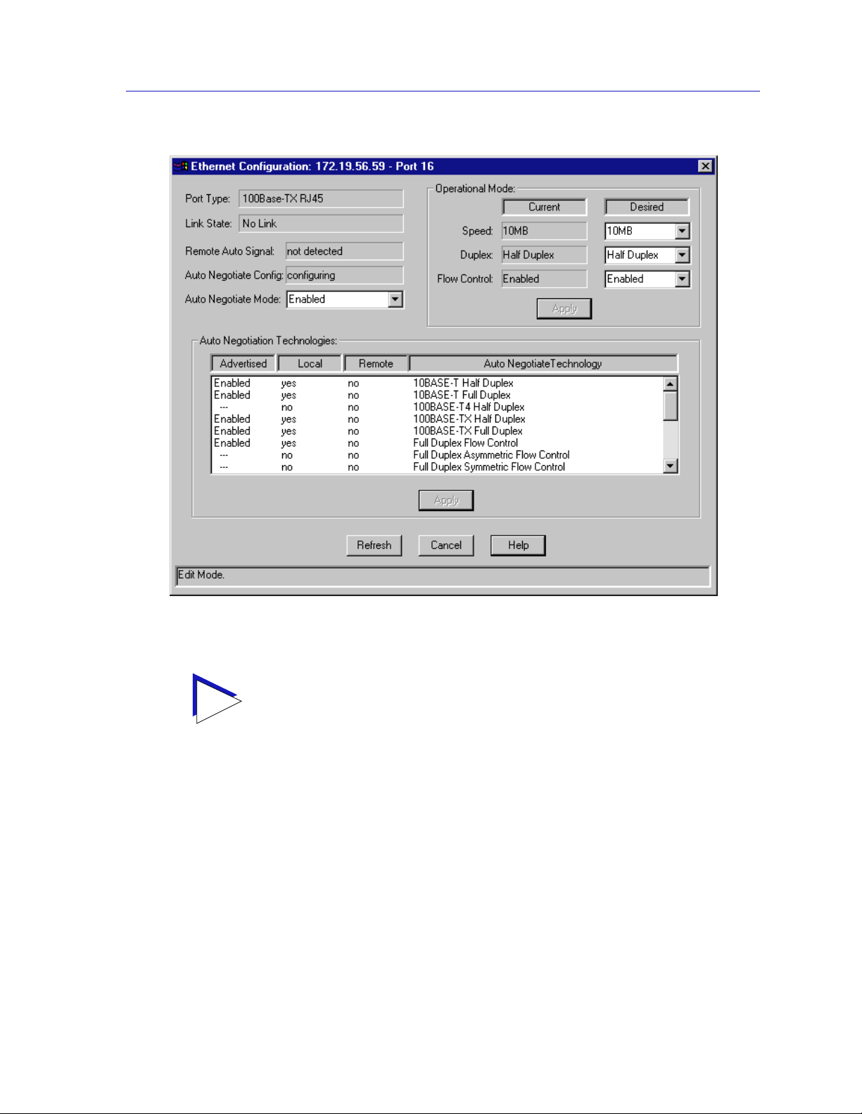
The SmartSwitch 2000 Chassis View
TIP
Figure 2-14. The Ethernet Configuration Window
If you select the Configuration option available for a standard Ethernet or FDDI interface
or for a Fast Ethernet port on a first generation device, an entirely different window opens;
see Configuring Standard Ethernet and FDDI Ports, page 2-28, or Configuring Fast
Ethernet Ports on First Generati on Devices, page 2-29, for information on
configuring these ports.
From this window you can manually set the operational mode of the port, or —
for 100Base-TX and 1000Base-SX/LX/CX interfaces — set the port to Auto
Negotiate so that the appropriate operational mode can be determined
automatically. The mode you set will determine the port’s speed, duplex mode,
and flow control.
The window displays the following information about the selected Ethernet port:
Port Type
Displays the port’s type: 100Base-TX RJ-45or RJ71 (fo r built-in Fast Ethernet ports
and the FE-100TX Fast Ethernet port module), 100Base-FX MMF SC Connector
Managing the Hub 2-35
Page 56

The SmartSwitch 2000 Chassis View
(for the FE-100FX Fast Ethernet port module), 1000Base-SX/LX/CX (for the
VHSIM-G6 Gigabit Ethernet port module), or Unknown (for a port slot with no
module installed).
Link State
Displays the current connection status of the selected port: Link or No Link.
Remote Auto Signal
Indicates whether the operating mode at the remote end of the link is set to Auto
Negotiate.
Auto Negotiate Config
Indicates whether Auto Negotiate signalling is in progress or has completed.
Possible values for this field are: configuring, complete, disabled, parallel detect
failed, or other.
Auto Negotiate Mode
Use this field to enable or disable Auto Negotiate for the port. If Auto Negotiate is
disabled, the port will use the speed, duplex mode, and flow control settings
specified in the Operational Mode fields. Note that 100-BaseFX ports do not
support Auto Negotiation; they must use the control settings specified in the
Operational Mode fields.
!
CAUTION
Operational Mode Fields
If the port is not set to Auto Negotiate then the settings in the Operational Mode
fields are used.
If you choose to select a specific mode of operation (rather than auto negotiation), you
should be sure that the link par tner supports the same mode. Otherwise, no link wi ll be
achieved.
For example, if you select Full Duplex mode and the li nk partner supports the sam e wire
speed but not Full Duplex, a link will be achieved, but it will be unstable and will behave
erratically.
If you select Auto-Negotiation, the local node will try to match the mode of the link
partner, even if the link partner is not set to auto-negotiate, and even if the local node
must use a mode which it is not currently advertising .
The Current Operational Mode settings indicate which of the available
operational modes is currently in effect. If Auto Negotiate is the selected mode,
the Current Operational Mode fields will indicate which mode was selected by
the link partner.
The Desired Operational Mode settings display the operational mode that is
currently selected for this port, and allows you to change the selection.
2-36 Managing the Hub
Page 57

The SmartSwitch 2000 Chassis View
The following operational modes can be specified:
Speed
This field specifies a port speed of 10MB, 100MB, or 1000MB.
Duplex
This field specifies Half Duplex or Full Duplex mode for the port.
Flow Control
Flow control allows Ethernet devices to notify attached devices that congestion is
occurring and that the sending device should stop transmitting until the
congestion can be cleared. There are two commonly used methods of flow control:
Frame-based (operates on Full Duplex links) and Backpressure (operates on Half
Duplex links).
Ports set to Full Duplex mode have frame-based flow control, using pause
control frames. Frame-based flow control options are:
Symmetric The port is able to both receive and transmit pause control
frames.
Asymmetric RX This option appears only for Gigabit Ethernet ports. The port
will receive pause control frames, but will not transmit its own.
Asymmetric TX This option appears only for Gigabit Ethernet ports. The port is
capable of sending pause control frames, but will not
acknowledge received pause co ntrol frames.
Disabled Disables flow control on the port.
Auto Negotiat e Ports configured to operate in auto negotiation mode will only
use pause control frames if the negotiation process determines
that the link partner supports them. Both ends of the link must
support auto negotiation and a common mode of operation.
Ports set to Half Duplex mode use Backpressure flow control. Backpressure flow
control simply asserts the carrier sense signal out the port causing the device
transmitting to detect a collision, stop trans mitting data, and send the jam signal.
Backpressure flow control options are enabled or disabled.
Setting the Desired Operational Mode
For any 100Base-TX port, you can configure operational modes, or yo u can select
Auto Negotiate mode, which allows the port to negotiate with its link partner to
find the highest mutually available bandwidth a nd flow control. If you select
Auto Negotiate mode, you must also choose which of the port’s bandwidth and
flow control capabilities you wish to advertise to the link partner (refer to Auto
Negotiation Technologies , page 2-38).
Managing the Hub 2-37
Page 58

The SmartSwitch 2000 Chassis View
100Base-FX ports do not support auto negotiation for bandwidth or flow control
capability, so you must choose between 100Base-FX Half Duplex and 100Base-FX
Full Duplex mode, and set the flow control option. However, you must still be
sure that both link partners are set to the same operational mode, or the link will
be unstable.
For 1000Base-SX/LX/CX ports the speed and duplex modes are always
configured at 1000MB Full Duplex. However, you can select Auto Negotiate
mode, which allows the port to negotiate with its link partner to find the highest
mutually available bandwidt h and flow control. If you select Auto Negotiate
mode, you must also choose which of the port’s bandwidth and flow control
capabilities you wish to advertise to the link partner (refer to Auto Negotiation
Technologies, page 2-38).
To set your desired operational mode:
1. Click on the Speed, Duplex, or Flow Control list box to display the menu of
available options; click to select the operational mode you wish to set.
If the port you are configuring does not support Flow Control, the Current Mode field will
NOTE
display “not supported” and the Desired Mode list box will be disabled.
TIP
2. Click on the Apply button to save your changes.
Auto Negotiation Technologies
For ports which have been configured to operate in Auto Negotiate mode, this list
box allows you to select which of the operational modes available to the port will
be advertised to the negotiating link partner.
During Auto Negotiation, each of the link partners will advertise all selected
modes. Of the selected modes, the highest mode mutually available will
automatically be used. If there is no mode mutually advertised, no link wil l be
achieved.
If you select Auto-Negotiation at both ends of a link, be sure at least one
mutually-advertised operational mode is available.
If you have man ua l ly c on f i g ured specific operation al modes for your 100Base-TX
port or if you are configuring a 100Base-FX port, the Auto Negotiation
Technologies list box does not apply.
2-38 Managing the Hub
Page 59

The SmartSwitch 2000 Chassis View
The Auto Negotiation Technologies list box has the following column heading s:
Advertised
This column specifies whether the operational mode listed in the far right column
of the list box will be advertised to the link partner. Only those operational modes
supported by the local port (those with a “yes” listed in the Local column) can be
advertised. Valid values are Enabled (the mode is supported and will be
advertised), Disabled (the mode is supported but will not be advertised), and
“---” (the mode is not supported).
Local
Indicates whether the operational mode listed in the far right column of the list
box is supported by the local port.
Remote
Indicates whether the operational mode listed in the far right column of the list
box is supported by the remote port.
Auto Negotiate Technology
This column lists possible opera tional modes.
Setting Advertised Abilities for Auto Negotiation
You can determine which operational mode supported by the local port will be
advertised to the negotiating link partner. Of the advertised modes, the highest
mode mutually available will automatically be used.
To advertise an operational mode:
1. In the list box, click on the operational mode of choice.
If the Advertised column had a value of Enabled, it will change to Disabled; a
value of Disabled will change to Enabled. If the Advertised column has a value
of “---”, then the value is not changed.
2. Click Apply to save your changes. Click Refresh button to display the new
settings. It may take a few minutes for mode changes to be completely
initialized, particularly if the link partners must negotiate or re-negotiate the
mode; you may need to refresh the window a few times before current
operational data is displayed.
Configuring the COM Port
You can use the COM Port Configuration window (Figure 2-15) to specify the
functions that will be performed by the RS232 COM port on the SmartSwitch 2000
front panel.
1. Click on D
evice in the Chassis View menu bar to display the Device menu.
Managing the Hub 2-39
Page 60

The SmartSwitch 2000 Chassis View
2. Click on Com Port Configuration, and then select Port 1, and release. The
Com Port Configuration window, Figure 2-15, opens.
Figure 2- 15. The Com Port Configuration Window
You can use the Com Port Configuration window to set the following operating
parameters:
Com Port Admin
Use this field to administratively enable or disable the COM port.
Com Port Function
Use this field to select the function for which you wish to use the COM port:
LM Local Management: select this option if you wish to connect a
terminal to the selected COM port from which to run Local
Management.
UPS Select this option if you wish to connect an uninterruptable
power supply (UPS) to the selected COM Port. Note that if you
select this option, an additional option — UPS — displays on the
Device menu; use the resulting window to configure specific UPS
settings.
SLIP Select this option to use the selected COM port as a SLIP
connection for out-of-band SNMP management via direct
connection to a serial port on your network management
workstation. Note that when you configure the port as a SLIP
connection, you must select the desired baud rate in the Speed
Selection field described below.
PPP Select this option to use the selected COM port as a PPP
connection for out-of-band SNMP management via direct
connection to a serial port on your network management
2-40 Managing the Hub
Page 61

TIP
The SmartSwitch 2000 Chassis View
workstation. Note that when you configure the port as a PPP
connection, you must select the desired baud rate in the Speed
Selection field described below.
Speed Selection
If you have configured the selected port as a SLIP or PPP connection, you must
select the appropriate baud rate: 2400, 4800, 9600, or 19,200. Note that this field
will default to Auto-Baud and become unselectable when the Com Port Function
is set to LM or UPS.
If the COM port you wish to configure is currently set to LM or UPS, the Speed Selection
field will be unavailable until the Com Port Function is set to SLIP or PPP and that
change is applied. Once available, the Speed Selection field will default to the last known
speed setting; use the down arrow to change this setting if necessary, then click the Apply
button again to complete the configuration.
To change the configuration of the selected COM port:
1. Click on to the right of each field and select the desired setting.
2. Click on the Apply button to save your changes.
Using an Uninterruptable Power Supply (UPS)
Y our Sm artSwitch 2000 supports the use of a UPS (un interruptable power supply)
through the COM 1 port. (For more information on the use of a UPS with the
SmartSwitch 2000, consult the Sma rtSwitch 2000 Installation Ma nua l that was
included when you purchased the unit.) You can view or change the status of the
UPS connected to your SmartSwitch 2000 at the UPS window.
Please note that the UPS menu option will only be available when you have set
the Com Port Function to UPS in the COM Port Configuration, and the UPS
window will only be active if you currently have a UPS attached to your
SmartSwitch 2000 through the appropriate port, and you have correctly set the
Set UPS ID field.
Do not set the Set UPS ID field unless you have a UPS attached to the
!
CAUTION
SmartSwitch 2000, or you will disrupt your use of NetSight Element Manager.
Accessing the UPS Window
At the UPS window, you can configure the UPS ID model type for the
uninterruptable power supply you have attached to the COM port on your
SmartSwitch 2000.
Managing the Hub 2-41
Page 62
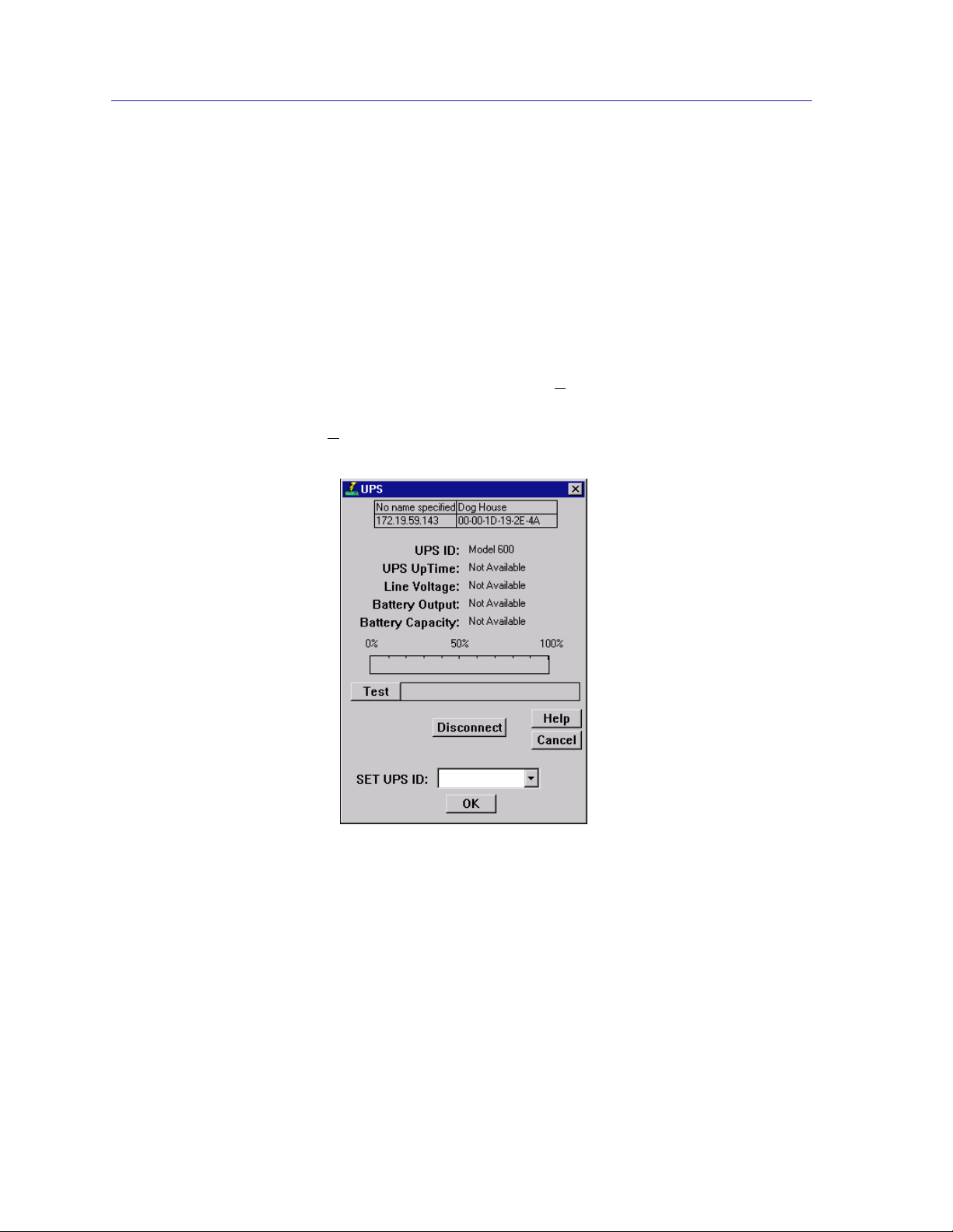
The SmartSwitch 2000 Chassis View
You can also view information concerning the UPS connected to your
SmartSwitch 2000 including:
• The amount of time that your UPS has been running since the last start-up
• The line voltage and battery output
• The actual battery capacity of the UPS (dynamic bar graph)
You can also use a button at the bottom of the window to disconnect your UPS, or
you can use the Test option to initiate a self test of the un it.
To access the UPS window:
1. From the Chassis View window, click on D
Device menu.
2. Select U
PS. The UPS window, Figure 2-16, opens.
evice in the menu bar to access the
Figure 2-16. The UPS Window
UPS ID
Displays the manufacturer and model typecode of the UPS attached to the COM
port of the SmartSwitch 2000. You must assign this typecode for the UPS window
to be active. (See Setting the U PS ID , on page 2-43, for instructions for setting the
typecode for your UPS.) The valid typecodes are:
• Model 370
• Model 400
• Model 600
• Model 900
2-42 Managing the Hub
Page 63

The SmartSwitch 2000 Chassis View
• Model 1250
• Model 2000
• Matrix 3000
• Matrix 5000
•SU 700
• SU 1400
• SU 2000XL
•Other
UPS Uptime
Displays the number of hours that the UPS has been operating since the last time
it was started up.
Line Voltage
Displays the voltage coming through the line attached to the SmartS witch 2000.
Battery Output
Displays the amount of battery output voltage.
Battery Capacity
Displays the percentage of remaining battery capacity (100% indicates a fully
charged battery).
Test Results
Displays the result of the last self-test performed by the UPS. The possible test
results are:
Unit OK The UPS unit is in working order.
Unit Failed The UPS unit has failed the self-test. Check the
unit for damage or consult your UPS User’s
Manual.
Bad Battery The UPS unit battery is bad.
No recent test No UPS self-test has been performed in the last
five minutes.
Unit in test... The UPS is currently in test mode.
Please standby
Setting the UPS ID
You need to set the UPS ID typecode that indicates the manufacturer and model
of the UPS.
Managing the Hub 2-43
Page 64

The SmartSwitch 2000 Chassis View
To set the UPS ID:
1. Click on next to the SET UPS ID text box. A Model number menu
displays. Scroll to highlight the appropriate UPS ID. (Consult the manual that
was included when you purchased your UPS for the correct Model ID
number.)
2. Click OK. The UPS ID you have chosen displays in the text box, and the UPS
window will be active.
If your UPS unit does not function after you have set this ID, check the manual
you received with the UPS to ensure that you have chosen the correct UPS ID. If
you need to change the ID, follow the directions given above.
Using the Test Option
You can use the test option to activate a self-test cycle for your unit. This self-test
will check the viability of your unit and its battery.
To activate the test:
1. Click on the Test button. The unit will begin its self-test. The results of the test
display in the Test Result text box next to the Test button.
Using the Disconnect Option
You can disc onnect the UPS attached to your SmartSwitch 2000 through its com
port, as follows:
1. Click on the Disconnect button near the bottom of the UPS window. Your
UPS will now be disconnected.
To reconnect, click OK, or close, then re-open the UPS window.
Redirecting Traffic on the SmartSwitch 2000
The Port Redirect window (Figure 2-17) allows you to redirect traffic from one or
more interfaces directly to another interface — essentially mirroring the traffic at
the “redirect” interface. This feature is useful in that it allows you to use an
external analyzer on the “redirect” port to analyze data, without disturbing the
normal switching operations at the original source ports. The Port Redirect
window displays the interface remap table and allows you to add new entries to
and delete existing entries from this table. When you set a source port to redirect
to a destination port, the destination port will transmit out all packets received or
transmitted on the source port.
2-44 Managing the Hub
Page 65

To access the Port Redirect window:
The SmartSwitch 2000 Chassis View
1. Click on D
2. Click Port R
evice in the Chassis View menu bar to display the Device menu.
edirector. The Port Redirect window, Figure 2-17, opens.
Figure 2-17 . The Port Redirect Window
The current port mappings will be listed in this window. You may add or delete
entries from this window.
To add an entry:
1. Next to the Source Port display box click on and select the desired source
port (Port X) from the drop down list.
2. Next to the Destination Port display box click on and select the desired
destination port (Port X) from the drop down list.
3. Click Add to add the redirect pair you have just configured to the list.
The new entry will now be displayed in the Current Active Entries list in this
window and the port traffic will begin to be redirected.
Managing the Hub 2-45
Page 66

The SmartSwitch 2000 Chassis View
To delete an entry:
1. Highlight the entry line in the current active entries list that you wish to delete.
2. Click Delete to remove the redirect pair you have highlighted from the current
active entries list.
The entry will be deleted from the current active entries list and the traffic from
the source port will not be redirected to the destination port any longer.
Priority Configuration
The SmartSwitch 2000 devices support priority packet forwarding. Priority
packet forwarding lets you designate certain packets to be of higher importance
than others, thereby allowing for the forwarding of these packets before packets
of lower priority. This functionality is essential for time-critical application s —
such as real-time video — on shared networks.
The Priority Configuration me nu option will only appear in the Device menu for
NOTE
devices that respond to any of NetSight Element Manager’s queries to the following
OIDs: ctPriorityExtPortStatu s, ctPriorityExtMaxNumMACEntries, or
ctPriorityExtNumPktTypeEntries. If your device’s firmware does not respond to these
queries, contact the Global Technical Assistance Center for upgrade information.
Frame priority is enabled by the “tagging” of MAC frames so that they are given a
priority designation when they are forwarded by the SmartSwitch 2000 device —
which is a tag-aware switch (i.e., one that adheres to the IEEE P802.1p and IEEE
P802.1q Draft Standards). Tagging a frame is accomplished by adding a Tag
Header to a frame immediately f ollowing its original Destination and Source
MAC address fields (and any r outing fields, if pre sent), and then r ecomputing the
Frame Check Sequence (FCS) appropriately. On receiving such a frame, a
tag-aware switch will read the priority from the tagged portion of the frame,
remove the Tag Header, recompute the FCS, and then direct it to its appropriate
transmission queue.
There are eight priority levels — indicated 0 through 7— available to designate
user priority. Frames tagged with a 0 represent the lowest priority level (or
normal) traffic, and frames tagged with a 7 indicate the highest priority level
traffic.
The SmartSwitch 2000 itself supports two transmission queues: one that is for 0 or
normal priority traffic (or any non-tagged traffic), and a second queue that is
reserved for frames that have been tagged with a priority level of 1 or higher. On
receiving any priority-tagged frames, the SmartSwitch 2000 will forward them
out of the high priority queue before forwarding any frames in the normal
priority queue. However, the SmartSwitch 2000 will tag outgoing frames with the
full range of eight priority levels, so that upon reception, a device that supports
the entire range of priority queuing will forward the frame appropriately.
2-46 Managing the Hub
Page 67

The SmartSwitch 2000 Chassis View
You can use NetSight Element Manager to configure the criteria that determine
the priority in which frames will be queued for transmission by your SmartSwitch
2000. Several different criteria can be used to determine a frame’s transmission
queue order:
• The device and port at which the frame was received.
• The destination and/or source MAC address associated with the frame.
• A combination of destination and/or source MAC address and the frame’s
protocol type.
• The frame’s protocol type.
When you configure the transmission queue for a specific frame, an entry is made
in one of three priority tables maintained by the SmartSwitch 2000 device. These
tables are used to determine which transmit queue to use — normal priority or
high priority — when forwarding frames.
•The ctPriorityExtPortTable maintains priority entries based on a frame’s receive
port.
•The ctPriorityExtMACT able maintains priority entries based on a frame’s
MAC-layer information.
•The ctPriorityExtPktTypeTable maintains priority entries based on the frame’s
protocol type.
The following sections discuss how to use the Port Priority Configuration
window, the MAC Based Priority Configuration window, and the Frame Priority
Configuration window to make entries in these transmit priority tables.
Configuring Priority Queuing Based on Receive Port
You can use the Port Priority Configuration window, Figure 2-18, to determine
packet queuing based solely upon the port at which the packet was received. This
allows you to ensure that a connected user or LAN segment will have priority
when frames that were received on that port are queued for transmission.
Managing the Hub 2-47
Page 68

The SmartSwitch 2000 Chassis View
Highlight a port, then use the
drop-down list box to select a
priority (Normal–7).
Click Apply to set the priority
at the device. Any priority of 1
or higher will allow packets
received at the chosen port to
be forwarded from the higher
priority transmission queue.
Figure 2-1 8. The Port Priority Configuration Window
NOTES
In the event that an incoming packet received on a designated port already has a priority
associated with it, you can use the ctPriorityExtPortFwdInboundPriority OID to
determine whether the incoming priority should remain intact, or be replaced with the
priority that you have set for the receiving port.
Use the MIB T ools utility suite to set the ctPriorityExtPortFwdInboundPriority OID
to 1 (for the appropriate port instance) if you want the incoming packet to retain its
originally set priority when received by the port; set the OID to 2 if you want the packet to
take the default priority set for the receiving port. Refer to the Tools Guide for
information on using the MIB Tools suite.
To access the Port Priority Configuration window:
1. Click on D
2. Click on P
The Port Priority Configuratio n window opens.
The Port Priority Configuration window displays the contents of the
ctPriorityExtPortTable. It has a list box that displays the front panel interfaces
supported by the SmartSwitch 2000 device, along with the slot number occupied
by the module (for the SmartSwitch 2000, the slot number will always be 1), and
any transmit priority that has been assigned to those interfaces.
To assign a transmit priority to a port:
evice to access the Device menu.
riority Configuration, and then select Port Based from the menu.
1. Click to highlight the port interface of interest in the Po rt # column. Each
IfIndex
interface is identified by its MIBII
.
2-48 Managing the Hub
Page 69

The SmartSwitch 2000 Chassis View
2. Click on the Transmit Priority drop-down list box, and scroll to select the
desired priority level (Normal–7) for forwarding packets received on the
selected port.
Since the SmartSwitch 2000 device has two transmit queues, a priority of Normal will
NOTE
Configuring Priority Queuing Based on MAC-layer Information
cause packets received on that port to be forwarded through the lower priority queue, and
any priority of 1 through 7 will cause the packets to be forwarded through the higher
priority queue. However , other tag-aware switches may use the full range of eight priority
queues — so the pri ority th at you as sig n may h ave be aring on how the frame i s fo rwarded
when it is received by another device.
3. Click Apply. The defined priority displays next to the port in the Transmit
Priority column.
You can use the MAC Based Priority Configuration window, Figure 2-19, to
determine packet queuing based upon the packet’s Source and/or Destination
MAC address, as well as the packet’s frame T ype. These priority entries, based on
the frame’s MAC-layer information, are maintained in the ctPriorityExtMACTable.
You can create up to 1024 priority entries for queuing frames based upon on
MAC-layer information.
Click Add to enter a
Select whether you want
the address type to be
destination, source, or
either type.
Determine whether to apply the
priority to all frames with the given
address and SA/DA type, or only
to frames of a specific type.
MAC Address to which
you want to assign a
higher priority
transmission queue.
Finally, select a priority level,
and click Apply.
Figure 2-19 . The MAC Based Priority Configuration Window
Managing the Hub 2-49
Page 70

The SmartSwitch 2000 Chassis View
To access the MAC Based Priority Configuration window:
1. Click on D
2. Click on P
The MAC Based Priority Configuration window opens.
The MAC Based Priority Configuration window contains the following
information:
Current Priority Entries
The Current Priority Entries list box displays any MAC-based priority entries that
have been configured for the SmartSwitch 2000 device. It has four columns:
• MAC Address, which identifies the physical address for which a frame
transmit priority entry has been configured.
• Address Type, which identifies whether the address of interest is in the sour ce
or destination field, or in both fields, of the frame.
• Frame Type, which indicates whether all frames with the given address will
have a transmit priority, or whether a specified frame Type will be used in
combination with the address.
• Priority, which displays the current transmit priority assigned to the entry.
Below the Current Priority Entries list box, several text fields and command
buttons allow you to configure or edit MAC-based priority entries:
evice to access the Device menu.
riority Configuration, and then select MAC Based from the menu.
MAC Address
This text field allows you to enter a new MAC address that will h ave a transmit
priority associated with it.
Address Type
This drop-down list box allows you to select whether the given MAC address
must be in the source address portion of the frame (SA), the destination address
portion (DA), or in either portion (SA/DA).
Frame Type
This radio button/text box combinat ion allows you to choose whether All frame
Types wit h the given address will be given priority, or whether frames of a
Specific type (as defined in the associated text box) will be given priority.
Priority
Priority, which indicates the transmit priority level assigned to the configured
entry.
2-50 Managing the Hub
Page 71

The SmartSwitch 2000 Chassis View
To assign a transmit priority based on MAC-layer information:
1. Click on the Add button. The entry fields will be activated.
2. Click in the MAC Address text box, and type in the physical address in
XX-XX-XX-XX-XX-XX format, where X is a valid hexadecimal value (A-F or
0-9), for which you want to configure a transmit priority.
3. Click on the Address Type drop-down list box, and select whether you want
the specified address to be in the Source Address portion of the frame (SA),
the Destination Address portion (DA), or in either portion (SA/DA).
4. Specify a Frame Type that you want associated with the frame:
a. Click on the appropriate Frame Type option button: Specific if you want a
certain Frame Type associated with the given MAC address, or All if you
do not care about the Frame Type.
b. If you select Specific, click in the associated text box and type in the
two-byte hexadecimal value for that protocol type (e.g., 0BAD for Banyan
frames).
NOTE
NOTE
When creating priority entries, you can specify up to four Frame T ypes for the same MAC
Address value.
5. Click on the Priority drop-down list box, and scroll to select the desired
priority level — Normal (0)–7 — for forwarding packets received with the
specified MAC-layer information.
Since the SmartSwitch 2000 has two transmit queues, a priority of Normal will cause
packets to be forwarde d through the lower priority queue, and any pr i or it y of 1 through 7
will cause the packets to be forwarded through the higher priority queue.
6. Click Apply. The Current Priority Entries list box will be updated with the
newly created entry.
You can edit an existing address entry by changing the priority currently
associated with the entry. To do so:
1. Highlight the desired entry in the Current Priority Entries list box, and click on
the Edit button. The Priority drop-down list box will be activated. (All other
parameters will remain grayed-out, since they cannot be edited once they are
initially configured).
Managing the Hub 2-51
Page 72
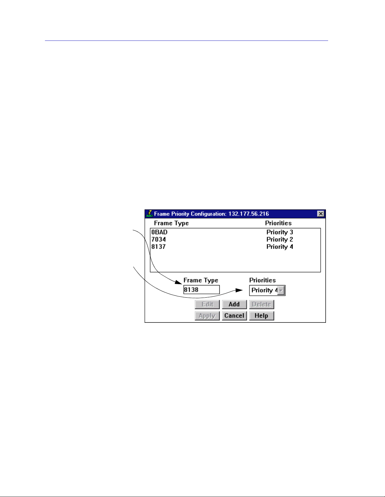
The SmartSwitch 2000 Chassis View
2. Click on the Priority drop-down list box, and scroll to select the new priority
level (Normal–7) for forwarding packets received with the specified MAC-layer
information.
3. Click the Apply button. The Current Priority Entries list box will be updated
with the newly edited entry.
To clear a priority entry from the ctPriorityExtMACTable:
1. Highlight the desired entry in the Current Priority Entries list box, and click on
the Delete button. The entry fields will be cleared from the table.
Configuring Priority Queuing Based on Packet Type
You can use the Frame Priority Configuration window, Figure 2-20, to determine
packet queuing based solely upon its Type field data. Frame type entries are
maintained in the ctPriorityExtPktTypeTable. You can configure up to 15 frame
Type priority entries for the device.
Click Add to activate the Frame
Type field, then type in the 2
byte hexadecimal frame Type.
Use the drop-down list box to
select a priority (Normal–7)
associated with that frame Type.
Click Apply to set the priority at
the device. Any priority of 1 or
higher will allow packets
received at the chosen port to
be forwarded from the higher
priority transmission queue.
Figure 2-20 . The Frame Priority Configuration Window
To assign a transmit priority based on frame Type information:
1. Click on the Add button. The entry fields will be activated.
2. Click in the Frame Type text box, and type in the 2-byte frame Type in XXXX
format, where X is a valid hexadecimal value (A-F or 0-9), for which you want
to configure a transmit priority (e.g., 8137 for Novell Type 1 frames).
3. Click on the Priority drop-down list box, and scroll to select the desired
priority level (Normal–7) for forwarding packets received with the specified
Type field information.
2-52 Managing the Hub
Page 73

NOTE
The SmartSwitch 2000 Chassis View
Since the SmartSwitch 2000 has two transmit queues, a priority of Normal will cause
packets to be forwarde d through the lower priority queue, and any pr i or it y of 1 through 7
will cause the packets to be forwarded through the higher priority queue.
4. Click Apply. The Frame Type Entries list box will be updated with the newly
created entry.
You can edit an existing frame Type entry by changing its previously assigned
priority.
1. Highlight the desired entry in the Current Priority Entries list box, and click on
the Edit button. The Priorities drop-down list box will be activated (the Frame
Type cannot be edited once it is initially configured).
2. Click on the Priority drop-down list box, and scroll to select the desired
priority level (Normal–7) for forwarding packets received with the specified
frame Type information.
3. Click the Apply button. The Frame Type Priorities Entries list box will be
updated with the newly edited entry.
To clear a priority entry from the ctPriorityExtPktTypeTable:
1. Highlight the desired entry in the Frame Type Priorities Entries list box, and
click on the Delete button. The entry fields will be cleared from the table.
The System Resources Window
The System Resources window displays current physical and logical s ystem
resources and utilization on your Sm artSwitch 2000.
To display th e System Resources window:
1. Click on D
2. Select System
opens.
evice in the Chassis View menu bar to display the Device menu.
Resources. The System Resources window, Figure 2-21,
Managing the Hub 2-53
Page 74

The SmartSwitch 2000 Chassis View
Figure 2-21. The System Resources Window
CPU Type
Displays the type and speed (in mega-hertz) of the CPU (processor) used by the
system.
Flash Memory Installed:
Displays the total amount of installed flash memory (in Mbytes).
Flash Memory Available:
Displays (in Kbytes) the current amount of flash memory that is currently free
and not currently being used for code and data.
DRAM Installed:
Displays the total installed local memory or (DRAM) in Mbytes.
DRAM Available:
Displays (in Kbytes) the current amount of local memory (DRAM) that is
currently free and not currently being used for code and data.
SRAM Installed:
Displays the total amount of shared memory (SRAM) that is installed (in Mbytes).
SRAM Available:
Displays (in Kbytes) the current amount of shared memory (SRAM) that is free
and not currently being used for data.
NVRAM Installed:
Displays (in Kbytes) the total insta lled non-volatile memory (NVRAM).
2-54 Managing the Hub
Page 75

The SmartSwitch 2000 Chassis View
NVRAM Available:
Displays (in Bytes) the current amount of non-volatile memory (NVRAM) that is
free and not currently being used for data.
Current Switch Utilization:
Displays the current load on the switch, which is based on a percentage of
maximum switching capacity of 100%.
Peak Switch Utilization:
Displays the peak percentage of switch load (based on a maximum of 100%) that
has occurred on the switch, since power-up or last reset, along with the time and
date that it occurred. This field can be administratively refreshed, as described
below.
Reset Peak Switch Utilization:
This option allows you to clear the Peak Switch Utilization field.The Peak Switch
Utilization field will immediately display the current switch utilization, and
current date and time.
To reset peak switch utilization:
1. Click on next to the Reset Peak Switch Utilization field and select Yes
from the drop down list. (The default value is No.)
2. Click on the Apply button to reset the displayed peak switch utilization. Note
that when the window refreshes the value in this field will return to No.
The value displayed as peak switch utilization will be reset to the current
value. The time and date will be reset to the current time and date. These
values will change only if a peak is experienced after this reset, or if you reset
this value again.
The default setting for this field is No. While No is selected the peak switch utilization
NOTE
value will not be reset when you click on the Apply button. You must choose Yes for a
reset to take place.
CPU Management Reservation:
Displays the desired amount of CPU bandwidth reserved for management
purposes: none, limited, or full. Bandwidth that is not reserved for management
will be devoted to switching.
Reserving CPU Bandwidth
Depending on your needs and the main function of your SmartSwitch 2000 you
may wish to change the amount of CPU bandwidth that is currently reserved for
management purposes. The three po ssible allocations of CPU band width on your
SmartSwitch 2000 are:
Managing the Hub 2-55
Page 76

The SmartSwitch 2000 Chassis View
• none — the SmartSwitch 2000 will reserve all bandwidth for switching;
therefore, if all the bandwidth is needed for switching, management frames
may be dropped.
• limited — the management of the SmartSwitch 2000 may appear slow while
the SmartSwitch 2000 is at maximum switching load.
• full — management of the SmartSwitch 2000 is always possible and
management frames will have priority over switch ed data if ful l CPU
bandwidth is required (switched frames may be dropped).
To configure the CPU Management Reservation:
1. Next to the CPU Management Reservation field click on and select none,
full, or limited from the drop down list.
2. Click on the Apply button to set the new CPU management reservation. A
window opens stating the set was successful.
802.1Q VLANs
NOTE
What is a VLAN?
This section introduces and describes pre-standard IEEE 802.1Q port-based
Virtual Local Area Network (VLAN) technology and the windows used to
configure 802.1Q VLAN-capable devices. SmartSwitch 2000 firmware version
4.00.08 supports the pre-standard IEEE 802.1Q draft specification for port-based
VLANs.
For SmartSwitch 2000 firmware versions 4.00.08 and above, HSIM-F6 modules cannot
be installed in a SmartSwitch 2000 that is operating in 802.1Q mode.
A Virtual Local Area Network (VLAN) is a logical group of devices that function
as a single Local Area Network segment (broadcast domain). Devices comprising
a VLAN may be (physically) widely separated, allowing users located in separate
areas or connected to separate ports to belong to a single VLAN group. Users
assigned to a VLAN can send and receive broadcast and multicast traffic as
though they were all physically connected to a single network segment.
VLAN-capable switches isolate broadcast and multica st tra ffic received from
VLAN groups, and contain broadcasts and multicasts from members of a VLAN
within that group.
2-56 Managing the Hub
Page 77

What is an 802.1Q Port-Based VLAN?
Switches that support the pre-standard IEEE 802.1Q draft specification for
port-based VLANs act by classifying frames into VLAN membership. Usually,
VLAN classification is based on tag headers (VLAN tags) in the headers o f data
frames. The tag header is inserted into the frame directly after the Source MAC
address field. A four-byte field in the tag header is used as the VLAN identifier.
These VLAN tags are added to data frames by the switch as the frames are
transmitted and/or received by certain ports, and are later used to make
forwarding decisions by the switch and other 802.1Q switches. In the absence of a
VLAN tag, a frame is assigned VLAN membership according to the VLAN
configuration of the switch port that receives the frame.
About 802.1Q VLAN Configuration and Operation
An 802.1Q VLAN is defined by assigning it a uniqu e identif ica tion number (the
VLAN ID) and an optional name. The VLAN ID is used to identify data frames
that originate from, and are intended for, the ports assigned to the VLAN. Up to
64 VLANs may be created, with VLAN IDs ranging from 2-4094. VLAN ID 1 is
reserved for the Default VLAN.
The SmartSwitch 2000 Chassis View
NOTE
NOTE
Ports on 802.1Q switches are assigned membership in a VLAN by associa ting a
VLAN ID with each port on the switch. The VLAN ID is combined with the port’s
identification (e.g., device X port X) to form the Port VLAN ID (PVID).
When 802.1Q mode is initially activated on a device, all ports are associated with the
Default VLAN (VLAN ID 1). If a VLAN ID has not been assigned to a particular port
on an 802.1Q switch, any frames received from that port will be classified as belonging to
the Default VLAN.
When 802.1Q is implemented for a SmartSwitch 2000 that has an HSIM-A6DP
installed, each LEC will be represented as an individual port which can be easily
assigned membership in a VLAN.
For SmartSwitch 2000 firmware version 4.00.08 and above, the number of LECs
supported by the HSIM-A6DP in 802.1Q mode is limited to 32.
Once VLANs have been configured and activated, all frames with unknown
destination addresses (including broadcast, unknown multicast, and unknown
unicast frames) will be contained within the VLAN of their origin. The switch’s
Filtering Database tracks the associations between MAC addresses, VLAN
eligibilities, and port numbers, and is used to make forwarding decision s f or
frames. All VLANs share a single Spanning Tree.
Managing the Hub 2-57
Page 78

The SmartSwitch 2000 Chassis View
Ingress List Operation
A port’s ingress list specifies the VLAN with which received frames will be
associated. The switch’s Filtering Database tracks the associations between VLAN
eligibilities, MAC addresses, and port numbers.
Untagged frames received by an 802.1Q switch port are classif ied accor ding to the
VLAN membership of the port that receives the frame.
Tagged frames received by an 802.1Q switch port are classified according to the
VLAN indicated in their tag header. A port may receive a tagged frame that
specifies a VLAN other than the one assigned to the port.
Egress List Operation
Each port’s egress list specifies which VLANs are associated with the port, and
specifies what type of frame (tagged or untagged) to transmit for each particular
VLAN on a port. This information may be statically defined by the user, or
dynamically learned and maintained by the switch’s Filtering Database.
If a port receives a tagged frame that specifies a VLAN other than the one
assigned to the port, the switch will dynamically associate that frame’s source
address and VLAN with the port (i.e., add that frame’s VLAN to the receiving
port’s egress list). Dynamically learned VLANs are subject to the same aging rules
as source addresses (e.g., if a tagged frame belonging to a dynamically learned
VLAN is not received by the port within the switch’s aging time, the transmitting
station’s source address and VLAN will be aged out for that port; no unknown
destination frames belonging to the station’s VLA N will be transmitted through
the port until the VLAN is dynamically learned once again). Only tagged frames
can cause the switch to dynamically change a port’s egress list.
802.1Q Port Types
Each 802.1Q switch port is assigned a mode of opera tion. Port types include:
1Q Trunk
If VLAN membership is to apply to users across several switches, ports used to
connect 802.1Q-aware devices ar e configured to use 1Q Trunk mode. In this mode,
all frames (except BPDUs) are transmitted with a tag header included in the
frame, allowing VLAN frames to maintain their VLAN ID across multiple
switches. Any untagged frames received by the port ar e dropped. 1Q Trunk ports
are configured to be members of all VLANs.
1d Trunk
This mode allows a port to transmit to a traditional (802.1d) switch fabric . These
ports transmit only untagged frames, and the switch expects to receive only
untagged traffic through the port. 1 d Trunk ports are configured to be members of
all VLANs. This mode can be used to share a connection among multiple VLANs
(e.g., sharing a server between two or more separate VLANs).
2-58 Managing the Hub
Page 79

Hybrid
Hybrid mode (enabled by default) allows a port to receive and transmit both
tagged and untagged frames. In this mode, the port will be a member of its
statically assigned VLAN, as well as any dynamically learned VLANs (remember ,
dynamically learned VLANs are subject to the same aging rules as source
addresses).
Configuring Your 802.1Q VLANS
Before you can define and configure 802.1Q port-based VLANs on your device,
you must activate the device’s 802.1Q operational mode; this operation can be
performed using Local Management or the MIB Tools application. Using MIB
Tools, 802.1Q mode can be activated through the Container MIB’s Logical Entry
Table (contLogicalEntryTable). When the 802.1Q component is activated, the device
will automatically reset, and begin operatin g in 802.1Q mode.
Your SmartSwitch 2000 will automatically reset when 802.1Q mode is activated. If you
!
CAUTION
attempt to activate the 802.1Q component via the MIB Tools application, you may lose
contact with the rest of the chassis once the device resets. We recommend that Local
Management be used to activate 802.1Q mode for SmartSwitch 2000 devices.
The SmartSwitch 2000 Chassis View
Refer to your device’s Local Management documentation for instructions on
activating a device’s 802.1Q operational mode via Local Management. For details
on the MIB Tools application, refer to your Tools Guide.
To set up your 802.1Q port-based VLANs using NetSight Element Manager, you
must first define the desired VLANs using the VLAN Config window
(Figure 2-22), which allows you to assign VLAN IDs and optional VLAN na mes,
and enable or disable VLANs.
After your VLANs are defined, you may configure the ingress and egress lists for
each port using the VLAN Port Config window (Figure 2-23) and the VLAN
Egress Port Config window (Figure 2-24), respectively.
Setting VLAN Parameters and Operational Modes
802.1Q VLANs are defined using the VLAN Config window, which is accessed
from the D
1. Click on D
2. Click on 802.1Q V
Config window, Figure 2-22, opens.
evice menu in your switch’s Chassis View. To launch the w indow:
evice in the Chassis View menu bar to display the Device menu.
LAN, and then select 802.1Q VLAN Config. The VLAN
Managing the Hub 2-59
Page 80

The SmartSwitch 2000 Chassis View
Figure 2-22. The VLAN Config Window
The Configured VLANS list box and fields allow you to view, create, modify,
delete, enable, and disable 802.1Q port-based VLANs. The list box displays the
following information about your defined VLANs:
VLAN ID
The VLAN ID is used to identify data frames that originate from, and are
intended for, the ports assigned to the VLAN. Up to 64 VLANs may be created,
with VLAN IDs ranging from 2-4094. The VLAN ID is combined with the port’s
identification (e.g., device X port X) to form the Port VLAN ID (PVID). VLAN ID
1 is reserved for the Default VLAN.
VLAN Name
An optional 32-character VLAN name may be assigned to a created VLAN. The
Default VLAN is assigned the name DEFAULT VLAN, which cannot be changed
or deleted.
Admin Status
This field indicates whether the VLAN is enabled or disabled. Unless Enable is
selected when port-based VLANs are initially defined, they are disabled by
default. The Default VLAN cannot be disabled.
2-60 Managing the Hub
Page 81

NOTE
The SmartSwitch 2000 Chassis View
Creating and Modifying VLANs
The fields immediately below the Configured VLANS list box are used to create
and modify your port-based VLANs. To create a new VLAN:
1. In the VLAN ID field, enter a unique value between 2-4094. VLAN ID 1 is
reserved for the Default VLAN, and cannot be used.
2. If desired, enter a name for the VLAN in the VLAN Name field. VLAN names
must be 32 characters or less.
Unless Enable is selected when a port-based VLAN is initially defined, it will be disabled
by default. A new VLAN that is left in a Disabled state will remain disabled until a port
is assigned to it, at which time it will be automatically enabled. If you are changing a
VLAN’s port assignment, the VLAN should be disabled before changing the port
configuration. See Enabling and Disabling VLANs, on page 2-62, for instructions on
disabling VLANs. See Performing Ingress List Configuration, on page 2-62, for
details on completing your VLAN port configuration.
3. Click Apply. The new VLAN will be added to the Configured VLANS list box.
Once a VLAN has been created, its VLAN ID cannot be modified. If you wish to
change a VLAN’s ID, you’ll have to delete the VLAN and create a new entry. See
Deleting VLANs, on page 2-61, for instructions on deleting a VLAN. Attempting
to change a VLAN’s ID will result in the creation of a new VLAN with the same
VLAN name.
To modify an existing VLAN’s name, select its entry in the Configured VLANS
list box. The selected VLAN’s name will be displayed in the VLAN Name field.
Modify the displayed name as outlined in Steps 2-3, above.
Deleting VLANs
The VLAN Config window also allows you to delete VLANs (except for the
Default VLAN, which cannot be deleted). When a VLAN is deleted, any ports
assigned to that VLAN will automatically become members of the Default VLAN.
To delete a VLAN from your 802.1Q switch:
1. Click to select the desired VLAN entry in the Configured VLANS list box.
2. Click Delete. The selected VLAN will be removed from the list box.
Managing the Hub 2-61
Page 82

The SmartSwitch 2000 Chassis View
Enabling and Disabling VLANs
Unless Enable is selected when a VLAN is initially defined, it is disabled by default. A
NOTE
new VLAN that is left in a Disabled state will remain disabled until a port is assigned to
it, at which time it will be automatically enabled. If you are changing a VLAN’s port
assignment, the VLAN should be disabled before changing the port configuration. See
Performing Ingress List Configuration, on page 2-62, for details on completing your
VLAN port configuration.
1. Select the desired VLAN entry in the Configured VLANS list box.
2. In the VLAN Admin field, click to select Enable or Disable.
3. Click the Apply button. The selected VLAN will be enabled or disabled,
depending on your selection.
Updating VLAN Config Window Information
Clicking the Refresh button will update the information displayed in the
Configured VLANs list without closing the wind ow.
Performing Ingress List Configuration
802.1Q VLAN port assignment and ingress list configurati on operations are
performed using the VLAN Port Config window, which is accessed from the
evice menu in your switch’s Device View. See Ingress List Operation, on
D
page 2-58 for details on ingress lists. To launch the window:
1. Click on D
evice in the Chassis View menu bar to display the Device menu.
2. Click on 802.1Q V
VLAN Port Config window, Figure 2-23, opens.
LAN, and then select 802.1Q VLAN Port Config. The
2-62 Managing the Hub
Page 83

The SmartSwitch 2000 Chassis View
Figure 2-23. The VLAN Port Config Window
The 802.1Q VLAN Port Assignment list box in this window displays the
following information about ports on your 802.1Q switch:
Slot/Port
These fields display the slot and port index for each port on your 802.1Q switch.
For the SmartSwitch 2000, the slot index will always be 1.
VLAN ID
This field displays the VLAN ID of the VLAN to which the port is currently
assigned.
Mode
This field displays the port’s current mode of operation. Port operational modes
include:
• Dot1DTrunk mode, which is used for ports that are to connect to a traditional
(802.1d) switch fabric. These ports transmit only untagged frames. 1d Trunk
ports are configured to be members of all VLANs.
• Dot1QTrunk mode, which is used for ports used to connect 802.1Q-aware
devices if VLAN membership is to apply to users across several switches.
These ports transmit only tagged frames. 1Q T runk ports ar e configured to be
members of all VLANs.
Managing the Hub 2-63
Page 84

The SmartSwitch 2000 Chassis View
• Hybrid mode, which allows a port to receive and transmit both tagged and
untagged frames. In this mode, the port will be a member of its statically
assigned VLAN, as well as any dynamically learned VLANs. Hybrid mode is
enabled by default.
For more information on 802.1Q port operational modes, see 802.1Q Port Types,
on page 2-58.
Discard
This field displays the port’s current frame discard format (discardTagged,
discardUntagged, or noDiscard).
The VLAN ID, Port Operational Mode, and Port Discard fields, below the list
box, allow you to configure your ports as foll ows:
VLAN ID
This field allows you to associate a selected port with an existing VLAN. See
Assigning VLAN Membership to Ports, on page 2-64, for details on performing
this operation.
Port Operational Mode
This field allows you to assign a mode of operation to a selected port. See Setting
Port Operational Modes, on page 2-65, for details on using this field.
NOTE
Port Discard
This field allows you to specify the frame discard format (discardTagged,
discardUntagged, or noDiscard) for a selected port. See Setting Port Frame
Discard Formats, on page 2-65, for details on using this field.
Assigning VLAN Membership to Ports
To assign a port on your 802.1Q switch to any of your defined VLANs:
1. In the list box, click to select a port that you wish to assign to a VLAN. The
port’s current VLAN configuration information, including its VLAN ID, will be
displayed in the fields below the list box.
2. In the VLAN ID field, click to select the VLAN ID of the VLAN to which you
wish to assign the selected port.
3. Click the Apply button. The new VLAN assignment will be reflected in the
VLAN Port Config window’s list box for the selected port.
If you assign a port to a VLAN that is in a Disabled state, the VLAN will automatically
be Enabled once the port assignment operation has been completed.
2-64 Managing the Hub
Page 85

The SmartSwitch 2000 Chassis View
Setting Port Operational Modes
T o assign a port operational mode (dot1dTrunk, dot1QT runk, or hybrid) to a port
on your 802.1Q switch:
1. In the VLAN Port Config window’s list box, click to select a port to which you
wish to assign a port operatio nal mode.
2. In the Port Operational Mode field, click to select the desired operational
mode.
3. Click the Apply button. The selected mode will be reflected in the list box for
the selected port.
Setting Port Frame Discard Formats
To assign a frame discard format (discardTagged, discardUntagged, or
noDiscard) to a port on your 802.1Q switch:
1. In the VLAN Port Config window’s list box, click to select a port to which you
wish to assign a frame discard format.
2. In the Port Discard field, click to select the desired frame discard format.
3. Click the Apply button. The selected mode will be reflected in the list box for
the selected port.
Updating VLAN Port Config Window Information
Clicking the Refresh button will update the information displayed in the 802.1Q
VLAN Port Assignment list without closing the window.
Performing Egress List Configuration
802.1Q VLAN switching allows each port on a switch to transmit traffic for any or
all defined VLANs on your network. During egress list configuration, you
determine which VLANs are on each port’s egress list. See Egress List Ope ration,
on page 2-58 for details on egress lists.
Egress list configuration operations are performed using the VLAN Egress Port
Config window. To launch t he window:
1. Click on Device in the Chassis View menu bar to display the Device menu.
2. Click 802.1Q VLAN, and then select 802.1Q VLAN Egress Port Config. The
VLAN Egress Port Config window, Figure 2-24, opens.
Managing the Hub 2-65
Page 86

The SmartSwitch 2000 Chassis View
Figure 2-24. The VLAN Egress Port Confi g Window
The list box at the top of this window is used to select a configured VLAN for
association with your swit ch’s ports. Clicking on a VLAN will display its
currently associated ports in the lower portion of this window. The list box
displays the following information:
Slot Number
This field displays the slot index for the device being configured.
VID
This field lists the VLAN IDs of the currently configured VLANs on your switch.
Name
This field lists the VLAN names assigned to the currently configured VLANs on
your switch.
2-66 Managing the Hub
Page 87

The SmartSwitch 2000 Chassis View
Under the list box there are two groups of check boxes that display the ports on
the switch. A checkmark in the port’s check box indicates that the VLAN selected
in the list box is in the port’s egress list. The two groups are:
Egress Ports
Use these check boxes to add or remove the selected VLAN fr o m the egr e ss list of
one or more ports.
Egress Untagged List
Use these check boxes to allow the ports to transmit untagged frames from the
selected VLAN.
Building an Egress List
1. In the list box at the top of the window, click to select a configured VLAN. The
ports that contain the selected VLAN in their egress lists will be displayed in
the lower portion of the window with checkmarks in their check boxes.
2. To add or remove the selected VLAN from the egress list of one or more ports,
click on the appropriate check box in the Egress Po rts group . A checkmark in
a port’s check box indicates that the selected VLAN is in the port’s egress list.
3. To add or remove the ability for a port to transmit both tagged
frames from the selected VLAN, click to put a checkmark in the appropriate
check box in the Egress Untagged List group. Note that a port check box in
this group will be grayed out until it has been selected in the Egress Ports
group.
4. To apply any changes, click on the Apply button at the bottom of the window.
Broadcast Suppression
You can monitor and suppress the amount of broadcast frames received on each
interface on your SmartSwitch 2000; therefore, protecting your network from
broadcast storms. Specifically, you can monitor the number of frames each
interface is receiving, and set limits on how many of those broadcast frames will
be forwarded to the other interfaces. O nce a threshold has been reached on an
interface, broadcast frames will be dropped. From the Broadcast Statistics and
Suppression window, you can set a unique threshold for each interface on a
frames per second basis.
To access the Broadcast Statistics and Suppression window:
1. Click on D
or
and
untagged
evice in the Chassis View menu bar to display the Device menu.
Click on the SmartSwitch 2000 module index. The Module Menu opens.
Managing the Hub 2-67
Page 88

The SmartSwitch 2000 Chassis View
2. Select Broadcast Suppression. The Broadcast Statistics and Suppression
window, Figure 2-25, opens.
Figure 2-25. The Broadcast Statistics and Suppression Window
Port #
This read-only field indicates the number assigned to each interface on the device.
Total RX
Displays the total number of broadcast frames received on the interface since the
device was last initialized.
Peak Rate
The peak rate of broadcast fram es (in frames per seco nd) r eceived on the interface
since the device was last initialized or the peak value was administratively reset
through this window.
Time Since Peak
The time (in a days, hh:mm:ss format) that the peak broadcast rate occurred; that
is, the system uptime (MIB-II) at the time the peak occurred. This value will be
reset to 0 days, 00:00:00 when the device is re-initialized or when you
administratively reset the peak values.
2-68 Managing the Hub
Page 89

TIP
The SmartSwitch 2000 Chassis View
In order to calculate the time since peak, subtract the value in the Time Since Peak column
from the current sysUpTime displ ayed as Up Time in the front panel . Plea se note that t he
peak time you calculate will be within 5 minutes of the actual time since peak, as
sysUpTime is polled by default at 3 minute intervals and the broadcast suppression values
are polled by default at 2 minute intervals.
To reset the Peak Rate and Time Since Peak values:
1. Shift-click to select one or more interfaces for which you want to reset the
values.
2. Click on the Reset Peak Rate and Peak Time on Selected Ports: drop-down
list box, and drag to select YES.
3. Click on the Apply button. The Peak Rate and Time Since Peak values will be
reset for the selected interfaces.
Threshold
The maximum number of received broadcast frames that may be forwarded by
this interface to other interfaces on the device. Any number of broadcast frames
received over this threshold will be dropped. Th e default value for the interface is
near the theoretical maximum frames per second for the interface, i.e., 14,880 for
10Mb Ethernet interface, 148,880 for 100Mb Ethernet or 1,488,800 for Gigabit
Ethernet.
NOTE
To change the Receive Broadcast Threshold:
1. Shift-click to select one or more interfaces for which you want to change the
broadcast packet threshold.
2. Highlight the value currently in the Receive Broadcast Threshold on
Selected Ports: field and type in a new broadcast threshold value. Allowable
values begin at 10 and proceed in multiples of ten.
When you enter a value less than 10, the threshold will default to a value of 0. If you enter
a value that is not a multiple of 10 it will round down to the last multiple of 10, i.e., if you
enter 15 as the new threshold value, the threshold value will be set to 10; if you enter 49 as
the new threshold value, the threshold value will be set to 40.
3. Click on the Apply button. The new threshold will be applied to the selected
interfaces. Any broadcast frames received by the interface exceeding the set
threshold will be dropped.
Managing the Hub 2-69
Page 90
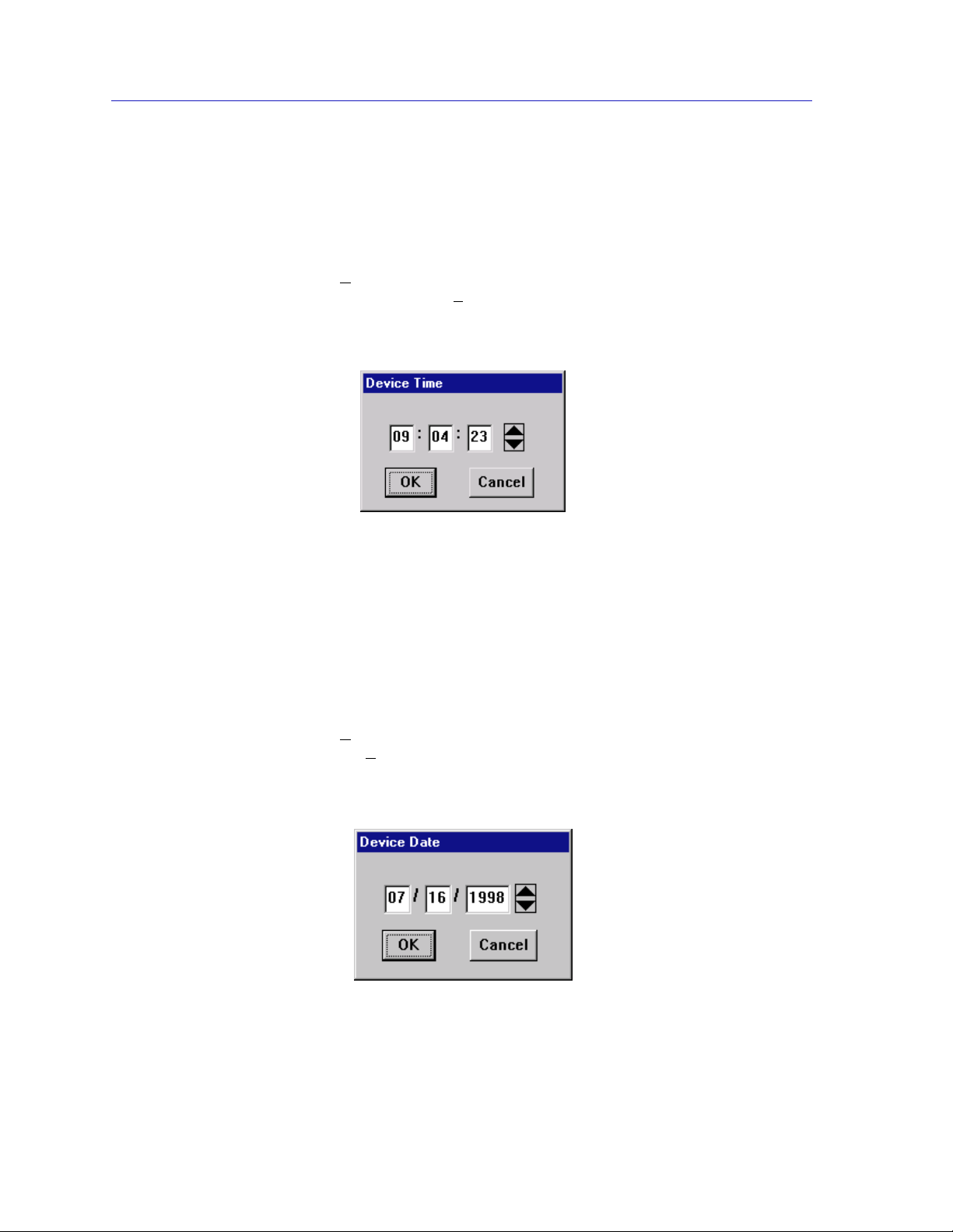
The SmartSwitch 2000 Chassis View
Setting the Device Date and Time
Y ou can select the Edit Device T ime an d Edit Device Date options from the menu
to change the date and time stored in the device’s internal clock.
To edit the device time:
1. Click on D
menu. Click Edit Device T
2. The following change window, Figure2-26, opens.
3. Enter the new time in a 24-hour hh:mm:ss format, either by highlighting the
field you wish to change and using the up and down arrow buttons, or by
simply entering the new value in the appropriate field.
4. Click on the OK button to save your changes, or on the Cancel button to
cancel.
To edit the device date:
evice on the Chassis View window menu bar to access the Device
ime.
Figure 2-26. The Edit Time Window
1. Click on D
menu. Click E
2. The following change window, Figure2-27, opens.
evice on the Chassis View window menu bar to access the Device
dit Device Date.
Figure 2-27. The Edit Date Window
2-70 Managing the Hub
Page 91

3. Enter the new date in a mm/dd/yyyy format, either by highlighting the field you
wish to change and using the up and down arrow buttons, or by simply
entering the new value in the appropriate field.
4. Click OK to save your changes, or on the Cancel button to cancel.
Enabling and Disabling Ports
When you disable bridging at a port, you disconnect that port’s network from the
bridge entirely. The port does not forward any packets, nor does it participate in
Spanning Tree operations. Nodes connected to the network can still communicate
with each other, but they can’t communicate with the bridge or with other
networks connected to the bridge. When you enable a port, the port moves from
the Disabled state through the Learning and Listening states to the Forwarding
state; bridge port state color codes will change accordingly.
From the Port menus in the SmartSwitch 2000 Chassis View, you can enable and
disable any individual ports:
1. Click on the desired Port index. The Port menu displays.
The SmartSwitch 2000 Chassis View
NOTE
2. Select Enable to enable the port, or Disable to disable the port. Your port will
now be enabled or disabled as desired.
For more information about bridging functions and how to determine the current state of
each bridge port, see the Bridging chapter in the Tools Guide.
From the Module menu in the SmartSwitch 2000 Chassis View, you can enable or
disable bridging at the device level:
1. Click on the Module Index in the chassis display. The Module menu opens.
2. Click on Enable Bridge to restart bridging at the device level, or Disable
Bridge to halt bridging across the entire device.
Managing the Hub 2-71
Page 92

The SmartSwitch 2000 Chassis View
2-72 Managing the Hub
Page 93

Chapter 3
Alarm Configuration
Accessing the Basic and Advanced Alarms windows; creating a basic alarm; creating an advanced
alarm; creating events; assigning actions to events; viewing the event log
You can configure alarms and events (and, where appropriate, actions) for each
available interface through the RMON Alarm and Event functionality supported
by your SmartSwitch 2000.
The Alarm, Event, and Actions windows described in this chapter are identical to those
TIP
provided via the RMON utility. For more information about other features of RMON, see
the RMON User’s Guide.
About RMON Alarms and Events
Although Alarms and Events are defined as separate RMON groups, neither one
can function properly without the other: you can define an alarm threshold, but if
it doesn’t point to an event, there will be no indication that the threshold has been
crossed; similarly, you can define an event, but unless it is attached to an alarm
threshold, it won’t be triggered. Each is an essential part of the same notification
process: the alarm defines a set of conditions you want to know about, and the
event determines the means of letting you know those conditions have occurred.
Events are also an integral part of the filter and packet capture functionality: you
can start and stop packet capturing in response to events, or a successful pa cket
capture can generate its own event.
NetSight Element Manager provides two means for configuring RMON alarms:
using the Basic Alarms window, you can define both rising and falling alarm
thresholds for up to three pr e-selected MIB-II va riables per interf ace; based on the
options you select, the application auto matically creates the necessary events (to
log alarm occurrences, generate a trap, or both) and — for devices which support
the Actions MIB — adds the requested actions to those events (to enable or
disable bridging at the selected interface).
3-1
Page 94

Alarm Configuration
TIP
Using the Advanced Alarms feature, you can define custom alarms for almost any
MIB-II or RMON object, as long as it is present in the devi ce firmware and its
value is defined as an integer (including counters, timeticks, and gauges). All
aspects of these alarms are user-selectable: thr esholds can be established on either
the absolute or delta value for a variable; events can be configured to create a log,
generate a trap, or both; and for Enterasys devices that support the Actions MIB,
events can also be configured to perform any defined SNMP SET or series of SETs
on device objects. The Advanced Alarms feature also allows you to configure any
events you wish to use in conjunction with the Packet Capture functionality. (For
more information on using the Packet Capture feature, see the RMON User’s
Guide included with your software.)
The Basic Alarms feature allows you to assign alarms to any interface type; using
the Advanced Alarms feature, you need only be sure to select variables
appropriate to the interface — Ethernet for Ethernet, Token Ring for Token Ring,
etc. — when defining your alarms.
You can use th e RMON Alarms feature to configu re alarms for MIB objects on FDDI,
ATM, and other interfaces that don’t specifically support RMON: the Basic Alarms
window provides MIB II objects as alarm variables; Advanced Alarm configuration allows
you to select any object as an alarm variable, as long as its value is defined as an integer
and you assign the correct instance value. See step 5 on page 3-18 and the Note which
follows it for more information on assigning the correct instance value to an advanced
alarm.
Basic Alarm Configuration
Using the Basic Alarm Configuration application, you can define both rising and
falling alarm thresholds for three selected MIB-II objects: ifInOctets, ifInNUcast,
and ifInErrors. Because these pre-selected objects are not RMON-specific, you can
configure alarms for all interfaces installed in your SmartSwitch 2000 — including
those, like FDDI, for which no specific RMON statist ics currently exist.
In addition to configuring separate rising a nd f alling thresholds, you can also
configure your device’s response to an alarm condition: when a threshold is
crossed, the RMON device can create a log of alarm events, send a trap notifying
your management workstation that an alarm condition has occurred, or both; you
can even configure an alarm to enable or disable bridging on the off ending port in
response to a rising or falling alarm condit ion.
The Basic Alarm Configuration window combines the three parts of creating a working
TIP
alarm — configuring the alarm itself, configuring an event that will announce the
occurrence of an alarm (including assigning any actions), and linking the two — into a
single step, and handles the details transparently. For more information about t he
individual steps involved in creating an alarm, see Advanced Alarm Configuration, on
page 3-10.
3-2 Basic Alarm Configuration
Page 95

Accessing the Basic Alarm Configuration Window
To access the RMON Basic Alarm Configuration window:
1. From the Chassis View, click on the appropriate port interface to display the
Port menu.
2. Select Alarm Configuration. The RMON Basic Alarm Configuration window,
Figure 3-1, opens.
Alarm Configuration
Figure 3-1. The RMON Basic Alarm C onfiguration Window
You can also access the Alarms function — and the rest of t he RMON functionality — b y
TIP
selecting the RMON option from the Chassis View Utilities menu.
When the window is first launched, no interfaces will be selected, and the Apply,
Disable, and View Log buttons will be grayed out: the Apply and Disable
buttons will activate when an interface is selected; the View Log button will
activate when an interface which has experienced an alarm event is selected. The
presence of an event log is indicated by the double greater-than sign (>>)
displayed to the left of the threshold value that was crossed.
Basic Alarm Confi gura tion 3-3
Page 96

Alarm Configuration
Viewing Alarm Status
The Basic Alarm Configuration window contains all the fields you need to
configure one or more of the three basic alarms available for each interface
installed in your RMON device:
Kilobits — Total Errors — Broadcasts/Multicasts
Use these fields at the top of the window to change the alarm type whose status is
displayed in the list box. For example, if the Kilobits option is selected, the
information in the list box pertains to the status of the Kilobits alarm type for each
installed interface. Before you configure an alarm or alarms, be sure the
appropriate option is selected here.
The available alarm variables are:
• Kilobits (ifInOctets) — tracks the number of octets of data received by the
selected interface. Note that this value has been converted for you fr om octets
(or bytes) to kilobits (or units of 125 bytes); be sure to enter your thresholds
accordingly. For example, to set a rising th reshold of 1250 octets, enter a
threshold value of 10; to set a falling threshold of 625 octets, enter a thre shold
value of 5.
TIP
• Total Errors (ifInErrors) — tracks the number of error packets received by the
selected interface.
• Broadcast/Multicast (ifInNUcast) — tracks the number of non-unicast — that
is, broadcast or multicast — packets received by the selected interface.
The three pre-selected alarm variables are all MIB II variables; this allows you to configure
alarms for any installed interface — even those for which no specific RMON statistics
exist.
Port Number
Provides a sequential indexing of the interfaces installed in your RMON device.
IF Number
Displays the interface number assigned to each available interface.
IF Type
Displays each interface’s type: FDDI, Ethernet, Token Ring, or ATM. Not e that
there is no type distinction between standard Ethernet and Fast Ethernet.
Status
Displays the current status of the selected alarm type for each interface: Enabled
or Disabled. Remember, this status refers only to the alarm type which is selected
at the top of the window; each of the other two alarm types can have different
states.
3-4 Basic Alarm Configuration
Page 97

Alarm Configuration
Log/Trap
Indicates whether or not each alarm has been configured to create a silent log of
event occurrences and the alarms that triggered them, and whether or not each
alarm has been configured to issue a trap in response to a rising or falling alarm
condition. Possible values are log, trap, log&trap, or none.
Polling Interval
Displays the amount of time, in days, hours, minutes, and seconds, over which
the selected alarm variable will be sampled. At the end of the interval, the sample
value will be compared to both the rising and falling thresholds (described
below). You can set any interval up to 24,855 days.
Rising Th r e s h o l d
Displays the high threshold value set for the selected alarm variable. Values used
to compare to the thresholds are relative, or delta values (the difference between
the value counted at the end of the current interval and the value counted at the
end of the previous interval); be sure to set your thresholds accordingly.
Rising Action
Indicates whether or not a rising alarm occurrence will initiate any a ctions in
response to the alarm condition: Enable if bridging will be enabled at the selected
interface in response to a rising alarm, Disable if bridging will be disabl ed at the
selected interface in response to a rising alarm, and None if no actions have been
configured for the selected alarm. Note that the Action fields will be unavailable
for devices configured to operate in SecureFast switching mode.
TIP
Falling Threshold
Displays the low threshold value set for the selected alarm variable. Values used
to compare to the thresholds are relative, or delta values (the difference between
the value counted at the end of the current interval and the value counted at the
end of the previous interval); be sure to set your thresholds accordingly.
Falling Action
Indicates whether or not a falling alarm occurrence will initiate any actions in
response to the alarm condition: Enable if bridging will be enabled at the selected
interface in response to a falling alarm, Disable if bridging will be disabled in
response to a falling alarm, and None if no actions have been configured for the
selected alarm. Note that the Action fields will be unavailable for devices
configured to operate in SecureFast switching mode.
Before you decide whether or not to assign an action to a rising or falling alarm, it is
important to understand something about the hysteresis function built in to the RMON
alarm functionality. See How Rising and Falling Thresholds Work, on page 3-27, for
more information.
Basic Alarm Confi gura tion 3-5
Page 98

Alarm Configuration
The remainder of the window fields provide the means for configuring alarms for
each available interface. The information provided in this screen is static once it is
displayed; for updated information, click on the Refresh button. Adding or
modifying an alarm automatically updates the list.
Creating and Editing a Basic Alarm
The editable fields at the bottom of the Basic Alarm Configuration window allow
you to configure alarm parameters for each available interface. These fields will
display the parameters used for the most recently configured alarm (no matter
which interfaces are selected in the list box); this allows you to set the same
parameters on multiple interfaces with a single set. Hold down the Shift key
while clicking to select a contiguous group of interfaces; use the Ctrl key to select
any interfaces. To display the alarm parameters for a specific interface,
double-click on that interface.
There is no specific “Enable” function; simply configuring thre sholds and/or
actions for an alarm and applying those changes enables the alarm. For more
information on disabling an alarm, see Disabling a Basic Alarm, on page 3-8.
To configure an alarm:
1. At the top of the window, click to select the variable to be used for your alarm:
Kilobits, Total Errors, or Broadcast/Multicast. The display in the list box will
reflect the current status at each interface of the alarm type you have
selected.
2. In the list box, click to highlight the interface (or use shift-click or ctrl-click to
select multiple interfaces) for which you would like to configure an alarm for
the selected variable. Note that the editable fields will display the parameters
assigned to the most recently set alarm; however, any changes you make in
all
these fields will be set to
3. In the Interval field, enter the amount of time, in days, hours, minutes, and
seconds, over which the selected variable will be sampled. At the end of the
interval, the sample value will be compared to both the rising and falling
thresholds. You can assign any time interval up to 24,855 days. If you set an
incorrect time value (e.g., you enter 75 minutes instead of 1 hour, 15 minutes)
you will receive an error message. Click OK and ente r the correc t time value.
4. In the Alarm field, click to select one or both of the following options:
a. Select Log if you wish to create a silent log of alarm occurrences.
b. Select Trap if you want your device to issue a trap in response to each
alarm occurrence.
selected interfaces.
3-6 Basic Alarm Configuration
Page 99

NOTES
Alarm Configuration
In order for the trap selection to work properly, your SmartSwit ch 2000 must be
configured to send traps to your network managem ent station. This is accomplished via
Local Management and the Trap Table; consult your device hardware manual for more
information. If you are monitoring a variable you consider to be critical, we do not
recommend that you select Trap as the only event response; if a trap is lost due to a
collision or other transmission problem, it will not be re-sent.
5. Any value you enter in the Community field will be included in any trap
messages issued by your SmartSwitch 2000 in response to the alarm(s) you
are configuring; this value is also used to direct traps related to this alarm to
the appropriate management workstation(s):
a. If you enter a value in this field, traps related to the associated alarms
will only be sent to the network management stations in the device’s trap
which have been assigned the same community name
table
(and for
which traps have been enabled). Any IP addresses in the device’s trap
not
table which have
been assigned the same community string, or which
have been assigned no community string, will not receive traps related to
the alarm(s) you are configuring.
b. If you leave this field blank, traps related to the associated alarms will
be sent to any network management stations which have been added to
the device’s trap table, and for which traps have been enabled —
regardless of whether or not those IP addresses have been assigned a
community name in the Trap Table.
6. Click in the Rising Threshold field; enter the high threshold value for this
alarm. Compared values are always relative, or delta values (the difference
between the value counted at the end of the current interval and the value
counted at the end of the previous interval); be sure to set your thresholds
accordingly.
When configuri ng a Kilobits alarm, NetSight Element Manager converts
octets into kilobits (units of 125 bytes, or octets) for you; for example, to set a
rising threshold of 1250 octets, enter a threshold value of 10.
7. In the Rising Action field, click to select the action you want your device to
take in response to a rising alarm: Enable Port, Disable Port, or None. Note
that this action enables and disables only
bridging
at the specified port, and
not the interface itself.
For more information on how actions are triggered, see How Rising and
Falling Thresholds Work, on page 3-27.
8. Click in the Falling Th r e s h o ld field; enter the low threshold value for this
alarm. Remember, compared values are always relative, or delta values (the
difference between the value counted at the end of the current interval and
the value counted at the end of the previous interval); be sure to set your
thresholds accordingly.
Basic Alarm Confi gura tion 3-7
Page 100

Alarm Configuration
TIP
When configuri ng a Kilobits alarm, NetSight Element Manager converts
octets into kilobits (units of 125 bytes, or octets) for you; for example, to set a
falling threshold of 625 octets, enter a threshold value of 5.
9. In the Falling Action field, click to select the action you want your device to
take in response to a falling alarm: Enable Port, Disable Port, or None. Note
that this action enables and disables only
not the interface itself.
For more information on how actions are triggered, see How Rising and
Falling Thresholds Work, on page 3-27.
Remember, the Actions fields will be grayed out for devices configured to operate in
SecureFast switching mode, as there is no active bridging component on those interfaces.
10. Click Apply to set your changes. If you have made any errors in configuring
alarm parameters (using an invalid rising or falling threshold, for example, or
neglecting to supply a polling interval), either an error window with the
appropriate message displays, or a beep will sound and the cursor will blink in
the field which contains the error. Correct the noted problem(s), and click
Apply again.
bridging
at the specified port, and
Once you click the Apply button, the configured alarm parameters will be set for
every selected interface, and the alarms will automatically be enabled; the list box
display will also refresh to reflect these changes. To configure additional ala r ms,
or alarms of a differ ent type, select the a ppro priate alarm variable a t the top of th e
window, highlight the appropriate interface(s), and repeat the procedures
outlined above.
Disabling a Basic Alarm
Using the Disable button at the bottom of the window actually performs two
functions: it both disables the alarm and deletes the alarm entry (and its
associated event and action entries) from device memory to help conserve device
resources. In the list box display, the parameters for any “disabled” alarm are
automatically reset to their default values.
1. In the top of the window, click to select the variable for which you wish to
disable an alarm: Kilobits, To t al Errors, or Broadcast/Multica st.
2. In the list box display, click to highlight the interface(s) for which you wish to
disable the selected alarm type. (Remember, you can use shift-clic k to select
a sequential group of interfaces, or ctrl-click to select any group of
interfaces.)
3. Click Disable. The selected alarm type on the selec ted interface(s) will be
disabled, and the list box display will refresh to reflect those changes.
3-8 Basic Alarm Configuration
 Loading...