

Page 1
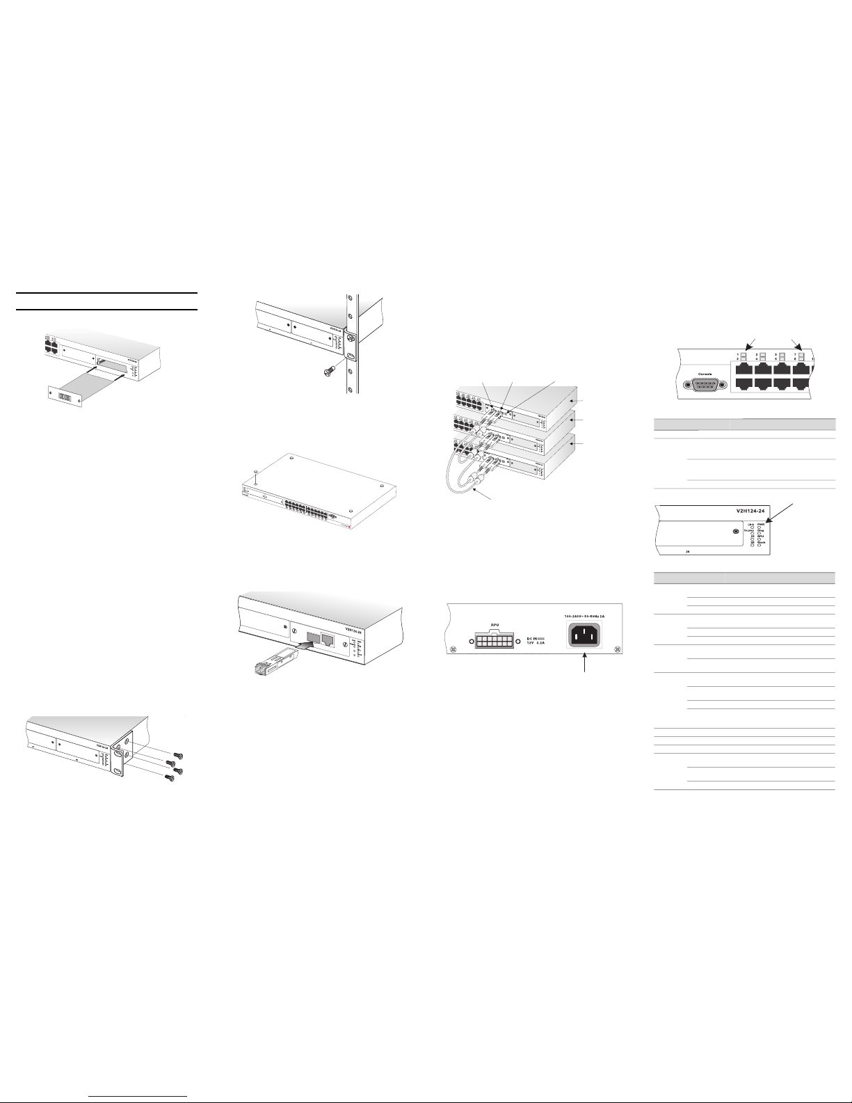
Installing an Optional Module into the Switch
Caution: DO NOT install slide-in modules with the switch powered on. Be sure you
power off the switch before installing any module.
Note: The stacking module must only be installed in slot 25.
To install an optional module into the switch, do the following:
1. Disconnect power to the switch.
2. Remove the blank metal plate (or a previously installed module) from
the appropriate port by removing the two screws with a flat-head
screwdriver.
3. With the module still in the anti-static bag, touch the metal frame of the
switch to prevent damage caused by static electricity discharge. Also, it
is recommended to use an ESD wrist strap during installation.
4. Remove the module from the anti-static shielded bag.
5. Holding the module level, guide it into the carrier rails on each side and
gently push it all the way into the port, ensuring that it firmly engages
with the connector.
Mounting
This switch can be mounted in a standard 19-inch equipment rack or on a
desktop or shelf. Mounting instructions for each type of site follow.
Installing Optional Modules: Before mounting the switch, you may want
to install optional modules. If you have purchased optional slide-in
100BASE-FX, 1000BASE-T, 1000BASE-T/SFP, or stacking modules, install
these modules now, following the instructions in the previous section.
Rack Mounting
Before rack mounting the switch, pay particular attention to the following
factors:
• Temperature: Since the temperature within a rack assembly may be
higher than the ambient room temperature, check that the rackenvironment temperature is within the specified operating temperature
range.
• Mechanical Loading: Do not place any equipment on top of a rackmounted unit.
• Circuit Overloading: Be sure that the supply circuit to the rack
assembly is not overloaded.
• Grounding: Rack-mounted equipment should be properly grounded.
Particular attention should be given to supply connections other than
direct connections to the mains.
To rack-mount devices:
1. Attach the brackets to the device using the screws provided in the
Bracket Mounting Kit.
2. Mount the device in the rack, using four rack-mounting screws (not
provided).
3. If installing a single switch only, refer to “Connecting to a Power
Source.”
4. If installing multiple switches, mount them in the rack, one below the
other, in any order.
Desktop or Shelf Mounting
1. Attach the four adhesive feet to the bottom of the first switch.
2. Set the device on a flat surface near an AC power source, making sure
there are at least two inches of space on all sides for proper air flow.
3. If installing a single switch only, refer to “Connecting to a Power
Source.”
4. If installing multiple switches, attach four adhesive feet to each one.
Place each device squarely on top of the one below, in any order.
Installing an SFP Transceiver
To install an SFP transceiver, perform the following steps:
1. Consider your network and cabling requirements to select an
appropriate SFP transceiver type.
2. Insert the transceiver with the optical connector facing outward and the
port connector facing down. Note that SFP transceivers are keyed so
they can only be installed in one orientation.
3. Slide the SFP transceiver into the port until it clicks into place.
Note: SFP transceivers are hot-swappable. The switch does not need to be powered
off before installing or removing a transceiver. However, always first disconnect the
network cable before removing a transceiver.
Connecting Switches in a Stack
An optional stacking module ships with one stacking cable. The following
figure shows how the stack cables are connected between switches in a
stack.
Note: The stacking module must only be installed in port 25.
Note: Only switches with firmware version 2.2.x.x. and above are capable of
stacking.
To connect up to eight switches in a stack, perform the following steps:
1. Plug one end of a stack cable into the TX (right) port of the top unit.
2. Plug the other end of the stack cable into the RX (left) port of the next
unit.
3. Repeat steps 1 and 2 for each unit in the stack. Form a simple chain
starting at the TX port on the top unit and ending at the RX port on the
bottom unit (stacking up to 8 units).
4. Complete the stack connections by plugging one end of a stack cable
into the TX port on the bottom unit and the other end into the RX port
on the top unit.
5. Select the Master unit in the stack by pressing the push button in on
only one of the stacking modules. Only one switch in the stack can
operate as the Master, all other units operate in slave mode. If more
than one switch in the stack is selected as Master, or if no switches are
selected, the stack will not function.
Note: The stacking feature requires that all stacking module ports be connected and
the switches powered on. If one stack link is not connected, or if a switch is powered
off, the stack will not function.
Connecting to a Power Source
To connect a switch to a power source:
1. Insert the power cable plug directly into the AC receptacle located at
the back of the switch.
2. Plug the other end of the cable into a grounded, 3-pin socket, AC power
source.
Note: For International use, you may need to change the AC line cord. You must use
a line cord set that has been approved for the receptacle type in your country.
3. Check the front-panel LEDs as the device is powered on to be sure the
PWR LED is lit. If not, check that the power cable is correctly plugged
in.
4. If you have purchased a Redundant Power Unit, connect it to the switch
and to an AC power source now, following the instructions included
with the package.
Port and System Status LEDs
The V2H124-24 base unit also includes a display panel for key
system and port indications that simplify installation and network
troubleshooting. The LEDs, which are located on the front panel for
easy viewing, are shown below and described in the following tables.
Important Notice
The stacking module must only be installed in slot 25.
10
0
B
A
S
E
-F
X
S
in
gle
m
o
d
e
M
o
d
u
le
2
6
2
5
2
5
2
6
26
2
5
2
5
2
6
1000BASECombo Module
V2G112-2
25
26
25
26
Top-to-bottomconnection
Transmit
Receive
StackMaster
Slave
Slave
Button pressedin
for Mastermode
2
5
2
6
2
6
2
5
2
6
2
6
2
5
2
6
2
6
AC Power Socket
Table 1 Port Status LEDs
LED Condition Status
Base Unit Ports
1-24
(Link/Activity)
On/Flashing
Amber
Port has established a valid 10 Mbps network
connection.
Flashing indicates activity.
On/Flashing
Green
Port has established a valid 100 Mbps
connection.
Flashing indicates network activity.
Off There is no valid link on the port.
Table 2 System Status LEDs
LED Condition Status
PWR On Green The unit’s internal power supply is operating
normally.
On Amber The unit’s internal power supply has failed.
Off The unit has no power connected.
Diag On Green The system diagnostic test has completed
successfully.
Flashing Green The system diagnostic test is in progress.
On Amber The system diagnostic test has detected a fault.
RPU Green Lights steady to indicate that a redundant power
unit is attached and is in backup or active mode.
Off There is no redundant power unit currently
attached.
Stack Flashing Amber An initial state of stack detection and configuration
upon powering on.
Green This switch is acting as the master unit in the
stack.
Amber This switch is acting as a slave unit in the stack.
Flashing Green Indicates that the unit ID of each switch in the
stack is being displayed by port LEDs 1 to 8
(initiated by a CLI command).
Link N/A This indicator is not currently implemented.
Duplex N/A This indicator is not currently implemented.
Module Ports
Port 25-26
(Link/Activity)
On/Flashing
Amber
Port has established a valid 10/100 Mbps network
connection. Flashing indicates activity.
On/Flashing
Green
Port has established a valid 1000 Mbps network
connection. Flashing indicates activity.
Off There is no valid link on the port.
Port Status LEDs
System Status LEDs
Page 2
Matrix V-Series
V2H124-24
Fast Ethernet Switch
Quick Reference Guide
26
25
25
26
Enterasys Networks
50 Minuteman Road
Andover, MA 018107
Phone: 978.684.1000
www.enterasys.com
PN 9033959-02
Note: You can view and download all product
documentation from the Enterasys web site:
http://www.enterasys.com/support/manuals
Notice
Enterasys Networks reserves the right to make changes in specifications and other information
contained in this document and its web site without prior notice. The reader should in all cases
consult Enterasys Networks to determine whether any such changes have been mad e.
The hardware, firmware, or software described in this document is subject to change without
notice.
IN NO EVENT SHALL ENTERASYS NETWORKS BE LIABLE FOR ANY INCIDENTAL,
INDIRECT, SPECIAL, OR CONSEQUENTIAL DAMAGES WHATSOEVER (INCLUDING BUT
NOT LIMITED TO LOST PROFITS) ARISING OUT OF OR RELATED TO THIS DOCUMENT,
WEB SITE, OR THE INFORMATION CONTAINED IN THEM, EVEN IF ENTERASYS
NETWORKS HAS BEEN ADVISED OF, KNEW OF, OR SHOULD HAVE KNOWN OF, THE
POSSIBILITY OF SUCH DAMAGES.
Enterasys Networks, Inc.
50 Minuteman Road
Andover, MA 01810
© 2005 Enterasys Networks, Inc. All rights reserved.
Part Number: 9033959-02 February 2005
ENTERASYS, ENTERASYS NETWORKS, ENTERASYS MATRIX, LANVIEW, MATRIX,
NETSIGHT, WEBVIEW, and any logos associated therewith, are trademarks or registered
trademarks of Enterasys Networks, Inc. in the United States and other countries.
All other product names mentioned in this manual may be trademarks or registered trademarks of
their respective companies.
Regulatory Compliance Information
Federal Communications Commission (FCC) Notice
This device complies with Part 15 of the FCC rules. Operation is subject to the following two
conditions: (1) this device may not cause harmful interference, and (2) this device must accept any
interference received, including interference that may cause undesired operation.
NOTE: This equipment has been tested and found to comply with the limits for a class A digital
device, pursuant to Part 15 of the FCC rules. These limits are designed to provide reasonable
protection against harmful interference when the equipment is operated in a commercial
environment. This equipment uses, generates, and can radiate radio frequency energy and if not
installed in accordance with the operator’s manual, may cause harmful interference to radio
communications. Operation of this equipment in a residential area is likely to cause interference in
which case the user will be required to correct the interference at his own expense.
WARNING: Changes or modifications made to this device which are not expressly approved by
the party responsible for compliance could void the user’s authority to operate the equipment.
Industry Canada Notice
This digital apparatus does not exceed the class A limits for radio noise emissions from digital
apparatus set out in the Radio Interference Regulations of the Canadian Department of
Communications.
Le présent appareil numérique n’émet pas de bruits radioélectriques dépassant les limites
applicables aux appareils numériques de la class A prescrites dans le Règlement sur le brouillage
radioélectrique édicté par le ministère des Communications du Canada.
AS/NZS CISPR 22
VCCI Notice
This is a class A product based on the standard of the Voluntary Control Council for Interference
by Information Technology Equipment (VCCI). If this equipment is used in a domestic
environment, radio disturbance may arise. When such trouble occurs, the user may be required to
take corrective actions.
Class A ITE Notice
WARNING: This is a class A product. In a domestic environment this product may cause radio
interference in which case the user may be required to take adequate measures.
BSMI EMC Statement — Taiwan
This is a class A product. In a domestic environment this product may cause radio interference in
which case the user may be required to take adequate measures.
Environmental Requirements
Product Safety
This product complies with the following: UL 60950, CSA C22.2 No. 60950, 73/23/EEC, EN 60950,
IEC 60950, EN 60825, 21 CFR 1040.10.
Electromagnetic Compatibility (EMC)
This product complies with the following: 47 CFR Parts 2 and 15, CSA C108.8, 89/336/EEC,
EN 55022, EN 61000-3-2, EN 61000-3-3, EN 55024, AS/NZS CISPR 22, VCCI V-3.
Safety Compliance
Warning: Fiber Optic Port Safety
When using a fiber optic media expansion module, never look at the
transmit laser while it is powered on. Also, never look directly at the
fiber TX port and fiber cable ends when they are powered on.
Avertissment: Ports pour fibres optiques - sécurité sur le plan optique
Ne regardez jamais le laser tant qu’il est sous tension. Ne regardez
jamais directement le port TX (Transmission) à fibres optiques et les
embouts de câbles à fibres optiques tant qu'ils sont sous tension.
Warnhinweis: Faseroptikanschlüsse - Optische Sicherheit
Niemals ein Übertragungslaser betrachten, während dieses
eingeschaltet ist. Niemals direkt auf den Faser-TX-Anschluß und auf
die Faserkabelenden schauen, während diese eingeschaltet sind.
Safety Information
Class 1 Laser Transceivers
Laser Radiation and Connectors
When the connector is in place, all laser radiation remains within the fiber. The maximum amount
of radiant power exiting the fiber (under normal conditions) is -12.6 dBm or
55 x 10
-6
watts.
Removing the optical connector from the transceiver allows laser radiation to emit directly from
the optical port. The maximum radiance from the optical port (under worst case conditions) is 0.8
W cm
-2
or 8 x 10³ W m2 sr-1.
Do not use optical instruments to view the laser output. The use of optical instruments to view
laser output increases eye hazard. When viewing the output optical port, power must be removed
from the network adapter.
Please read the following safety information carefully before installing the switch:
WARN IN G: Installation and removal of the unit must be carried out by qualified personnel only.
• The unit must be c onnecte d to an ear thed (gr ounded) outlet t o comply w ith inte rnationa l safety
standards.
• Do not co nnect the unit to an A.C. outlet (power supply) without an earth (ground) connection.
• The appliance co upler (the connector to the unit and not the wall plug) must have a
configuration for mating with an EN 60320/IEC 320 appliance inlet.
• The socket outlet must be near to the unit and easily accessible. You can only remove power
from the unit by disconnecting the power cord from the outlet.
• This unit operates under SELV (Safety Extra Low Voltage) conditions according to IEC 60950.
The conditions are only maintained if the equipment to which it is connected also operates
under SELV conditions.
France and Peru only
This unit cannot be powered from IT† supplies. If your supplies are of IT type, this unit must be
powered by 230 V (2P+T) via an isolation transformer ratio 1:1, with the secondary connection
point labelled Neutral, connected directly to earth (ground).
†
Impédance à la terre
Veuillez lire à fond l'information de la sécurité suivante avant d'installer le Switch:
AVERTISSEMENT: L’installation et la dépose de ce groupe doivent être confiés à un personnel
qualifié.
• Ne branch ez pas votre appareil sur une prise secteur (alimentation électrique) lorsqu'il n'y a pas
de connexion de mise à la terre (mise à la masse).
• Vous devez raccorder ce groupe à une sortie mise à la terre (mise à la masse) afin de respecter
les normes internationales de sécurité.
• Le coupleur d’appareil (le connecteur du groupe et non pas la prise murale) doit respecter une
configuration qui permet un branchement sur une entrée d’appareil EN 60320/IEC 320.
• La prise secteur doit se tro uver à proximité de l’appareil et son accès doit être facile. Vous ne
pouvez mettre l’appareil hors circuit qu’en débranchant son cordon électrique au niveau de
cette prise.
• L’appareil fonctionne à une tension extrêmement basse de sécurité qui est conforme à la norme
IEC 60950. Ces conditions ne sont maintenues que si l’équipement auquel il est raccordé
fonctionne dans les mêmes conditions.
France et Pérou uniquement:
Ce groupe ne peut pas être alimenté par un dispositif à impédance à la terre. Si vos alimentations
sont du type impédance à la terre, ce groupe doit être alimenté par une tension de 230 V (2 P+T) par
le biais d’un transformateur d’isolement à rapport 1:1, avec un point secondaire de connexion
portant l’appellation Neutre et avec raccordement direct à la terre (masse).
Bitte unbedingt vor dem Einbauen des Switches die folgenden
Sicherheitsanweisungen durchlesen:
WARN UN G: Die Installation und der Ausbau des Geräts darf nur durch Fachpersonal erfolgen.
• Das Gerät sollte nicht an eine ungeerdete Wechselstromsteckdose angeschlossen werden.
• Das Gerät muß an eine geerdete Steckdose angeschlossen werden, welche die internationalen
Sicherheitsnormen erfüllt.
• Der Gerätest ecker (der Anschluß an das Gerät, nicht der Wandsteckdosenstecker) muß einen
gemäß EN 60320/IEC 320 konfigurierten Geräteeingang haben.
• Die Netzsteckdose muß in der Nähe des Geräts und leicht zugänglich sein. Die
Stromversorgung des Geräts kann nur durch Herausziehen des Gerätenetzkabels aus der
Netzsteckdose unterbrochen werden.
• Der Betrieb dieses Geräts erfolgt unter den SELV-Bedingungen (Sicherheitskleinstspannung)
gemäß IEC 60950. Diese Bedingungen sind nur gegeben, wenn auch die an das Gerät
angeschlossenen Geräte unter SELV-Bedingungen betrieben werden.
Declaration of Conformity
Application of Council Directive(s): 89/336/EEC
73/23/EEC
Manufacturer’s Name: Enterasys Networks, Inc.
Manufacturer’s Address: 50 Minuteman Road
Andover, MA 01810
USA
European Representative Address: Enterasys Networks Ltd.
Nexus House, Newbury
Business Park
London Road, Newbury
Berkshire RG14 2PZ, England
Conformance to Directive(s)/
Product Standards: EC Directive 89/336/EEC
EN 55022
EN 61000-3-1
EN 61000-3-2
EN 55024
EC Directive 73/23/EEC
EN 60950
EN 60825
Equipment Type/Environment: Networking Equipment,
for use in a Commercial
or Light Industrial Environment.
Enterasys Networks, Inc. declares that the equipment packaged with this notice
conforms to the above directives.
Product Warranty
The Matrix V-Series includes a Limited Lifetime Warranty.
You must register your product with Enterasys Networks
within 30 days after receipt.
To register your product, go to
http://www.enterasys.com/products/switching/v-warranty/
Please complete all sections of the form to ensure warranty coverage.
Getting Help
For additional support related to the product or this document, contact Enterasys Networks using
one of the following methods:
Electrical Hazard: Only qualified personnel should perform installation
procedures.
Operating Temperature: -5°C to 50° C (23°F to 121°F)
Storage Temperature: -40°C to 70°C (-40°F to 158°F)
Operating Relative Humidity: 5% to 95% (non-condensing)
N826
Power Cord Set
U.S.A. and Canada The cord set must be UL-approved and CSA certified.
The minimum specifications for the flexible cord are:
- No. 18 AWG - not longer than 2 meters, or 16 AWG.
- Type SV or SJ
- 3-conductor
The cord set must have a rated current capacity of at least 10 A
The attachment plug must be an earth-grounding type with NEMA 5- 15P
(15 A, 125 V) or NEMA 6-15P (15 A, 250 V) configuration.
Denmark The supply plug must comply with Section 107-2-D1, Standard DK2-1a
or DK2-5a.
Switzerland The supply plug must comply with SEV/ASE 1011.
U.K. The supply plug must comply with BS1363 (3-pin 13 A) and be fitted with
a 5 A fuse which complies with BS1362.
The mains cord must be <HAR> or <BASEC> marked and be of type
HO3VVF3GO.75 (minimum).
Europe The supply plug must comply with CEE7/7 (“SCHUKO”).
The mains cord must be <HAR> or <BASEC> marked and be of type
HO3VVF3GO.75 (minimum).
IEC-320 receptacle.
Cordon électrique - Il doit être agréé dans le pays d’utilisation
Etats-Unis et
Canada:
Le cordon doit avoir reçu l’homologation des UL et un certificat de la CSA.
Les spe'cifications minimales pour un cable flexible sont AWG No. 18, ouAWG
No. 16 pour un cable de longueur infe'rieure a` 2 me'tres.
- type SV ou SJ
- 3 conducteurs
Le cordon doit être en mesure d’acheminer un courant nominal d’au moins 10 A.
La prise femelle de branchement doit être du type à mise à la terre (mise à la
masse) et respecter la configuration NEMA 5-15P (15 A , 125 V) ou NEMA 6-15P
(15 A, 250 V).
Danemark: La prise mâle d’alimentation doit respecter la section 107-2 D1 de la norme DK2
1a ou DK2 5a.
Suisse: La prise mâle d’alimentation doit respecter la norme SEV/ASE 1011.
Europe La prise secteur doit être conforme aux normes CEE 7/7 (“SCHUKO”)
LE cordon secteur doit porter la mention <HAR> ou <BASEC> et doit être de type
HO3VVF3GO.75 (minimum).
Stromkabel. Dies muss von dem Land, in dem es benutzt wird geprüft werden:
Schweiz Dieser Stromstecker muß die SEV/ASE 1011Bestimmungen einhalten.
Europe Das Netzkabel muß vom Typ HO3VVF3GO.75 (Mindestanforderung)
sein und die Aufschrift <HAR> oder <BASEC> tragen.
Der Netzstecker muß die Norm CEE 7/7 erfüllen (”SCHUKO”).
Web http://www.enterasys.com/support
Phone 603-332-9400
1-800-872-8440 (toll-free in U.S. and Canada)
For the Enterasys Networks Support toll-free number in your country:
http://www.enterasys.com/support/gtac-all.html
Internet mail [email protected]
To expedite your message, please type [eth] in the subject line.
 Loading...