

Page 1
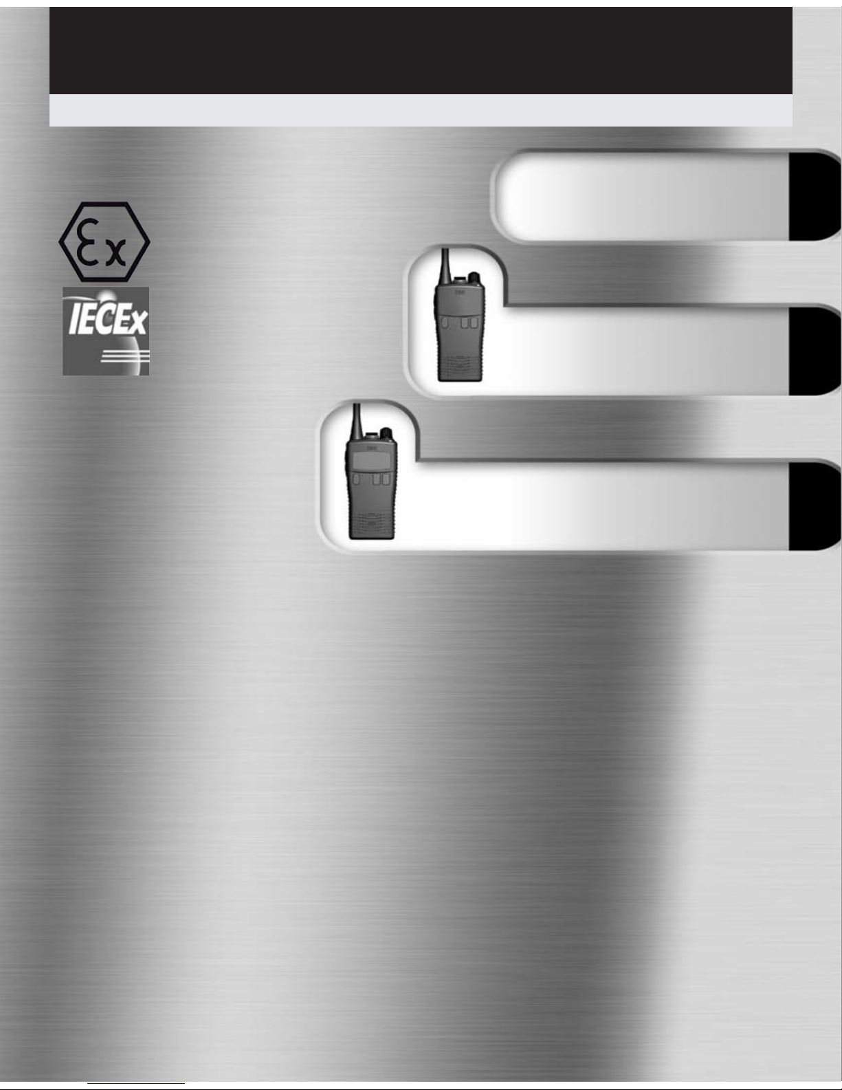
HT952
Entry
User Guide – HT950 Series
v10/10
Common Information
(all models)
HT953
LCD
Professional submersible PMR446 handheld transceivers
II 2 G Ex ib IIC T4
ATEX approved Intrinsically Safe
Ex ib IIC T4
Page 2

Introduction
This guide covers the ‘basics’ of your radio’s operation. To meet your exact
requirements the radio may have been customised by your Entel authorised dealer.
These features will be explained in a separate guide issued by the dealer.
1
Table of Contents
Common Information Page
Certification 2
Radio Care 3
Battery Care 4
Packing List 5
Optional Accessories 5
Preparing Your Radio For Use 6 & 7
Using Your Radio 8 & 9
HT952
Feature List 10
Controls & Indicators 11
Programming Your Radio 12 & 13
Cloning Your Radio 14
Frequency & Tone Table 15 & 16
HT953
Feature List 18
Controls & Indicators 19
LCD Indicators 20
Programming Your Radio 21
Cloning Your Radio 22
Default Channel Configuration 23
Troubleshooting Guide 24
Certification Information 25
Common
Page 3
2
Certification
Declaration of Conformity
We Entel UK Limited of:
Entel UK Ltd
320 Centennial Avenue
Centennial Park
Elstree
Borehamwood
Hertfordshire
WD6 3TJ
United Kingdom
Declares under our sole responsibility that the product range:
HT95X Series Handheld Radio Transceiver
Conforms to the following standards or other nominative documents:
• EN 300 086-2 V1.2.1, EN 301 489-1 V1.8.1:2008, EN 301 489-5 V1.3.1:2002,
EN 60950-1:2006, in accordance with Directive 99/5/EC.
• EN 60079-0:2006, EN 60079-0:2009, EN 60079-11:2007 in accordance with Directive
94/9/EC
Related Certificate:
94/9/EC: Sira 10ATEX2066X Marking: II 2 G Ex ib IIC T4 Gb
IECEx SIR 10.0035X
Notified Body No. 0518
Sira Certification, Rake Lane, Chester CH4 9JN, UK
Quality Assurance Notification:
94/9/EC Intertek Notified Body 0359
Intertek House, Leatherhead KT22 7SB, UK
M Austin
Quality Manager
Common
1 October 2010
Date:
Page 4

3
Radio Care
Common
Warranty
The HT95X comes with a 24 month warranty, for
details see our full terms & conditions.
Advice
• Do not use options or accessories not specified by
Entel
• Ensure that the radio is used within the parameters
for which it was designed
• Please switch the transceiver off before connecting
optional accessories
Warning
Turn the transceiver off in the following locations outside
of the radio’s ATEX approval rating:
• In explosive atmospheres (flammable gas, dust
including metallic & grain powders etc)
• Whilst taking on fuel or while parked near fuel
station
• Near explosives or blasting sites
• In aircraft, medical institutions or near persons
known to be wearing a pacemaker
Caution
• Do not disassemble or modify the transceiver for
any reason
• Do not transmit while touching the antenna
terminal or any exposed metallic parts of the
aerial as this may result in a burn
• Please check and observe regulations in your
country with regards to use whilst driving
End of Life Disposal
• When your Entel transceiver reaches the end of its
useful life, please ensure that the unit is disposed of
in an environmentally friendly way. For country
specific information please see:
www.entel.co.uk/recycling
Cleaning your Radio
After exposure to any potentially corrosive substance
including salt water it is recommended to thoroughly
wash the transceiver in fresh water. If washing with the
battery removed from the radio, ensure that the battery
is not immersed in
water & clean only
with a damp cloth.
Note: Do not
wash the
transceiver if you
suspect the
waterproofing seal
may be damaged.
Please return to
your supplier for
inspection / repair.
Battery care
Introduction
Your Entel radio is supplied with a high performance
Lithium Ion (Li-Ion) battery. These batteries:
• Extend talk time
• Reduce the battery’s size and weight
• Do not suffer from ‘memory effect’ that reduces the
life of Ni-Cad and NiMH batteries
• Have a low toxicity, therefore reducing the impact
on the environment
Battery Pack Precautions
• Switch the transceiver OFF before charging
• Charge the battery pack before use
• Do not recharge the battery pack if it is already fully
charged. This could lead to a premature battery
replacement warning message (See Battery
Communications on page 4)
• Charge the battery in accordance with the
instructions enclosed with your charger
• Do not charge the transceiver and/or battery pack
if they are wet
The battery pack includes potentially hazardous
components. Please:
• Do not disassemble or reconstruct battery
• Do not short-circuit the battery
• Do not incinerate or apply heat to the battery
Page 5
4
Battery Care / Information
• Do not immerse the battery unless attached securly
to the radio in water or get it wet by other means
• Do not charge the battery near fires or under
direct sunlight
• Use only the specified charger and observe
charging requirements
• Do not pierce the battery with any object or
strike it with an instrument
• Do not use the battery pack if it is damaged in any
way
• Do not reverse-charge or reverse-connect the
battery
• Do not touch a ruptured or leaking battery
If liquids from the battery get into your
eyes, immediately:
• Wash your eyes out with fresh water avoiding
rubbing them. Seek medical treatment
Battery Pack
• If a battery is not to be used for an extended period
of time (e.g. several months) remove the battery
pack from the equipment and store in a cool and
dry location (around 0°C) part charged. Do not fully
discharge the battery before storage.
• Each charge cycle reduces the battery’s life.
Minimise the number of times you charge your battery especially in hotter environments which further
shortens a battery’s life.
The battery pack has an over-current protection
circuit fitted. When charging a completely discharged
battery i.e. first charge, ensure the battery is
removed from the radio and then re-attached (if
fitted to radio when charging). This will reset the
protection circuitry and ensure normal operation. This
process will need to be repeated if the battery is allowed to completely discharge in the future. In normal
use this is unlikely.
Battery Communications
Each battery used with your radio has a
microprocessor fitted, which logs the number of times
your battery has been charged.
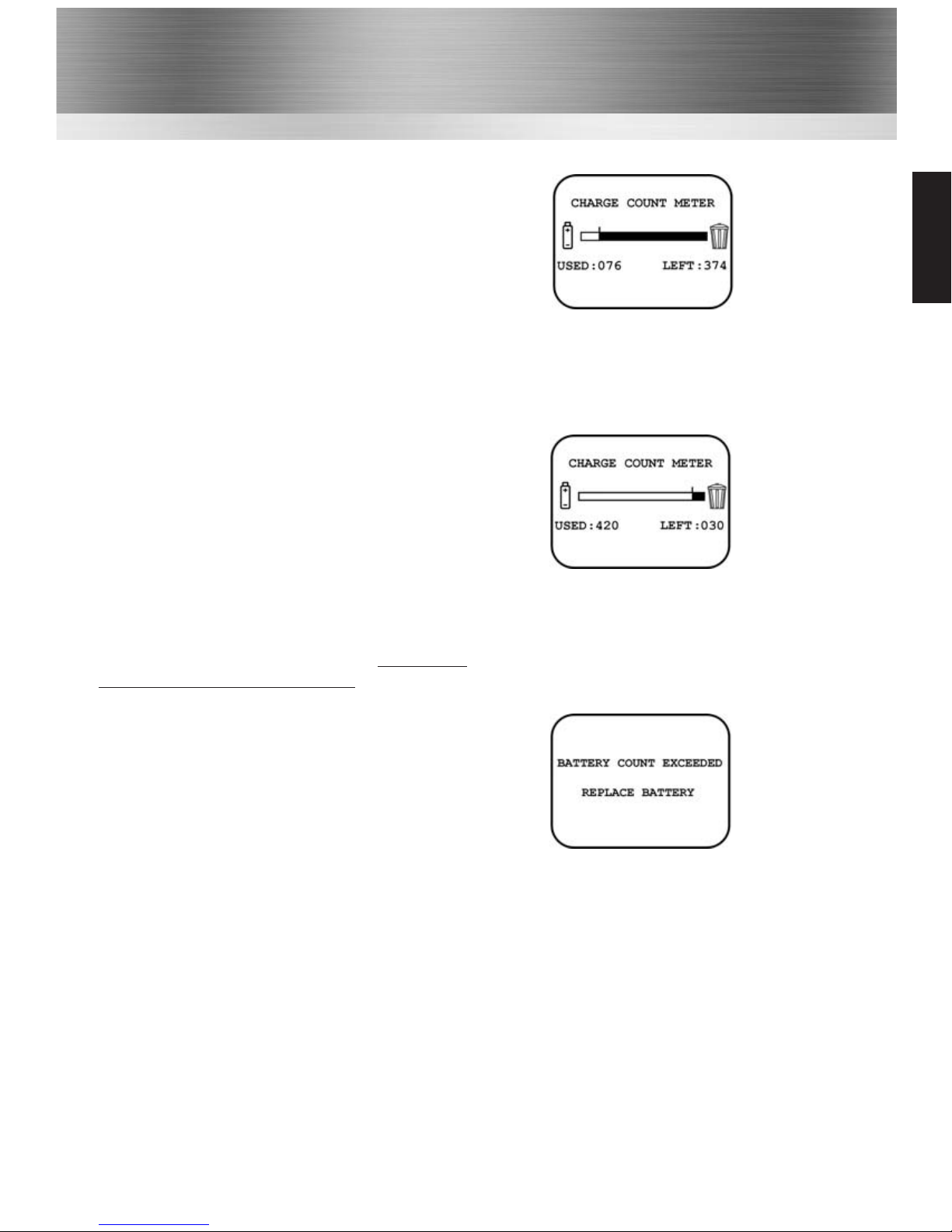
On a radio with an LCD display, the number of times
the battery has been charged, together with the
remaining charge cycles available, will be shown during
switch on (If not de-activated by your dealer).
The warranty on all batteries is 12 months or 450
charge cycles, whichever is the sooner. After 420
cycles, at switch on the radio will emit a series of short
tones, and on LCD models a waste bin icon will flash
to alert you to the need to buy a new battery.
After 450 cycles, at switch on the radio will emit a
series of long beeps, and on LCD models the message
will change to BATTERY COUNT EXCEEDED
REPLACE BATTERY. The radio will continue to
operate but its operational time may be reduced,
eventually failing all together.
Note: only genuine Entel batteries should be used.
Only genuine batteries offer the battery charge count
feature informing you when the battery is reaching the
end of its useful life. Non ATEX batteries will not work
on ATEX radios ensuring customer safety.
Customer satisfaction is assured as you can not be
supplied with sub standard, potentially dangerous
battery packs from 3rd party manufacturers, ensuring
it delivers the expected capacity and endurance.
On HT series batteries a breathable membrane is used.
This is clearly marked on the battery label.
Piercing the membrane will allow water ingress to the
battery and will invalidate the warranty.
Common
Page 6

Optional Accessories
Packing List
• HT95X Radio
• CNB950E Rechargeable 1800mAh Li-Ion battery
• CBH750 Spring loaded belt clip
• CSAHT Intelligent rapid charger
• User guide CD
5
Battery & Charger Options
CNB950E Spare ATEX approved 1800mAh Lithium-Ion battery pack with rear clip
CSAHT 1-way intelligent rapid charger, 110-230v
CSBHT 6-way intelligent, rapid charger, 110-230v
CCAHT-230 1-way trickle charger with 230V mains adapter
CCAHT-110 1-way trickle charger with 110V mains adapter
CCAHT-12 1-way trickle charger with cigar lighter lead, 12V DC operation
Carry Options
CLC952 Heavy duty black leather case with strap & belt loop
CLC953 Heavy duty black leather case with strap & belt loop
CBH750 Spare spring loaded belt clip
Audio Accessory Options
CMP950 Heavy duty submersible speaker microphone
EHP9 D-shaped earpiece (plugs into CMP950 above)
EA12/950 D-shaped earpiece with in-line PTT/microphone & VOX*
EA15/950 Earpiece microphone with transparent acoustic tube & VOX*
EA19/950 D-shaped earpiece with boom microphone and in-line PTT & VOX*
EHP950 D-Shaped earpiece (connects directly to radio)
EPT40/950 Bone conductive earpiece microphone with PTT and VOX*
CHP950HS Single earpiece heavy duty ear defender headset with boom mic for hard hat & VOX*
Note: The use of non Entel approved accessories will invalidate your ATEX intrinsically
safe approval. Refer to certificate Sira 10ATEX 2066X for permitted accessories.
Common
Page 7
Optional Accessories cont...
6
Preparing Your Radio For Use
CHP950HD Double earpiece defender headset with boom mic and in line PTT for hard hat & VOX*
CHP950D Double earpiece headband defender headset with boom mic and in line PTT & VOX*
CHP950BT Bluetooth double earpiece headband defender headset with boom mic and ear cup PTT
* VOX = Voice Operated Transmit (hands free operation)
Bluetooth option board in radio is required to use Bluetooth audio accessories.
For complete up to date list of optional
accessories visit www.entel.co.uk
Common
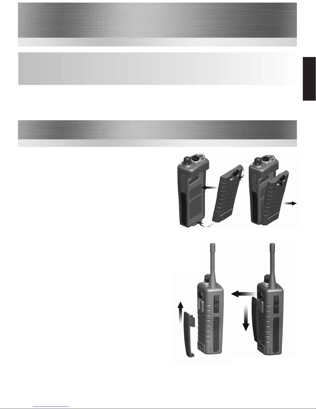
Attaching / Removing the Battery Pack
1 To attach, locate the pegs on the bottom of the
battery and place into the slots on the radio. Then
press the top of the battery against the radio. Secure
battery by tightening the screw clockwise by hand.
(Do not over tighten)
2 To remove, unscrew the locking screw anticlockwise
and pull the battery away from the top of the radio.
1
2
1
2
a
b
Attaching / Removing the Belt Clip
1 To attach, press the clip into the slot on the back
of the battery and slide up until you hear a “click”.
2 To remove, pull the tab (a) towards the belt clip.
Then slide the belt clip downwards (b).
Page 8
7
Preparing Your Radio For Use cont...
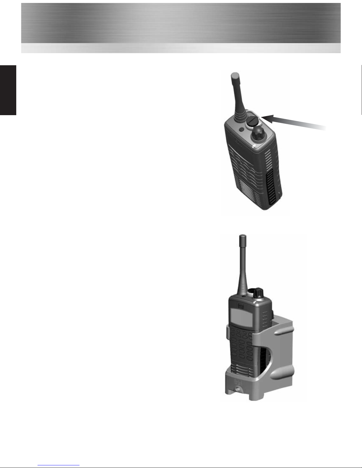
Attaching / Removing Audio Accessories
1
To attach / remove the accessory cover by unscrewing the
locking screw anti-clockwise (leave cover attached or
store in a safe place). Attach accessory plug by locating
over the socket. Carefully tighten the locking screw
clockwise until finger tight (do not tighten with a
screwdriver etc).
2
To remove, unscrew the locking screw by hand in an
anti-clockwise direction (carefully use a coin or
screwdriver if too tight). Ensure you re-fit the accessory
cover so as to protect the socket.
Charging Your Radio
Several charger options are available. Please refer to your
charger user guide.
Common
Page 9

8
Using Your Radio
Turning Your Radio On
Turn your radio on using the on / off volume control on the top of the radio. The radio will “beep”
and the LED will briefly illuminate yellow (the beep may be disabled, if required, by your Entel approved dealer).
Making a Call
Before transmitting on your radio, first ensure that the channel is not in use (yellow or green busy LED
will be illuminated and audio may be heard from speaker). To transmit press and hold the PTT button
on the side of the radio and speak clearly 25-50mm from the microphone.
Release the button to receive.
Transmit Time Out Timer (T.O.T.)
A transmit time out timer is enabled on your radio. This will prevent the radio from transmitting continuously. The maximum transmit duration is set to 90 seconds. If the transmit button is pressed for
this duration, the radio will generate an alert tone 10 seconds before automatically ending the transmission, when a continuous tone will be emitted (the T.O.T. duration is dealer adjustable).
Button Key Beeps
The radio will emit a short confirmation beep when pressing any of the function buttons. This
confidence tone confirms the button has been correctly pressed (key beeps may be disabled by your
dealer).
Channel Monitor Button (Dealer Programmable Function)
Tone/squelch defeat disables both CTCSS and DCS tones used and opens the squelch on the radio.
This will allow you to monitor any transmissions taking place that are not on the same CTCSS/DCS
tone on the channel you have selected and listen to any weak signals that may be breaking up. When
activated, you will hear either a rushing noise or any other channel users.
Low Battery Warning
Alerts you when the battery needs to be recharged. A ‘beep-beep’ audible alert every 20
seconds and flashing red LED will indicate the battery is towards the end of its duty cycle and needs to
be charged (see battery care on page 4 for information on battery life warning alerts).
Panic Alarm Siren
The radio has a local panic alarm button, which, when pressed, will emit a loud piercing siren from the
radio’s loudspeaker. To operate the local panic alarm, press the orange function button on top of the
radio for a minimum of 2 seconds. To cancel the alarm, simply turn the radio off.
Button Lock (Dealer Programmable Function)
A button lock feature is available to lock the channel control and other side / top function
button modes (except panic alarm). If available, press the assigned button to turn button lock on / off.
If a long button press is used to enable button lock, when unlocking, an error tone will be heard until
the button lock disables.
Common
Page 10

9
Using Your Radio cont...
Voice Scrambler (Option)
With the optional voice scrambler you can prevent potential eavesdropping on your radio calls by
others. This will make your voice transmission difficult to understand by anyone monitoring the
same channel that you are using. If your dealer has made this a selectable feature, follow the
instructions provided by the dealer.
* Due to local regulation, in some countries the scrambler feature may not be available, please
check with your dealer prior to purchase.
CTCSS / DCS
This is used to reduce interference from other users on a shared two-way radio communications
channel. Where more than one user group is on the same channel, CTCSS or DCS can be used to
filter out other users. This means you will only hear calls from your group of radios. If the channel
you are using is in use by another user on a different tone, the yellow LED will illuminate on your
radio (indicating the channel is in use). Do not transmit while the channel is busy as both
transmissions will distort.
VOX - Automatic Voice Activation (Dealer Programmable Function)
In VOX mode the radio will react to your voice and transmit automatically without having to press
the PTT button. This is available using the radio without an audio accessory, or with a VOX
compatible accessory.
There is always a slight delay for the electronic switching, therefore starting a transmission with a
lengthy exaggerated or, throwaway, first word is recommended e.g. "H-e-l-l-o Charlie One do you
receive, over".
To enable / disable the VOX feature, press the bottom side function button below the PTT button
for 1 second.
For a list of VOX compatible audio accessories see page 5 of this guide,
contact your dealer or visit www.entel.co.uk
Nuisance Channel Delete (Dealer Programmable Function)
Allows you to remove an interfering channel that you do not want to be part of the channel scan
list. You can remove it by pressing the dealer assigned button when the interfering signal is being
received. Switching the radio off, then on, will reset the radio to its default setting.
Channel Scan (Dealer Programmable Function)
Scanning allows you to efficiently monitor radio activity. When scanning, the tranceiver checks for
a signal on each channel and will only stop if a signal is present.
HT952 - To start / stop scanning, press the dealer assigned function button.
HT953 - Turn the channel control to the scan channel assigned by your dealer.
The yellow LED will rapidly flash to indicate the radio is scanning. When a valid signal is detected,
the radio will stop scanning and monitor the transmission. At the end of the transmission the radio
will remain on the channel for 5 seconds allowing you to reply to the call if desired. If you do not
reply within this time, the radio will automatically resume scanning.
Common
Page 11
10
Standard Features:
• Up to 16 programmable channel positions
• Transmit power output 0.5 Watts
• CTCSS & DCS (Analogue & Digital squelch) with squelch tail elimination (removes the ‘shh’ noise)
• Exceptionally loud and clear audio
• Robust design, exceeds MIL-STD-810C/D/E/F
• Environmentally protected to IP68 i.e. submersible to 5 metres for up to 60 minutes
• 1800mAH Lithium-Ion battery for superior operational time
• Automatic power save to further increase operational time
• Low battery alert indicates when the battery needs recharging via a warning bleep and a slowly
flashing red LED
Dealer Programmable Features:
• VOX for hands free operation (with suitable audio accessory)
• Channel scanning
• Panic (personal attack) button causes high pitch, high volume, siren tone to be emitted from the
radio’s speaker
• Voice scrambler
• Key lock button
• Prefixed minimum volume level and fixed bleep level
• Channel monitor (CTCSS/DCS Defeat)
HT952
HT952
Page 12
11
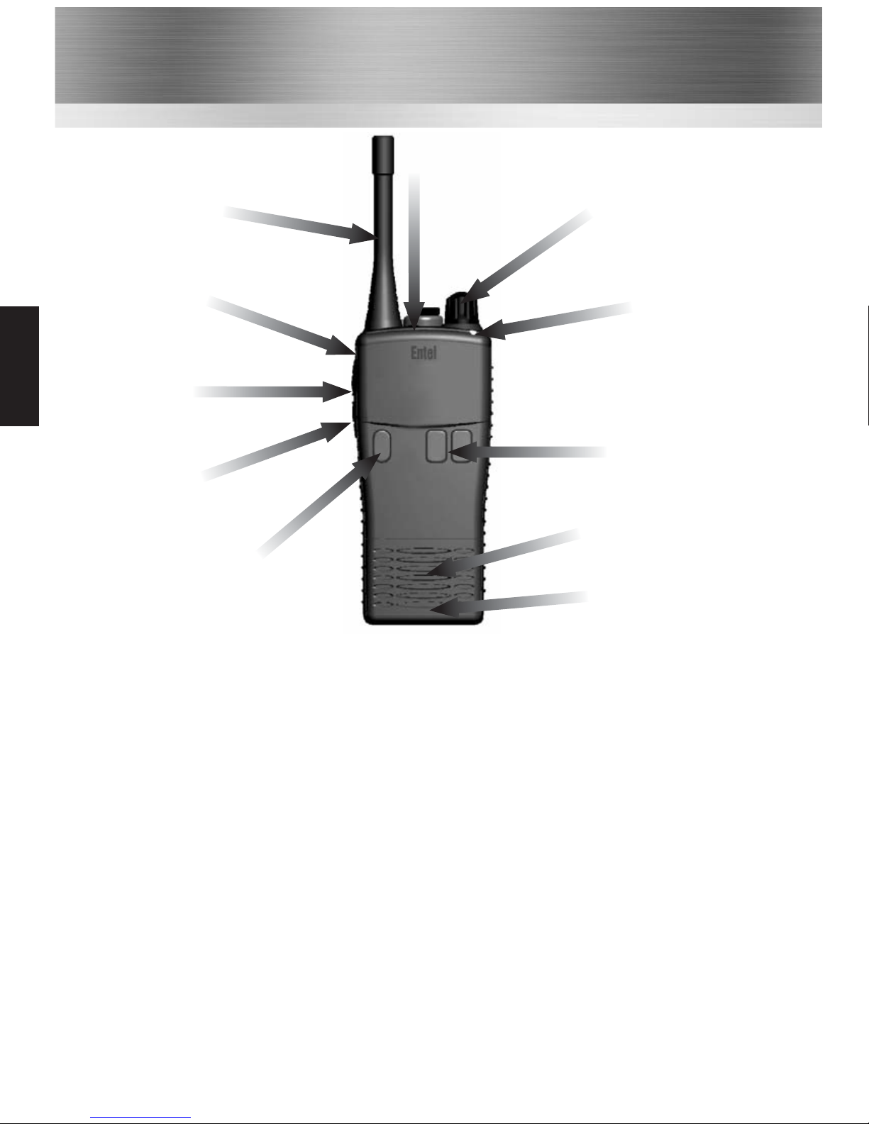
Controls & Indicators
3
Channel / Scan control
Antenna
5
Dealer
programmable
button 1
4
Push To Talk
(PTT) button
6
Dealer
programmable
button 2
1
On / Off
2
Volume control
Speaker
Microphone
1
On / Off button. Press to turn radio on, press and hold to turn off.
2
Press up / down buttons to increase / reduce volume.
3
Channel / Scan control. Rotate to select the desired channel or scan setting.
4
Push To Talk (PTT) button. Press to speak and release to listen.
5
Dealer programmable button 1 (ask your dealer for more information).
6
Dealer programmable button 2 (ask your dealer for more information).
7
Dealer programmable button 3 and LED indicator. Default - Local panic alarm long button press.
8 LED indicator.
• RED steady = Transmitting
• RED flashing slowly = Battery needs re-charging
• GREEN steady = Receiving
• YELLOW steady = Non valid signal detected
• YELLOW flashing rapidly = Scanning
7
Dealer
programmable
button 3
8
LED indicator
HT952
Page 13
12
Programming your HT952 radio
Checking the current configuration
• A momentary press of the top side function
button will cause the radio to beep the
frequency programmed into the channel
(see Frequency Table beep codes on P.15).
Changing the assigned frequency
• Press and hold the PTT button and the top
side function button together until the
radio emits a “warble” sound and
illuminates the LED red, confirming the
radio is in channel programming mode.
• Using the upper side function button enter
the frequency number from the table. For
example to enter frequency number 7 press
the upper button 7 times. There are 8
frequencies available in total (see Frequency
Table on P.15).
Now press the PTT button to store the setting
and automatically return to the “check
configuration” mode (a long beep and flashing
yellow LED will confirm this action).
To check the entered setting, press the top side
function button.
Note: If you accidentally “go past” the required
frequency number, keep pressing the button until
you hear the “warble” sound again (emitted on
button press 9). This confirms you are back at the
start of the channel assigned frequency mode.
Please note: The orange button allows you to
escape from any setting without saving the data.
If you are in frequency programming mode but
decide not to save the setting you may press
the orange button to exit without saving.
Check / Modify the Frequency
The radio’s frequency and tone configuration can be changed in user programming mode. This will
allow you to put any of the standard frequencies or tones in to any channel position. When a radio
has been configured this information can be quickly and easily cloned into other units using an
optional cloning cable. The programming process is confirmed using a series of audible beep tone
patterns.
To put radio in to user programming mode
• To put the radio in to user programming
mode, press and hold the top side function
button and PTT button and turn the radio
on
• The radio will emit a beep and
the LED slowly flash yellow to confirm “user
programming mode” has been entered.
• Select the channel to be checked /
modified.
HT952
Page 14
13
Check / Modify CTCSS/DCS Tone
Checking the current configuration
• A momentary press of the bottom side
function button will cause the radio to beep
the CTCSS/DCS tone programmed into the
channel (see CTCSS/DCS beep codes
below). If no tone is programmed in to a
channel position a tone will
sound.
Changing the assigned CTCSS/DCS Tone
• Press and hold the PTT button and the
bottom side button together until the radio
emits a “warble” sound and illuminates the
LED GREEN, confirming the radio is in
CTCSS/DCS programming mode.
• Using the two side buttons enter the
CTCSS/DCS number from the table below.
• The lower side button = 10’s of units (radio
emits a sound on every increment)The
upper side button = units (radio emits a
short sound on every increment).
• For example to enter CTCSS tone 189.9Hz
(number 38) press the lower button three
times to enter the 10’s (3) and the upper
side button eight times to enter the units
(8).
• Now press the PTT button to store the
setting and automatically return to the
“check configuration” mode (a sound
and flashing yellow LED will confirm this
action).
To check the entered setting, press the
bottom side function button.
• To turn off CTCSS/DCS tone on a channel,
enter tone programming mode, press the PTT
button without selecting a tone.
•
Once you have finished programming the
radio press the orange button on top of the
radio to exit programming mode and return
the radio to normal operation.
Please note: The orange button allows you to
escape from any setting without saving the data.
If you are in frequency programming mode but
decide not to save the setting you may press
the orange button to exit without saving.
Special notes re DCS tones
If you have entered a DCS tone and pressed
the PTT button during programming you will
immediately hear a sound prompting you
to set the tone to “inverted” or “normal”.
Press the upper side button to select normal or
inverted DCS tone.
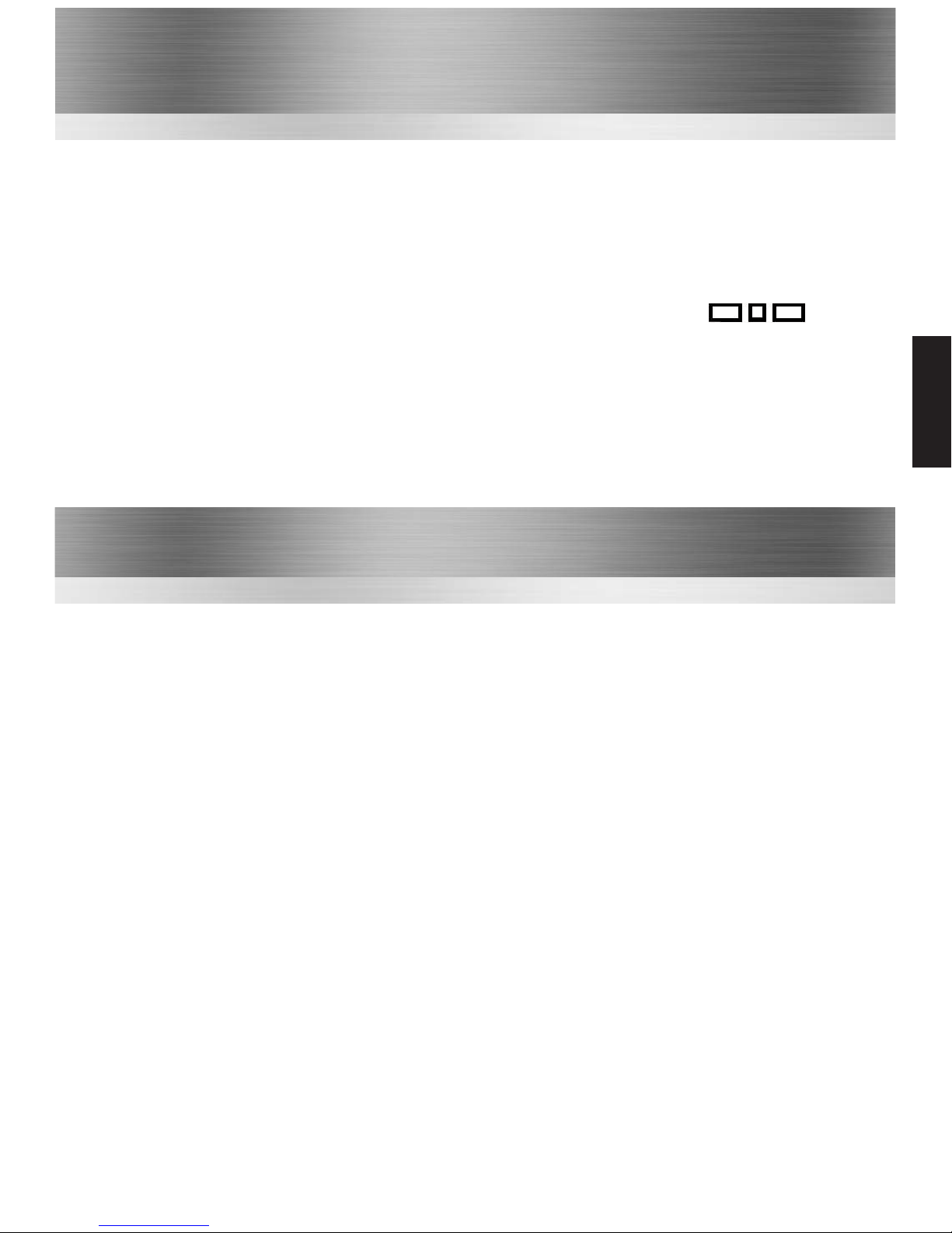
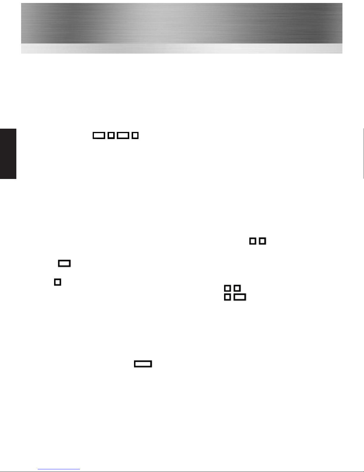
Normal =
Inverted =
Now press the PTT button to store the setting.
A long beep and flashing yellow LED will
confirm safe storage.
To check the entered setting, press the bottom
side function button.
HT952
Page 15

Radio cloning allows you to copy the programmed channel and button setup information from a
‘master’ radio into other unprogrammed radios without the use of a PC. Cloning is performed
by connecting two radios together using a HTCL cloning lead.
How to clone a radio
Connect the HTCL lead to the accessory socket on both radios. Ensure the master radio is
powered up before the slave radio.
1. Master Radio (sending radio)
Put the radio you will be using to programme other radios into ‘clone send’ mode by pressing
the PTT and bottom side function buttons at the same time and turn the power on. The radio
will emit a alert and the LED will alternately flash yellow / red.
2. Slave Radio (receiving radio)
Put the radio you wish to programme into ‘clone receive’ mode by pressing the two side
function buttons at the same time and turn the power on. The radio will emit a short “beep”
and the LED will alternately flash yellow / green.
Transferring data
Master radio Press the PTT switch on the radio. A short beep will be emitted to confirm
the process has been initiated.
The radio’s LED will flash red whilst data transfer is in progress. Once all the
data has successfully transfered the LED will flash yellow/red.
Slave radio
The radio’s LED will flash green whilst data transfer is in progress.
Once all the data has successfully transferred the LED will flash yellow/green.
To return the radio to normal mode switch the radio off then on again.
The ‘master’ radio will automatically return to ‘clone send’ mode indicated by the LED
alternately flashing yellow / red. You may now either programme another radio or press the orange button to return the ‘master’ radio to normal.
To return to clone send mode if an error occurs, press the orange button on top of the ‘master
radio’. A alert will be emitted and the radio’s LED alternately flash yellow / red).
14
Radio Cloning HT952
HT952
Page 16
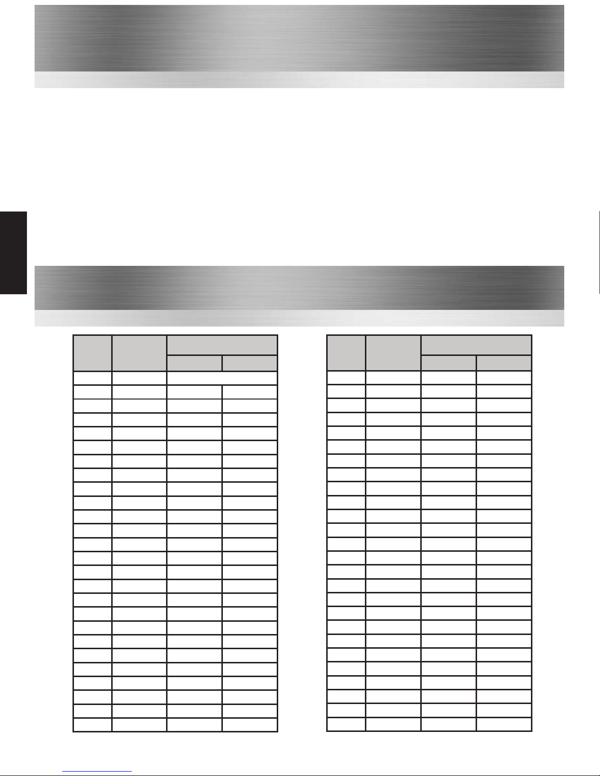
Frequency Table
No Frequency Beeps
1 446.00625 MHz •
2 446.01875 MHz • •
3 446.03125 MHz • • •
4 446.04375 MHz • • • •
5 446.05625 MHz • • • • •
6 446.06875 MHz • • • • • •
7 446.08125 MHz • • • • • • •
8 446.09375 MHz • • • • • • • •
CTCSS (PL) Tone Table
Ref
CTCSS
(Hz)
Beeps
▬
●
0 0
See p13 Check configuration
1 62.5 - 1
2 67 - 2
3 69.3 - 3
4 71.9 - 4
5 74.4 - 5
6 77 - 6
7 79.7 - 7
8 82.5 - 8
9 85.4 - 9
10 88.5 1 0
11 91.5 1 1
12 94.8 1 2
13 97.4 1 3
14 100 1 4
15 103.5 1 5
16 107.2 1 6
17 110.9 1 7
18 114.8 1 8
19 118.8 1 9
20 123 2 0
21 127.3 2 1
22 131.8 2 2
23 136.5 2 3
24 141.3 2 4
25 146.2 2 5
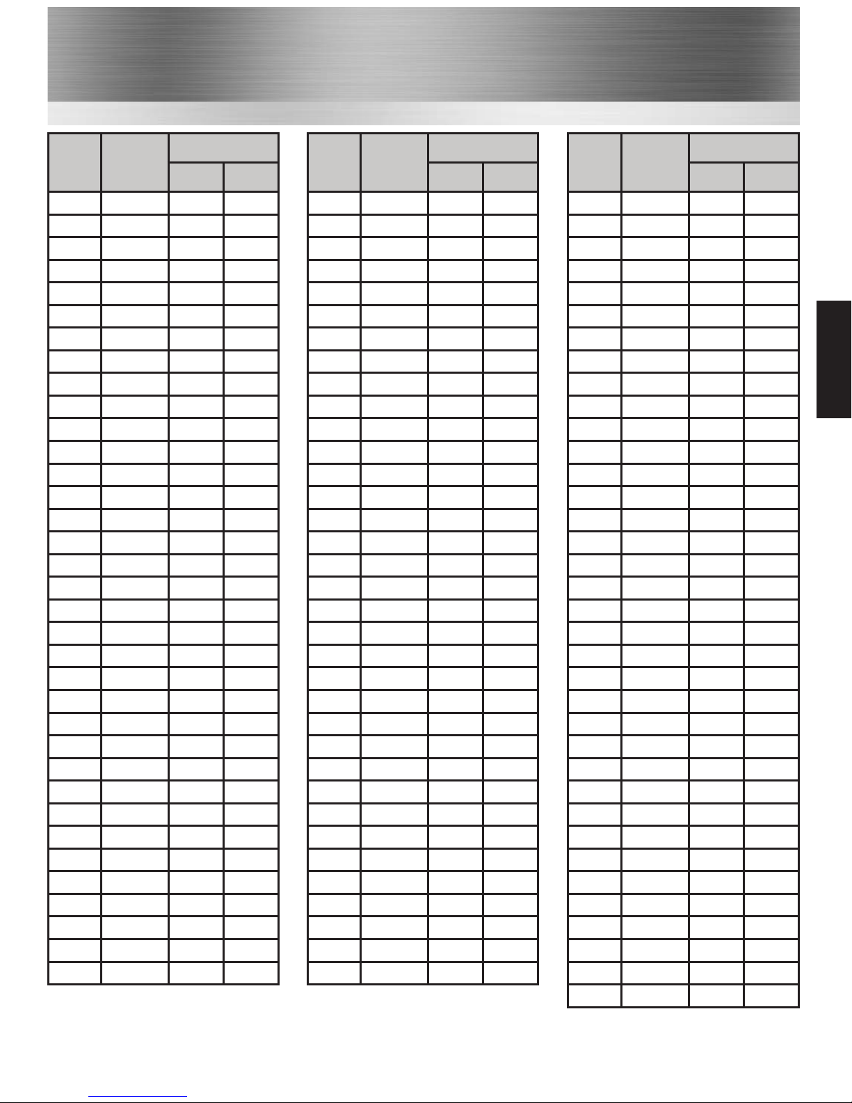
Ref
CTCSS
(Hz)
Beeps
▬
●
26 151.4 2 6
27 156.7 2 7
28 159.8 2 8
29 162.2 2 9
30 165.5 3 0
31 167.9 3 1
32 171.3 3 2
33 173.8 3 3
34 177.3 3 4
35 179.9 3 5
36 183.5 3 6
37 186.2 3 7
38 189.9 3 8
39 192.8 3 9
40 196.6 4 0
41 199.5 4 1
42 203.5 4 2
43 206.5 4 3
44 210.7 4 4
45 218.1 4 5
46 225.7 4 6
47 229.1 4 7
48 233.6 4 8
49 241.8 4 9
50 250.3 5 0
51 254.1 5 1
15
HT952
Page 17
16
DCS (DPL) Tone Table
Ref DCS
Beeps
▬ ●
52 023 5 2
53 025 5 3
54 026 5 4
55 031 5 5
56 032 5 6
57 043 5 7
58 047 5 8
59 051 5 9
60 054 6 0
61 065 6 1
62 071 6 2
63 072 6 3
64 073 6 4
65 074 6 5
66 114 6 6
67 115 6 7
68 116 6 8
69 125 6 9
70 131 7 0
71 132 7 1
72 134 7 2
73 143 7 3
74 152 7 4
75 155 7 5
76 156 7 6
77 162 7 7
78 165 7 8
79 172 7 9
80 174 8 0
81 205 8 1
82 223 8 2
83 226 8 3
84 243 8 4
85 244 8 5
86 245 8 6
Ref DCS
Beeps
▬ ●
94 315 9 4
95 331 9 5
96 343 9 6
97 346 9 7
98 351 9 8
99 364 9 9
100 365 10 0
101 371 10 1
102 411 10 2
103 412 10 3
104 413 10 4
105 423 10 5
106 431 10 6
107 432 10 7
108 445 10 8
109 464 10 9
110 465 11 0
111 466 11 1
112 503 11 2
113 506 11 3
114 516 11 4
115 532 11 5
116 546 11 6
117 565 11 7
118 606 11 8
119 612 11 9
120 624 12 0
121 627 12 1
87 251 8 7
88 261 8 8
89 263 8 9
90 265 9 0
91 271 9 1
92 306 9 2
93 311 9 3
Ref DCS
Beeps
▬ ●
122 631 12 2
123 632 12 3
124 654 12 4
125 662 12 5
126 664 12 6
127 703 12 7
128 712 12 8
129 723 12 9
130 731 13 0
131 732 13 1
132 734 13 2
133 743 13 3
134 754 13 4
135 036 13 5
136 053 13 6
137 122 13 7
138 145 13 8
139 212 13 9
140 225 14 0
141 246 14 1
142 252 14 2
143 255 14 3
144 266 14 4
145 274 14 5
146 325 14 6
147 332 14 7
148 356 14 8
149 446 14 9
150 452 15 0
151 454 15 1
152 455 15 2
153 462 15 3
154 523 15 4
155 525 15 5
156 526 15 6
157 645 15 7
HT952
Page 18

17
Intentionally Left
Blank
Page 19
18
All the features of the HT952 (see page 10) plus the following:
Standard Features:
• LCD Display
• Up to 255 programmable channel positions (8 RF channels)
• Low battery indication on LCD dispaly
• Battery count is displayed at switch on
• Multiple channel scan groups
HT953
HT953
Page 20
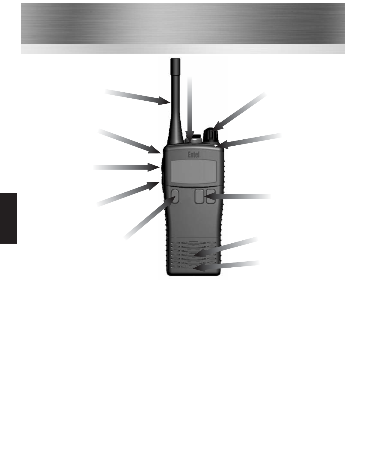
Controls & Indicators
1
On / Off button. Press to turn radio on, press and hold to turn off.
2
Press up / down buttons to change channel (this can be dealer configured to be volume control).
3
Rotate to select the desired volume. (this can be dealer configured to be channel/scan control).
4
Push To Talk (PTT) button. Press to speak and release to listen.
5
Dealer programmable button 1 (ask your dealer for more information).
6
Dealer programmable button 2 (ask your dealer for more information).
7
Dealer programmable button 3 and LED indicator. Default - Local panic alarm long button press.
8 LED indicator.
• RED steady = Transmitting
• RED flashing slowly = Battery needs re-charging
• GREEN steady = Receiving
• YELLOW steady = Non valid signal detected
• YELLOW flashing rapidly = Scanning
Antenna
5
Dealer
programmable
button 1
4
Push To Talk
(PTT) button
6
Dealer
programmable
button 2
1
On / Off
2
Channel / Scan
control
Speaker
Microphone
7
Dealer
programmable
button 3
3 Volume control
8 LED indicator
19
HT953
Page 21
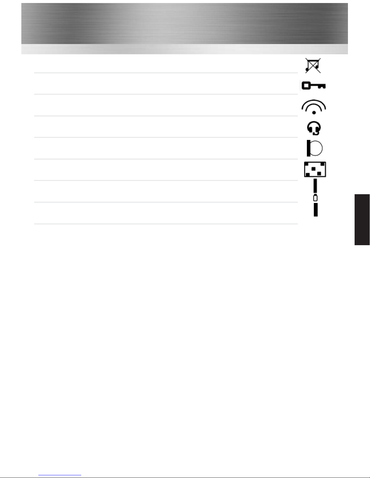
• Key Bleeps Off
• Keypad Locked
• Bluetooth device connected
• Accessory Connected
• VOX Enabled
• Scramble Enabled
• Battery State
• Receive strength
LCD Indicators
RX
20
HT953
Page 22
21
Programming your HT953 radio
The radio’s frequency and tone configuration can be changed in user programming mode. This
will allow you to put any of the standard frequencies or tones in to any channel position. When a
radio has been configured this information can be quickly and easily cloned into other units using
an optional cloning cable.
Checking the current configuration
• The display will show the selected channel,
the PL/DPL tone and the frequency.
Changing the assigned frequency
• Press the top side function button to
highlight the frequency field. Turn top rotary
control to change the frequency. Press PTT
button to save the selection. Frequency
table is on P.15).
Changing the assigned tone
• Press the top side function button to
highlight the tone field. Turn top rotary
control to change the tone. Press PTT
button to save the selection. (Pressing the
lower side function button whilst turning the
rotary control will change the selection in
increments of 10.)
Check / Modify the Frequency/Tone
To put radio into user programming mode
• To put the radio into user programming
mode, press and hold the top side function
button and PTT button and turn the radio
on.
• The radio will emit a beep to
confirm “user programming mode” has
been entered.
HT953
Page 23

The user programmable Key Lock function allows the Key Lock to be assigned to the lower side
button and enabled \ disabled via the radio’s controls without the use of a computer.
Checking The Status Of The Key Lock
To check whether the key lock is currently enabled or disabled:
• Put the radio into User Programming Mode (UPM) by pressing and holding the top side
function button and the PTT button when you turn the radio on. This will cause the radio to
emit a beep and the LCD will display the message “Button Programming Mode”
followed by a menu showing the settings for the radio’s current channel including
either "KL0" meaning the key lock is disabled or "KL1" meaning the key lock is enabled.
Note: If you press the PTT while in User Programming Mode it will emit a beep & save the
settings of the current channel, it will NOT emit beeps for the status of the key lock as in the
entry level models).
Enabling \ Disabling The Key Lock
• Put the radio into User Programming Mode (UPM).
• Enter "Key Lock Button Programming Mode" by pressing and holding the PTT until a
"warble" sound is emitted from the radio and the radio displays the current state of the key
lock.
• To Disable the Key Lock press the upper side button and the radio will emit 2 low tone
beeps to confirm it is disabled and the LCD will display “Key Lock Disable”.
OR
• To Enable the Key Lock press the lower side button and the radio will emit 2 high tones to
confirm it is enabled and the LCD will display “Key Lock Enable”.
To save the setting press the PTT button, the radio will confirm this with a single beep and
return to the User Programming Mode.
Using The User Programmable Key Lock
• If no functions are assigned to the short press of the lower side button, then the key lock will
automatically be assigned to the short press of the lower side button.
• If a function is assigned to the short press of the lower button, but no function is assigned to
the long press of the lower side button, then the key lock will be assigned to the long press
of the lower side button.
• But if functions are assigned to both the short and long press of the lower side buttons, then
the key lock feature cannot be used and if you perform a long press of the lower side button
the radio will emit an error beep and the LCD will display the message "Cannot Override".
Troubleshooting:
If you are having difficulting programming the user programmable feature, check the version of
the firmware is v2031 or above by pressing & holding the PTT during switch on.
22
User Programmable Key Lock
HT953
Page 24
Radio cloning allows you to copy the programmed channel and button setup information from a
‘master’ radio into other unprogrammed radios without the use of a PC. Cloning is performed
by connecting two radios together using a HTCL cloning lead.
How to clone a radio
Connect the HTCL lead to the accessory socket on both radios. Ensure the master radio is
powered up before the slave radio.
Master & Slave Radio
To put the radios into clone mode, press the lower side function button and turn radio on. Radio
will display ‘Programming mode Progress.....’ and LED will flash orange/green.
Transferring data
Master radio Press the top side function button and top orange button together to initiate
data transfer.
Slave radio
The radio’s LED will flash green whilst data transfer is in progress.
Once all the data has successfully transferred the LED will flash orange/green.
To return the radio to normal mode switch the radio off then on again.
The ‘master’ radio will automatically return to ‘clone send’ mode. You may now either
programme another radio or switch radio off then on to return radio to normal.
If an error occurs during data transfer a alert will sound.
23
Radio Cloning HT953
HT953
Page 25

Default Channel Configuration
The HT95X hand portable radio has been factory programmed with the default frequencies in
the table below. This configuration may offer compatibility with other brands of PMR446 radio
but can be altered by your dealer to match any existing PMR446 equipment.
24
Ch. 1 446.006250 CTCSS tone 94.8Hz
Ch. 2 446.018750 CTCSS tone 88.5Hz
Ch. 3 446.031250 CTCSS tone 103.5Hz
Ch. 4 446.043750 CTCSS tone 79.7Hz
Ch. 5 446.056250 CTCSS tone 118.8Hz
Ch. 6 446.068750 CTCSS tone 123Hz
Ch. 7 446.081250 CTCSS tone 127.3Hz
Ch. 8 446.093750 CTCSS tone 85.4Hz
Ch 9 446.006250 CTCSS tone 67Hz
Ch10 446.018750 CTCSS tone 71.9Hz
Ch11 446.031250 CTCSS tone 74.4Hz
Ch12 446.043750 CTCSS tone 77.0Hz
Ch13 446.056250 CTCSS tone 79.7Hz
Ch14 446.068750 CTCSS tone 82.5Hz
Ch15 446.081250 CTCSS tone 85.4Hz
Ch16 446.093750 CTCSS tone 88.5Hz
Below are in HT953 only
Ch17 446.006250 CTCSS tone 110.9Hz
Ch18 446.018750 CTCSS tone 118.8Hz
Ch19 446.031250 CTCSS tone 127.3Hz
Ch20 446.043750 CTCSS tone 136.5Hz
Ch21 446.056250 CTCSS tone 146.2Hz
Ch22 446.068750 CTCSS tone 156.7Hz
Ch23 446.081250 CTCSS tone 167.9Hz
Ch24 446.093750 CTCSS tone 179.9Hz
HT953
Page 26
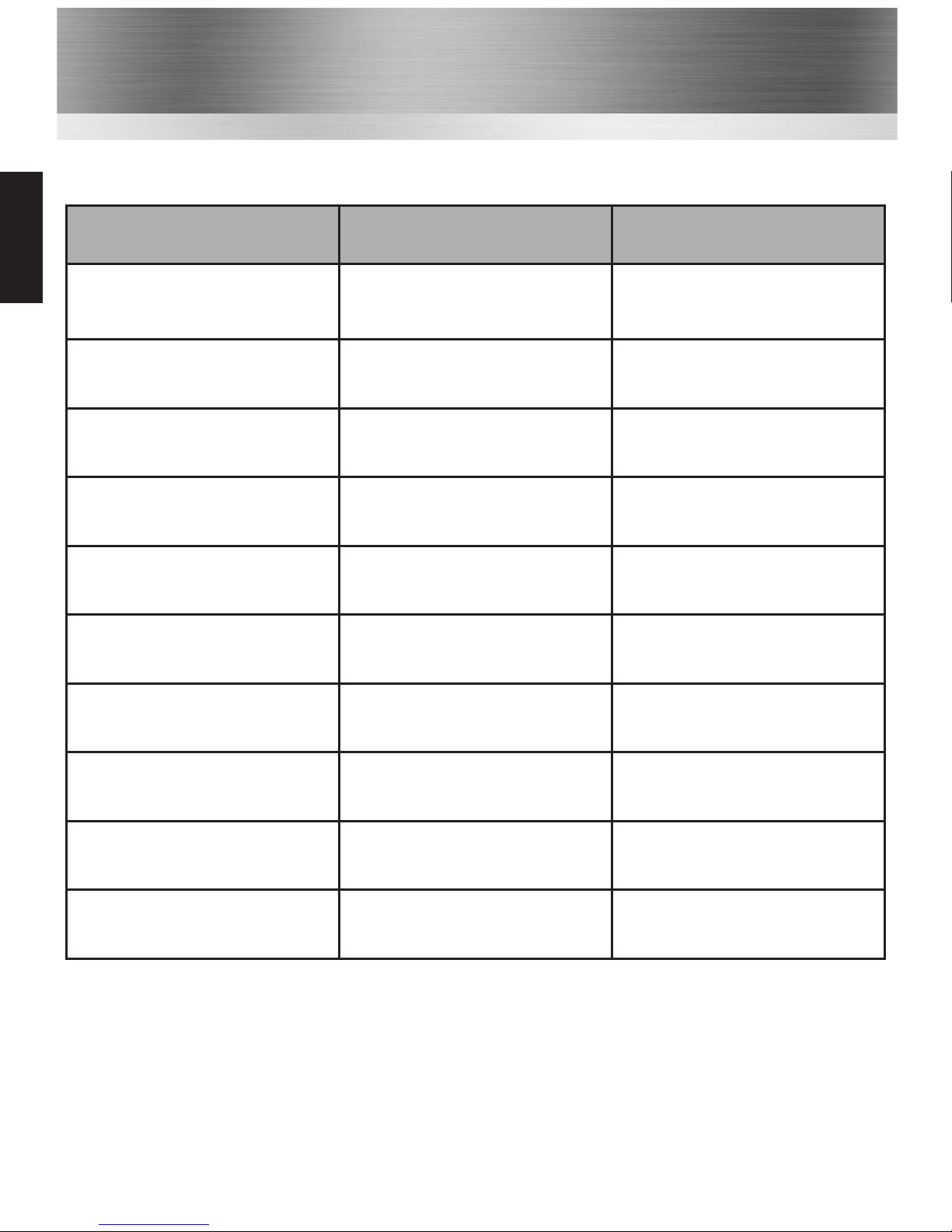
Troubleshooting Guide
PROBLEM PROBABLE CAUSE SOLUTION
Radio will not power on
Battery needs charging
Battery is exhausted
Recharge battery pack
Replace the battery pack
Radio will not talk with others
Radios may be on different channel
or tone code
Check that all radios in same group
are using the same channel and
tone
Hearing others’ conversations
Using same channel and
tone as other users
Select a different channel and tone
Control buttons not functioning Button lock activated Turn button lock off
Radio transmits without pressing
PTT button
VOX has been enabled
Press assigned VOX button to
switch VOX off
Unintelligible audio signal received
or transmitted
Voice scrambler in wrong mode to
other radios
Ensure scrambler either enabled
or disabled to be compatible with
other radios
Accessory does not
work with radio
Accessory plug not seatin
correctly in accessory socket
Incompatible accessory
Check connection to accessory
socket
Replace with genuine accessory
Radio emits constant tone
when switching on
Incompatible battery fitted Replace with genuine Entel battery
Radio emits 5 short beep tones
when switched on
Battery has used almost all
recommended charge cycles
Prepare to replace battery
Radio emits 5 long beep tones
when switched on
Battery has used all recommended
charge cycles
Replace battery
25
Common
Page 27

26
Certification
ATEX approved
Intrinsically Safe
Sira 10ATEX2066X
II 2 G Ex ib IIC T4
Ex ib IIC T4
SAFETY NOTES
• HT Series V2 ATEX radios must always be used within the terms of their certification.
• Keep the radios away from aggressive substances. If used in a hostile environment, extra
protection may be needed.
• To prevent ignition of hazardous atmospheres, batteries must only be charged in an area
known to be non-hazardous.
• Use of battery chargers other than the Entel charger supplied will invalidate the explosion
protection certification.
• No unauthorised repairs are permitted.
• This equipment is designed and manufactured to protect against other hazards as defined in
paragraph 1.2.7 of ATEX Annex II of the Directive 94/9/EC
• Radios fitted with a CNB940E battery pack must not be used outside of the ambient
temperature range Tamb = -20ºC to +28ºC
• Radios fitted with a CNB950E battery pack must not be used outside of the ambient
temperature range indicated on the battery pack label.
Certification
Certification
Page 28

Notes
Use this page to record important information, such as the serial number of your radio, and
channel details.
27
Notes
Page 29
‘the
choice’
professional’s
Headquarters: United Kingdom www.entel.co.uk
Copyright Entel UK Ltd. 2009
Registered Community Design Application 000810890
U.S. Design Patent Pending No. 23/182,829
Copyright and Unregistered Design Right Entel UK 2009
All rights reserved
<Intended Country Of Use>
AT
BE
BG
CY
CZ
DK
EE
FI
FR
DE
GR
HU
IS
IE
IT
LV
LT
LU
MT
NL
NO
PL
PT
RO
SK
SI
ES
SE
CH
UK
 Loading...