

Page 1
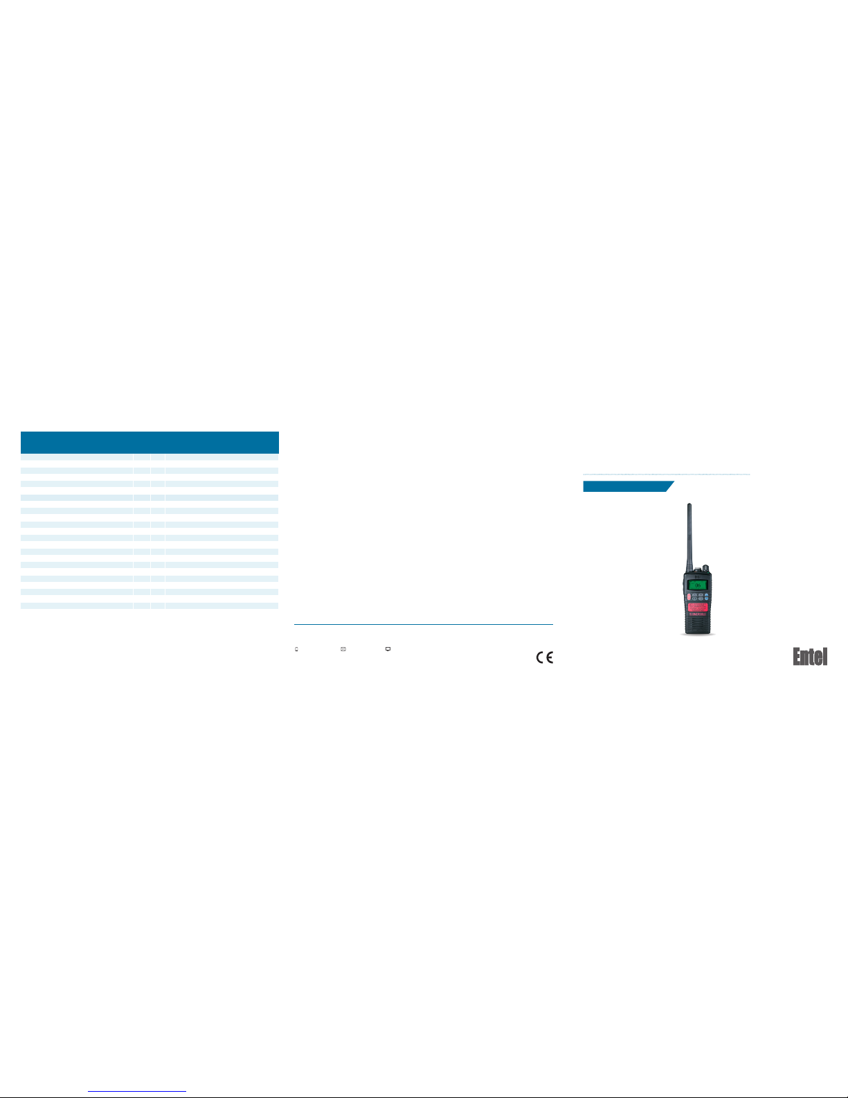
HTx44 Series
HT544 | HT844 | HT944
Quick Start User Guide
Designed in th e United Kingdom
CO NTAC T
For more informat ion about our produc ts please contac t us:
+44 (0)20 8236 00 32 [email protected] entel.co.uk
All Rights Reserved. Copyright Entel UK Ltd.
Model Descri ption ATEX IECEx Permitte d models
CNB550E 1800mAh Li-Ion battery pack
All HT500 Ser ies
CNB950E 1800mAh Li-Ion battery pack
All HT800 V2, HT 900 V2
CMP500 Speaker/microphone
All HT500 Ser ies
CMP950 Speaker/microphone
All HT800 V2, HT 900 V2
CHP950D Ear defender headset
All HT500, HT8 00 V2, HT900 V 2
CHP950HS Ear defender headset
All HT500, HT8 00 V2, HT900 V 2
CHP950HD Ear defender headset
All HT500, HT8 00 V2, HT900 V 2
PTT 951 Push to talk switc h
All HT500, HT8 00 V2, HT900 V 2
PTT950E Push to talk switch
All HT500, HT8 00 V2, HT900 V 2
PTT 951E Push to talk swi tch
All HT500, HT8 00 V2, HT900 V 2
PTT 951C Push to talk switch
All HT500, HT8 00 V2, HT900 V 2
CXR16/950 Throat earphone/microphone
All HT500, HT8 00 V2, HT900 V 2
CXR5/950 Skull earphone/microphone
All HT500, HT8 00 V2, HT900 V 2
EA12/ 950 Earphone/microphone
All HT500, HT8 00 V2, HT900 V 2
EA15/9 50 Earphone/microphone
All HT500, HT8 00 V2, HT900 V 2
EA19/9 50 Earphone/microphone
All HT500, HT8 00 V2, HT900 V 2
EHP950 Earphone
All HT500, HT8 00 V2, HT900 V 2
Savox C-C500 Cert no. VTT 0 6 ATEX 043X
All HT800 V2, HT 900 V2
Savox 100 + Cer t no. VTT 06 ATEX 0 36X
HT981, HT9 81S
Savox 400 Cert no. V TT 05 ATEX 009X
HT981, HT9 81S
Savox, FPS-COM Cert no. ITS08 ATEX25772X
HT981, HT981S, HT983, HT983U, HT983S, HT983SU
SABRE-COM Cert no. ITS03 ATEX21290X
HT981, HT981S, HT983, HT983U, HT983S, HT983SU
FPS-COM-P lus VA R-C Cert no. ITS11ATEX27318X
All HT800 V2, HT 900 V2
The Entel ATEX and IECEx transceiver s should only be used with the specic, per mitted accessories, as deta iled above.
Page 2

PREPARING YOUR RAD IO FOR USE
Attaching/removing the antenna
Attaching / re moving the batter y pack
To atta ch, c arefully align the antenna with the
socket. Screw in the antenna and cloc kwise
(taking care not to cros s the thread) until it
is seated rm ly with th e accessor y cover’s
rubber ring bet ween th e antenna and the top
of the radio (A).
1. To remove, unscrew the antenna
anti-clockwise (B).
1. To attach, locate t he pegs on the bottom o f the
battery into the s lots on the radio and press
the top of the batter y against t he radio. Se cure
battery by tightenin g th e scr ew c lockwise
by ha nd. (Do n ot u se an y imp lement or over
tighte n). (C)
2. To remove, unscrew the locking screw
anti-clock wise and pull the batter y away
from the top of the radio. (D)
A
B
C
D
SWITCHING ON, RECEPTION
AND SWITCHING OFF
1. To switch on, press and hold the on /off
button (1) on the front of the radio.
2. When the ra dio has passe d its di agnos tic te sts,
it will emit a fanfa re tone.
3. The rad io will ente r standby mo de. This is
indicated by the LED Amber ashing once
every 5 seconds, sig naling that the radio is
ready for use.
4. Adjust t he volume cont rol (2) to s elect the
desired volume le vel.
5. Using the channel buttons (3) ensure you have
the correct c hannel selected.
6. When rece iving a valid sign al, the LED will
illuminate steady gre en and audio will be
emitted fr om the radio’s sp eaker or audio
accessory ( if attached).
7. When nished us ing t he rad io, sw itch off
by pres sing an d holdi ng the on/off button
(1) until the radio be eps and the LED/LCD is
extinguished.
TRANSMITTING
1. Perform steps 1 through t o 5 above.
2. Before transmitting, monitor the channel
and make sure it is cl ear.
3. When receiving a s ignal, w ait until the signal
stops before transmitting. The radio c annot
transmit and receive simultaneously.
4. Press the Push To Talk (PT T) b utt on (4 ) to be gi n
your transmission. To conrm transmission the
LED illuminates re d.
5. For best transmitted speech quality, you must
talk dire ctly into the r adio’s micro phone (9) at
around 4cm betwe en your mouth and the ra dio
complete, the ch arger.
6. Please note: if you talk into the top of th e
radio or wi th your mouth further a way, you will
transmit poor quality speech.
7. When the transmission is nished release the
PTT button.
EU DECLARATION OF CONFORMITY
Hereby, Entel UK Limited of:
320 Centennial Ave, C entennial Park,
Elstree. WD6 3TJ Unite d Kingdom
Declare that th e radio equipment t ype
HT544, HT84 4 V2 and HT944 V2 is in
compliance with
Directive 2014/53/EU
The full text of the EU de claration of
conformity i s available at the fol lowing
internet address:
www.entel.co.uk/red
This declarati on is valid for Dire ctive
2014/34/EU
HT544, HT84 4 V2 series, HT9 44 V2 series
EN 60079 -0:2012
EN 60 079 -11:20 12
Related certicates:
HT844 V2 seri es, HT944 V2 se ries
Sira 10ATEX2066X
HT9XX markin g Ex ll 2G Ex ib llC T4 Gb
HT8XX markin g Ex ll 2G Ex ib llA T4 Gb
HT544
IECEx SIR 10.00 97X
Marking Ex ll 2G Ex ib llA T4 Gb
Sira Certi cation. Unit 6, Ha warden Industri al
Park,Hawarden , Deeside. CH5 3U S, UK
Notied Body N o. 0518
Quality Assurance Notication:
Intertek. Intertek House, Leatherhead
KT22 7SB, UK
Notied Body N o. 0359
Name: Mike Jamies on
Position: Quality Manager
Date: 1st May 2017
Signed:
www.entel.co.uk
All Rights Reser ved. Copyright Ente l UK Ltd.
Quick Start User Gui de V2.7
HTx44 Series
HT544 | HT84 4 | HT944
INTRODUCTION
The En tel HTx4 4 ser ies ar e a rang e of pro fess iona l IP6 8 subm ersi ble ma rine
handhe ld radio s that op erate on the VHF m arine ba nd. They h ave 56 mar ine
international c hannels and 36 de aler programmab le private channe ls.
This qui ck g uide prov ides bas ic g uidance for oper ating you r ra dio.
A full ve rsion of this user guide is available to download from our website:
www.entel.co.uk.
To meet your exact requ irements, the radio may have been customis ed
by your E ntel dealer. These fea tures will be expla ined in a separate guide
issued by the deal er.
PACKING LIST
HTx44 Marine VH F radio
CNBxxx Rechargeab le Li-Ion bat tery
CBH950 Spring loaded belt cl ip
CCAHT Tric kle charger pod
CAT40 High efciency ante nna
CWCHT Mains adaptor
ASPACKCAHV3 Bulk head screw and spac er kit
OPTIONAL ACCESSORIES
Attaching and removing accessories
1. To attach an acc essor y, remove th e access ory
cover by u nscrewing the locking scre w ant i-
clockwise (le ave the cover attach ed or store in
a safe place).
2. Plug the ac cessory into t he s ocket, th en
carefully tighten the locking screw clock wise
until nger tigh t (do not over tighten or u se any
implement).
3. To remove an accessor y, unscrew t he locking
screw of the acces sory by hand in an anti-
clockwise direction.
4. Ensure you re -t th e acces sory s ocket cov er
(the radio is not subme rsible witho ut the socket
covered).
BATTE RY I NFOR MATI ON
Battery charging
1. Connect the AC adapter to th e charger pod and p lug in.
2. Turn the radio off.
3. Insert the batter y pac k into the charge r pod eith er wit h or withou t the
radio attache d. The charger LED s tatus light chang es to red and charg ing
begins.
4. When charging is complete, the charger status LED changes from red
to green (a fully dis charged bat tery pack will take approximatel y 6 hours
to recharge).
CAUTION
BATTERY PACK PRECAUTIONS
• Do not recharge the bat tery pac k if i t is a lready ful ly charge d. Doing so
may reduce the lif e of the battery p ack.
• After chargi ng is complete, re move the battery from the charger.
• Please ensu re that the radio is turned off before pla cing it in the charge r
and never switch a ra dio on whilst in th e charger.
• Only use Entel br anded battery p acks and charger s.
• Do not short t he battery ter minals or dispose o f the battery in a re.
• Do not charge t he radio and/or bat tery pack if they are wet.
DANGER
DO NOT DISASSEMB LE OR MODIFY TH E BATTERY IN ANY WAY!
Your Entel batt ery pack incorporates a safety circuit to avoid danger, if the
safety circuit is da maged o r bypas sed, or the battery cells are damaged
directly, they may ge nerate extreme he at, smoke, rupture a nd emit ames.
Above approvals ap ply to specic mo dels only
CONTROLS & INDICATORS
2
3
7
6
8
1
5
4
5
7 KEY LCD
1. On/Off button. Press a nd hold to turn the radio on or off
2. Volume control
3. Channel up / down buttons
4. Push To Talk (PTT) button: press to speak and release to listen.
5. Dealer programmable button (ask your dealer for more information).
6. LED Indicator
Red steady - Transmitting
Red ashing slowly - Battery needs recharging
Green - Receivi ng
7. Change channel mode fr om INT/USA/CAN
8. MEM Button: Adds or removes the c urrently selecte d channel to or
form the scan li st .
SCAN Button: St arts/stops sc anning the chann els added to the sc an
list plus CH16.
16 Button: Toggles be tween the curre ntly selected ch annel and
channel 16.
MON Button: Short press mome ntarily opens sq uelch. Long pres s
latches squelc h open (short pres s re-sets).
9. Microphone
9
T
a
l
k
H
e
r
e
 Loading...