

Page 1
HT644 User Guide
v07/11
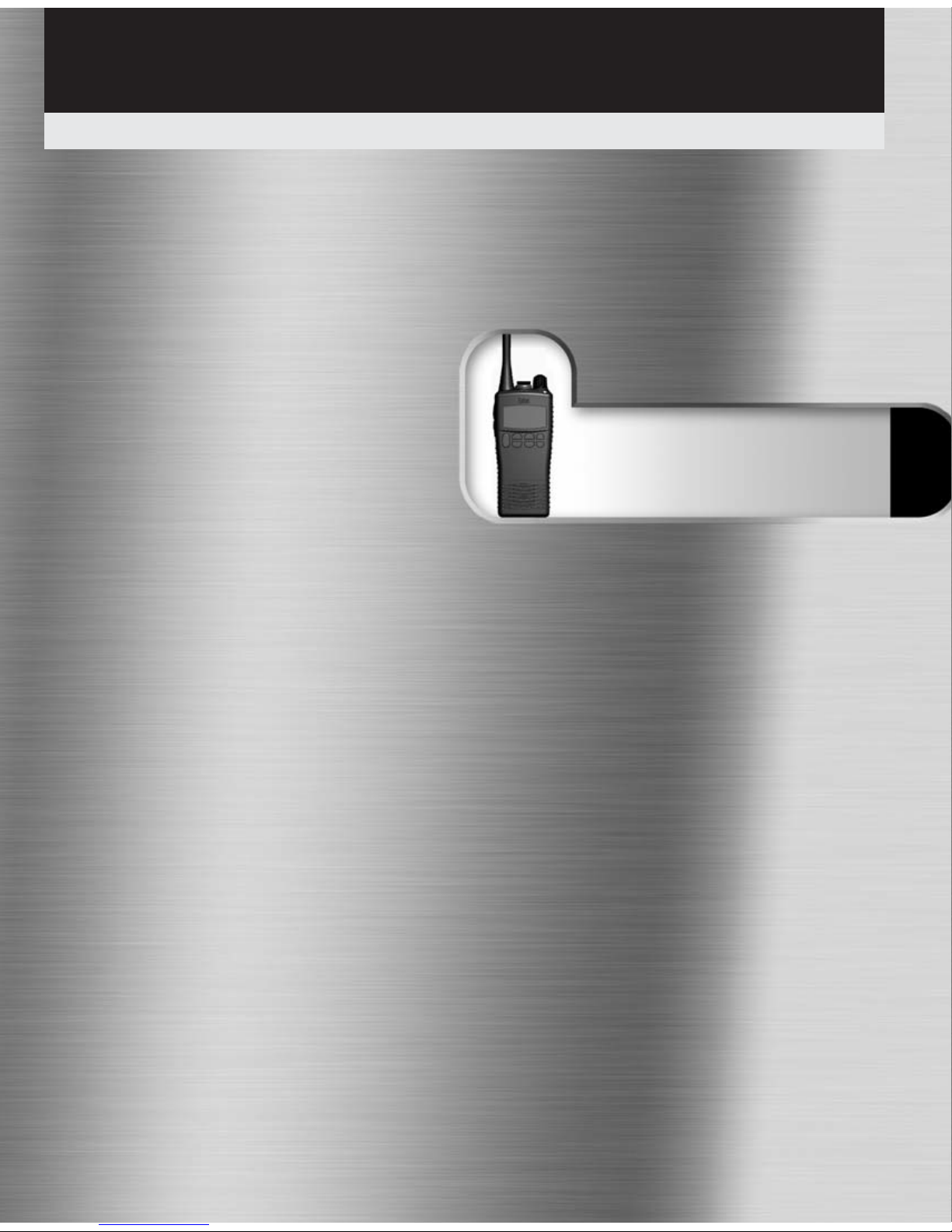
Professional submersible marine handheld transceivers
HT644
LCD
www.busse-yachtshop.de | [email protected]
Page 2

Topic Page
Certification 2
Introduction 3
Packing List 3
Radio Care 3
Preparing Your Radio For Use 4
Battery Care / Information 5 & 6
Using Your HT644 7
Reception 7
Transmitting 7
Channels 8 & 9
Functions 10
The Scan Function 10
VOX (Voice Operate Transmit) 10
LCD Indicators 11
Optional Accessories 12 & 13
Standard Features 13
Controls 14 & 15
Glossary of Terms 16
Troubleshooting 17
Channel Chart 18 & 20
Technical Specifications 21 & 22
Notes 23 & 24
TOC
Table of Contents
1
www.busse-yachtshop.de | [email protected]
Page 3

2
Certificate
Declaration of Conformity
Introduction
We Entel UK Limited of:
320 Centennial Avenue
Centennial Park
Elstree
Borehamwood
Hertfordshire
WD6 3TJ
United Kingdom
Declares under our sole responsibility that the product range:
HT644 Series Handheld Radio Transceiver
Conforms to the following standards or other nominative docum ents:
• EN 301 178 -2 V1.2.2: 2007-02, EN 60945:2002, EN6095 0-1: 2006, in accordance with
Directive 1999/5/EC.
Serial Number ________________________________
M Austin
Quality Manager
1 October 2010
Date:
www.busse-yachtshop.de | [email protected]
Page 4
Warranty
The HT644 comes with a 24 month warranty,
for details see our full terms & conditions.
Advice
• Do not use options or accessories not
specified by Entel
• Ensure that the radio is used within the
parameters for which it was designed
• Please switch the transceiver off before
connecting optional accessories
Warning
Turn the transceiver off in the following
locations:
• In explosive atmospheres (flammable gas,
dust including metallic & grain powders etc)
• Whilst taking on fuel or while parked near a
fuel station
• Near explosives or blasting sites
• In aircraft, medical institutions or near
persons known to be wearing a pacemaker
Caution
• Do not disassemble or modify the
transceiver for any reason
• Do not transmit while touching the antenna
terminal or any exposed metallic parts of the
aerial as this may result in a burn
• Please check and observe regulations in your
country with regard to use whilst driving
End of Life Disposal
When your Entel transceiver reaches the end of its
useful life, please ensure that the unit is disposed of in
an environmentally friendly way. For country specific
information please see www.entel.co.uk/recycling.
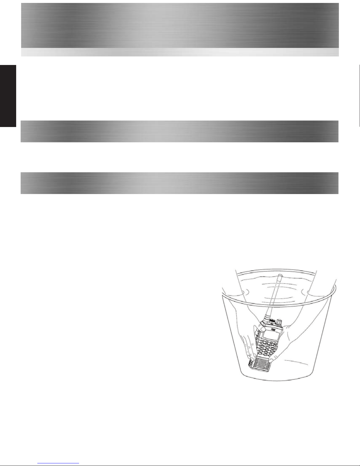
Cleaning your Radio
After exposure to any potentially corrosive substance
including salt water it is recommended to thoroughly
wash the transceiver in fresh water. If washing with the
battery removed from the radio, ensure that the
battery is not immersed in water & that the accessory
cap is attached & clean only with a damp cloth.
Introduction
3
Introduction
The Entel HT644 is a professional marine handheld transceiver that operates on the VHF marine band.
The HT644 has 58 marine international channels, 10 weather & 36 dealer programmable private
channels. The 58 marine channels are switchable to comply with USA, International or Canadian
regulations. This is done via the radio’s keypad. It has an emergency channel, which can be immediately
selected from any channel using the red 16/9 button. Weather channels can also be accessed immediately
using the [WX] key. The HT644 includes the following features: Scan, A/B quick access channels, battery
life indicator, VOX (voice activated transmit), low battery indicator, large LCD with back light.
• HT644 Transceiver
• CNB750E Rechargeable 1800mAh Li-Ion battery
• CBH750 Spring loaded belt clip
Packing List
• CATXX Antenna
• CCA trickle charger included with certain models
Radio Care
Note: Do not
wash the
transceiver if
you suspect the
waterproofing
seal may be
damaged. Please
return to your
supplier for
inspection /
repair.
www.busse-yachtshop.de | [email protected]
Page 5
Preparing Your Radio For Use
4
Preparing
5
6
a
b
---
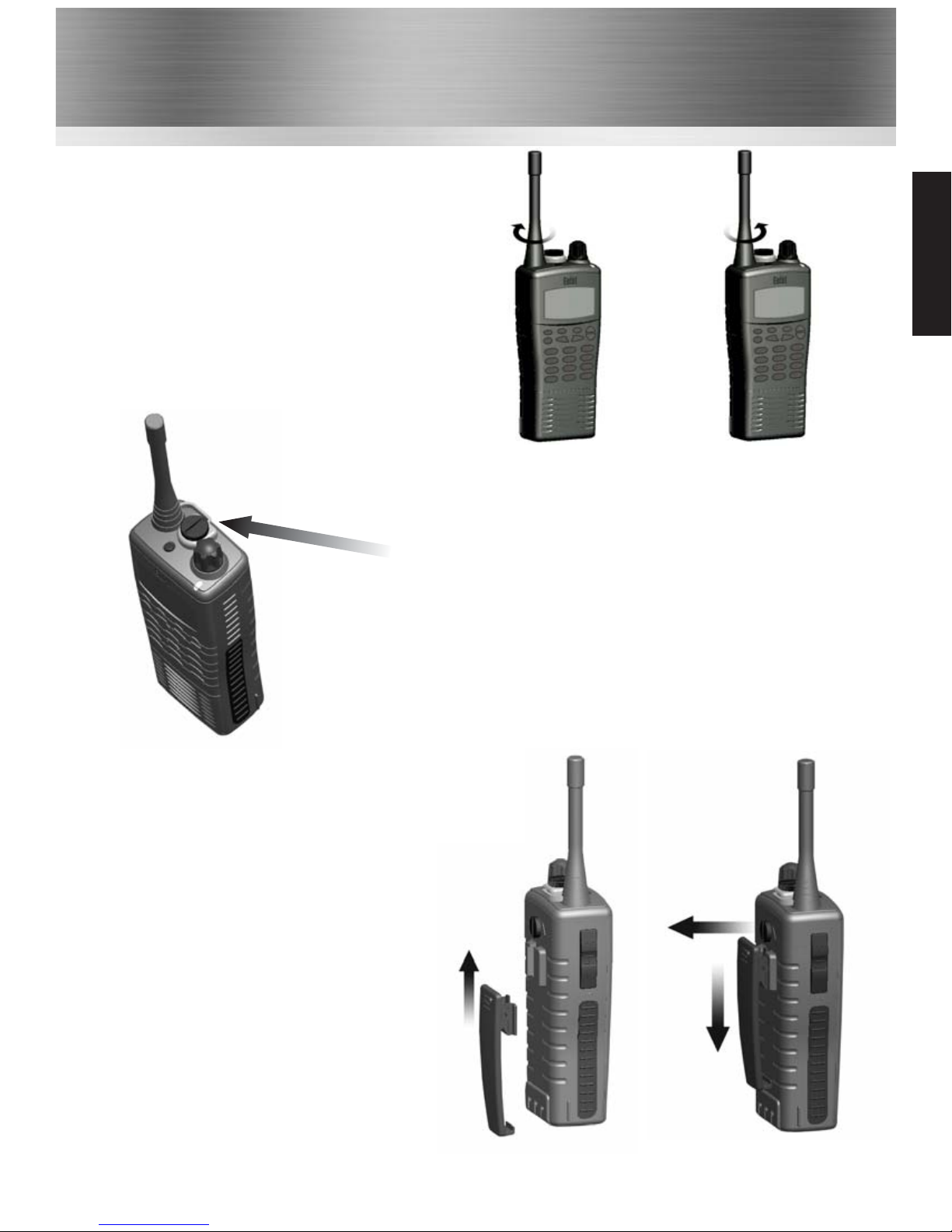
Attaching / Removing the Belt Clip
5
To attach, slot the clip onto the slot on the
b ack of the battery and slide up until you
hear a “click”
6
To remove, pull the tab towards the belt
clip (a). Then slide the belt clip
downwards (b)
Attaching / Removing the Aerial
1
To attach, carefully align the aerial with the
socket. Screw in the aerial clockwise (taking
care not to cross the thread) until it is seated
firmly with the accessory cover’s rubber ring
between the aerial & the the top of the radio.
2
To remove, unscrew the aerial anti-clockwise.
1
2
Attaching / Removing Audio Accessories
3
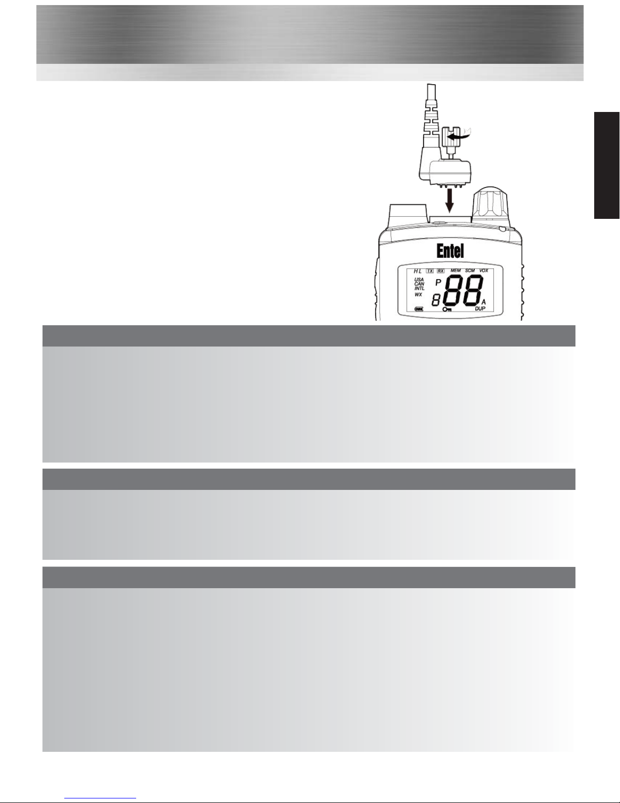
To attach, remove the accessory cover by unscrewing the
locking screw anti-clockwise (leave cover secured under
antenna as this provides a waterproof seal). Attach accessory
plug by locating over the socket. Carefully tighten the locking
screw clockwise until finger tight (do not tighten with a
screwdriver etc).
4
To remove, unscrew accessory plug the locking screw by
hand in an anti-clockwise direction (carefully use a coin or
screwdriver if too tight). Ensure you re-fit the accessory
waterproof cover so as to protect the accessory socket.
www.busse-yachtshop.de | [email protected]
Page 6

Introduction
Your Entel radio is supplied with a high
performance Lithium-Ion (Li-Ion) battery. These
batteries:
• Extend talk time
• Reduce the battery’s size and weight
• Do not suffer from ‘memory effect’ that
reduces the life of Ni-Cad and NiMH
batteries
• Have a low toxicity, therefore reducing the
impact on the environment
Battery Pack
• If a battery is not to be used for an
extended period of time (e.g. several
months) remove the battery pack from the
equipment and store in a cool and dry
location (around 0°C) part charged.
Do not fully discharge the battery before
storage
• Each charge cycle reduces the battery’s life.
Minimise the number of times you charge
your battery especially in hotter
environments which further shortens a
battery’s life
5
Battery Care / Information
Battery Pack Precautions
• Switch the transceiver OFF before
charging
• Charge the battery pack before use
• Do not recharge the battery pack if it is
already fully charged.
• Charge the battery in accordance with the
instructions enclosed with your charger
• Do not charge the transceiver and /or
battery pack if they are wet.
The battery pack includes potentially
hazardous components. Please:
• Do Not disassemble or reconstruct
battery
• Do Not short-circuit the battery
• Do Not incinerate or apply heat to the
battery
• Do Not immerse the battery in water
unless attached securely to the radio or
get it wet by other means
• Use only the specified charger and
observe charging requirements
• Do Not pierce the battery with any
object or strike it with an instrument
• Do Not use the battery pack if it is
damaged in any way
• Do Not reverse-charge or reverseconnect the battery
• Do Not touch a ruptured or leaking
battery.
If liquids from the battery get into your eyes,
immediately:
• Wash your eyes out with fresh water &
avoiding rubbing them.
• Seek medical treatment.
Battery
www.busse-yachtshop.de | [email protected]
Page 7
Battery Charging
1. Connect the AC adapter to the charger
pod. The LED status light will illuminate
green indicating ready for charge
2. Turn the transceiver off
3. Insert the battery pack into the charger
pod, either with or without the
transceiver attached. The LED status light
changes from green to RED & trickle
charge begins
4. A fully discharged battery pack will take
approximately 6 hours to charge,
depending on the remaining power
condition. When charge is complete, the
LED status light turns green.
Overcharging:
The battery pack has an over-current
protection circuit fitted. When charging a
completely discharged battery i.e. first charge,
ensure the battery is removed from the radio
and then re-attached (if fitted to radio when
charging). This will reset the protection
circuitry and ensure normal operation. This
process will need to be repeated if the battery
is allowed to completely discharge in the
future. In normal use this is unlikely.
6
Battery Care / Information
Battery Indicator
For your safety and convenience your
transceiver continually monitors the battery
pack and gives an indication on the LCD:
• 3 Segments: 12 hours
• 2 Segments: 1 hour
• 1 Segment: 20 mins
Note: Only genuine Entel batteries should be
used. Customer satisfaction is assured as you
can not be supplied with sub standard,
potentially dangerous battery packs from 3rd
party manufacturers, ensuring it delivers the
expected capacity and endurance.
On HT series batteries a breathable
membrane is used. This is clearly marked on
the battery label. Piercing the membrane will
allow water ingress to the battery, & will
invalidate the warranty.
Battery
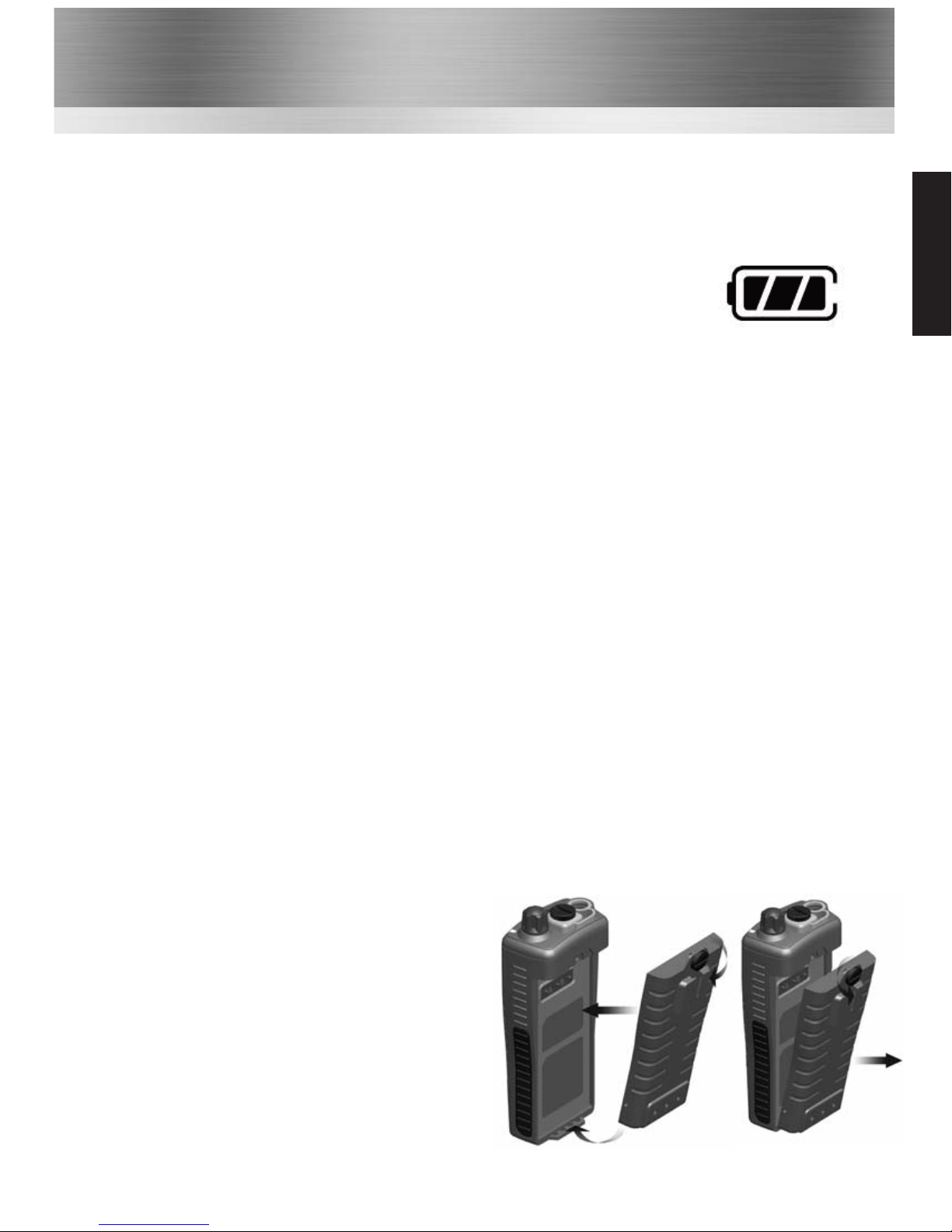
Attaching / Removing the Battery Pack
1
To attach, locate the pegs on the bottom of the
battery into the slots on the radio and press the
top of the battery against the radio. Secure
battery by tightening the screw clockwise by
hand. (Do not over tighten)
2
To remove, unscrew the locking screw
anticlockwise & pull the battery away from the
top of the radio.
1
2
www.busse-yachtshop.de | [email protected]
Page 8

7
Using Your HT644
1. To Turn the radio on rotate the volume control clockwise, to select the desired audio level
continue rotating the control clockwise. to increase volume & counter clockwise to decrease.
After power-on, the transceiver will always default to the last channel selected.
2. One second after start-up a tone is generated to indicate the transceiver has passed its
self-diagnostic test. During standby the LED indicator will pulse amber every 3 seconds, to verify
its circuitry is functioning correctly.
3. Use the [UP/DOWN] keys to select a desired channel. A full listing of all available channels can be
found on page 17-18.
4. When receiving a signal the LED indicator illuminates green & an “RX” is displayed on the LCD.
5. While the radio is operating, if you hear white noise you may need to adjust the squelch threshold
of the radio, for more information see page 8 “Adjusting Squelch Threshold”. On some channels a
slight adjustment of the squelch threshold is needed as some channels have a higher noise level
than others.
Reception
Transmitting
1. Perform steps 1 through 3 of RECEPTION.
2. Before transmitting, monitor the channel and make sure it is clear.
3. For communications over short distances, press the [H/L] key and select low power (1 watt).
Transmitting on 1 watt prolongs battery life, and should be selected whenever possible.
4. When receiving a signal, wait until the signal stops before transmitting. The transceiver cannot
transmit and receive simultaneously.
5. Press the [PTT] (Push-To-Talk) button to begin your transmission. To confirm transmission in
progress the LCD indicator illuminates TX and the LED illuminates RED.
6. Hold the transceiver 1 inch from your mouth and speak slowly and clearly into the microphone.
7. When the transmission is finished release the [PTT] button.
Turning The Radio On & Off
Turn the ON/OFF control on the top of the radio clockwise until the LCD iluminates & a short
beep is emitted. To turn the radio off turn the ON/OFF control anti-clock wise until the LCD
deluminates.
Using Your radio
Before using your radio you may need to adjust the volume on the radio to take in to account
background noise. Adjust the volume using the rotary control on the top of the radio.
Channels
www.busse-yachtshop.de | [email protected]
Page 9

Using Your
8
Channels
INT, USA & Canadian Modes
In compliance with worldwide license regulations the following versions of HT644
are available:
Version A: INT, USA & Canadian modes
Version B, C & D: INT mode only
1. In the case of version A only; to change the channel set of the transceiver, hold down the
[WX] key. The mode changes from USA to Canadian to International.
2. Refer to the marine channel charts in this booklet for allocated channels in each mode.
NOAA Weather Channels
(Applicable to version A model only)
1. To receive a weather channel, press the [WX] key. The transceiver enters into weather
channel mode.
2. There are 10 weather channels. Use the & buttons to select the desired channel.
3. To exit from the weather channels press the [WX] key. The transceiver recalls the previous
working channel.
Emergency Channels
To select the emergency channel, press the [16/9] button from any channel. Channel 16 appears
on the display. To recall the previous channel used, press the [16/9] button once again.
Channel 9
Channel 9 is used as a hailing channel for initial, non-emergency contact with other vessels. Hold
down the [16/9] key for 1 second to select channel 9.
To recall the previous channel used, press the [16/9] button twice.
Monitor Channels
Press the blue monitor button on the top of the radio to defeat the squelch mute and release
button to mute radio. A long press (radio will beep) will hold the squelch mute open until
pressed again to cancel again to return to squelch mute.
Adjusting Squelch Threshold
Press & hold the blue monitor button on the top of the radio and switch radio on, then after the
radio emits a beep release the blue button. This will cause the radio to display a number
representing the squelch threshold from 01-16, 01 is the more sensitive & 16 is the less sensitive.
Use the UP & DOWN channel buttons to adjust the level & press MEM to store the
new squelch level.
www.busse-yachtshop.de | [email protected]
Page 10

SIMPLEX / DUPLEX CHANNEL USE
Your transceiver has been factory programmed in accordance with FCC (USA), Industry Canada
and International regulations. The mode of operation cannot be altered from simplex to duplex
or vice versa. Simplex or duplex mode is automatically activated, depending on the channel and
the channel set and whether USA, Canadian, or International mode is selected.
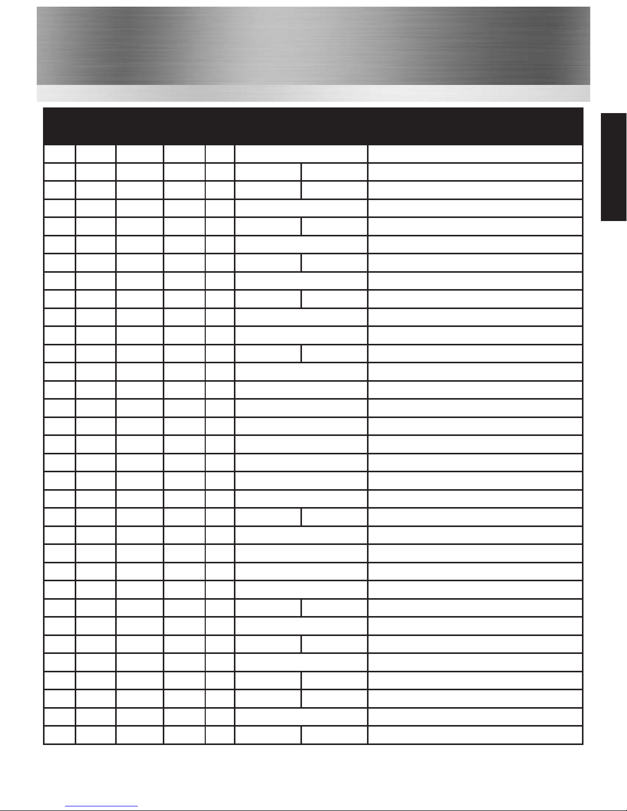
Refer to the channel charts listed on pages 18-20 of this user manual.
If you have a licence to use a specific simplex or semi-duplex channel, contact your dealer who
may be able to programme your channel using the transceiver’s private channel memory.
CHANNEL A/B INSTANT ACCESS
For your convenience, two user assigned channels can be programmed for instant access. If the
[A/B] key is pressed and no channel A or B has been assigned, a short beep will be heard.
PROGRAMMING A/B INSTANT ACCESS BUTTONS
1. Hold down the [A/B] key and turn on the transceiver.
2. The letter A will appear on the display and dashes "_ _" indicate that no channel has been
designated channel A.
3. Press the [UP/DOWN] button until the desired channel number is displayed.
4. With the desired channel number displayed, press the [MEM] key once. The "A" will stop
flashing, indicating that the displayed channel is now designated channel A.
5. Press the A / B button again. The letter "b" will appear on the display.
Repeat steps 2 through to 4.
6. Switch transceiver off and on to exit this mode and save changes. If you wish to clear instant
access channels follow step 1 then press the [MEM] key. The “A” will flash. Now switch the
transceiver off and on again.
Note: Should you later wish to delete any stored channels simply press "MEM" key whilst in
A/B programming mode.
OPERATION OF A/B INSTANT ACCESS BUTTONS
Pressing the [A/B] button will toggle between A, B and the previous selected working channel.
Channel A is represented by the "A" to the left of the channel number on the LCD, & channel B
is represented by "B".
Note: Do not confuse this "A" with the one that is sometimes displayed to the right hand side
of the channel number (in USA and Canadian modes)
9
Channels
Channels
www.busse-yachtshop.de | [email protected]
Page 11

Functions
10
The Scan Function
1. Select the desired channel to be scanned using the & buttons.
2. Press the [MEM] button to store the channel in the transceiver’s memory. [MEM] is
displayed on the LCD. This channel is now memorised to be scanned.
3. To add further channels, repeat steps 1 & 2.
4. To delete a channel from the transceiver’s scan list, press the [MEM] button on a channel
that displays the [MEM] icon until the icon disappears.
5. All channels programmed remain in the transceiver’s scan memory, even if the power is
switched off.
6. Adjust the squelch control until the white noise is eliminated.
7. To start scanning, press the [SCAN] key. The scan proceeds from the lowest to the highest
programmed channel number & stops on channels when a transmission is received.
8. To stop the scan at any time, press the [SCAN] key again.
VOX (Voice Operated Transmit)
Press the [MEM] button & switch the transceiver on. The VOX symbol & a "0" will flash. "0"
indicates VOX is switched off, 1 is for low sensitivity, 5 is for normal sensitivity, and 9 is for
high sensitivity. Use the [UP/DOWN] button to select the desired level, press [MEM] to
confirm, the transceiver is now set to VOX. To switch VOX off, go back into VOX programming
mode by holding the [MEM] key whilst switching on. Press the UP/DOWN button until the
vox level is "off" and press [MEM] to confirm.
In VOX mode the transceiver will react to your voice, and transmit automatically without you
having to press the PTT button. There is always a slight delay for the electronic switching &
consideration will need to be given. To get optimum performance from the VOX feature you
should use a noise cancelling headset or earpiece microphone (see accessory options).
Functions
www.busse-yachtshop.de | [email protected]
Page 12
11
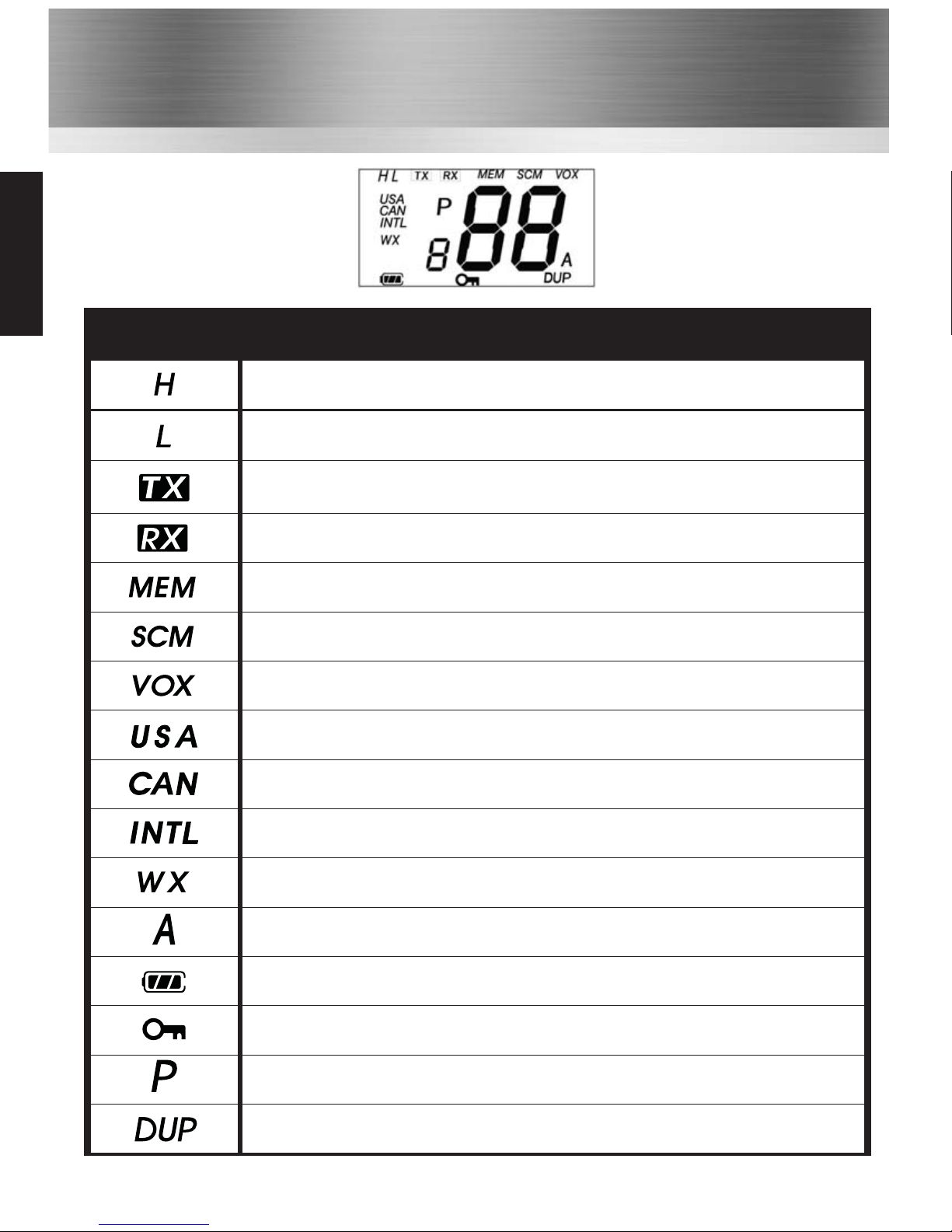
LCD Indicators
Indicator Description
High power selected (5 Watts)
Low power (1 Watt).
The Radio is Transmitting.
The Radio is Recieving.
Indicated channel is memorised for scanning.
Scrambler mode enabled (version A & B only).
Voice operated transmit mode enabled.
Indicates the channel set for USA.
Indicates the channel set for Canadian.
Indicates the channel set for International.
NOAA weather channels selected (USA & Canadian waters only).
A ship-to-ship channel (in USA or Canadian mode).
Battery life indicator.
Indicates keypad is locked, excluding the PTT, H/L & LAMP buttons.
Private channel number selected.
Duplex channel selected (not simplex).
LCD
www.busse-yachtshop.de | [email protected]
Page 13
Accessories
Carry Options
CFC750 HT64X soft leatherette case finished in black with carry strap
CLC752
HT642, HT648 heavy duty black leather case with strap & belt loop
CLC753 HT644 & HT649 heavy duty black leather case with strap & belt loop
CBH750 Spare spring loaded belt clip
Audio Accessory Options
CMP1/750 Compact medium duty speaker microphone with earpiece jack
CMP750
Heavy duty submersible speaker microphone
EHP9 D-shaped earpiece (plugs into CMP1/750 or CMP750 above)
EA12/750 D-shaped earpiece with in-line PTT/microphone & VOX*
EA15/750 Earpiece microphone with transparent acoustic tube & VOX*
EA19/750 D-shaped earpiece with boom microphone and in-line PTT & VOX*
EHP750 D-Shaped earpiece (connects directly to radio)
EPT40/750 Bone conductive earpiece microphone with PTT
CXR5/750 Bone conductive skull microphone with in-line PTT
CXR16/750 D-shaped earpiece and throat microphone with in-line PTT
12
Battery & Charger Options
CNB750E Spare 1800mAh Lithium-Ion battery pack with rear clip
CLB750G
Spare 2000mAh Lithium Manganese non-rechargeable battery with rear clip.
CSAHT 1-way intelligent rapid charger, 110-230v
CSBHT 6-way intelligent, rapid charger, 110-230v
CCAHT-230 1-way trickle charger with 230V mains adapter
CCAHT-110 1-way trickle charger with 110V mains adapter
CCAHT-12 1-way trickle charger with cigar lighter lead, 12V DC operation
Optional Accessories
Attaching & Removing Accessories
To attach an accessory: Remove the accessory cover
by unscrewing the locking screw anti-clockwise (leave
cover attached or store in a safe place).
Attach accessory plug to the socket. Carefully tighten the
locking screw clockwise until finger tight (do not tighten
with a screwdriver etc).
To remove an accessory: Unscrew the locking screw
of the accessory by hand in an anti-clockwise direction
(carefully use a coin or screwdriver if too tight).
Ensure you re-fit the accessory cover so as to protect
the socket.
www.busse-yachtshop.de | [email protected]
Page 14
Accessories
Optional Accessories
For complete up to date list of optional accessories visit www.entel.co.uk
13
CHP1/750 Light weight single earpiece headset with in-line PTT & VOX*
CHP750HS Single earpiece ear defender headset with boom mic and in line PTT for hard hat & VOX*
CHP750HD Double earpiece defender headset with boom mic and in line PTT for hard hat & VOX*
CHP750D Double earpiece headband defender headset with boom mic and in line PTT & VOX*
CHP750BT Bluetooth double earpiece headband defender headset with boom mic and ear cup PTT
CBH750 Spare spring loaded belt clip
* VOX = Voice Operated Transmit (hands free operation)
Standard Features:
• Environmentally protected to IP68 i.e. submersible to 5 metres for up to 60 minutes.
• Robust design, exceeds MIL-STD-810C/D/E/F.
• LCD screen to display channel number & current settings \ status.
• 1800mAH Lithium-Ion battery for superior operational time.
• INT, USA, CAN channels.
• Full transmit power output 5 Watts.
• Exceptionally loud & clear audio .
• Ch 16 \ 9 shortcut button.
• WX shortcut button.
• Scan button.
• Monitor button.
• MEM button.
• Automatic power save to further increase operational time.
• Low battery alert indicates when the battery needs charging or replacing.
• Battery charge count to indicate when a battery needs replacing.
Dealer Programmable Features:
• Key lock button
• Prefixed minimum volume level and fixed bleep level
• VOX (Voice Operated Transmit) Function.
Standard Features
www.busse-yachtshop.de | [email protected]
Page 15
14
Controls
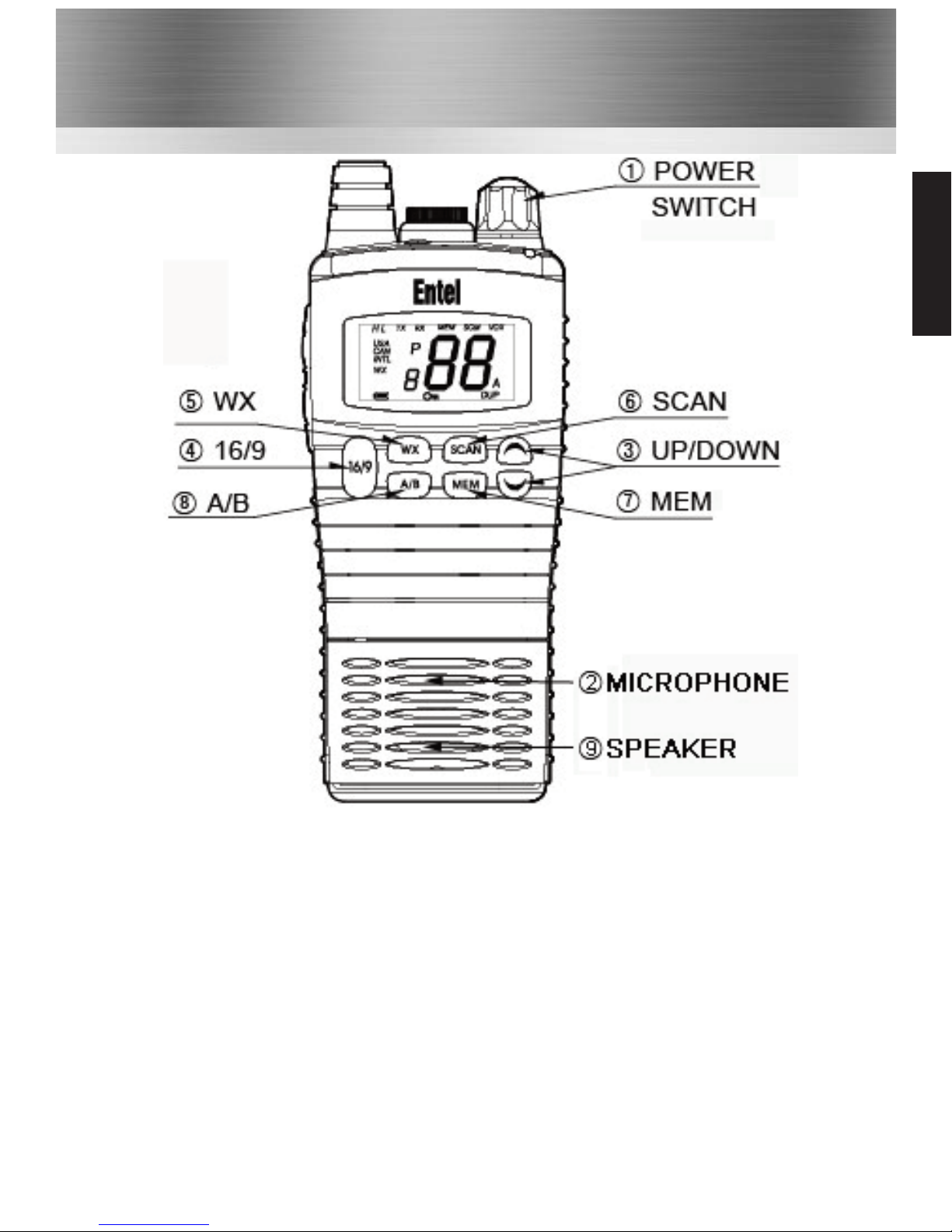
1 Power & Volume Control: Powers the radio on and off and controls the volume.
2 The Microphone: Internal condenser microphone
3 Up / Down Buttons: Press up / down buttons to change channel.
4 16/9 Button: A momentary press of the button selects channel 16 and a longer press
select channel 9.
5 WX Button: Immediately recalls the weather channels.
6 Scan Button: Starts / Stops scanning the memorised channels.
7 The MEM Button: Memorises a desired channel for scanning.
8 The A/B Button: Provides Instant access to preassigned channels (if programmed)
9 Speaker: The Radio’s Speaker.
Controls
www.busse-yachtshop.de | [email protected]
Page 16
15
Controls
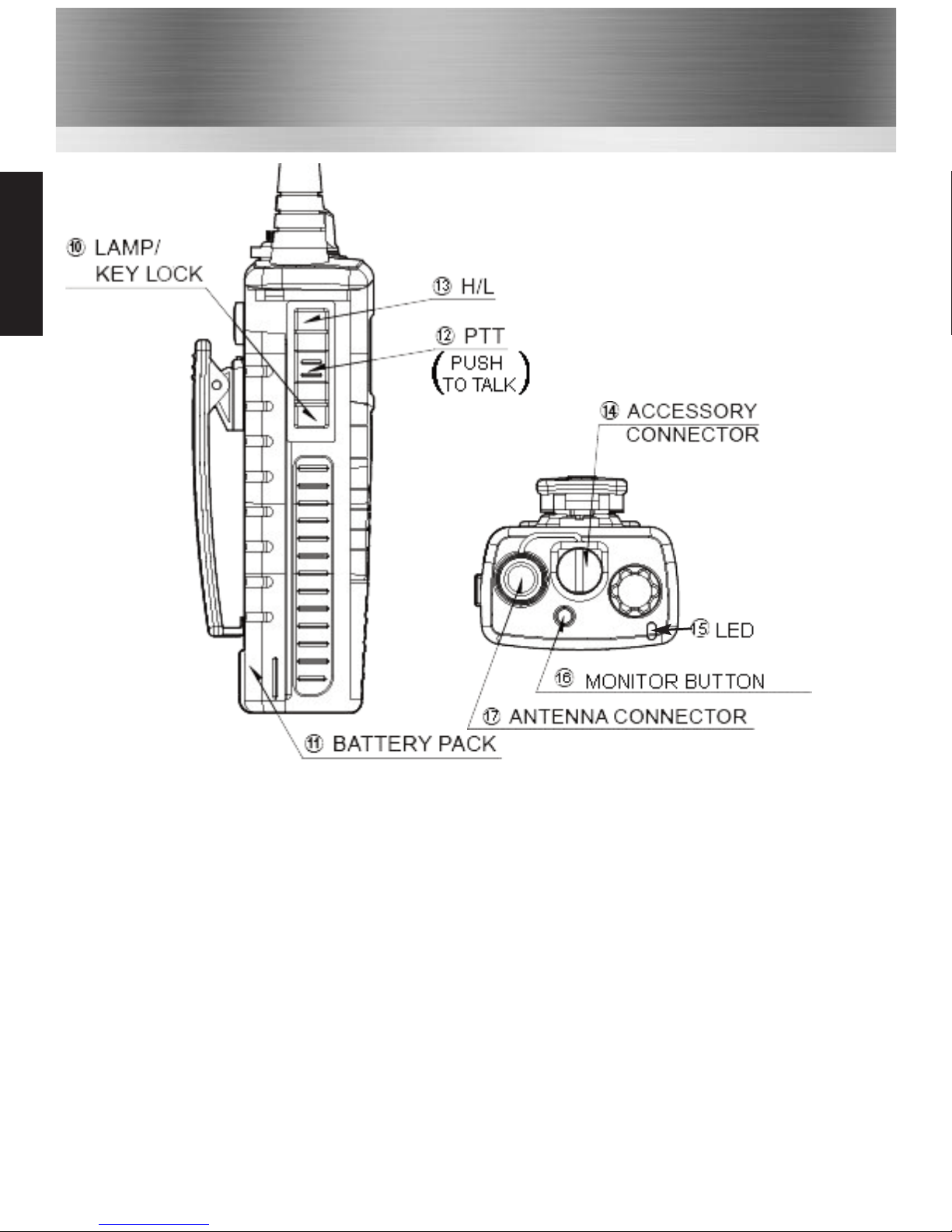
10 Lamp / Key lock Button: Momentarily pressing this button illuminates the LCD display.
Holding this button for over 1 second activates the key lock. To deactivate the key lock
press & hold the button again until the lock removes.
11 The Radio’s Battery Pack: Rechargeable lithium-ion battery pack.
12 PTT (Push To Talk Switch): Hold down to transmit, release to receive.
13 H/L Button: Press and hold this button for 1 second to toggle between high and low
power (1 & 5 Watts).
14 The Accessory Connector: Used to attach any HT644 approved accessory.
15 LED Indicator: Indicates the status of the radio:
• RED Steady = Transmitting
• RED Flashing slowly = Battery needs re-charging
• GREEN Steady = Receiving
16 Monitor Button: Press to monitor the channel without the squelch mute.
17 Antenna Connector: Use to attach the antenna of the radio.
Controls
www.busse-yachtshop.de | [email protected]
Page 17
16
Glossary of Terms
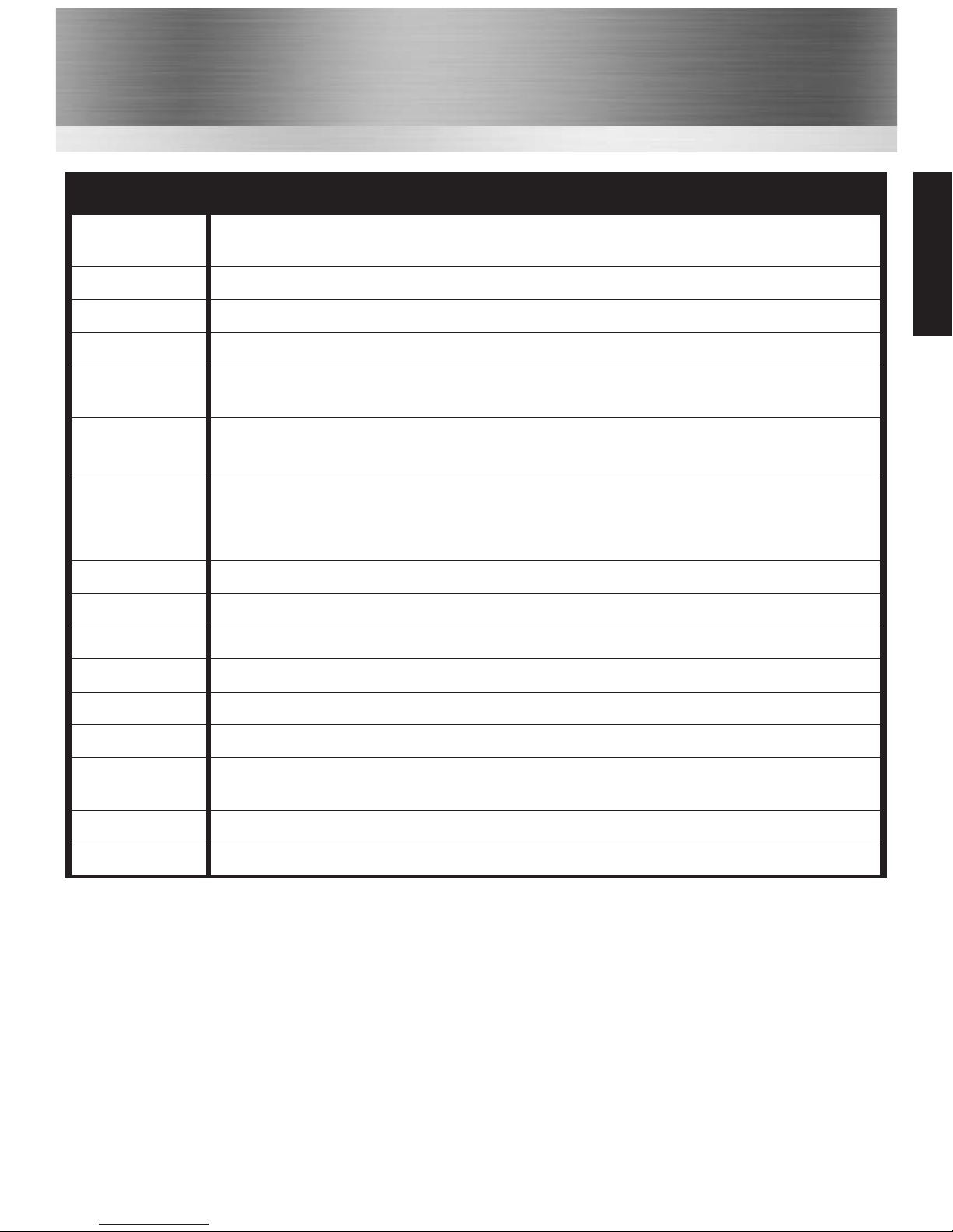
Term Description
Canadian
Channels
Channels designated as defined and regulated by Industry Canada, (RIC),
Marine Communications & Traffic Services.
Duplex Transmit and receive on different frequencies.
Encryption Scrambled audio for extra privacy.
FM Frequency Modulation.
International
Channels
Channel designations as defined for use in international waters by the
International Telecommunications Union (ITU).
Marine
Channels
Special channels reserved for marinas located in selected European
countries. These channels are pre-programmed in the transceiver as P1 & P2.
Private
Channels
Channels which are assigned by regulatory agencies governing VHF radio use
for a specific region or country. These channels are prefixed with a "P" and
can only be programmed into the transceiver by authorised dealers.
PTT Press To Talk (Transmit)
RX Receive
Simplex Transmit and receive on the same frequency.
Squelch To suppress background noise
TX Transmit
Transceiver A device that can transmit and receive
USA
Channels
Channel designations as defined by the Federal Communications Commission
(FCCVOX )
VOX Voice Operated Transmit
VHF Very High Frequency (30MHz to 300 MHz)
Glossary
www.busse-yachtshop.de | [email protected]
Page 18
17
Troubleshoot
Troubleshooting
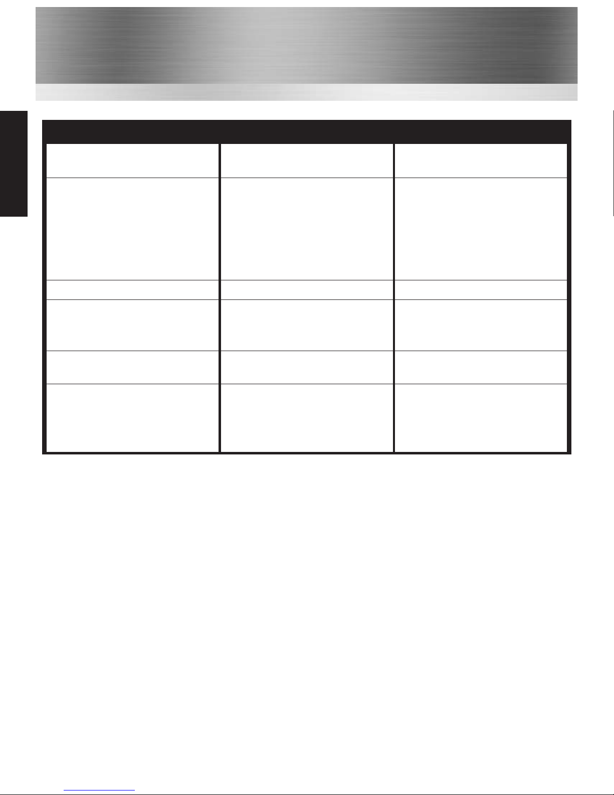
SYMPTOM PROBABLE CAUSE REMEDY
Transceiver not switching on
Battery needs charging or
battery is exhausted
Charge the battery pack
replace the battery pack
The scan key does not start
the scan
No channels memorised
(MEM) Squelch is not adjusted
Use the MEM key to enter
desired channels into scan
memory. Adjust the squelch to
threshold or to the point
where the white noise just
disappears.
Cannot change any function Key lock is switched on Turn key lock off
The LED on the charger does
not illuminate when charging
Defective battery or charger.
Dirty terminal contact on
battery or charger
Contact your dealer Clean
contacts with dry clean cloth
No transmit or cannot select
high power
Some channels are low power
only Battery pack exhausted
Change to high power channel
Charge / replace the battery
Transceiver transmits without
pressing PTT button Buttons
seem to work intermittently
VOX has been enabled
Hold MEM button for 2 secs,
use UP or DOWN button &
select “off” to turn VOX
off
www.busse-yachtshop.de | [email protected]
Page 19
Channel Chart
18
Channel Chart
CH
Channel Set
S/D
Frequency
Channel Use
USA CAN INT
Receive Transmit
1A
X
S 156.05000
PORT OPERATION AND COMMERCIAL
1
X X
D 160.65000 156.05000
PUBLIC, PORT OPERATIONS
2
X X
D 160.70000 156.10000
PUBLIC, PORT OPERATIONS
3A
X
S 156.15000
US GOVERMENT, COAST GUARD
3
X X
D 160.75000 156.15000
PUBLIC, PORT OPERATIONS
4A
X
S 156.20000
COMMERCIAL FISHING
4
X
D 160.80000 156.20000
PUBLIC, PORT OPERATIONS
5A
X X
S 156.25000
PORT OPERATIONS, VTS IN SEATTLE
5
X
D 160.85000 156.25000
PUBLIC, PORT OPERATIONS
6
X X X
S 156.30000
INTER-SHIP SAFETY
7A
X X
S 156.35000
COMMERCIAL
7
X
D 160.95000 156.35000
PUBLIC, PORT OPERATIONS
8
X X X
S 156.40000
COMMERCIAL (INTER-SHIP ONLY)
9
X X X
S 156.45000
BOATER CALLING CHANNEL
10
X X X
S 156.50000
COMMERCIAL / INTERSHIP
11
X X X
S 156.55000
COMMERCIAL / PORT OPERATIONS
12
X X X
S 156.60000
PORT OPERATION
13
X X
S 156.65000
INTER-SHIP NAVIGATION SAFETY
13
X
S 156.65000
INTER-SHIP NAVIGATION SAFETY
14
X X X
S 156.70000 PORT OPERATION
15
X
R 156.75000 - SHIP MOVEMENT
15
X X
S 156.75000 SHIP MOVEMENT \ INTERSHIP
16
X X X
S 156.80000 INTERNATIONAL DISTRESS
17
X X X
S 156.85000 STATE CONTROLLED \ INTERSHIP
18A
X X
S 156.90000 COMMERCIAL
18
X
D 161.50000 156.90000 PORT OPERATION, SHIP MOVEMENT
19A
X X
S 156.95000 COAST GUARD
19
X
D 161.55000 156.95000 PORT OPERATION, SHIP MOVEMENT
20A
X
S 157.00000 PORT OPERATION
20
X X
D 161.60000 157.00000 PORT OPERATION AND SHIPMENT
20
X
D 161.60000 157.00000 PORT OPERATION AND SHIPMENT
21A
X X
S 157.05000 U.S. GOV, CANADIAN COST GUARD
21
X
D 161.65000 157.05000 PORT OPERATION, SHIP MOVEMENT
www.busse-yachtshop.de | [email protected]
Page 20
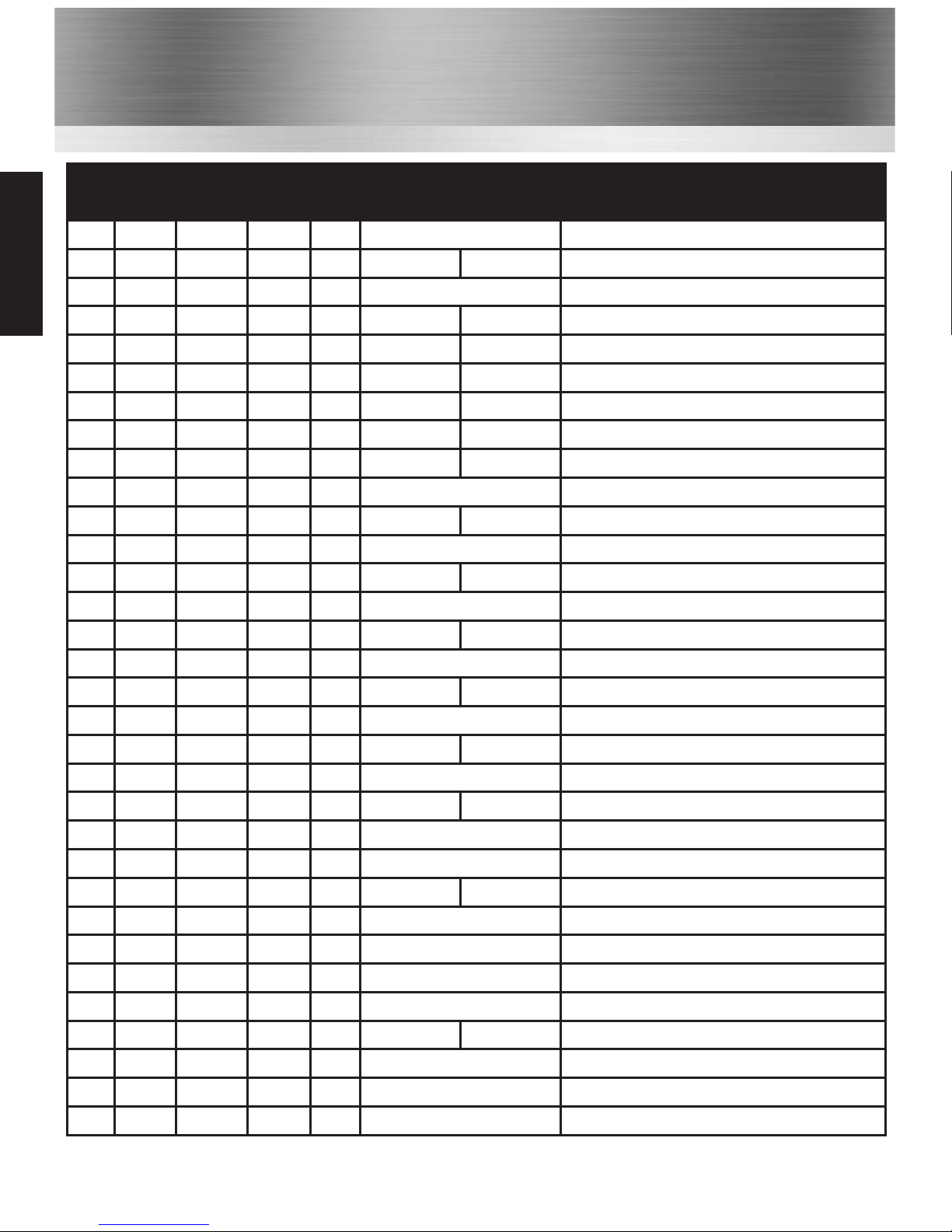
Channel Chart
19
Channel Chart
CH
Channel Set
S/D
Frequency
Channel Use
USA CAN INT
Receive Transmit
22A
X X
S 157.10000
22
X
D 161.70000 157.10000
PORT OPERATION, SHIP MOVEMENT
23A
X
S 157.15000
U.S. GOVERNMENT ONLY
23
X X
D 161.75000 157.15000
PUBLIC CORRESPONDENCE
24
X X X
D 161.80000 157.20000
PUBLIC CORRESPONDENCE
25
X X X
D 161.85000 157.25000
PUBLIC CORRESPONDENCE
26
X X X
D 161.90000 157.30000
PUBLIC CORRESPONDENCE
27
X X X
D 161.95000 157.35000
PUBLIC CORRESPONDENCE
28
X X X
D 162.00000 157.40000
PUBLIC CORRESPONDENCE
37
X
S 157.85000
MARINA CHANNEL
60
X X
D 160.62500 156.02500
PUBLIC \ PORT OPERATIONS
61A
X X
S 156.07500
-
61
X
D 160.67500 156.07500
PUBLIC \ PORT OPERATIONS
62A
X
S 156.12500
-
62
X
D 160.72500 156.12500
PUBLIC \ PORT OPERATIONS
63A
X
S 156.17500
PORT OPERATIONS
63
X
D 160.77500 156.17500
PUBLIC \ PORT OPERATIONS
64A
X X
S 156.22500
64
X X
D 160.82500 156.22500
PUBLIC \ PORT OPERATIONS
65A
X X
S 156.27500
PORT OPERATIONS
65
X
D 160.87500 156.27500
PUBLIC \ PORT OPERATIONS
66A
X
S 156.32500 PORT OPERATIONS
66A
X
S 156.32500 PORT OPERATIONS
66
X
D 160.92500 156.32500
PUBLIC \ PORT OPERATIONS
67
X X
S 156.37500 INTERSHIP
67
X
S 156.37500
68
X X X
S 156.42500 NON-COMMERCIAL
69
X X X
S 156.47500 INTERSHIP
70
X X X
R 156.25000 - DIGITAL SELECTIVE CALLING
71
X X X
S 156.57500 PORT OPERATIONS
72
X X X
S 156.62500 NON-COMMERCIAL \ INTERSHIP
73
X X X
S 156.67500 INTERSHIP
www.busse-yachtshop.de | [email protected]
Page 21
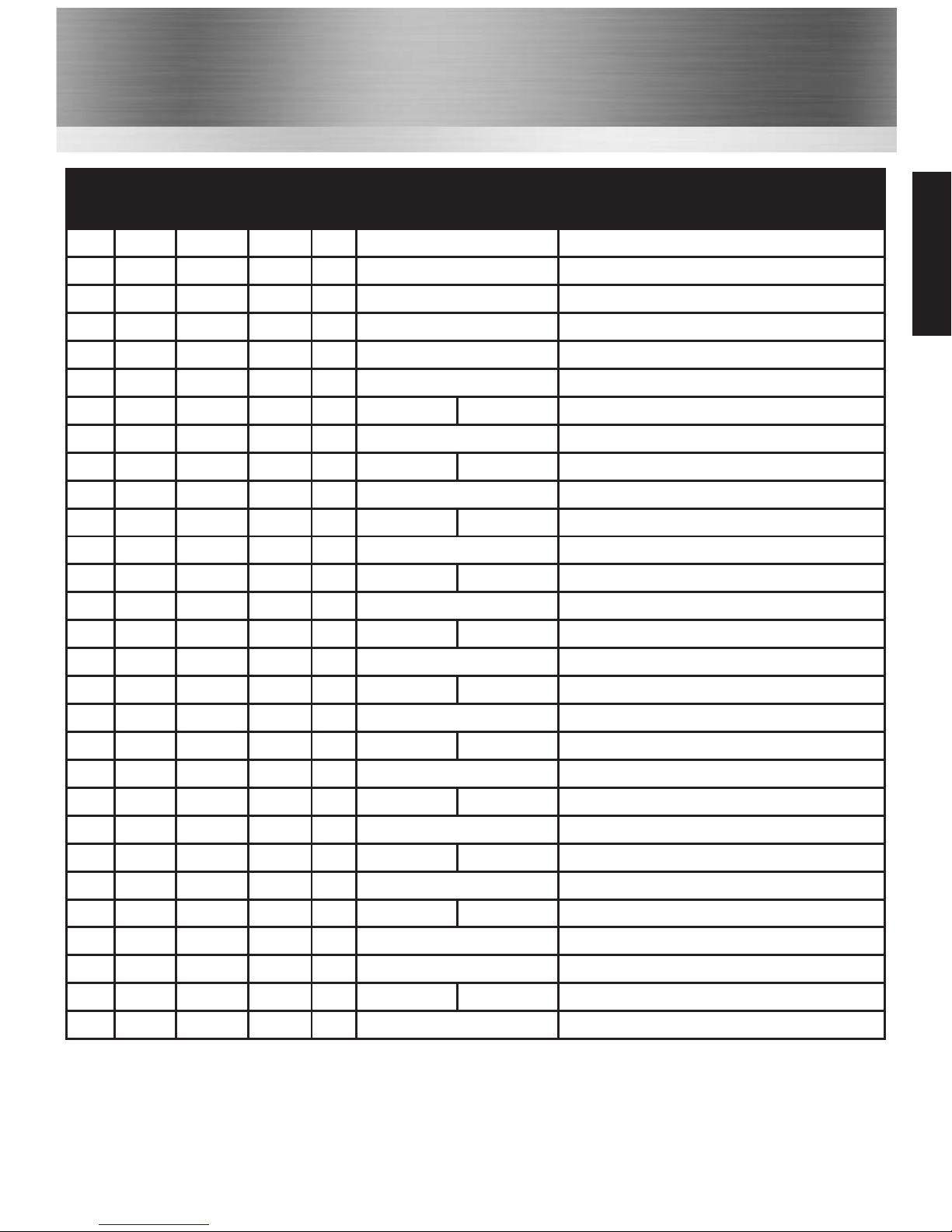
Channel Chart
Channel Chart
CH
Channel Set
S/D
Frequency
Channel Use
USA CAN INT
Receive Transmit
74
X X X
S 156.72500 PORT OPERATIONS
75
X X
S 156.77500
PORT \ GUARD CHANNELS
76
X X
S 156.82500
PORT \ GUARD CHANNELS
77
X X
S 156.87500
PORT OPERATIONS
77
X
S 156.87500
PORT OPERATIONS \ INTERSHIP
78A
X X
S 156.92500
NON-COMMERCIAL
78
X
D 161.52500 156.92500
PUBLIC \ PORT OPERATIONS
79A
X X
S 156.97500
COMMERCIAL
79
X
D 161.57500 156.97500
PORT OPERATION, SHIP MOVEMENT
80A
X X
S 157.02500
COMMERCIAL
80
X
D 161.62500 157.02500
PORT \ SHIP MOVEMENT
81A
X X
S 157.07500
81
X
D 161.67500 157.07500
PORT OPERATION
82A
X X
S 157.12500
82
X
D 161.72500 157.12500
PUBLIC \ PORT OPERATIONS
83A
X X
S 157.17500
83
X X
D 161.77500 157.17500
PUBLIC CORRESPONDENCE
84A
X
S 157.22500
PUBLIC CORRESPONDENCE
84
X X X
D 161.82500 157.22500
PUBLIC \ PORT OPERATIONS
85A
X
S 157.27500
PUBLIC CORRESPONDENCE
85
X X X
D 161.87500 157.27500
PUBLIC CORRESPONDENCE
86A
X
S 157.32500
PUBLIC CORRESPONDENCE
86
X X X
D 161.92500 157.32500
PUBLIC CORRESPONDENCE
87A
X
S 157.37500
PUBLIC CORRESPONDENCE
87
X X
D 161.97500 157.37500
PUBLIC CORRESPONDENCE
87
X
S 157.37500
PUBLIC CORRESPONDENCE
88A
X
S 157.42500
COMMERCIAL
88
X X
D 162.02500 157.42500
PUBLIC CORRESPONDENCE
88
X
S 157.42500
PUBLIC CORRESPONDENCE
Key:
• S = Simplex.
• D = Duplex.
• R = Receive Only.
20
www.busse-yachtshop.de | [email protected]
Page 22
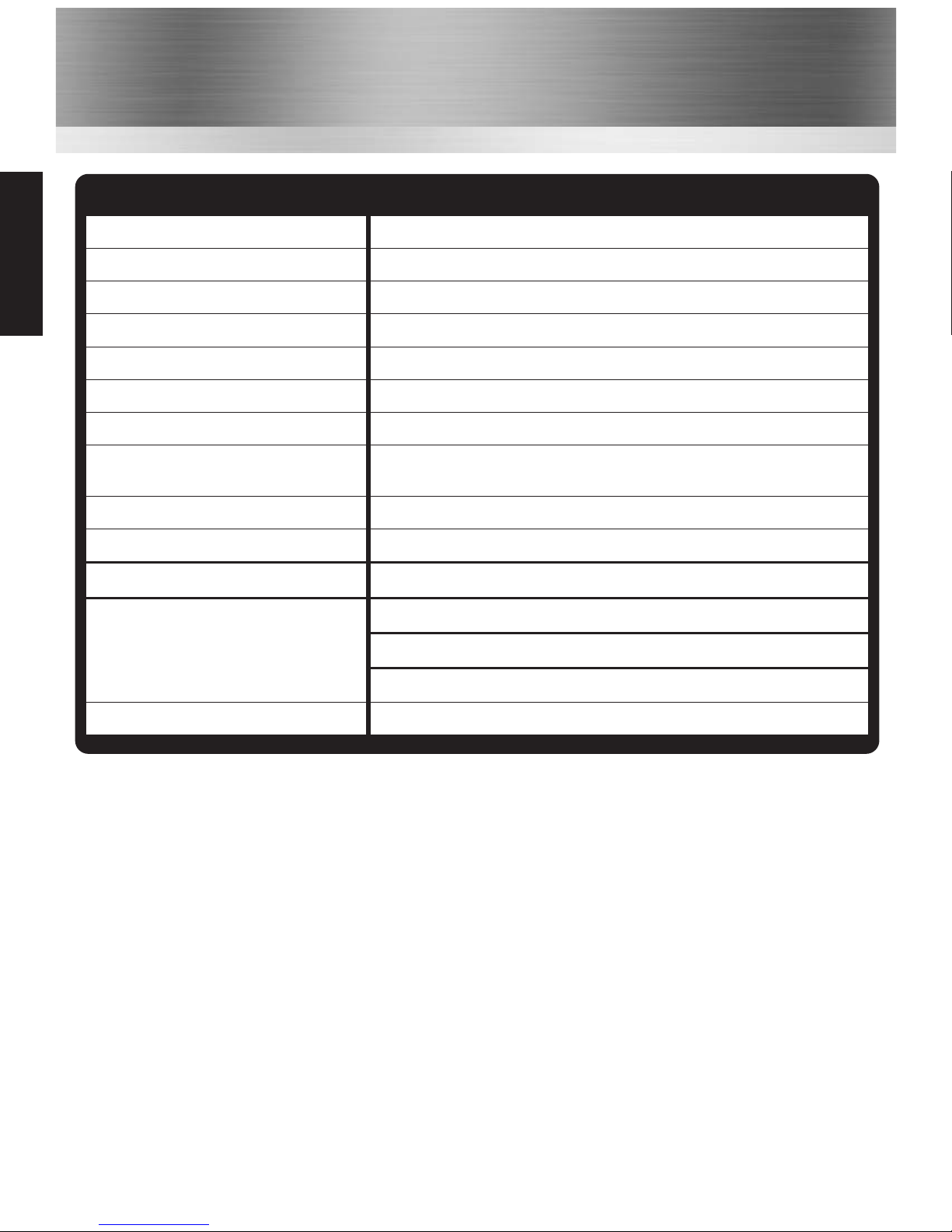
21
Technical Specifications
Frequency Range
156 - 163.275MHz
Channel Spacing
25 kHz
Communication Method
Simplex
Antenna
High Efficiency Helical
Antenna Impedance
50 ohm
Power Supply Voltage
7.4 V DC
Battery Life
8 Hours
Current Drain (nominal)
Standby 40mA; RX: 390 mA; 1.0 W audio output (1kHz)
TX: Less than 1 A at 2W, 0.7 A at 1W.
Duty Cycle
TX: 10%, RX 10%, Standby: 80%
Microphone Internal condenser microphone
Operating Temperature -20°C to 60°C
Size
Height = 130mm (145mm including knobs);
Width = 59.5mm (62mm including protrusions);
Diameter = 37mm (41mm including battery protrusions);
Weight
Less than 300g.
GENERAL
Specifications
www.busse-yachtshop.de | [email protected]
Page 23
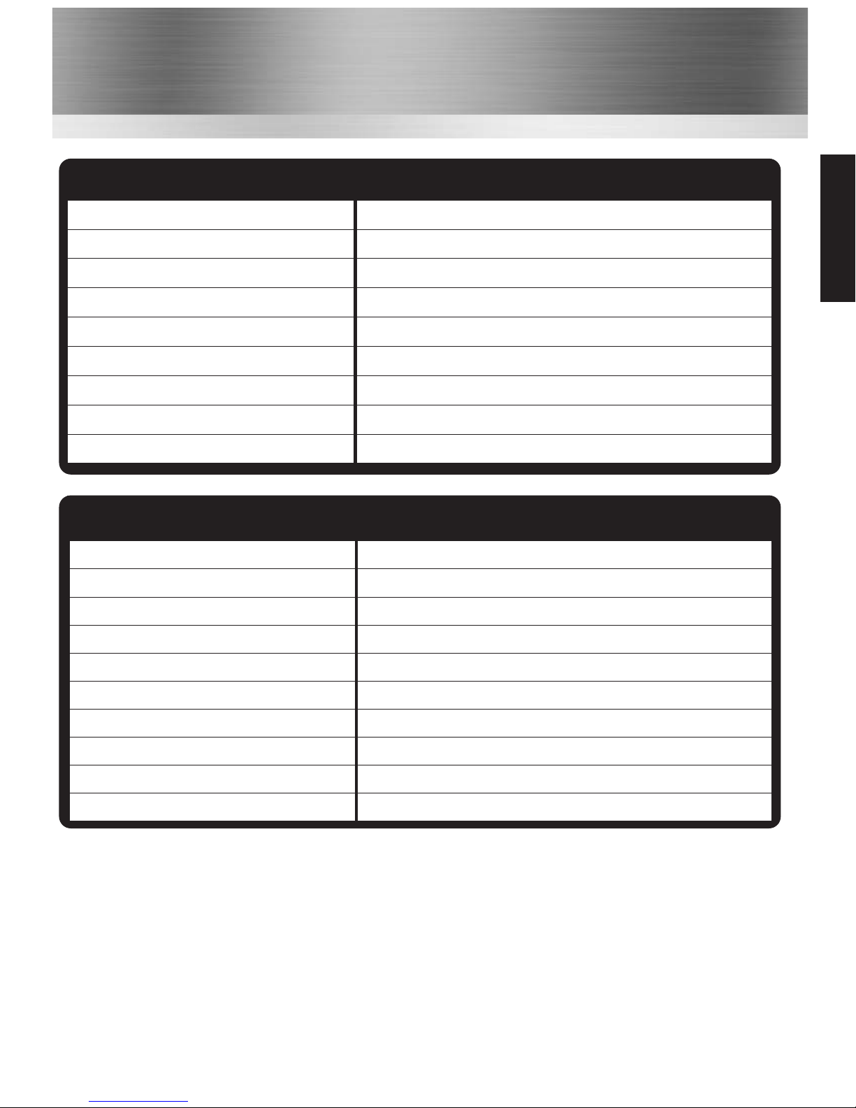
Specifications
Frequency Range
156.025 - 157.425
Power Output Selectable: HIGH = 5W, LOW = 1W
Modulation 16K0G3E
Oscillator Method PLL
Frequency Stability ±2PPM
Maximum Deviation ±5 kHz
Audio Distortion < 5% (1 kHz 60%)
Spurious Emissiong -55db
Hum & Noise -40 [dB]
TRANSMITTER
22
Technical Specifications
Frequency Range
156 - 163.275MHz
Receiver Type Double Super Heterodyne type
Sensitivity <0.25uV (12dB SINAD)
Frequency Stability ±2PPM
Spurious Rejection -60 dB
Adjacent Channel Selectivity -70 dB
Distortion < 3% Typical
Hum & Noise -40 dB
Audio Output 1W
Speaker Size 38 mm
RECEIVER
www.busse-yachtshop.de | [email protected]
Page 24

23
Notes
Use this page to record important information, such as the serial number of your radio and any
private channels programmed by your dealer etc.
Notes
www.busse-yachtshop.de | [email protected]
Page 25

Page 26
‘the
choice’
professional’s
Headquarters: United Kingdom www.entel.co.uk
Copyright Entel UK Ltd. 2009
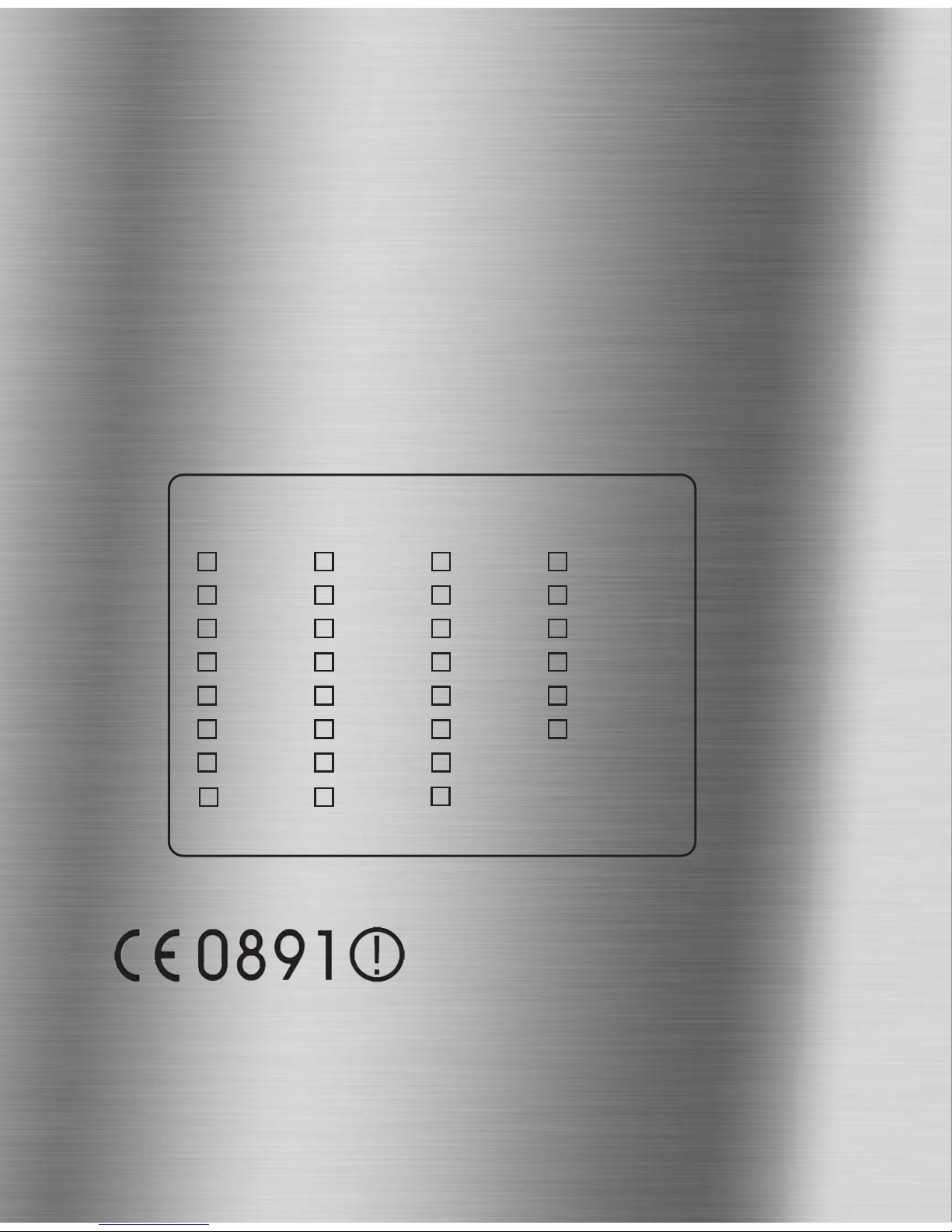
<Intended Country Of Use>
AT
BE
BG
CY
CZ
DK
EE
FI
FR
DE
GR
HU
IS
IE
IT
LV
LT
LU
MT
NL
NO
PL
PT
RO
SK
SI
ES
SE
CH
UK
Registered Community Design Application 000810890
U.S. Design Patent Pending No. 23/182,829
Copyright and Unregistered Design Right Entel UK 2009
All rights reserved
www.busse-yachtshop.de | [email protected]
 Loading...