

entegris InVue NT6520, InVue NT6510 User Manual
P/N 01-1032525 (Rev. A 09/15) CRITICAL MATERIALS HANDLING
INVUE™ INTEGRATED
FLOW CONTROLLERS,
MODELS NT6510, NT6520
User guide


INVUE INTEGRATED FLOW CONTROLLERS, MODELS NT6510, NT6520
Table of Contents
Introduction ....................... 2
Identifying Nonstandard
Product Configurations ...... 2
Principle of Operation ......... 2
Factory Configured ............. 3
Continuous versus
Batch Control ................. 3
Calibration Reference
Conditions ..................... 3
General Considerations ......... 4
Power Supply Requirements ... 4
Storage Temperature Range ... 4
Operating Ambient
Temperature Range .......... 4
Operating Process
Temperature Range .......... 4
Line Pressure .................... 4
Pressure Drop .................... 4
Dimensions ...................... 5
Installation ........................ 9
Provided Equipment ........... 9
Mounting Requirements ...... 10
Mechanical Installation ...... 11
Power Supply Requirements .. 12
Electrical Connections ....... 14
Wiring Diagram ................ 16
Optional Connections ......... 17
Setpoint Signal Setup ......... 18
Calibration Graphs ............ 19
Unit Operation .................. 20
Operating Environment ...... 20
Performance ................... 21
Operational Reliability ........ 22
Status and Alarming .......... 22
LED Status Codes ............. 23
Diagnostic Guide ................. 24
Maintenance .................... 27
Normal Operation ............. 27
Re-zero Function .............. 27
Reference ........................... 28
Physical Specifications ....... 28
Electrical Specifications ..... 28
Performance Specifications ... 28
Ordering Information .......... 29
Certifications ................... 32
CE Compliance ................ 32
Repair and Warranty Service ... 32
Technical Support .............. 32
For More Information ......... 32
Terms and Conditions ......... 32
Product Warranties ............ 32
ENTEGRIS, INC. USER GUIDE 1

INVUE INTEGRATED FLOW CONTROLLERS, MODELS NT6510, NT6520
Introduction
This manual is for use with a standard
InVue™ Integrated Flow Controller,
Models NT6510 and NT6520. These
instruments have been designed for
use in high-purity fluid applications
within industries that need tightly
controlled chemical processes such
as the semiconductor, biomedical
and solar cell industries. The wetted
parts are constructed with Modified
PTFE, PTFE, PFA or other similar
high-purity inert materials.
WARNING! Attempting to install or
!
operate standard InVue Integrated
Flow Controllers without reviewing
the instructions contained in this
manual could result in personal
injury or equipment damage.
Identifying Nonstandard
Product Configurations
This User Guide applies to product
manufactured as the standard
InVue Integrated Flow Controller.
Entegris also manufactures nonstandard product to meet the needs
of spe cific applications. Nonstandard
product may have different materials
of construction, accuracy specifications, performance and other
specifications that differentiate the
nonstandard product from the standard offering.
NOTE: Nonstandard InVue Integrated Flow Controllers may be
iden tified by the model number
found on the product label.
Specifications for nonstandard
InVue Integrated Flow Controllers
are available by contacting Entegris.
Nonstandard InVue Integrated Flow
Controllers, Model NT6510, are
identified with an “N” followed by
a number code.
For example, in part number
6510-T2-F03-B06-A-P7-U3-N02, the
“N02” designates the product as a
nonstandard product manu factured
to certain specifications designated
under the “N02” code.
Nonstandard InVue Integrated
Flow Controllers, Model NT6520,
are identified with an “R” followed
by a number code.
For example, in part number
6520-T6-F03-B06-A-P7-U3-R02, the
“R02” designates the product as a
nonstandard product manufactured
to certain specifications designated
under the “R02” code.
Contact Entegris for assistance with
nonstandard product applications.
Principle of Operation
The user provides a setpoint signal
that corresponds to the desired
amount of flow. The standard InVue
Integrated Flow Controller compares
the setpoint to the actual flow signal
from the flow module. If the actual
flow is greater than the setpoint, the
unit closes the valve. If the actual
flow is less than the setpoint, the
unit opens the valve. The flow controller does this in a precise manner
until the actual flow signal is equal
to the setpoint.
2 USER GUIDE ENTEGRIS, INC.

INVUE INTEGRATED FLOW CONTROLLERS, MODELS NT6510, NT6520
NT Integrated Flow Controller System Diagram
Powe
S
Re
r
etpoint
-zero
NT Integrated Flow Controller
control interface
Sensor
measurement
Fluid
flow
Flow/valve module
Factory Configured
The standard InVue Integrated Flow
Controller is pre-configured from the
factory for the flow range specified
by the user. The specified flow range
is found on the label of the unit. The
unit control algorithm uses pressure
and flow measurements to ensure
proper operation within specification.
Continuous Versus
Batch Control
The standard InVue Integrated
Flow Controller may be ordered
as a continuous type controller or
a batch type controller.
The continuous controller type is
for applications requiring continuous
flow rate control, where the integral
valve module is never required to
fully close. Typically, another valve
is used in conjunction with the flow
controller to stop the liquid flow.
The batch controller type is for applications requiring flow rate control
where the integral valve module will
fully close between batch dispense
cycles. If total volume needs to be
controlled, an additional separate
totalizer device must be employed.
Pressure signal
Flow signal
Alarm
Valve
control
Fluid
flow
Calibration Reference
Conditions
Unless otherwise noted, the specifications listed for the InVue Integrated Flow Controller are referenced
under the following operating
conditions:
Parameter Reference Condition
Process fluid Deionized water
Process
temperature
Ambient
temperature
Process pressure 207 kPa (30 psig)
Supply voltage 24 VDC ±10%
Operation Re-zeroed
23°C ±3°C (73°F ±5°F)
23°C ±3°C (73°F ±5°F)
for operating range
option 10 –100 % of
full scale flow
("T" code flow range)
276 kPa (40 psig)
for operating range
option 5–100% of
full scale flow
("Y" code flow range)
ENTEGRIS, INC. USER GUIDE 3

INVUE INTEGRATED FLOW CONTROLLERS, MODELS NT6510, NT6520
General Considerations
The following requirements and
specifications are briefly provided
here. Before installing and operating
the InVue Integrated Flow Controller,
see the Installation and Unit Opera-
tion sections of this user guide for
more detailed information.
NOTE: The flow controller has been
factory sealed. Do not attempt to
remove the cover of the unit. Any
attempt at removal of the unit
cover will void the warranty.
Power Supply Requirements
The power supply range for the
flow controller is 24 VDC ±10%.
The power supply to the unit must
provide clean power and must
be used only to power similar
measurement-type devices.
Storage Temperature Range
The flow controller can withstand
storage temperatures between
-15°C – 40°C (5°F –104°F) with
no permanent effect on the
performance of the device.
Operating Ambient
Temperature Range
The flow controller is designed to
operate in ambient temperature,
cleanroom environments. It is specified to operate at temperatures of
10°C –65°C (50 °F –149°F).
Operating Process
Temperature Range
The flow controller is designed to
operate in process temperatures of
10°C –65°C (50 °F –149°F).
Line Pressure
Depending on the operating range
of the flow controller being used,
the system line pressure (measured
at the inlet of the unit) must be
69 kPa – 414 kPa (10 psig – 60 psig)
for operati ng range option 10 – 100 %
of full scale flow (“T” code flow
range) or 172 kPa – 414 kPa
(25 psi g – 60 psig) for operating
range option 5 – 100% of fu ll
scale flow (“Y” code flow range).
Pressure Drop
The flow rate is calculated using
Entegris’ differential pressure flow
technology. Depending on the flow
range of the flow controller being
used, the minimum pressure drop
(inlet to outlet port differential
pressure) required for the unit
is 69 kPa (10 psig) for operating
range option 10 – 100% of fu ll scale
flow (“T” code flow range) or
172 kPa (25 psig) for operating
range option 5 – 100% of fu ll scale
flow (“Y” code flow range).
4 USER GUIDE ENTEGRIS, INC.
INVUE INTEGRATED FLOW CONTROLLERS, MODELS NT6510, NT6520
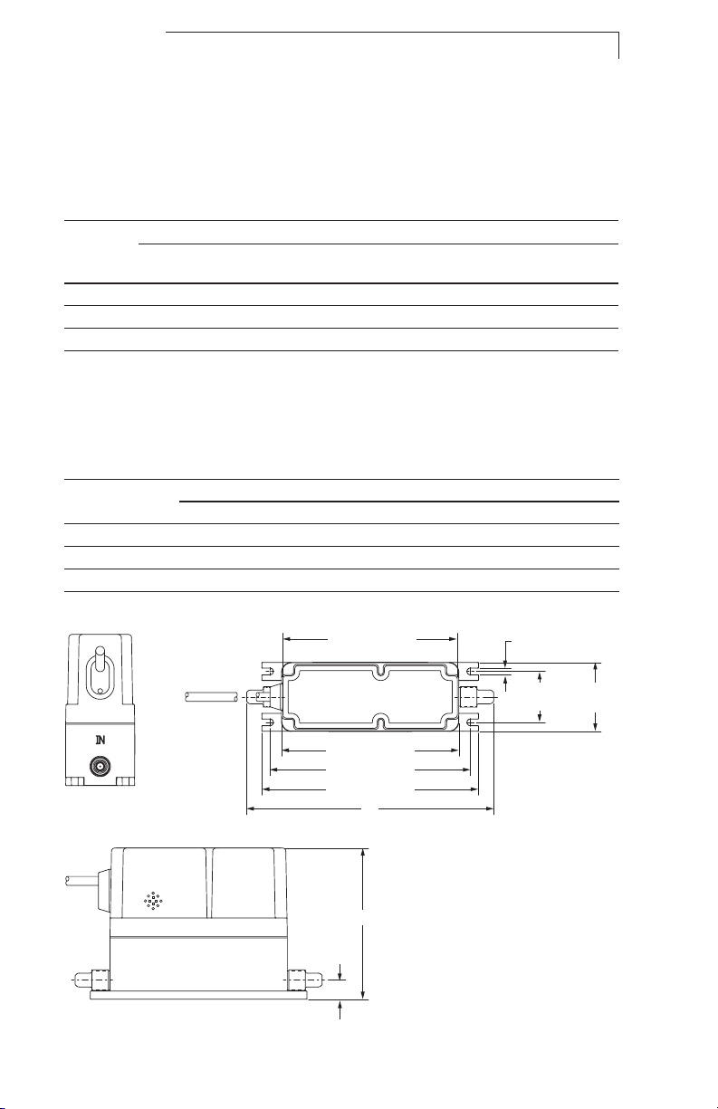
Dimensions
NT6510
The following fitting size and flow range combinations
are available (Flaretek® and Pillar® unless otherwise noted):
Flow Range (mL/min)
TL
Fitting Size
1
⁄4” Yes Yes Yes Yes Yes Yes Yes
3
⁄8” Yes Yes Yes Yes Yes Yes Yes
1
⁄2” — — — — — Yes* Yes*
0–15
* Flaretek® only.
Note: The operating range for "T" code flow ranges (default) is 10 –100% of full scale flow.
The operating range for "Y" code flow ranges is 5 –100% of full scale flow.
Please consult Entegris for PrimeLock® tube fitting options and custom flow range.
Flaretek Tube Fittings
Inlet/Outlet
Port Connection
1
⁄4” 117.9 mm (4.64") 17.0 mm (0.67") 187.5 mm (7.38”)
3
⁄8” 117.9 mm (4.64") 17.0 mm (0.67") 191.0 mm (7.52”)
1
⁄2” 120.8 mm (4.76”) 17.0 mm (0.67") 195.1 mm (7.68”)
TT
0–25
T0/Y0
0–50
T1/Y1
0–125
T2/Y2
0–250
Dimensions
A B C
T3/Y3
0–500
T4/Y4
0–125 0
End View Top View
134.9 mm (5.31”)
137.2 mm (5.40”)
154.9 mm (6.10” )
167.6 mm (6.60”)
C
5.1 mm
(0.20”)
39.4 mm
(1.55”)
53.2 mm
(2.10”)
Side View
A
B
ENTEGRIS, INC. USER GUIDE 5
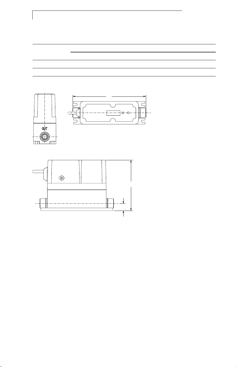
INVUE INTEGRATED FLOW CONTROLLERS, MODELS NT6510, NT6520
End View Top View
Super 300 Type Pillar Tube Fittings
Inlet/Outlet
Port Connection
1
⁄4” 117.9 mm (4.64”) 17.0 mm (0.67”) 159.3 mm (6.27")
3
⁄8” 117.9 mm (4.64”) 17.0 mm (0.67”) 167.1 mm (6.58")
A B C
C
Dimensions
Side View
A
B
6 USER GUIDE ENTEGRIS, INC.

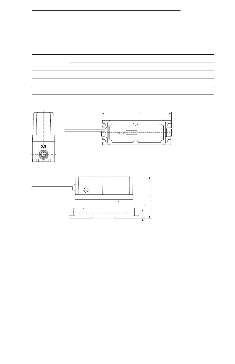
INVUE INTEGRATED FLOW CONTROLLERS, MODELS NT6510, NT6520
NT6520
The following fitting size and flow range combinations
are available (Flaretek and Pillar unless otherwise noted):
Flow Range (mL/min)
T5/Y5
Fitting Size
3
⁄8”
1
⁄2”
3
⁄4”
0–2.5
Yes Yes — — —
Yes Yes Yes — —
— — — Yes Yes
Note: The operating range for "T" code flow ranges (default) is 10 –100% of full scale flow.
The operating range for "Y" code flow ranges is 5 –100% of full scale flow.
Please consult Entegris for PrimeLock tube fitting options and custom flow range.
T6/Y6
0–5
T7/Y7
0–10
T8/Y8
0–20
Flaretek Tube Fittings
T9/Y9
0–40
Inlet/Outlet
Port Connection
3
⁄8” 117.3 mm (4.62”) 15.7 mm (0.62” ) 224.0 mm (8.82”)
1
⁄2” 120.9 mm (4.76”) 18.3 mm (0.72”) 228.0 mm (8.98”)
3
⁄4” 129.0 mm (5.08”) 23.6 mm (0.93”) 234.2 mm (9.22”)
A B C
End View
7.1 mm
(0.28”)
7.1 mm
(0.28”)
Dimensions
Top View
170.2 mm (6.70”)
187.5 mm (7.38”)
200.2 mm (7.88”)
Side View
A
B
C
47 mm
(1.85”)
71.1 mm
(2.80”)
ENTEGRIS, INC. USER GUIDE 7
INVUE INTEGRATED FLOW CONTROLLERS, MODELS NT6510, NT6520
NT6520
Super 300 Type Pillar Tube Fittings
Inlet/Outlet
Port Connection
3
⁄8” 117.3 mm (4.62”) 15.7 mm (0.62” ) 200.2 mm (7.88”)
1
⁄2” 120.9 mm (4.76”) 18.3 mm (0.72”) 205.2 mm (8.08”)
3
⁄4” 129.0 mm (5.08”) 23.6 mm (0.93”) 214.1 mm (8.43”)
A B C
End View
Dimensions
Top View
C
Side View
A
B
8 USER GUIDE ENTEGRIS, INC.
INVUE INTEGRATED FLOW CONTROLLERS, MODELS NT6510, NT6520
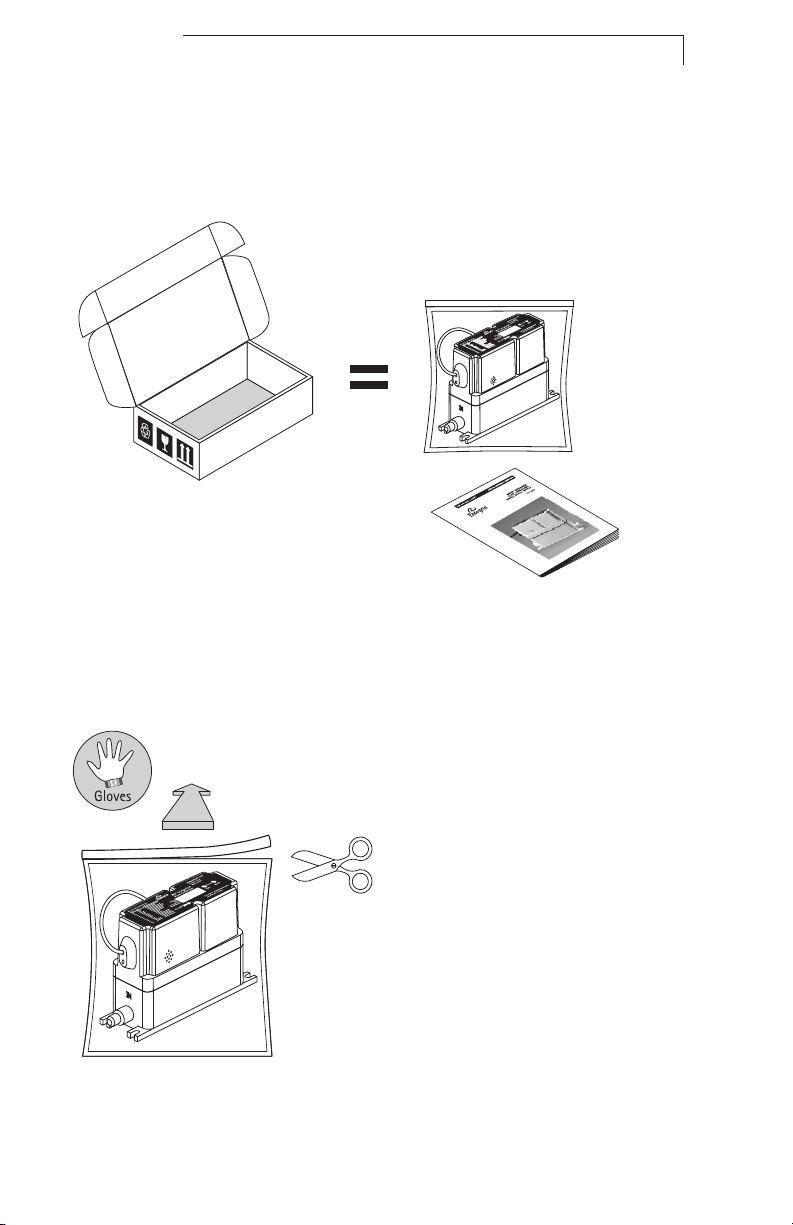
Installation
Provided Equipment
Verify:
CAUTION: Do not tighten the
!
nuts that protect the tube
connections during shipment.
(See the Prepare Fluid Lines
Section on page 9). Tightening
these nuts without the proper
tubing installed may damage
the unit’s tube connections.
NOTE: This unit has been assembled
and double-bagged under cleanroom
conditions. To maintain purity, only
open under cleanroom conditions.
Remove Unit from the Bag
ENTEGRIS, INC. USER GUIDE 9
 Loading...