

Page 1
Save the user manual for future reference.
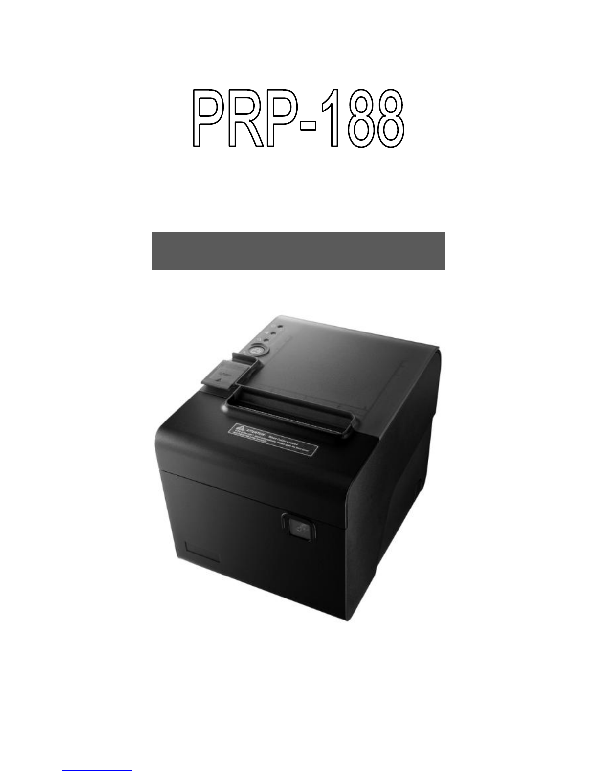
Thermal Receipt Printer
Instruction Manual
Page 2

Page 3

Table of Contents
A. IMPORTANT SAFETY NOTIFICATION ............... 1
B. PRODUCT OVERVIEW ....................................... 3
Main Features .................................................................. 3
Packing ............................................................................ 4
Specification ..................................................................... 5
Part Description ............................................................... 7
DIP Switch Configuration ............................................... 14
C. INSTALLING YOUR PRINTER .......................... 16
Connecting Your Printer ................................................. 16
Vertical Printing Installation ............................................ 17
Install/Replace the Paper Roll........................................ 18
Installing the Driver of Your Printer ................................ 20
Printer Configuration ...................................................... 24
D. APPENDIX......................................................... 30
1. Cutter Maintenance .............................................. 30
2. Interface PIN Assignment ..................................... 32
3. Self Test ................................................................ 35
4. Virtual Serial Port Installation
(for USB Connection Only).................................. 36
5. Ethernet Connection and Configuration ............... 45
6. Code Page Setup ................................................. 62
Page 4

Page 5

- 1 -
A. Important Safety Notification
Read the instruction manual carefully before use.
Save the manual in the near location for further
reference.
Use only parts or accessories, especially power adapter,
recommended by the manufacturer; unapproved parts
may be hazardous and cause injures to the product or
human.
WARNING:
IF ANY FUNCTIONAL PROBLEMS OR DEFECTS
OCCUR WHICH ARE ATTRIBUTABLE TO
IMPROPER USE OF THE PRODUCT SHALL
VOID THE WARRANTY.
Refer servicing to qualified personnel only.
Do not attempt to repair or dissemble the product on
your own. Opening or removing cover can expose you
to dangerous voltage or other hazards.
Before plugging the power cord into the AC inlet of the
power supply unit, make sure that the voltage applied to
the power outlet is within the specified range
(100V ~240V). Improper power source voltage range
will cause damage to the power supply unit.
Power off the product and remove the power adapter
while cleaning the system.
Before powering on the product, make sure all the
connectors, cables are firmly installed.
Page 6

- 2 -
Important Safety Notification
Do not expose the product to rain or moisture, such as a
bathtub, a washbowl, a kitchen sink, a laundry tub, and
a swimming pool.
Do not expose the machine under direct sunlight, and
keep it away from any heat source.
Do not place the product on an unstable location, stand
or table. If the machine falls, it may injure a person or
cause serious damage to the appliance.
Do not allow anything to rest on the power cord.
Do not locate the product where people may walk on the
cord.
Do not make the power outlet and extension cords
overload. Overload can result in fire or electric shock.
If any of the following situations occurs, unplug the
product from the power outlet immediately and consult
with a qualified service person:
1. The power cord or plug is damaged or frayed.
2. Liquid is spilled into the system.
3. The product is dropped and damaged.
Use a soft cloth to clean the product when it is dirty. In
case the dirt is hard to remove, use a mild detergent and
wipe the product gently.
Turn OFF and unplug the product before cleaning.
When the product is not in use, clean and stores it with
care.
Page 7
- 3 -
B. Product Overview
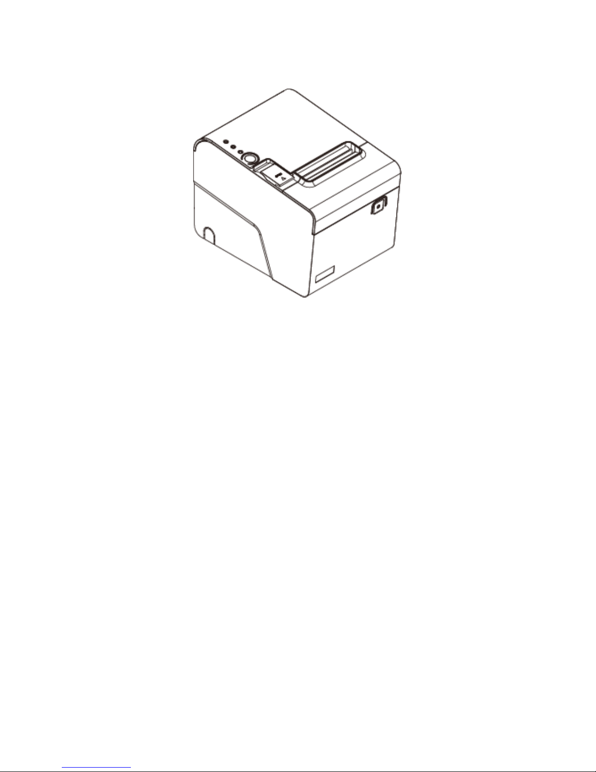
Main Features
Splash and dust proof design
Paper Auto-Cutter
Vertical printing
Multi I/O Interface (Serial +Ethernet +USB or Parallel
+USB)
Cash drawer connection port (RJ-11)
Compatible with ESC/POS print commands set
Various Drivers available
User friendly, drop-and-print paper installation, simple
paper jam elimination
Optional audible indicator version good for noisy
environment operation
Multiple Language fonts selectable
Ethernet Connection Web Page Configuration
DHCP Clint support
Page 8
- 4 -
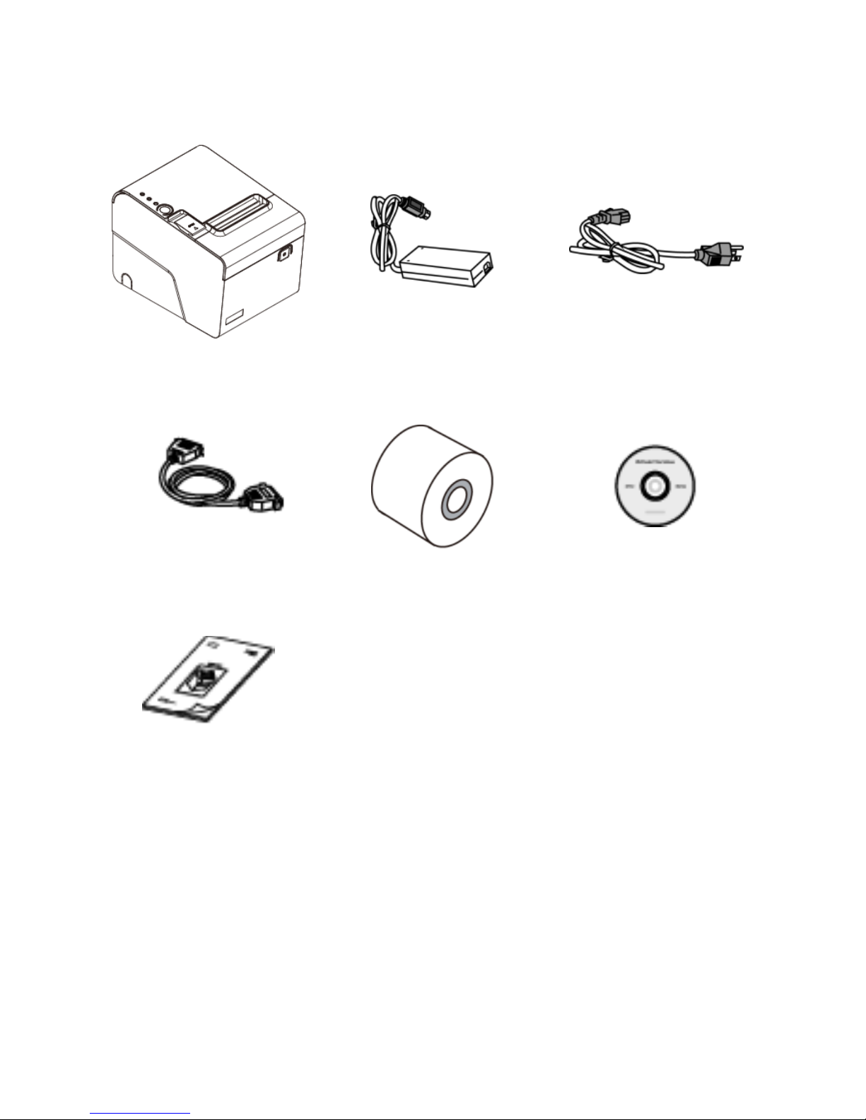
Packing
Printer Unit
Power Adaptor
*Power Cord
**Printer Cable
Paper Roll
Utility CD
Manual
* Power Cord is selectable depending on the types of electrical plug.
** Printer cable is selectable depending on the interface required
(RS-232, USB, RJ-45 or RJ-11).
Please refer to the nearest local representatives for further
information.
Page 9
- 5 -
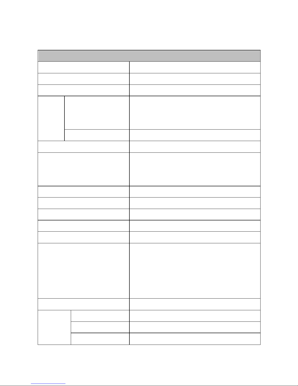
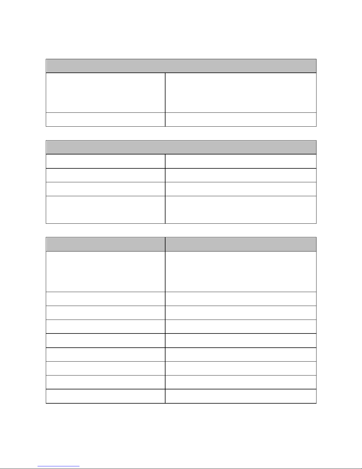
Specification
General
Print Method
Thermal line printing
Print Speed
250mm/sec
Print Life
100 Km
Print
Font
(ASCII Mode)
ANK Font.
Font A: 12 x 24 dots,
Font B: 9 x 17 dots
Graphic Font)
Chinese Character: 24 x 24 dots
Print Resolution
576 dots/line or 512 dots/line
Print Font Character
Support *
International Font, Big 5 Chinese,
GB Chinese, Japanese,
Korean selectable
Character Per Line
48 (Font A) / 64(Font B)
Effective Print Width
72mm
Paper Width
79.5mm± 0.5mm
Paper Roll Diameter
≦83mm
Paper Thickness
0.06~0.08mm
Driver
Win 9X/Win ME/Win 2000/
Win 2003/Win NT/Win XP/
Win Vista/Win 7, Win 8
compatible with EPSON and
SAMSUNG
Print Command
ESC/POS print commands set
Buffer
Receipt
128K bytes
User-Defined
128K bytes
NV Flash
256K bytes
* All specifications are subject to change without prior notice.
Page 10
- 6 -
Interface
I/O Interface
Multi I/O Interface
(Serial +Ethernet +USB or
Parallel type selectable)
Cash Drawer
DC 24V/1A, 6-Wire RJ-11
Notification
Indicator
Audio and LED Indicators
Auto Cutter
Partial
Paper End Notice
Yes
Over-Heat
Halt-on Protection
Yes
Others
Power Input
24VDC/2.5A
(External Adapter:
100~240VAC 50/60Hz)
Color
Black
Compliance
FCC / CE / WEEE / RoHS
Weight
1600g (without cable )
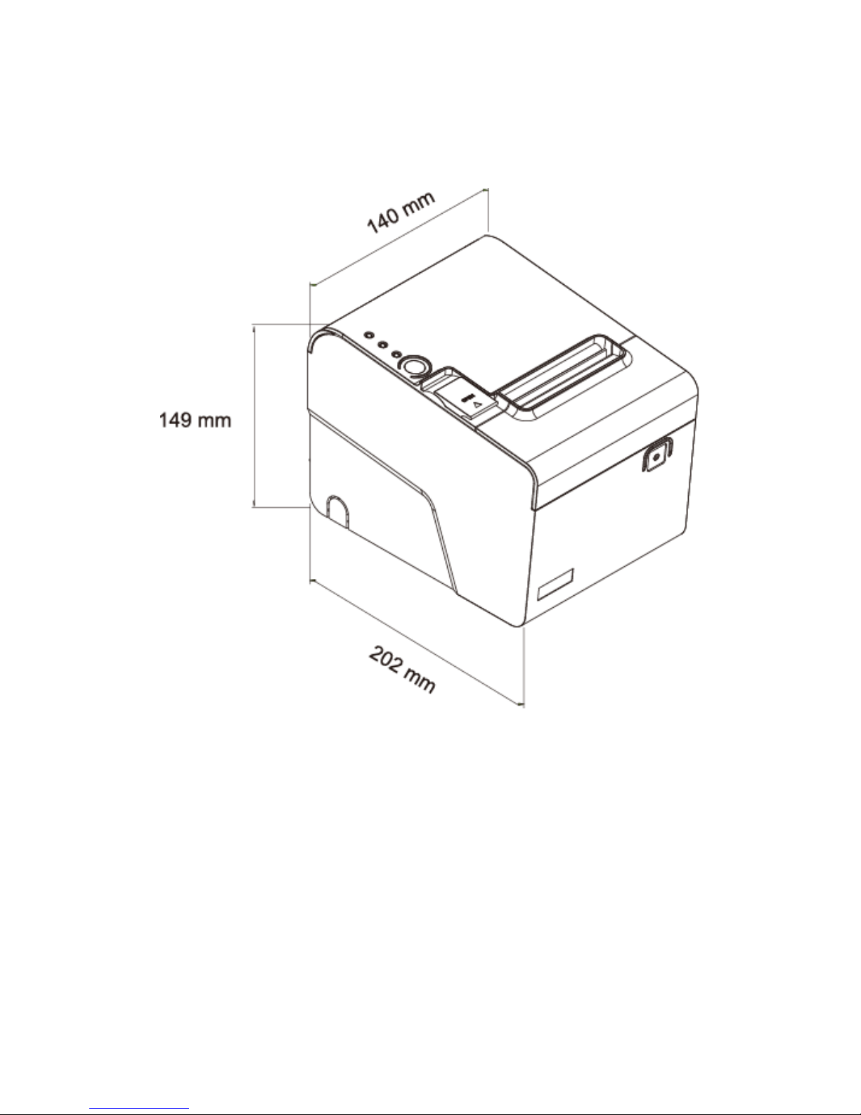
Dimension (mm)
202(L) x 140(W) x 149(H)
Operating Temperature
0°C~45°C
Operating Humidity
10% ~ 80% RH, non-condensing
Storage Temperature
-10°C~ 60°C
Storage Humidity
10% ~ 90% RH non-condensing
* All specifications are subject to change without prior notice.
Page 11
- 7 -
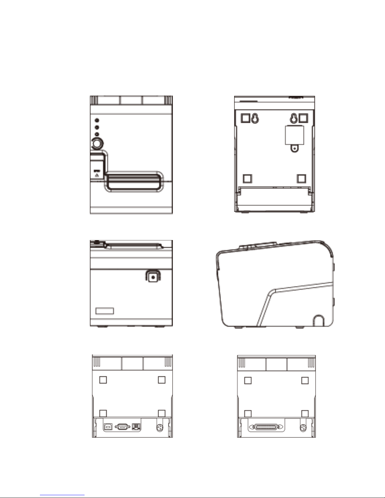
Part Description
Product Views
Top View
Bottom View
Front View
Side View
Rear View (Serial/USB)
Rear View (Parallel)
Page 12
- 8 -
Dimensions
Page 13
- 9 -
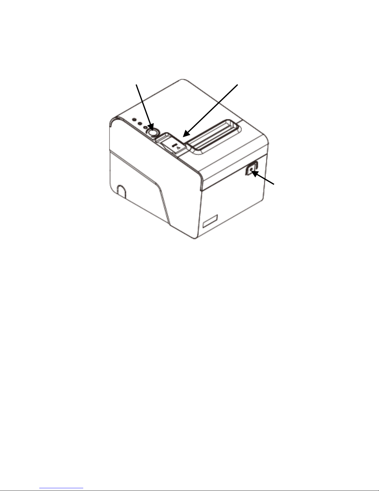
Control buttons & Indicators
Paper Feed:
This function is to advance the paper.
Press the key and the paper advances by a single line.
Press and hold the key for over 3 seconds and the paper
advances by multiple lines.
Cover Release Button:
Push the button to the right to open the printer cover.
Power
Switch
Cover Release Button
Paper Feed Button
Page 14
- 10 -
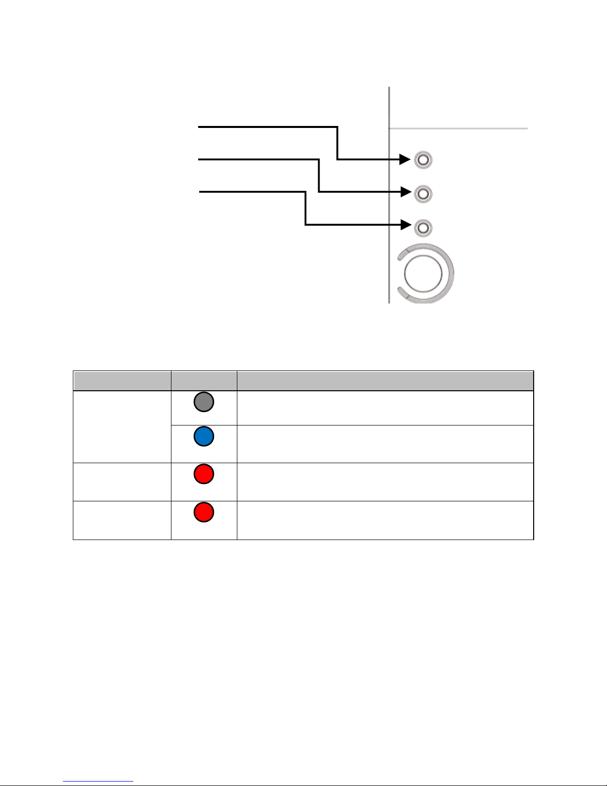
Indicator Status
Indicator
Status
Description
Power
Power Off
Power On
Error
Printer Error (Out of paper, Printer
head over heat, or paper cutter error)
Paper
Out of paper
* The Error Indicator is lit as well
Power Indicator
Error Indicator
Paper Indicator
Page 15
- 11 -
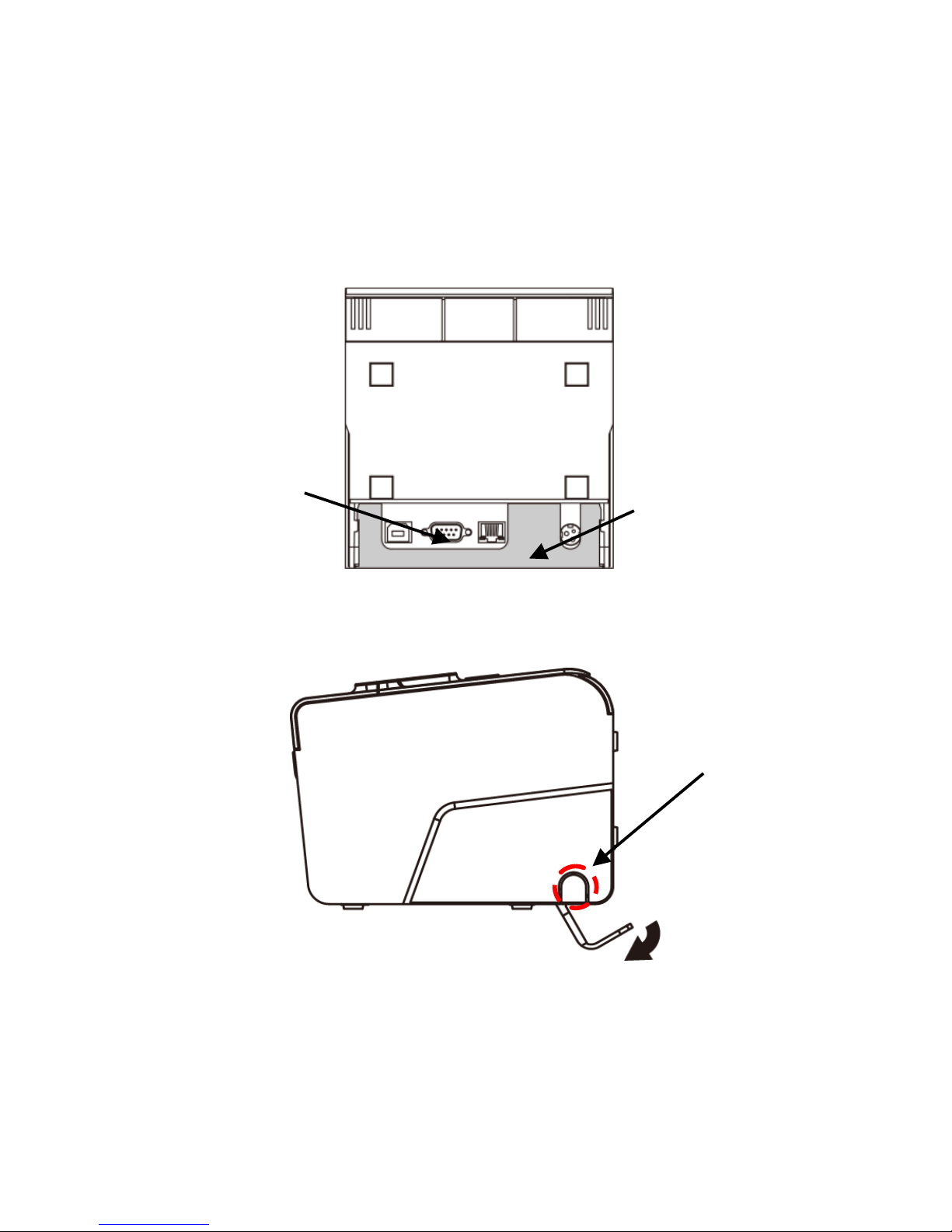
I/O Ports & Cables
When plug the cables to the printer, pull the I/O Port Bracket
beforehand so as to secure connectors easily.
Open the side cable pass-through opening if necessary.
Rear View
Side View
Note:
Remember to re-install the I/O Port Bracket to the printer as
the connectors are properly secured.
I/O Port Bracket
Multi-I/O Ports
I/O Port Bracket
Side Cable
Pass-Through
Opening
Page 16
- 12 -
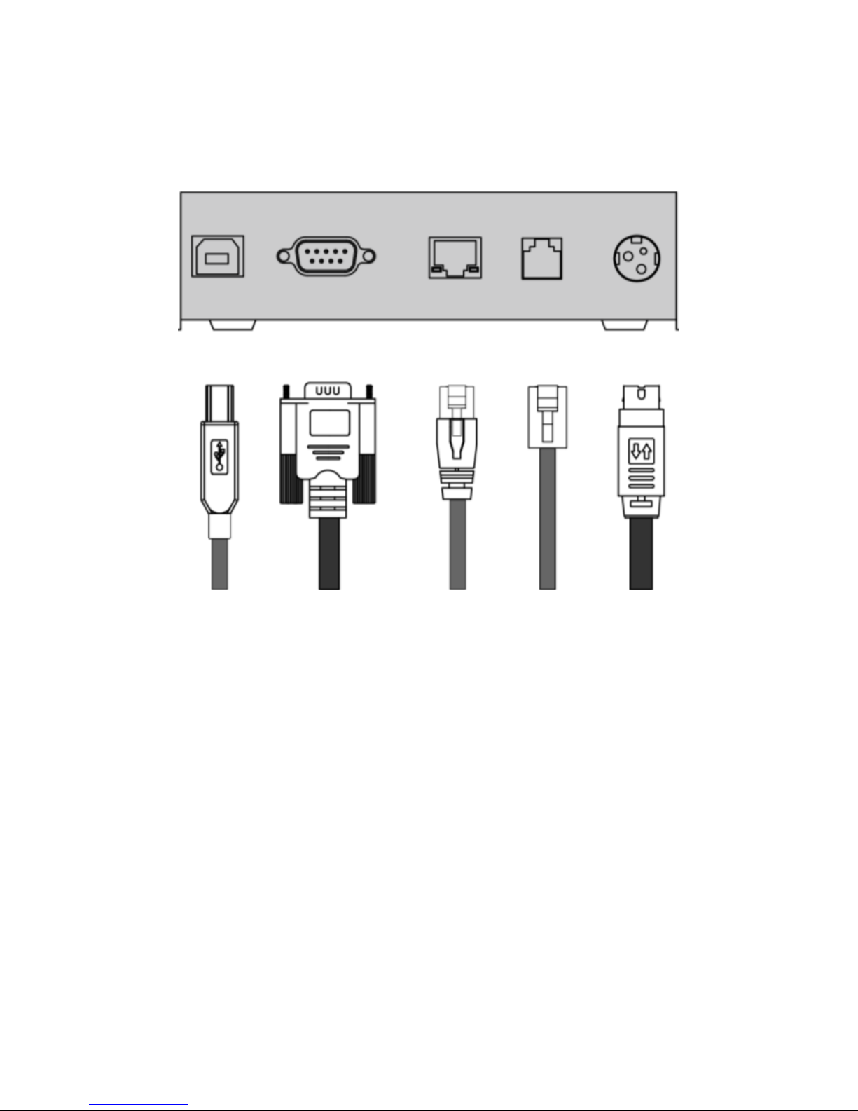
Multi-I/O Ports
RS-232/USB Type
* Printer cable is selectable depending on the interface required
Please use the supplied printer cable or purchase it separately
*Printer Cable
Cash
Drawer
Power
Adaptor
USB RS-232 RJ-45 RJ-11 PWR
Page 17
- 13 -
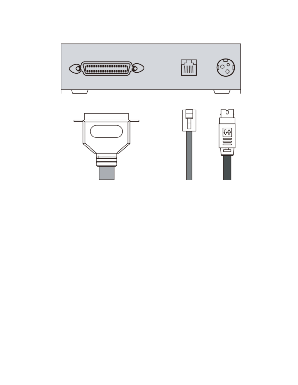
Parallel Type
Parallel Port RJ-11 PWR
Printer Cable
Cash
Drawer
Power
Adaptor
Page 18
- 14 -
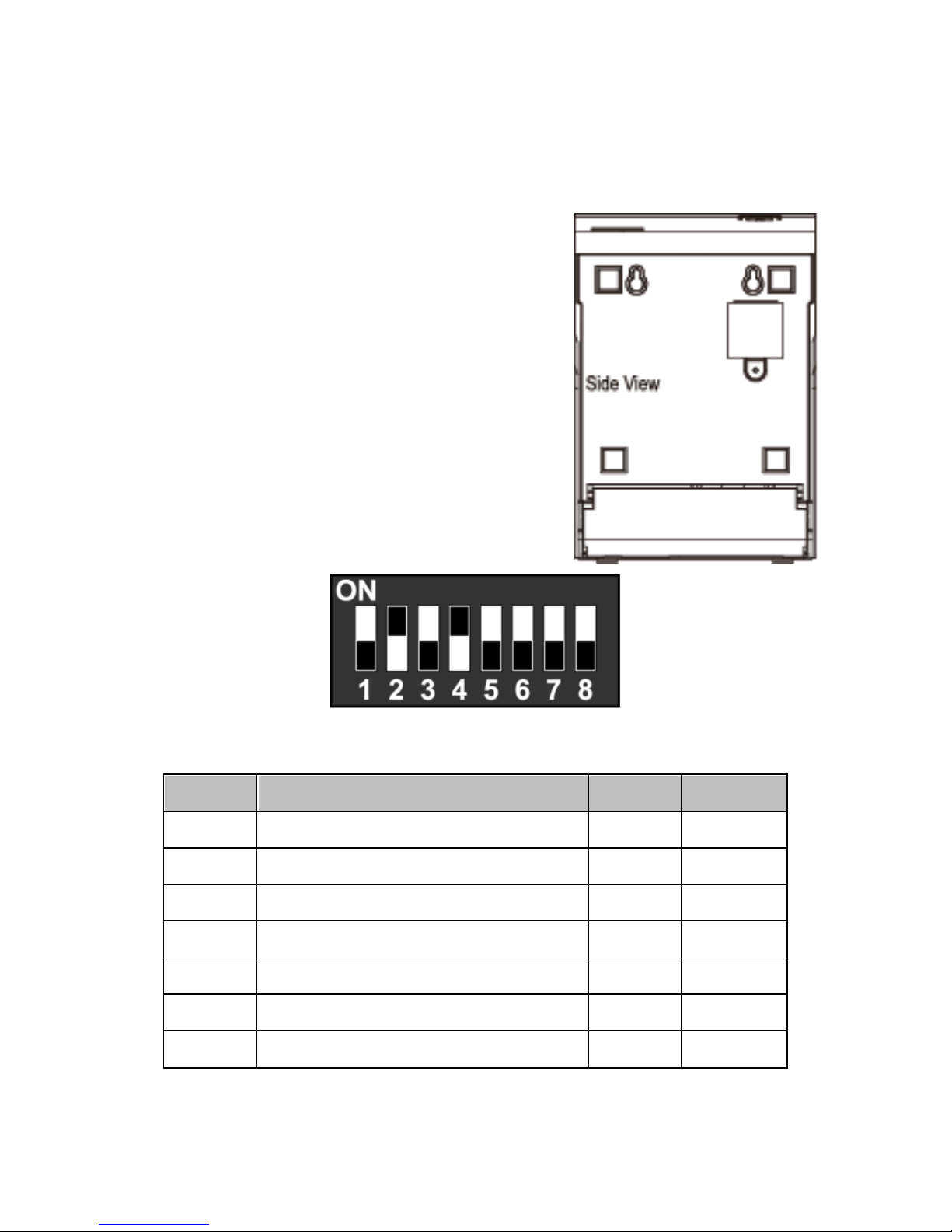
DIP Switch Configuration
To change the setting of the printer manually:
1. Turn off the printer.
2. Remove the protective cover
of the DIP Switches.
3. Turn On or off the switches to
configure the printer.
DIP Switch Setting
DIP
Function
ON
OFF
1
Paper Cutter
No
Yes*
2
Audio Alarm
Yes *
No 3 Print Density
Dark
Light *
4
Two-byte Character Code
*No
Yes
5
Character Per Line
42
48 *
6
Cutter with Cash Drawer
Yes
No *
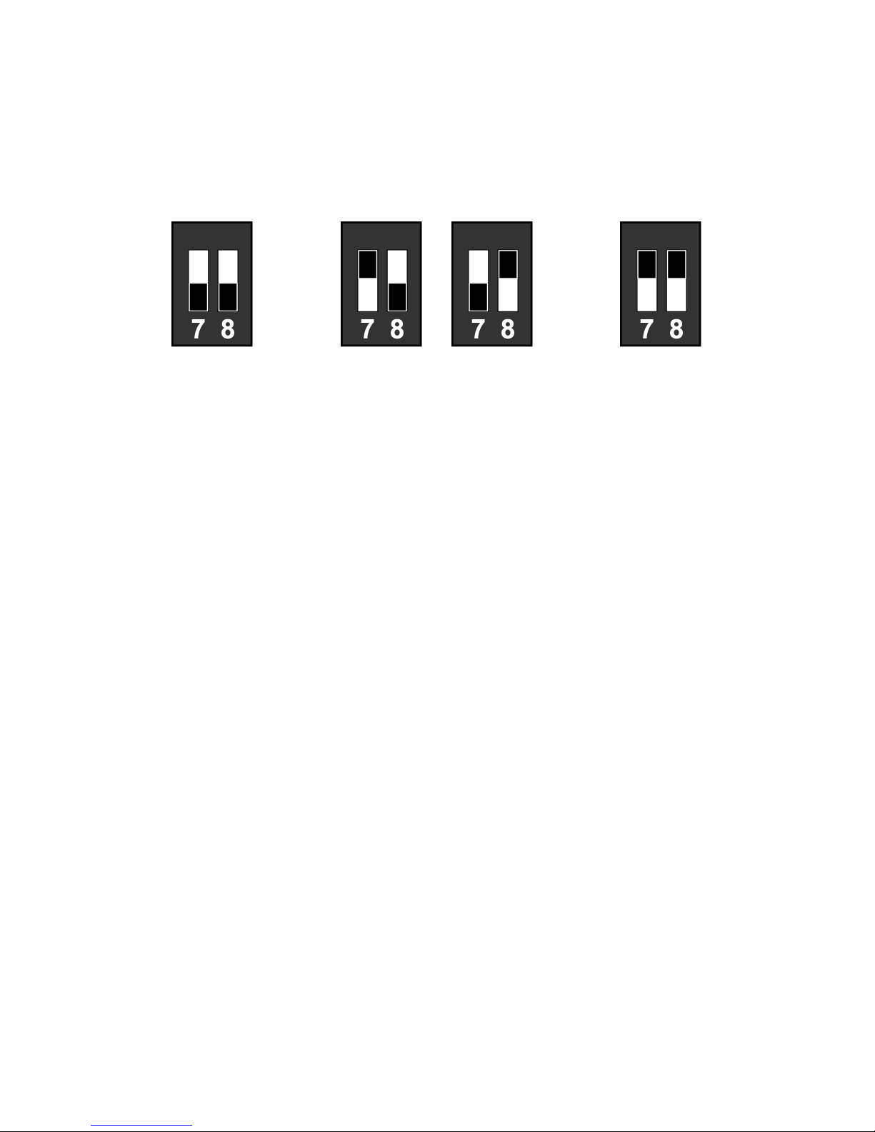
7 & 8
Baud Rate Setting
---
OFF*
The “*” mark indicates the default value of each setting.
Protective
Cover
Configuration DIP Switches
Page 19
- 15 -
Baud Rate Setting (DIP 7, DIP 8)
19200
(*Default)
9600
115200 38400
Page 20
- 16 -
C. Installing your Printer
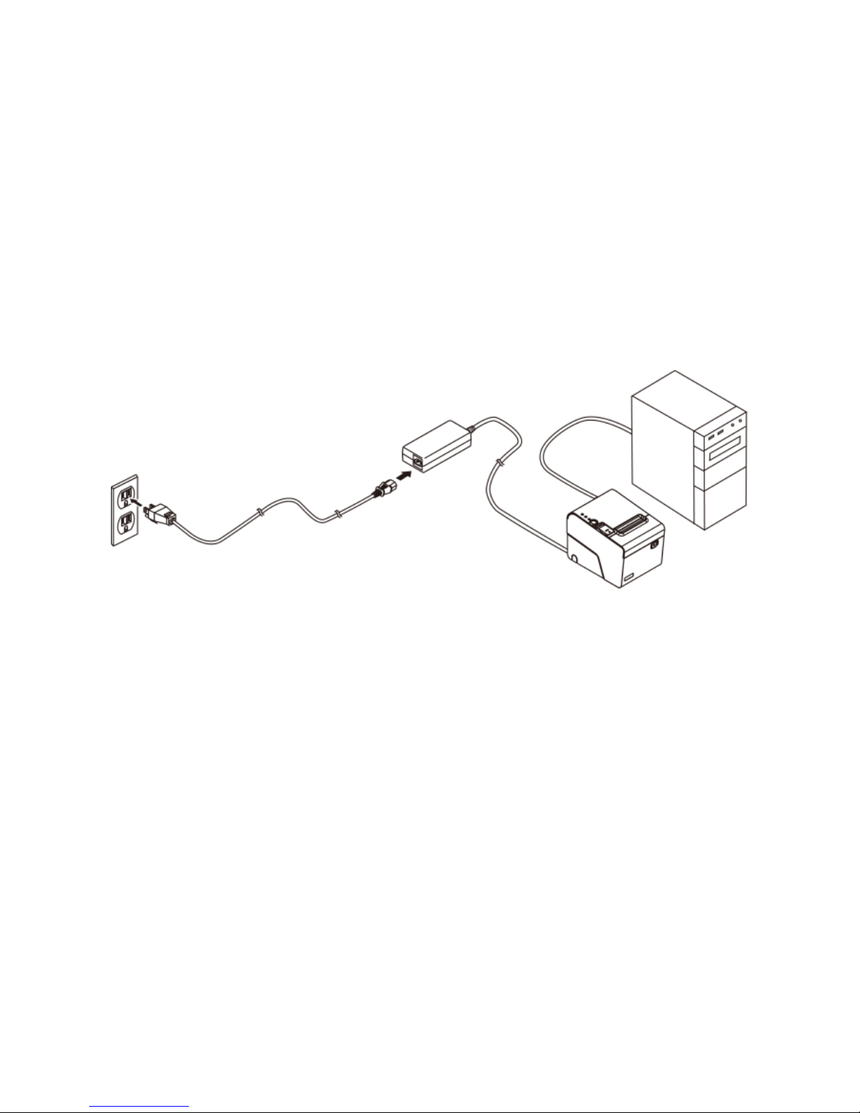
Connecting Your Printer
Please check the printer and the supplied accessories
before Installation. It’s recommended to read the entire
instruction manual prior to the installation.
1. Place the printer on the designate location.
2. Detach the I/O Port Bracket.
Plug the connector of Power Adaptor to the printer.
3. Use the supplied Printer Cable (RS-232, Serial, USB
or RJ-45) and connect to the Host PC.
4. Plug the Power Cord to the Power Adaptor and then
plug to the power outlet.
5. If there is a Cash Drawer to be connected, connect the
RJ-11 cable to the printer.
6. Re-install the I/O Port Bracket.
Printer
Cable
Host PC
Printer
Power
Adaptor
Power Cord
Page 21
- 17 -
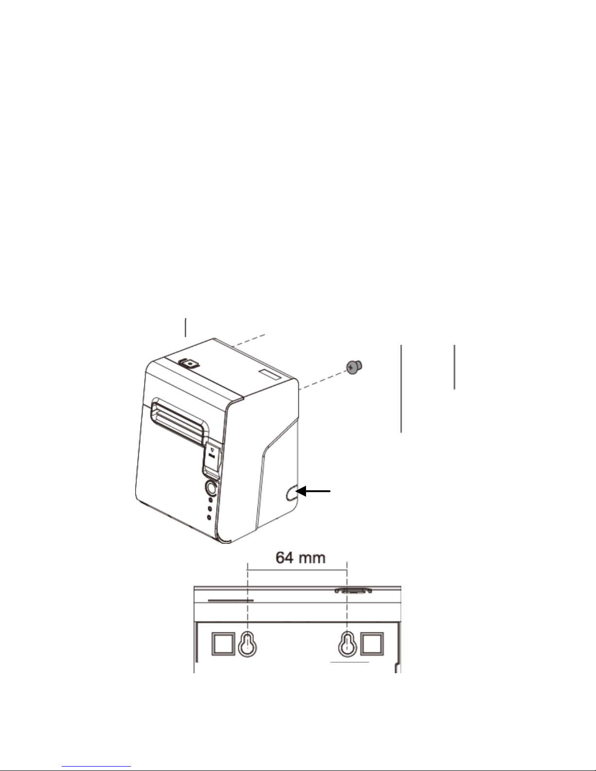
Vertical Printing Installation
You can install the printer onto a flat surface vertically and
perform printing tasks. It is convenient when the space is
important concerns:
1. Secure two mounting screws onto the location
(e.g. wall).
2. Connect the cables to the printer.
3. Place the printer on the location with the mounting holes
fitted on the screws.
Mounting Holes
Side Cable
Pass-Through Opening
Mounting Screws
Page 22
- 18 -
Install/Replace the Paper Roll
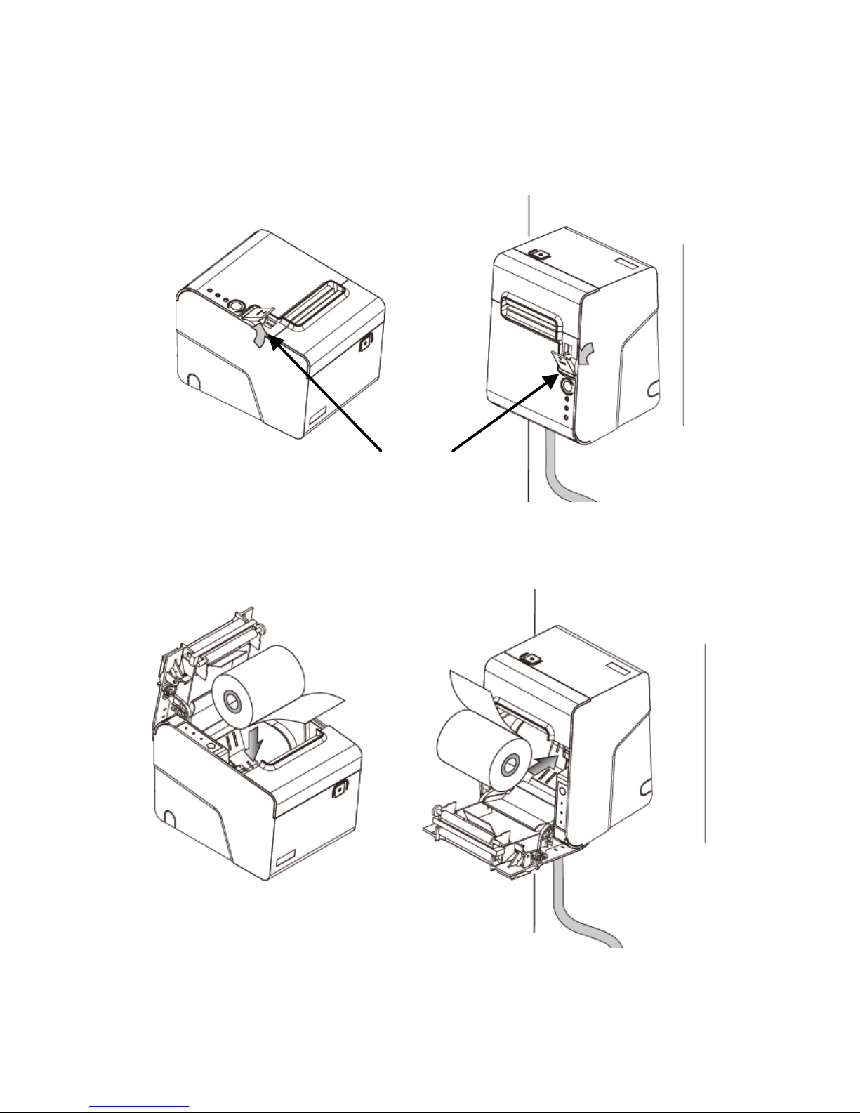
1. Pull the Cover Release Button to open the Cover.
2. Roll out and install the Paper Roll into the Printer.
Paper Roll
Cover Release Button
Page 23
- 19 -
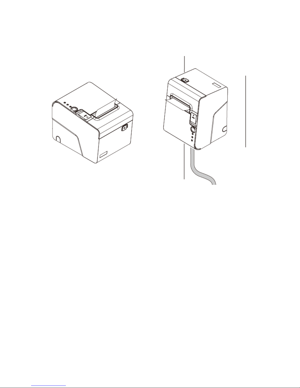
3. Replace the Cover and tear out the paper.
Page 24
- 20 -
Installing the Driver of Your Printer
Before installing the driver of your printer, make sure the
printer is properly connected to the host PC.
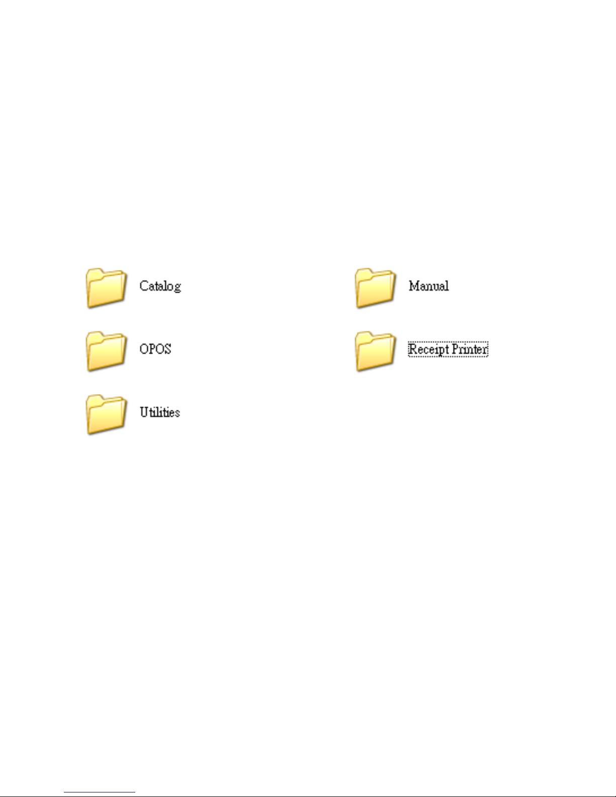
Place the supplied Utility CD into the CD-ROM drive.
Browse the CD and open the folder “Receipt Printer” to
install the required software.
Note: For USB Interface Installation
Please refer to “Appendix” and install the Virtual COM driver
(page 36) prior to the Installation of Printer Driver.
Page 25
- 21 -
To install the driver of the printer:
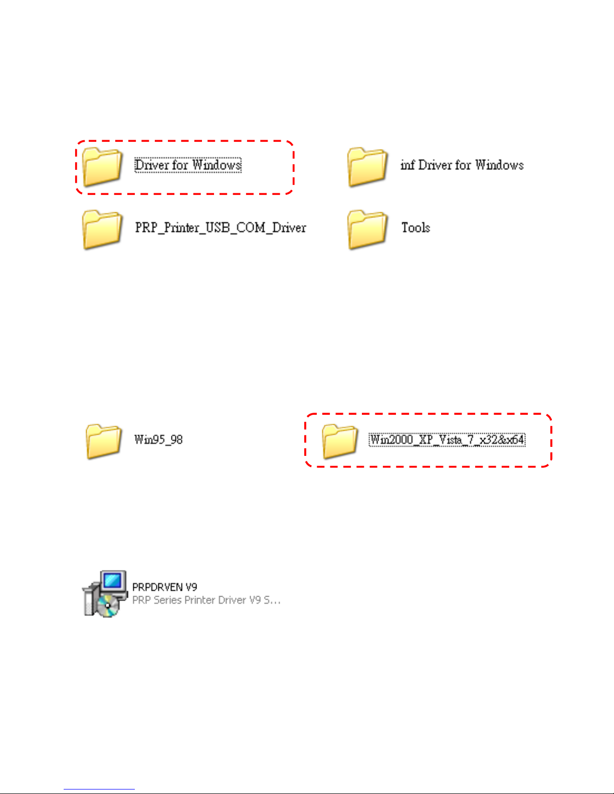
1. Select the folder “Driver for Windows”.
2. Select the subfolder to access the driver suitable for
the operating system.
(For example: select “Win2000_XP_Vista_7_x32&x64”
for Windows XP version).
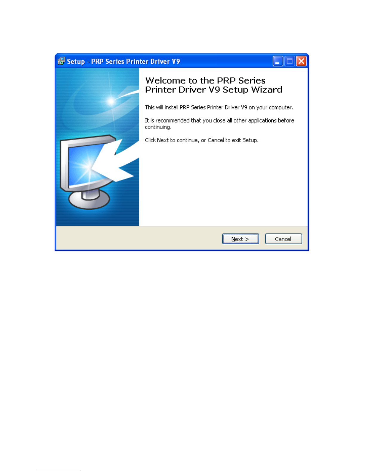
3. Double click the icon “PRPDRVEN V9.EXE” to initiate
the installation.
Page 26
- 22 -
4. Click “Next” to continue.
Page 27
- 23 -
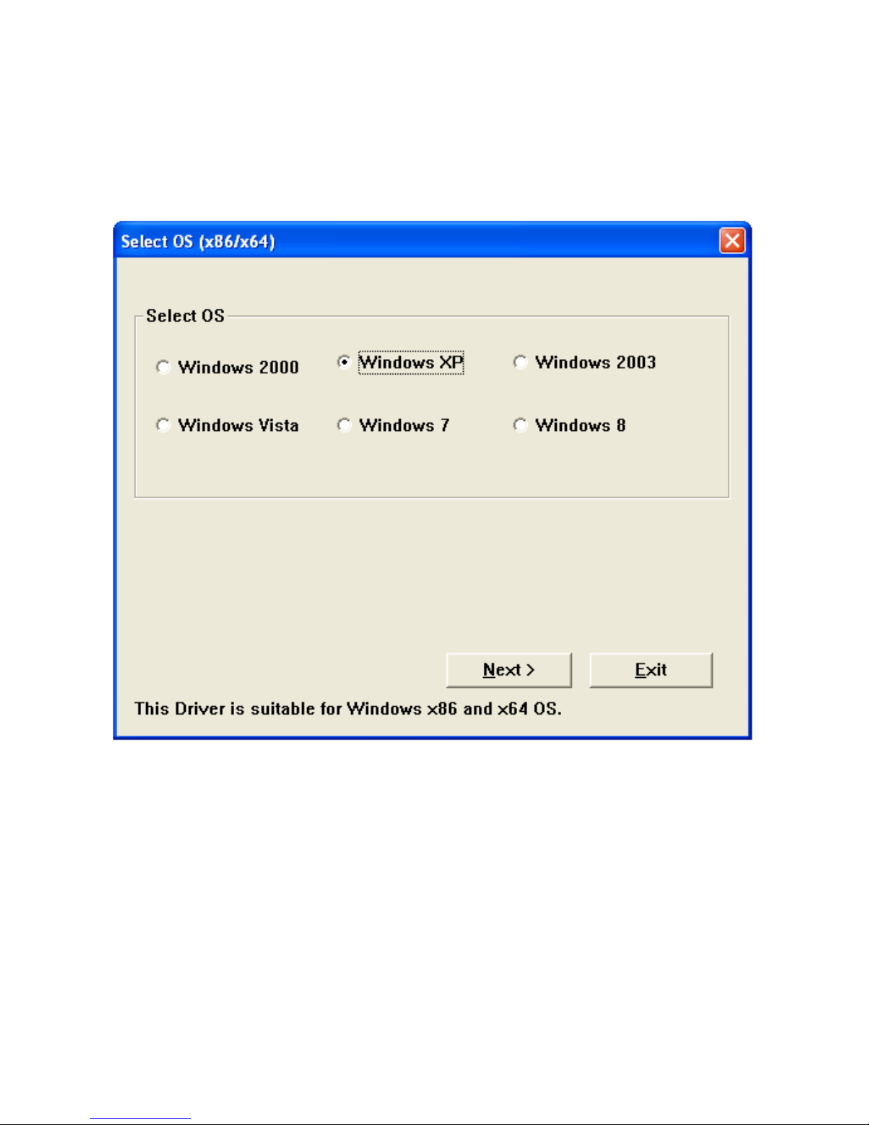
5. Select the Operating System.
(For example: select “Windows XP” for Windows XP
version). Click “Next” to continue.
Page 28
- 24 -
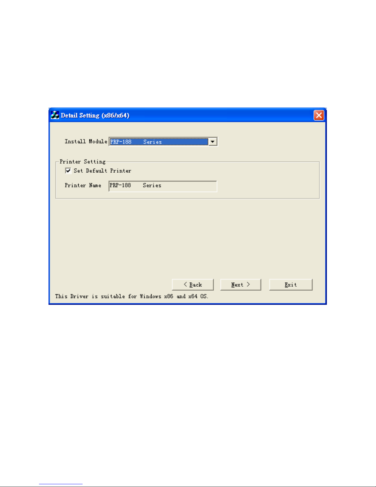
Printer Configuration
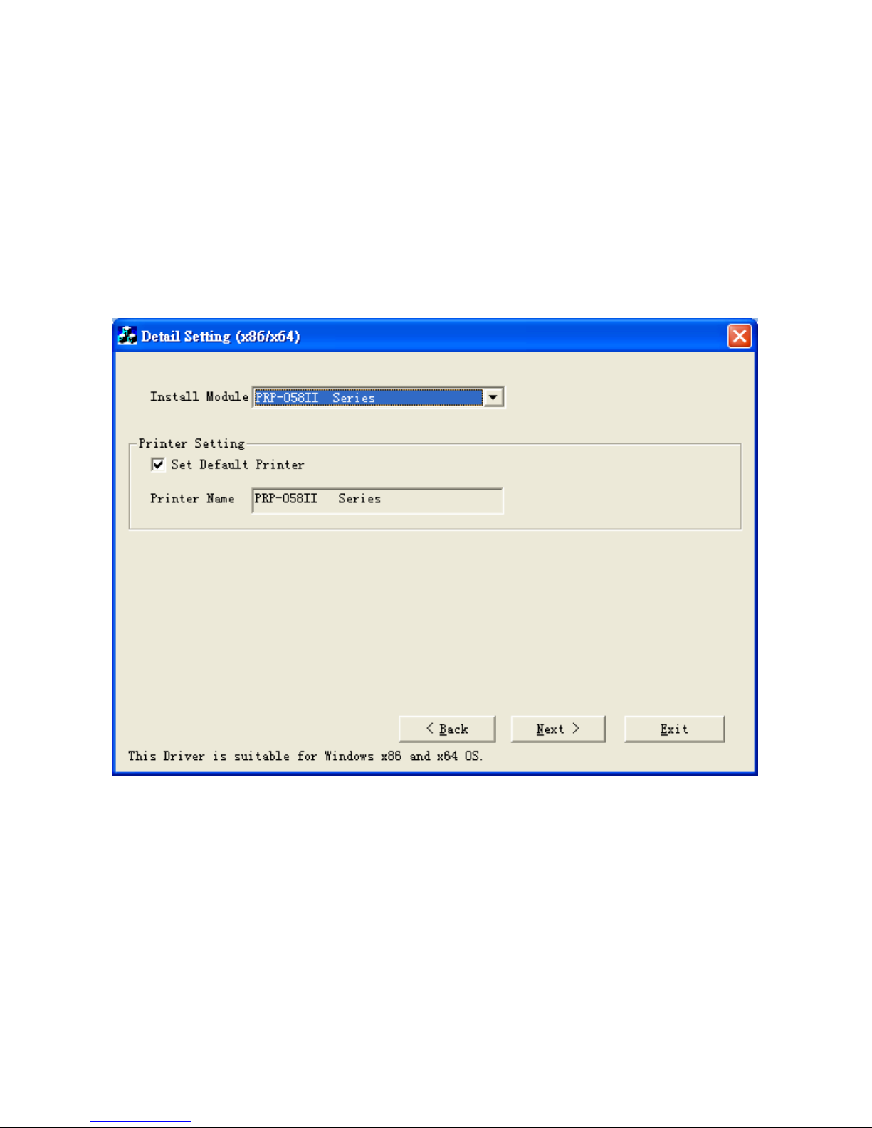
This menu allows user to configure the printer according to
the model number.
Please refer to the steps below to complete the
configuration.
Page 29
- 25 -
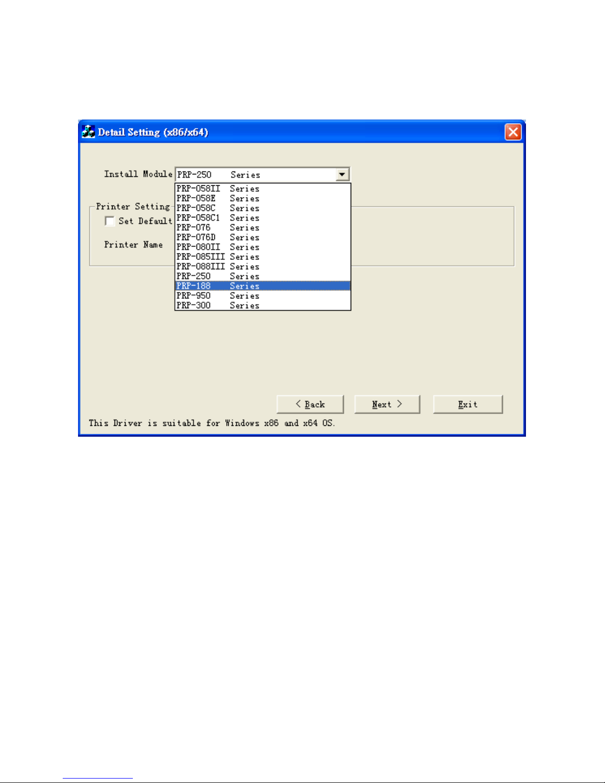
1. Select Module Number:
Select the proper Printer Model Number
Page 30
- 26 -
2. Default Printer Setting:
To set the printer as the default printer, click the
checkbox to confirm.
Click “Next” to continue.
Page 31
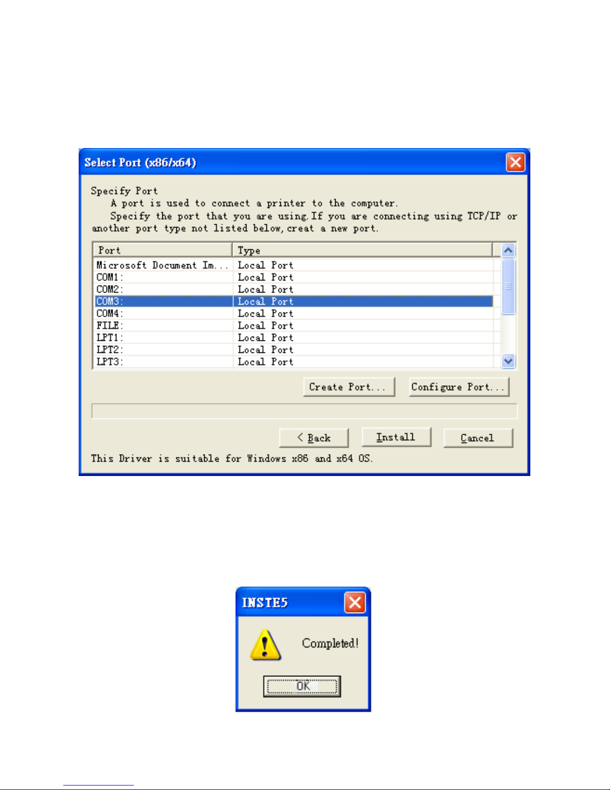
- 27 -
3. Printer Interface Setting:
Select the communication interface
(COM port number or LPT port number).
Click “Install” to complete the installation.
4. Configuration Completed.
Click “Finish” to exit the menu.
Page 32
- 28 -
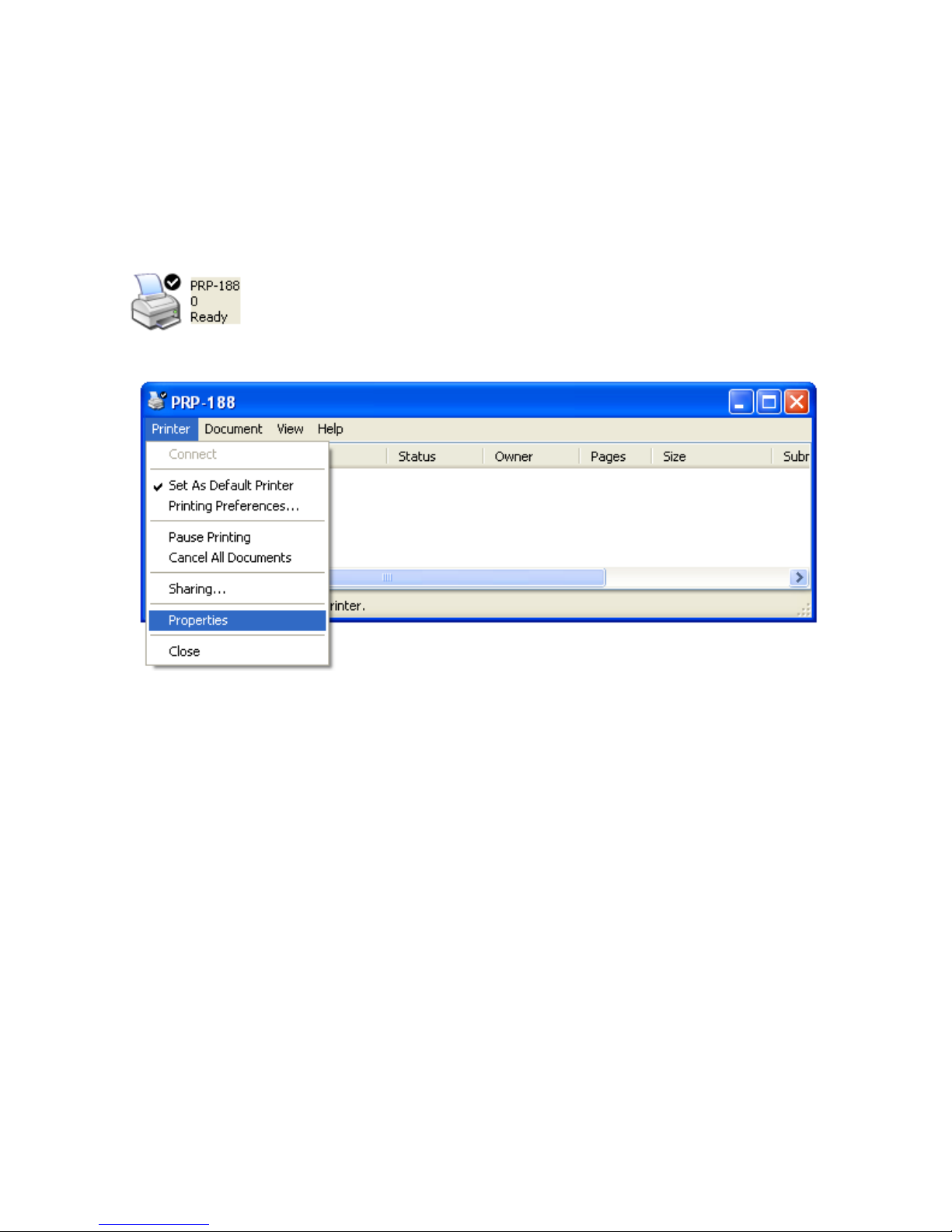
5. Port Setting:
Remember to access the properties of your printer
(Start>>Printers and Faxes>> and Double-click the
icon) to access the properties.
Make sure the port of printer is properly configured.
Page 33
- 29 -
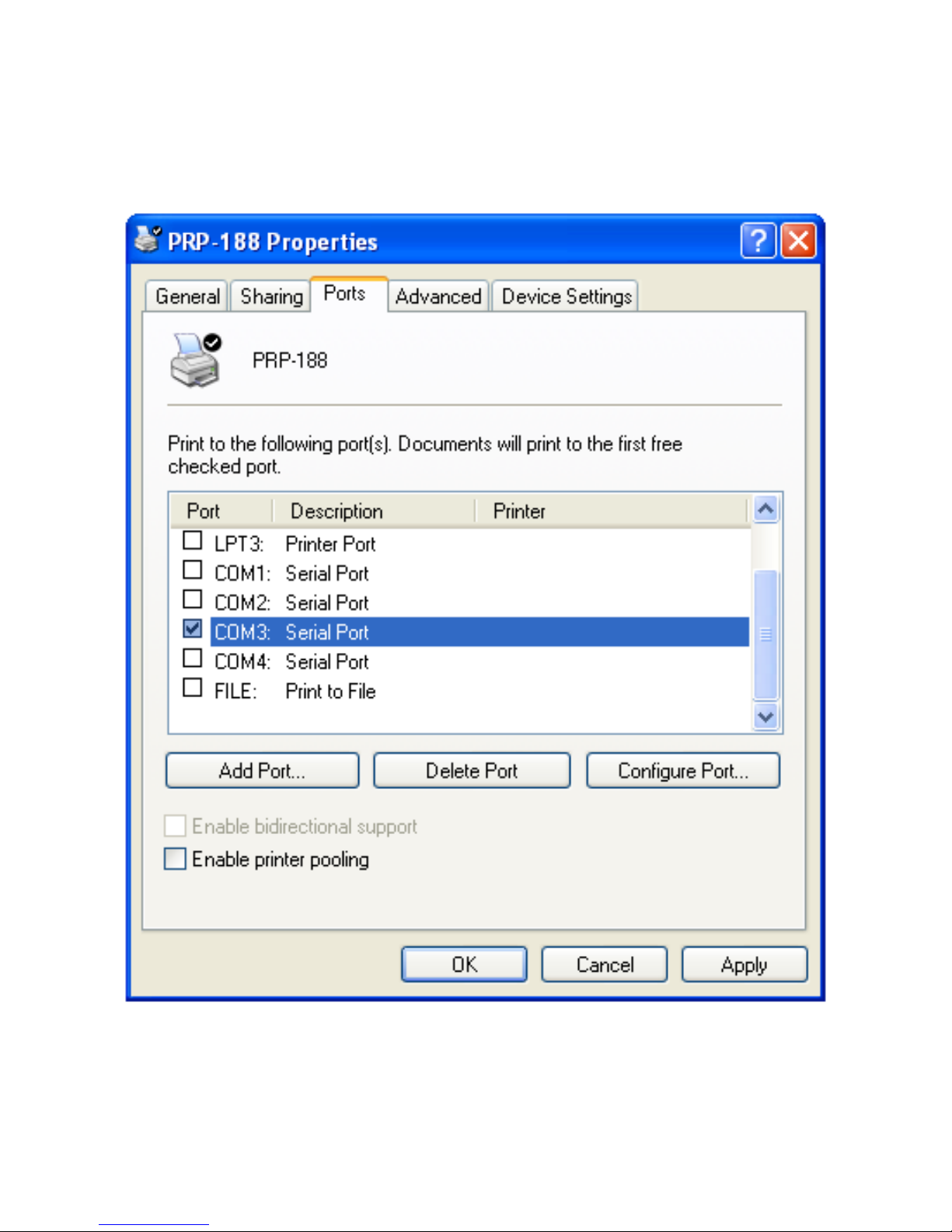
Access sub menu “Ports”, and click to select the correct port
for your printer.
Click “OK” to exit.
Page 34

- 30 -
D. Appendix
1. Cutter Maintenance
In general, the printer will initial and reset the cutter when
turn on the power. To reset the cutter back to the initial
position:
1. Turn off the printer.
2. Turn on the printer and the printer will initial and reset
the cutter.
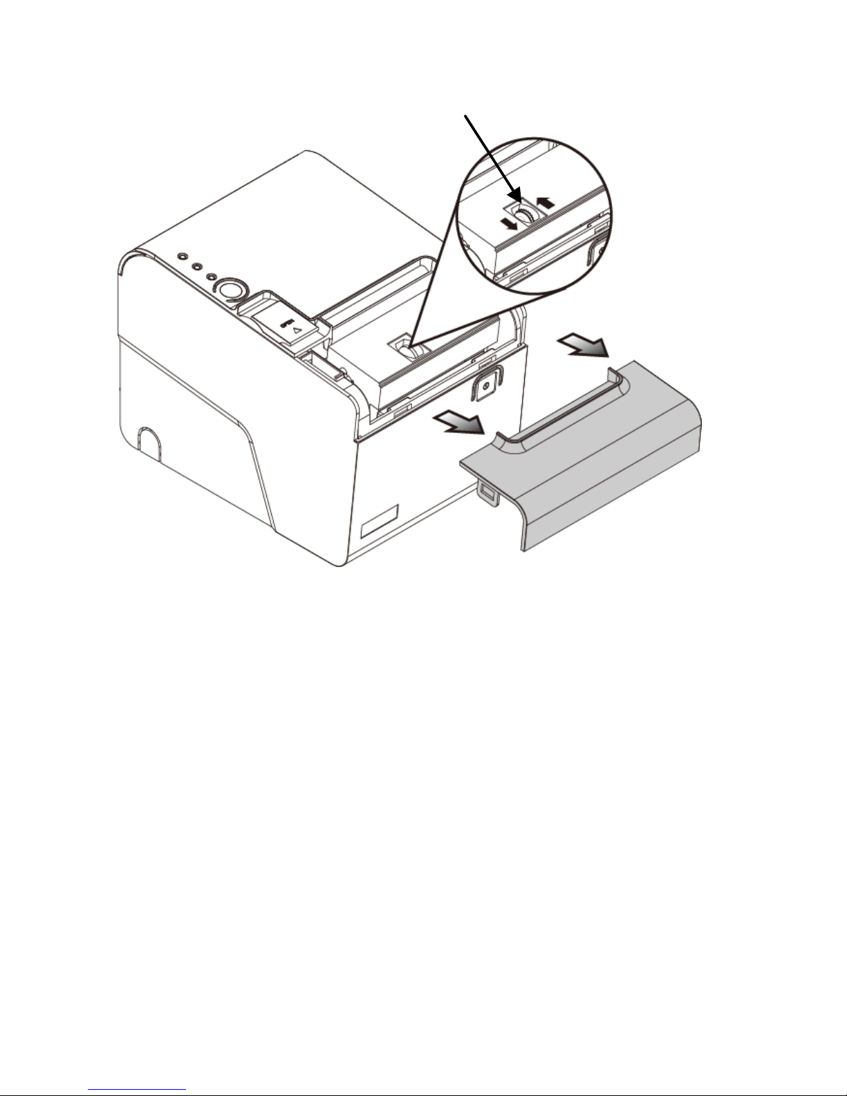
User can manually reset the cutter back to initial position
(as images illustrated):
1. Push the Cover Release Button to open the Cover.
Examine and remove the paper dust from the printer
by using a soft brush.
2. Push the Front Cover and remove it from the printer.
3. There is an Adjustment Gear in the cutter.
Turn the Adjustment Gear to move the cutter back to
the position.
Page 35
- 31 -
Note:
Do not remove the protective cover with force or it may
damage the cutter or printer head.
Warning:
Beware of the Cutting Edge of the cutter module during
maintenance in order to avoid injury to the person near the
printer.
Adjustment Gear
Front Cover
Page 36
- 32 -
2. Interface PIN Assignment
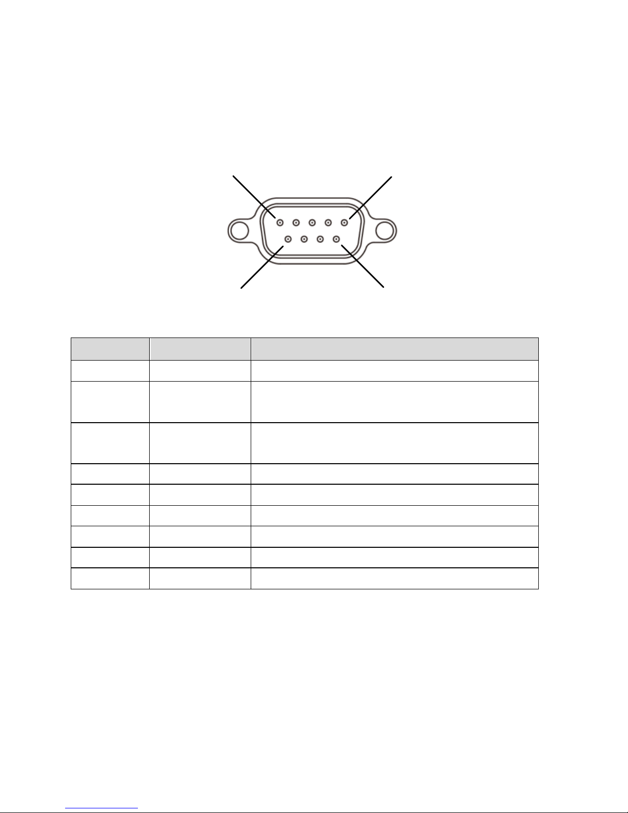
RS-232 Pin Assignment
Pin
Signal
Description
1
N.C.
---
2
TXD
XON/XOF Handshake
(Control codes transmission).
3
RXD
Data transmission (the printer
receives data from the HOST)
4
N.C.
--- 5 GND
Ground
6
DTR
Printer Status
7
N.C.
---
8
RTS.
Printer Status
9
N.C.
---
6
5
9
1
Page 37
- 33 -
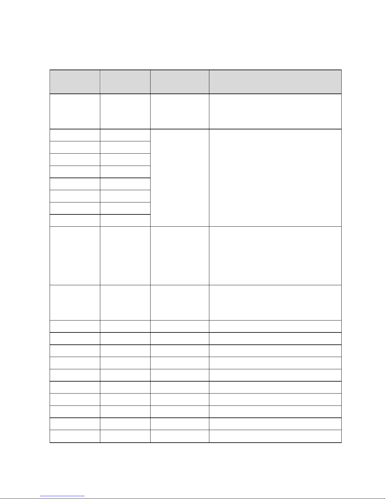
Parallel Pin Assignment
Pin
Signal
Signal
Source
Description
1
/STB
HOST
The HOST (computer)
presents the data on the
data lines and pulses STB.
2
DATA0
HOST
Indicates Data Bit 0 ~ Data
Bit 7 (8 bits)
3
DATA1
4
DATA2
5
DATA3
6
DATA4
7
DATA5
8
DATA6
9
DATA7
10
nAck
Printer
Acknowledge Signal
(Indicates that the printer
has received the data
successfully and ready to
receive the next data).
11
BUSY
Printer
Printer is busy and cannot
receive data from the
HOST.
12
PE
Printer
Printer Paper is out.
13
Select
Printer
High electric potential.
14, 15
N.C.
---
---
16, 17
GND
---
Ground
18
Logic-H
Printer
High electric potential.
19 ~ 30
GND
---
Ground
31
N.C.
---
---
32
nFault
Printer
Printer Error Signal
33
GND
---
Ground
34 ~ 36
N.C.
---
---
Page 38
- 34 -
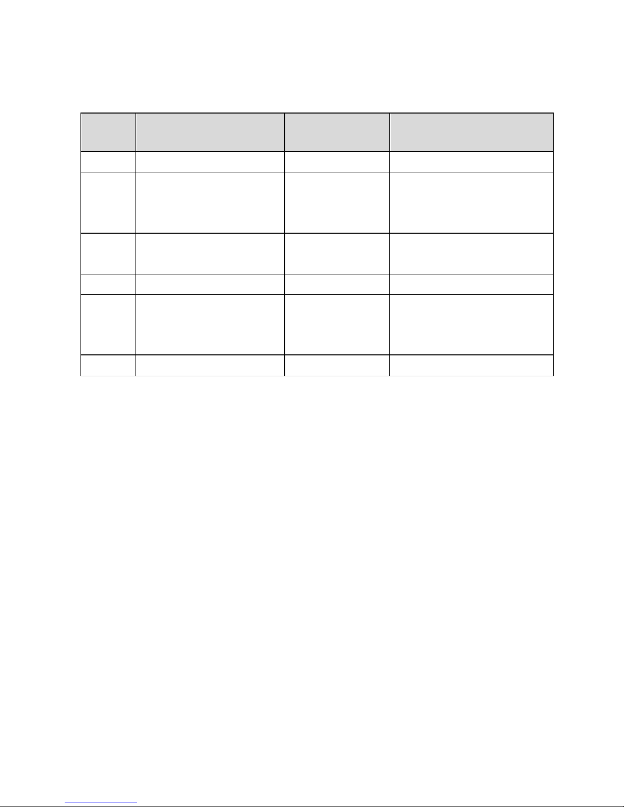
RJ-11 Pin Assignment
Pin
Signal
Signal
Direction
Description
1
Ground
---
Frame Ground
2
Cash Drawer
Kick Out Signal
1
Output
--- 3 Cash Drawer
Status
Input
Open/Close
4
+VDC 24v
---
---
5
Cash Drawer
Kick Out Signal
2
Output
---
6
GND
---
Signal Ground
Page 39
- 35 -
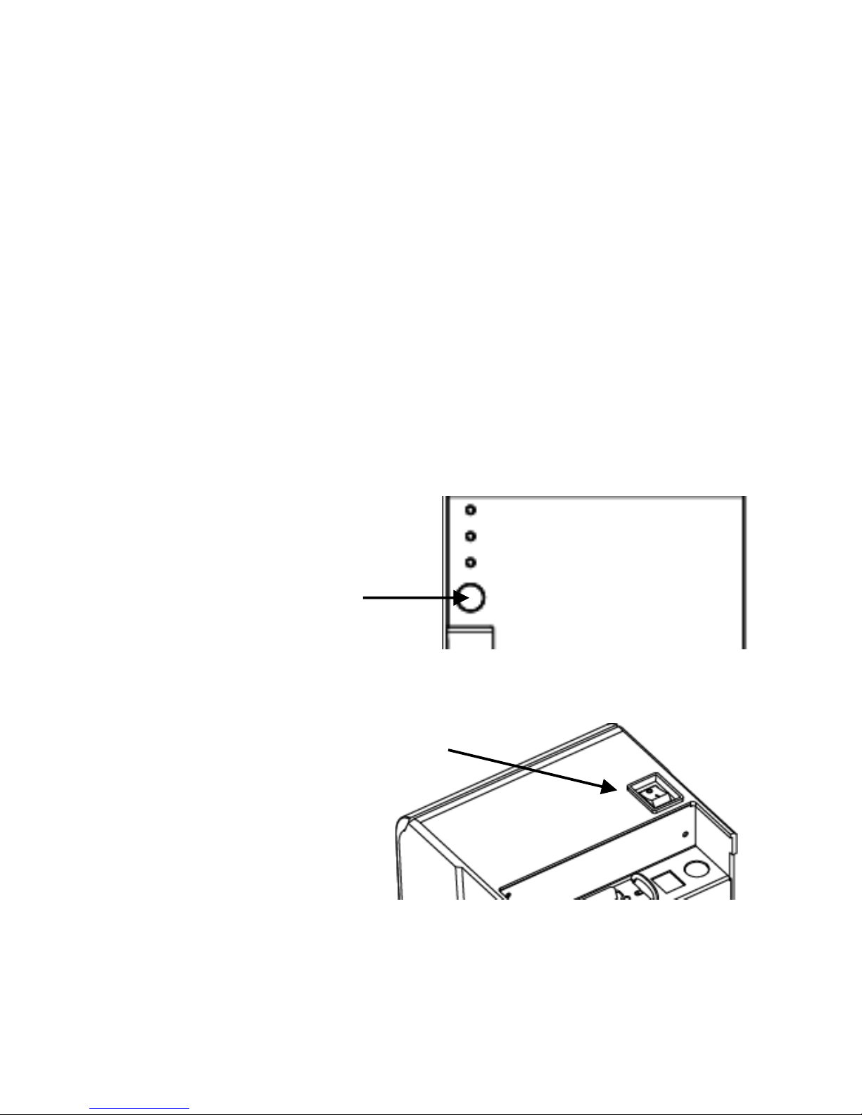
3. Self Test
This function allows user to perform self-test and
print out the settings of the printer unit:
1. Turn off the printer.
2. Press and hold the Paper Feed Button.
3. Turn on the Power Switch of the printer.
4. Release the Paper Feed Button.
The Indicators would blink and then
the printer starts printing out the se-f test data.
Press and hold
the Paper Feed
Button
Turn On the
Power Switch
Paper Feed Button
Power Switch
Page 40
- 36 -
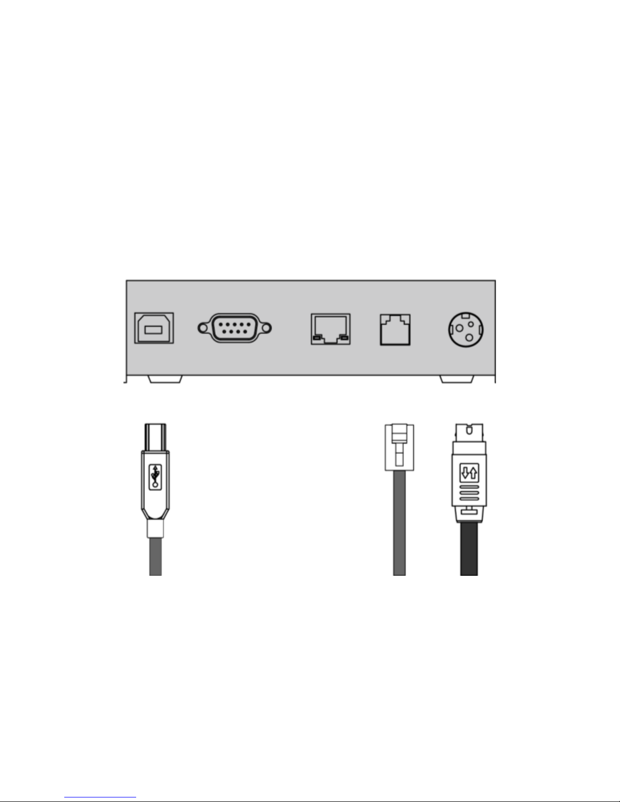
4. Virtual Serial Port Installation
(for USB Connection Only)
When connect the receipt printer to the computer with
USB cable, turn on the computer and the system will found a
new hardware automatically and then initiate the Found New
Hardware Wizard automatically (as image below illustrated):
Printer Cable
(USB)
Cash
Drawer
Power
Adaptor
USB RS-232 RJ-45 RJ-11 PWR
Page 41
- 37 -
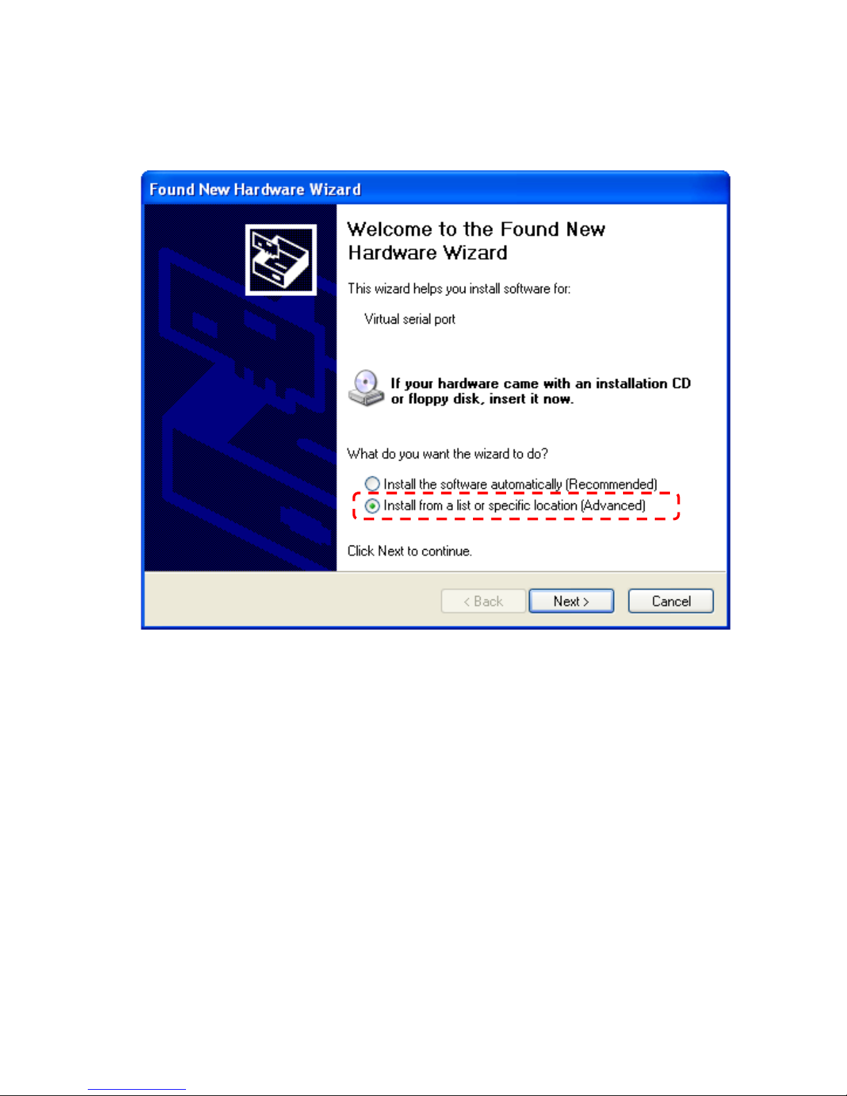
1. Found New Hardware Wizard is initiated; click “Install
from a specific location (Advanced) and then click
“Next” to continue.
Page 42
- 38 -
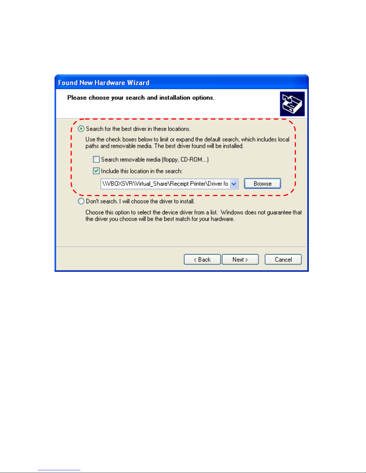
2. To specify the location of driver, click “include this
location in the search and “Browse” the specified
folder manually.
Page 43
- 39 -
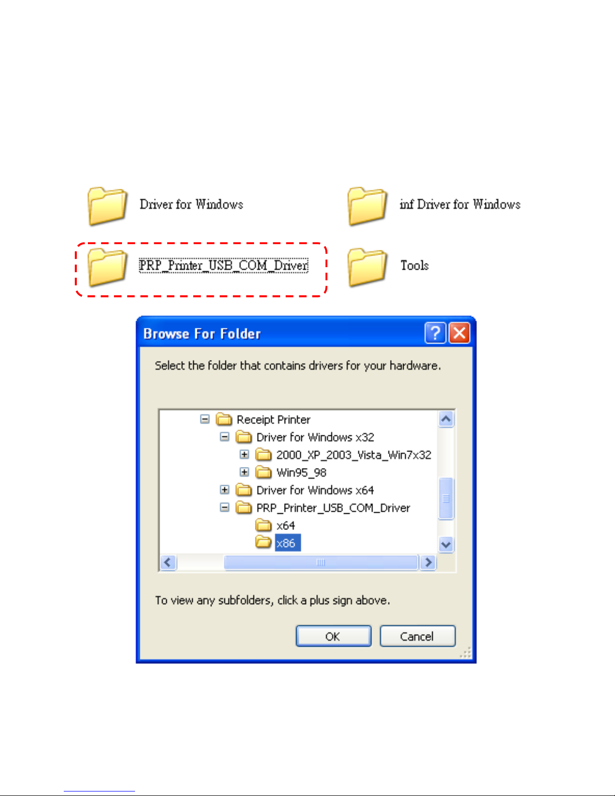
3. Browse the subfolder of the path:” \\Receipt
Printer\PRP_Printer_USB_COM_Driver”
(x86 for Windows XP 32 bit version).
Click “OK” to continue.
Page 44
- 40 -
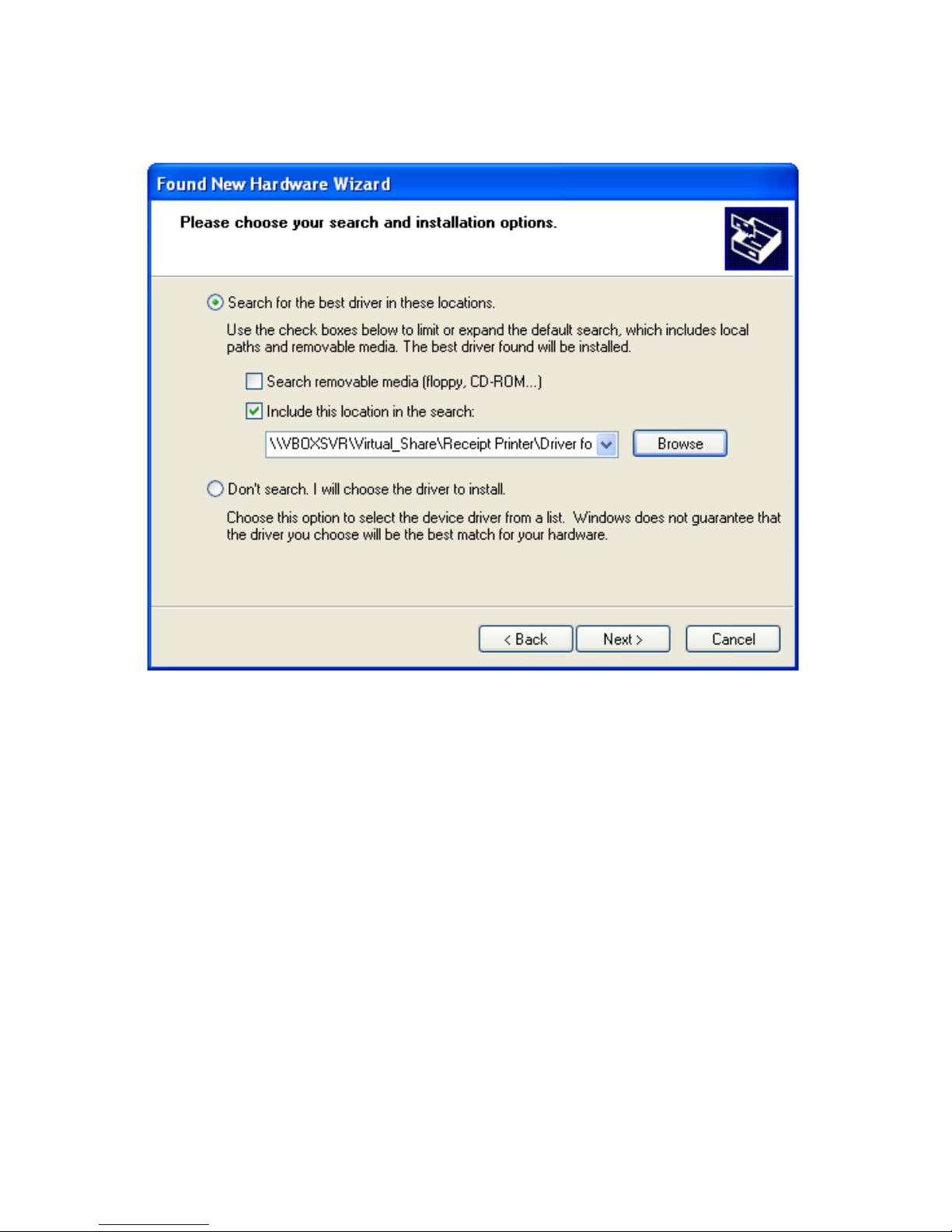
4. As the location of the driver is specified.
Click “Next” to continue.
Page 45
- 41 -
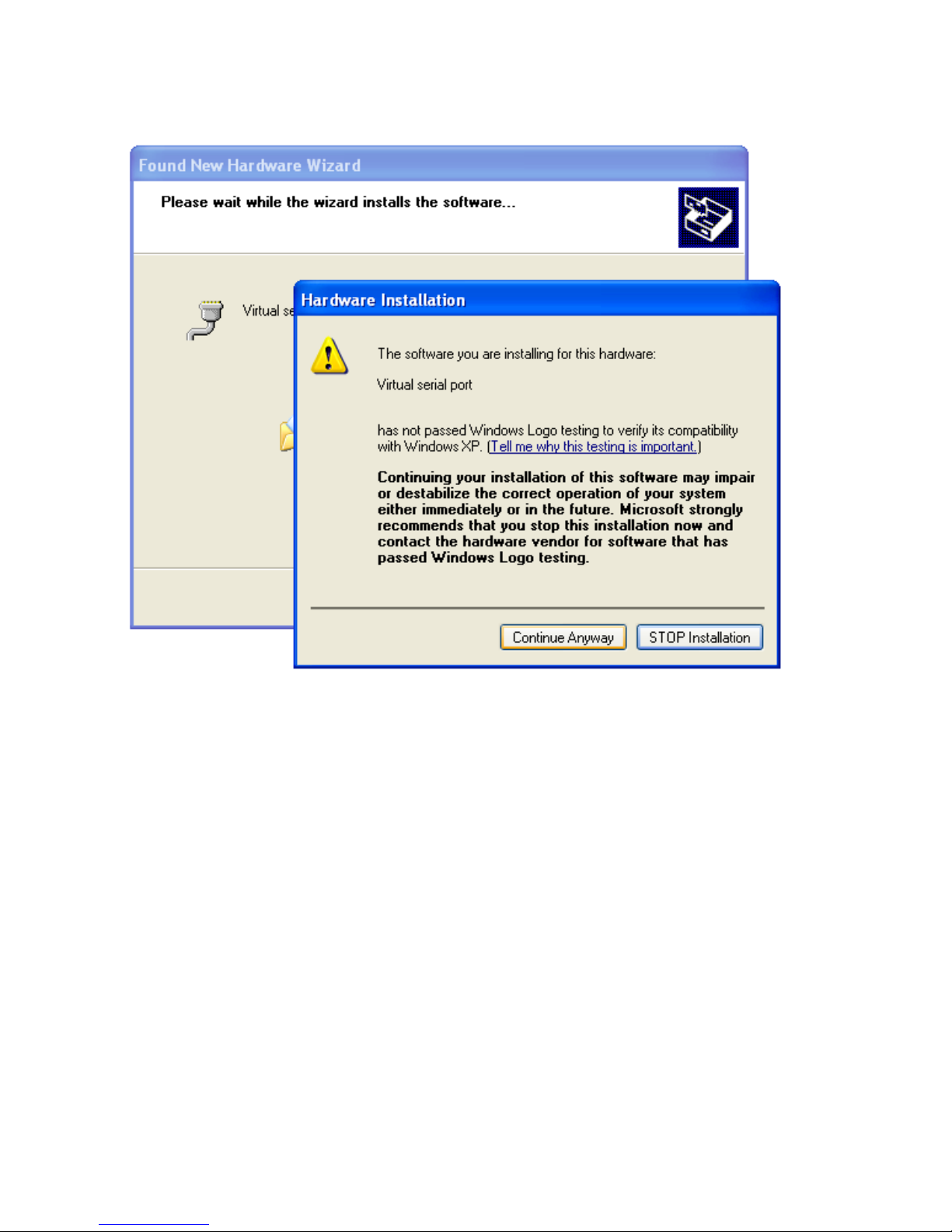
5. Start Notification. Click “Continue Anyway” to continue.
Page 46
- 42 -
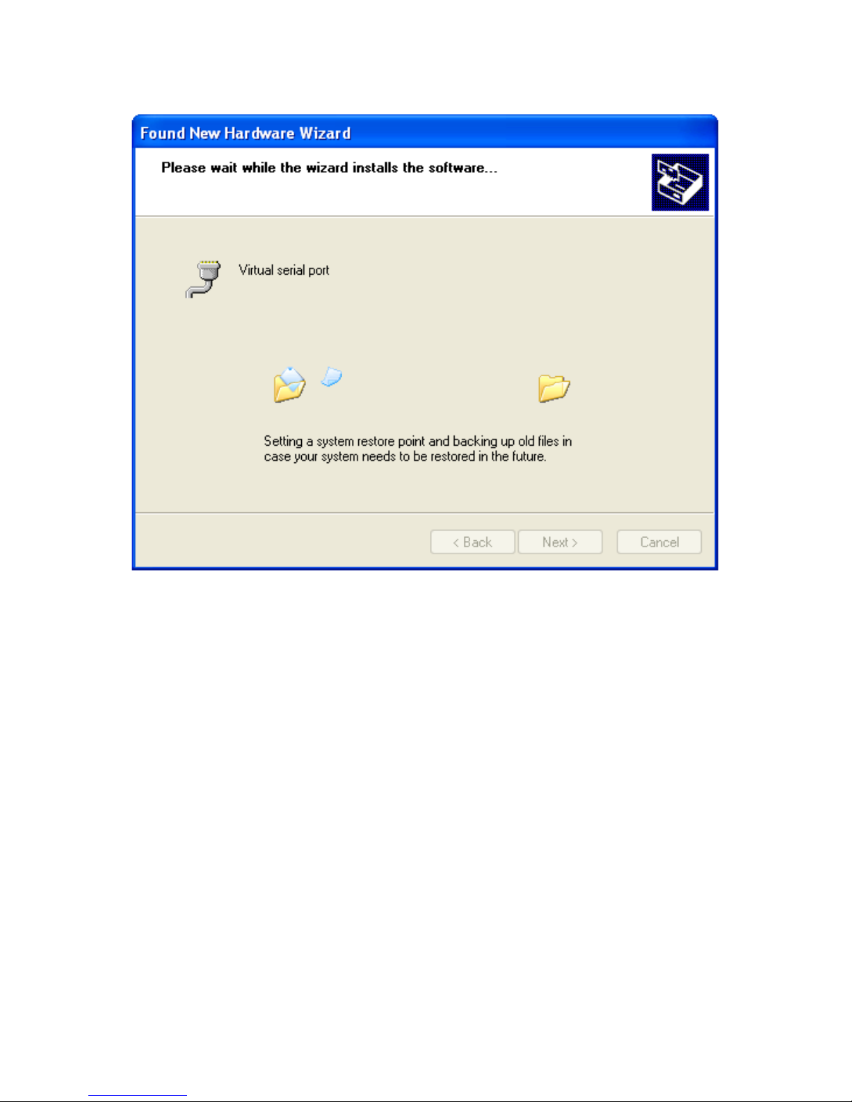
6. The wizard is installing the driver.
Page 47
- 43 -
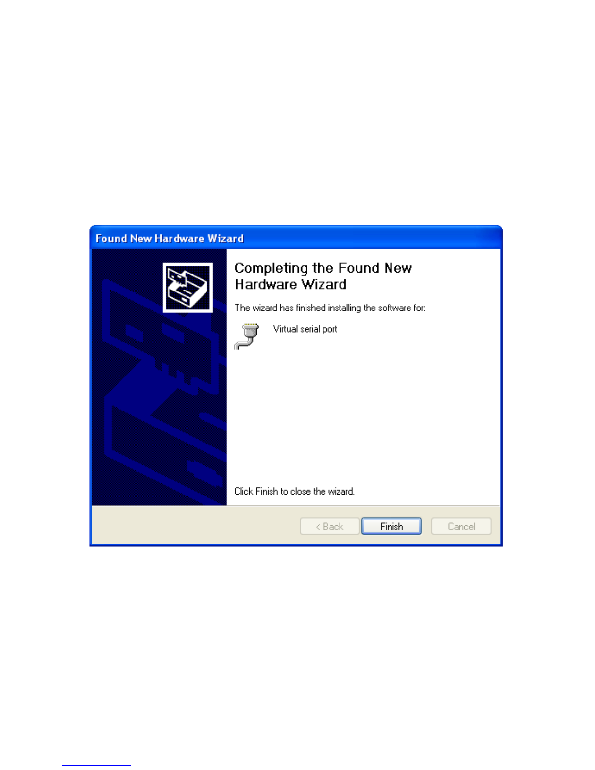
7. The driver of Virtual Serial Port is successfully installed.
Click “Finish” to exit.
Note: Reboot the HOST PC
It’s recommended to reboot the HOST PC and
proceed to the next step.
Page 48
- 44 -
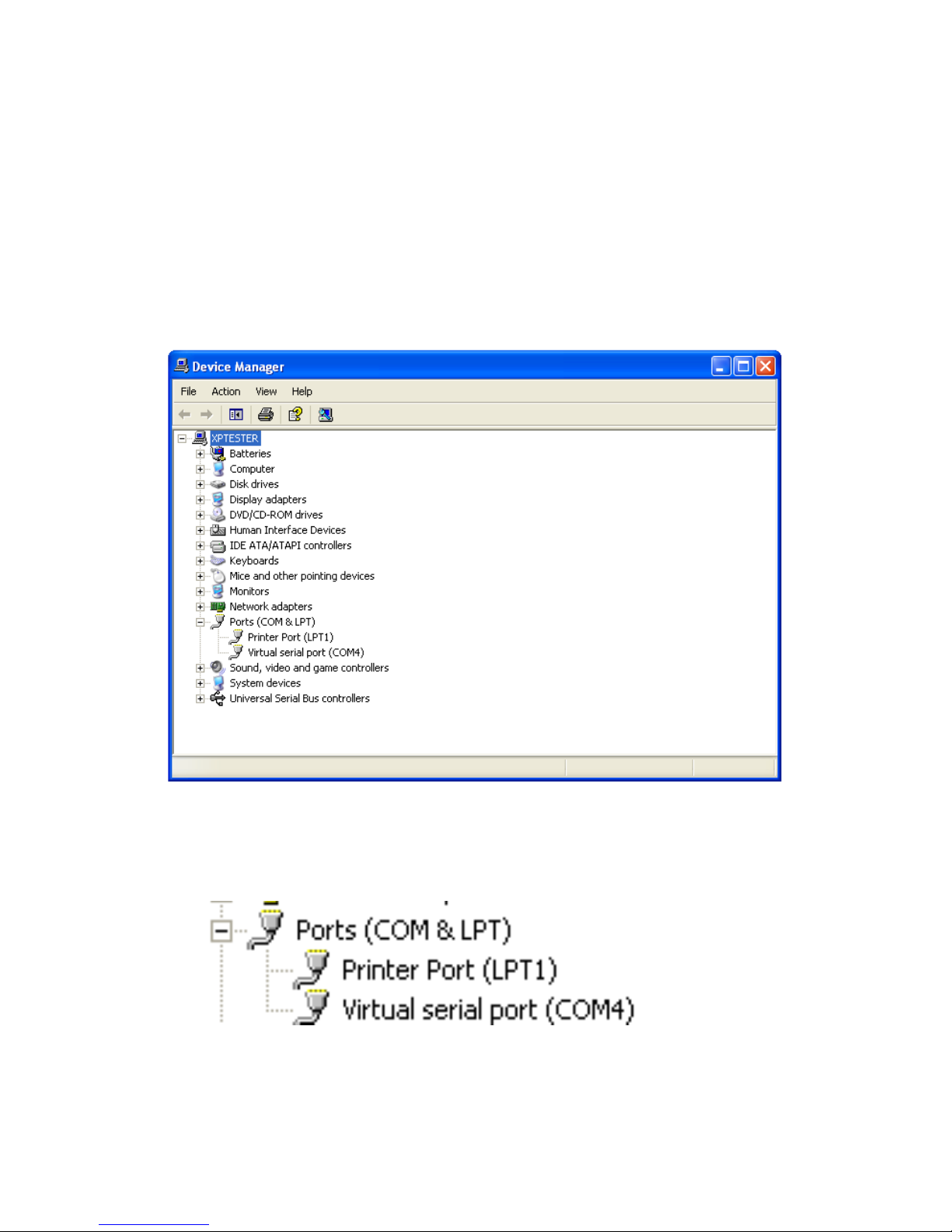
8. The Virtual COM port activates automatically when the
printer is switched on.
You can Access
“My Computer>>Proprieties>>Hardware>>Device
Manager>> Ports (COM & LPT)” and see the
Virtual COM Port Number.
When turn on the printer, the Virtual COM activates
automatically (Virtual Serial Port).
Page 49
- 45 -
5. Ethernet Connection and Configuration
When connecting the printer to the Host PC, you can:
1. Direct Cable Connection:
Use the supplied Ethernet crossover cable to create a
direct cable connection to your Host PC.
Note:
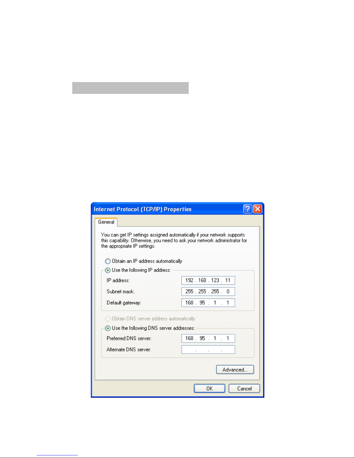
Be sure to assign the IP address of the Host PC under
the same subnet as your Printer
e.g.: Printer: 192.168.123.100
Host: 192.168.123.xxx
Assign the IP address of the Host PC
(Direct Cable Connection)
Page 50

- 46 -
2. DHCP Client Connection:
Connect the printer to the Local Net work (via HUB)
with a standard Ethernet Cable.
The DHCP server will assign an IP address to the
printer.
Be sure to configure the printer to the DHCP Client
Mode before install the printer to the Local Network.
Note:
It’s recommended to consult the MIS personnel relating to
the information about the Local Network and IP address
assignment.
Page 51

- 47 -
Protocols: TCP/IP (A1)
Mac address: X-XXX-XXX-XX
IP address: 192.168.123.100
Netmask: 255.255.255.0
Gateway: 192.168.1.1
DHCP: Disabled
Acquire the IP address of the Printer
You can perform Self-Test of the printer and acquire the IP
address of the printer.
Fixed IP Setting (Default)
If a fixed IP address is assigned to the printer,
perform the self-test and the printer will print out the data.
Print out the Self-test data
Note:
The default IP address is 192.168.123.100
Page 52

- 48 -
Ethernet is configuring…
Mac address: X-XXX-XXX-XX
IP address: 168.95.XXX.XXX
Netmask: 255.255.255.0
Gateway: 192.168.1.1
DHCP: Enabled
DHCP Timeout (s) : 90
DHCP Client Mode
If the printer is set to DHCP Client mode, the DHCP server
will assigned an IP address to the printer when connecting
to the local network.
Perform the self-test and the printer will print out the test
data; then the printer will stand by to receive the IP address
from the DHCP server.
As the IP address is assigned to the printer and
configuration is completed, the printer will print out the
assign IP address.
Note:
The printer will be set to the default IP address
(192.168.123.100) when there is not any IP address
assigned to the printer (DHCP timeout is 90 seconds).
Page 53
- 49 -
IP Reconfiguration
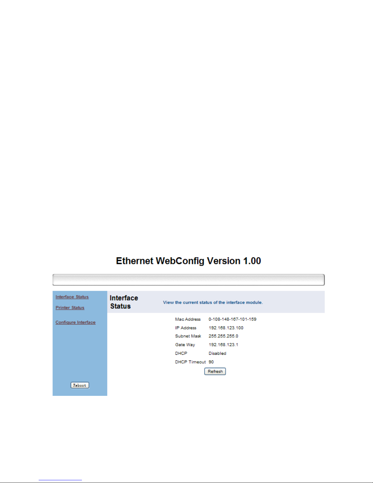
You can open the web-browser and type the IP address to
access the Ethernet WebConfig utility.
Note:
When first re-configuring the IP address of the printer,
you may need to use the supplied Ethernet crossover cable
to establish a direct cable connection to your Host PC and
start IP re-configuration.
Interface Status
This menu displays the current configuration data of the
printer. Click “Refresh” to acquire the newest data.
Page 54
- 50 -
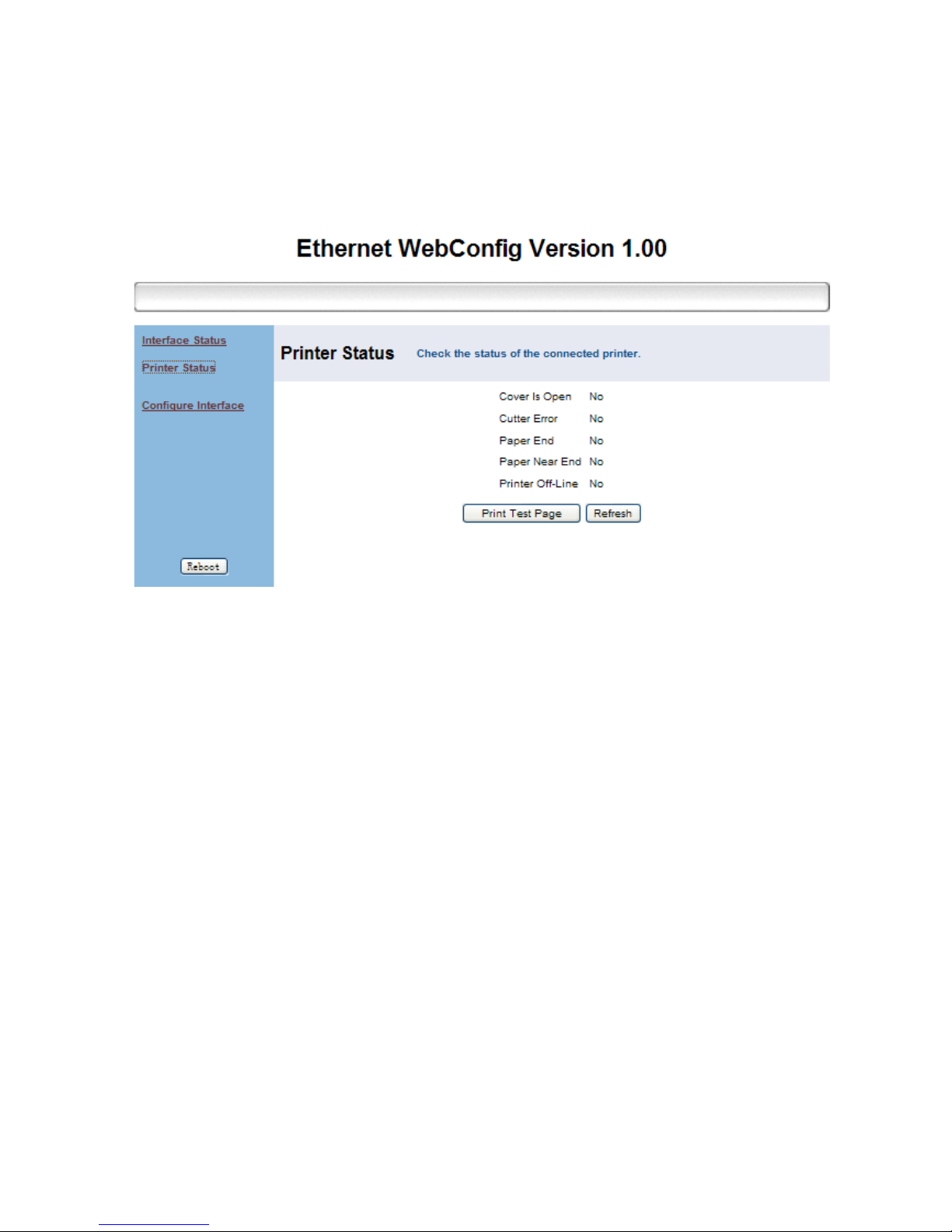
Printer Status
This menu displays the printer status and can perform print
test.
Page 55

- 51 -
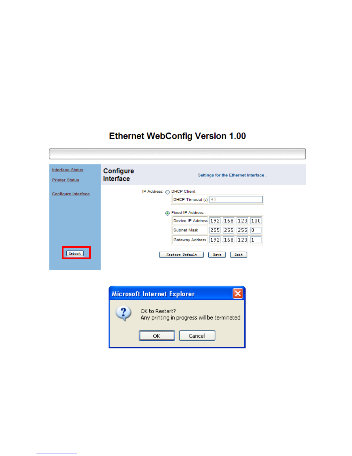
Configure Interface
This menu can change the IP address of the printer.
To change the IP address.
1. Type the new IP address and click “Save” button.
User can set to “DHCP Client” to enable the DHCP
mode.
Note: DHCP Timeout
The DHCP time out is configurable from 14 sec to 90
sec.
2. Click “Reboot” button to re-initiate the printer.
Page 56
- 52 -
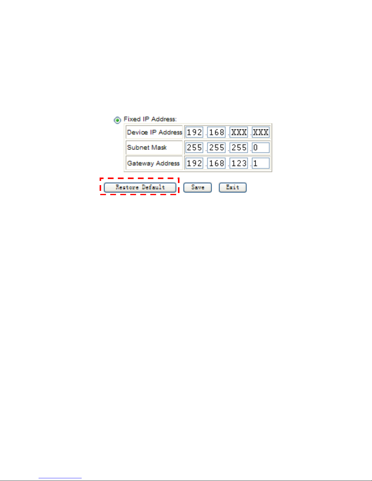
Note: Restore Default Configuration
You can click “Restore Default” button to retrieve the factory
IP configuration data of the printer.
(IP Address: 192.168.123.100)
Page 57
- 53 -
Reboot
This function can re-initiate the printer and apply the new
configuration.
1. Click the “Reboot” button to re-initiate the printer.
Click “OK” to proceed.
Page 58
- 54 -
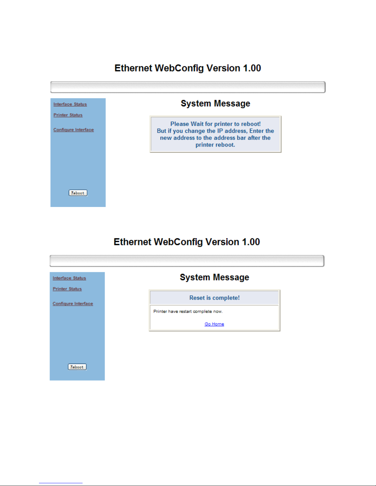
2. The Printer is initiating.
3. Printer is initiated successfully.
Note:
Be sure to access the printer using the new IP address after
reboot the printer.
Page 59
- 55 -
Setup the TCP/IP Printer Port
After the IP address of the printer is re-configured, you can
install the printer driver and setup the printer port of your
printer.
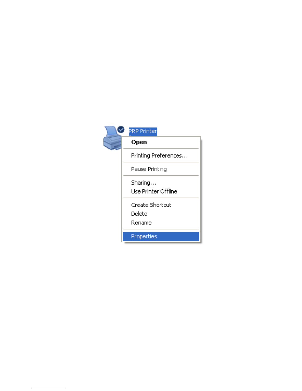
1. Access “Start>>Printer and Faxes>> Printer
properties.
Page 60
- 56 -
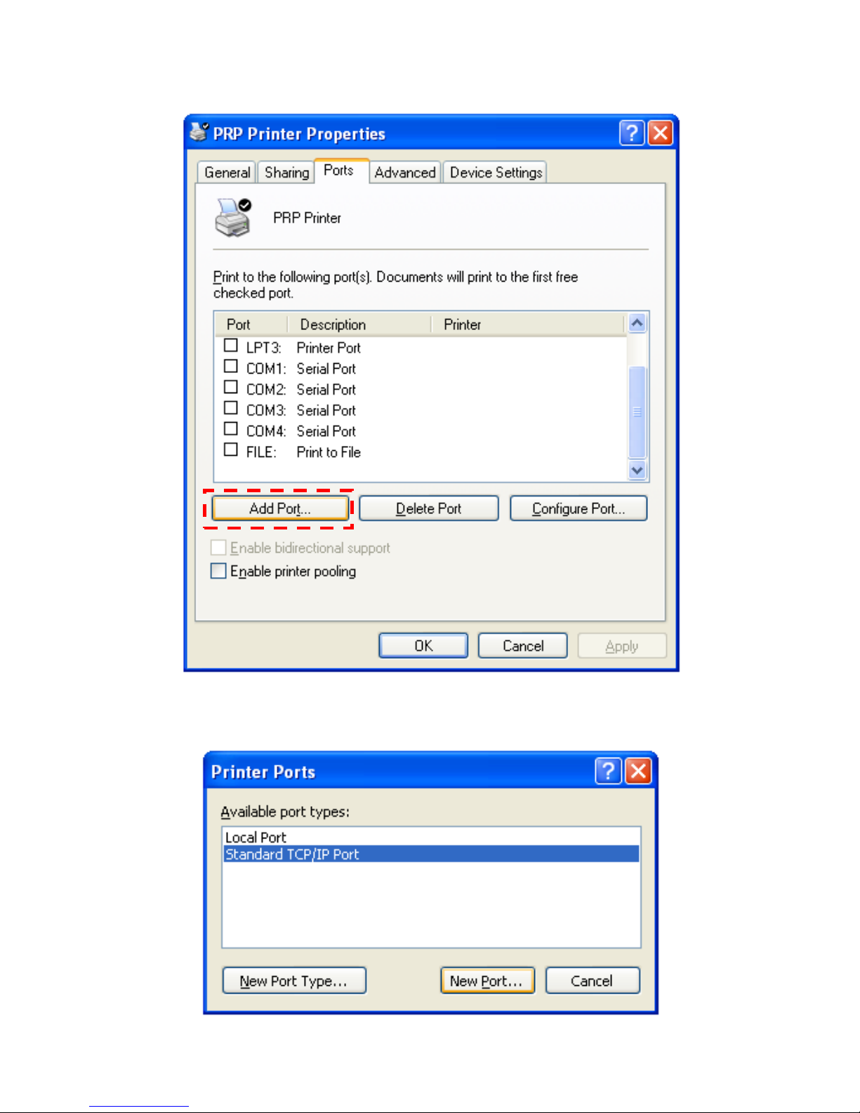
2. Access submenu “Port” and click “Add Port”.
3. Select “Standard TCP/IP Port” and click “New Port.”
and proceed.
Page 61
- 57 -
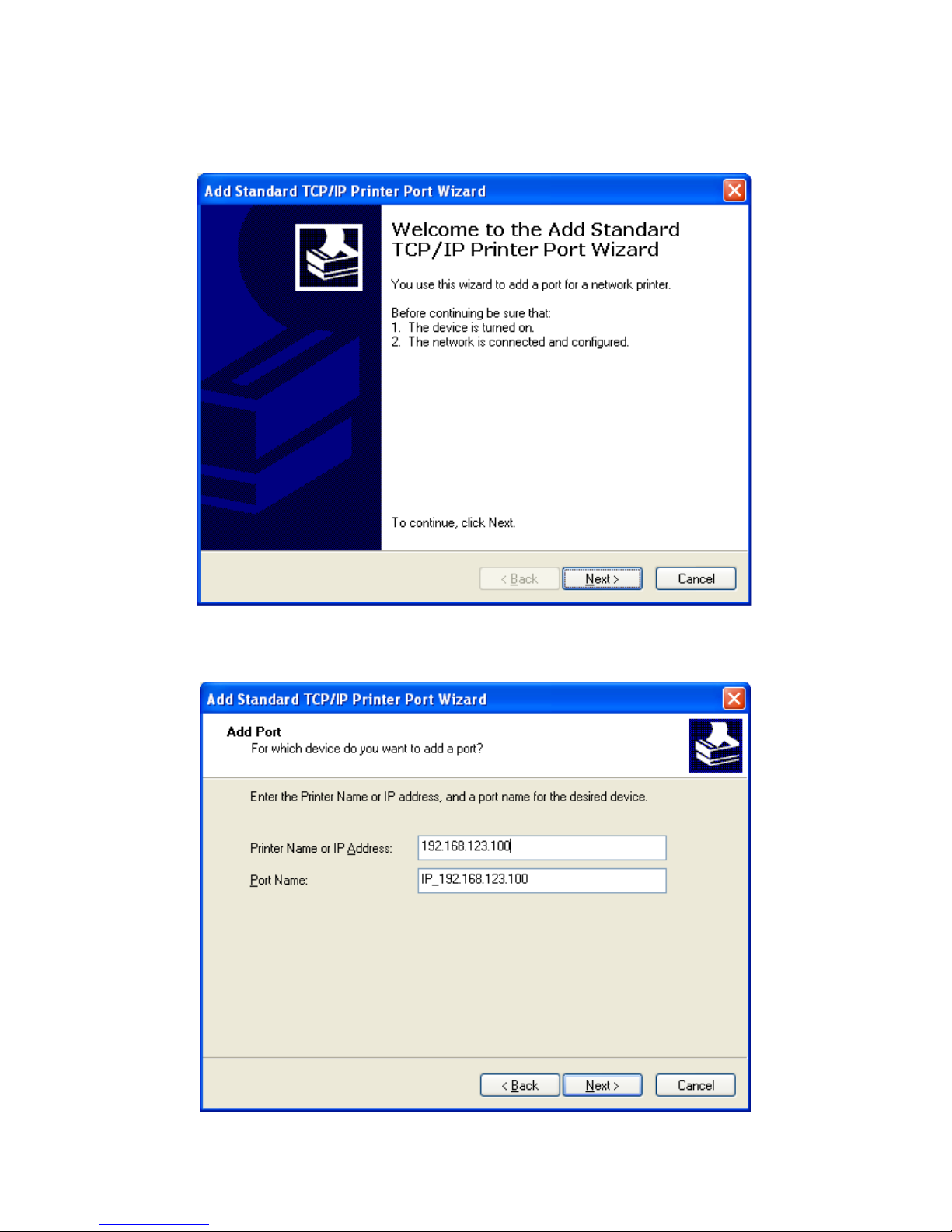
4. Add TCP/IP Print Port Wizard initiated.
Click “Next” to continue.
5. Enter the IP address of the Printer then proceed.
Page 62
- 58 -
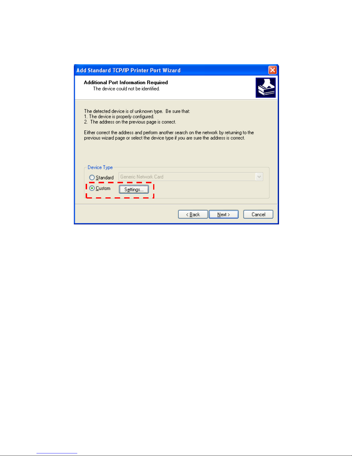
6. Additional Port Information.
Select “Custom” and click “Setting” to continue.
Page 63
- 59 -
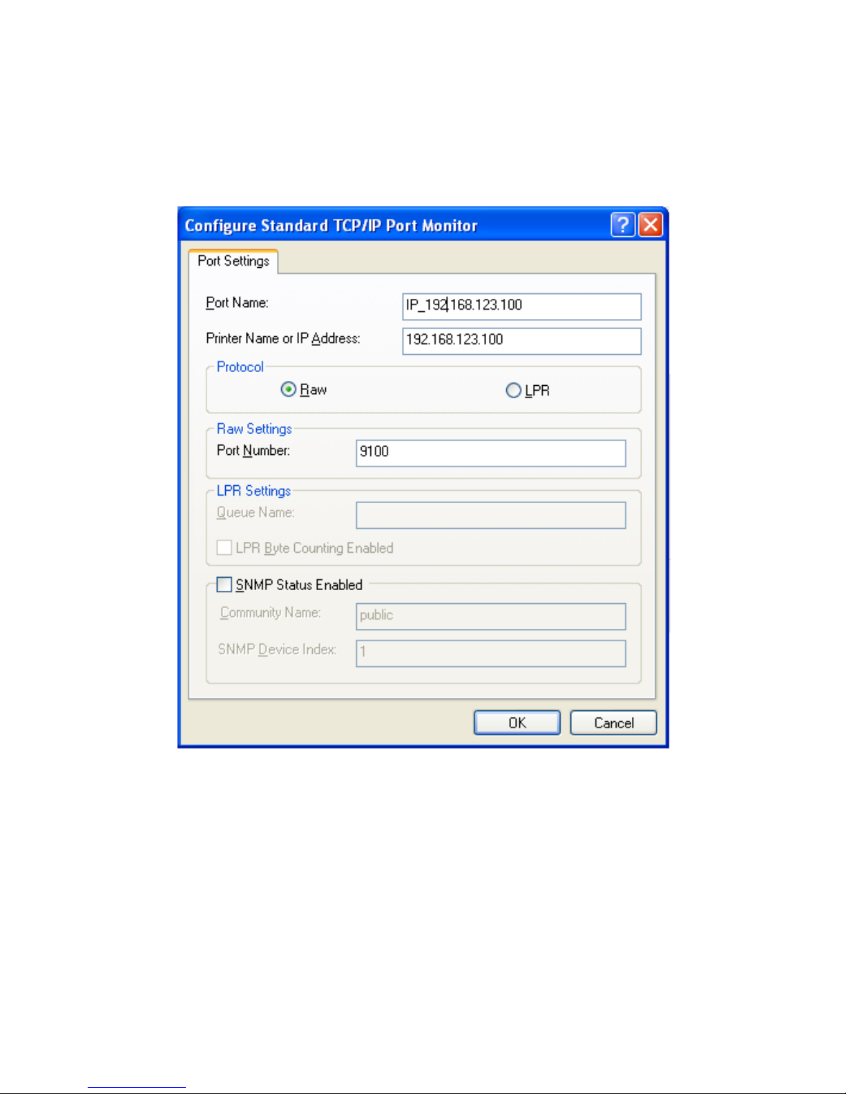
7. Port Setting.
Please examine the IP address should be the same to
the Printer.
Select the protocol “Raw” and click “OK” to continue.
Page 64
- 60 -
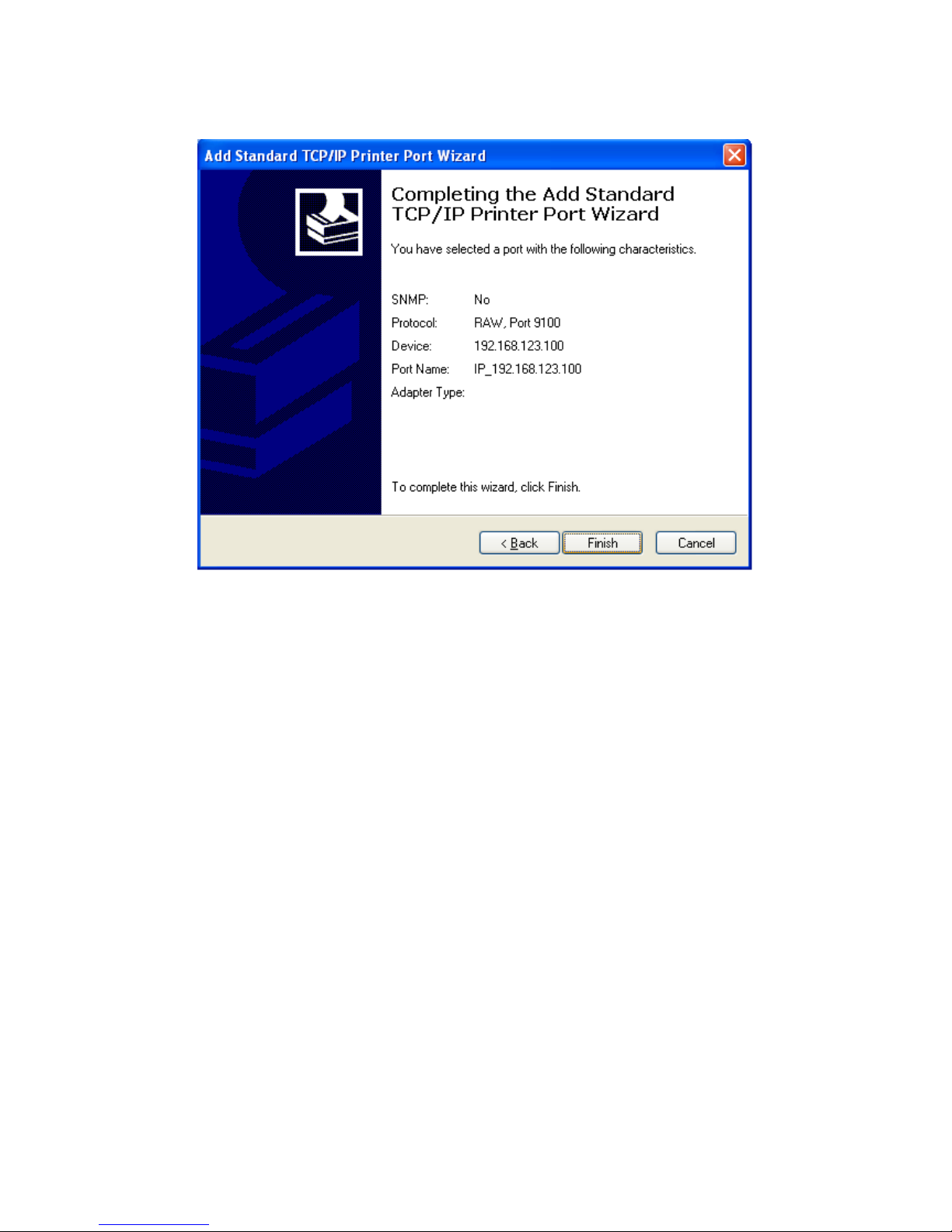
8. Click “Finish” to complete.
Page 65
- 61 -
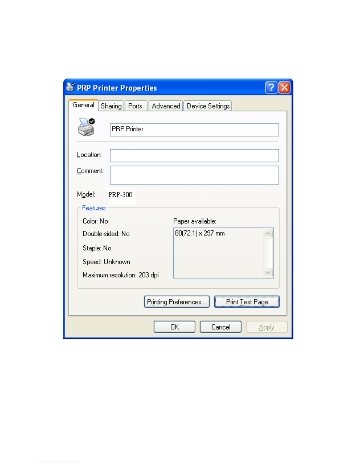
9. You can exit the setting menu and open the printer
properties to perform print test. Click “Print Test Page”
to perform the test.
Page 66
- 62 -
6. Code Page Setup
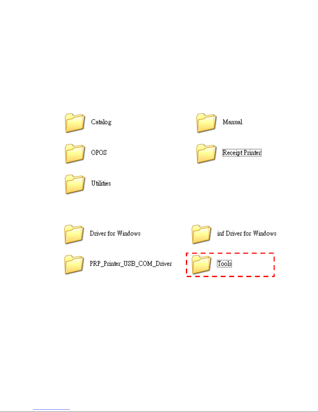
Place the supplied Utility CD into the CD-ROM drive.
1. Browse the CD and open the folder “Receipt Printer” to
install the required software.
2. Open the folder “Tools” to access the utility software.
Page 67
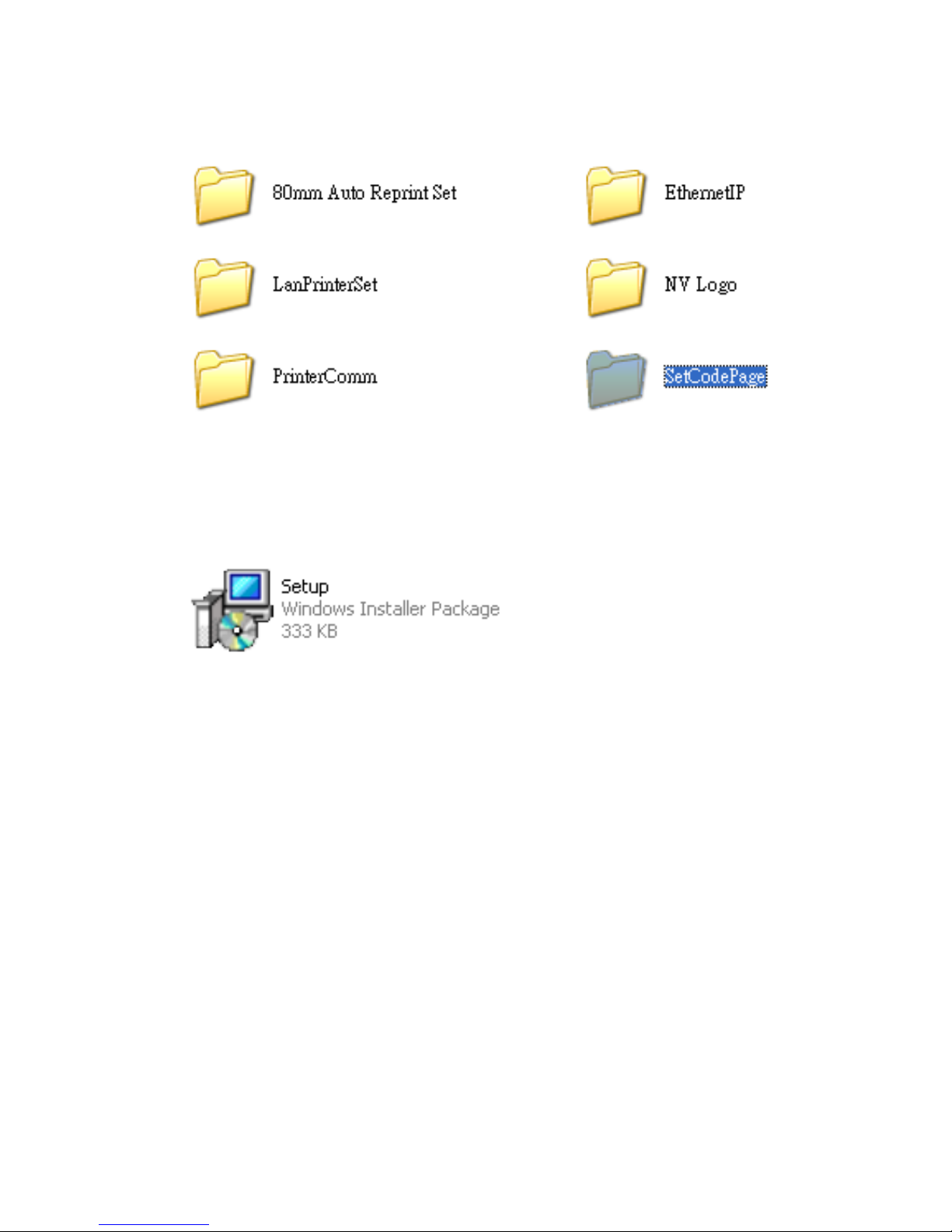
- 63 -
3. Click the folder “SetCodePage” to access the
software
4. Double click the icon “Setup.EXE” to initial installation.
Follow the instructions to install the utility.
Page 68
- 64 -
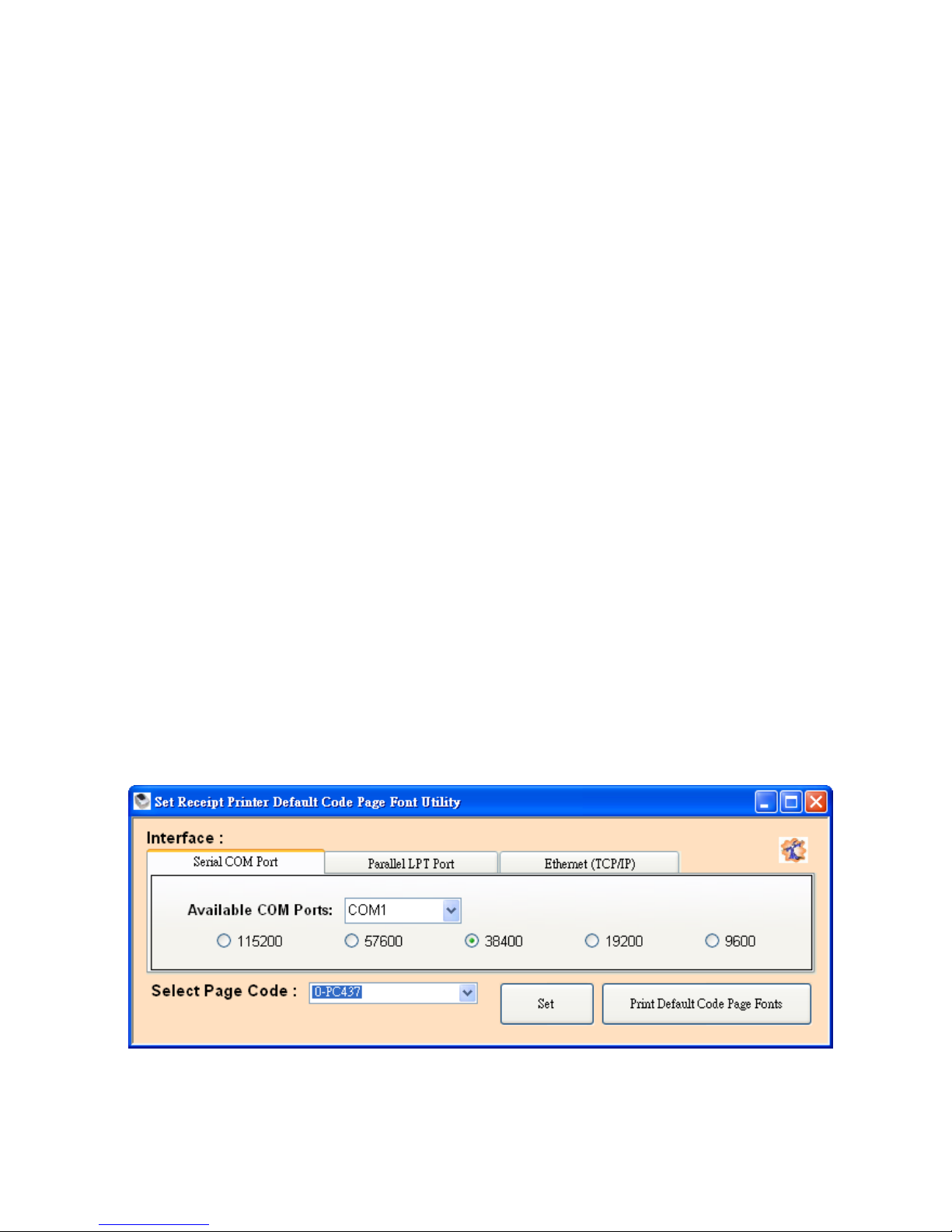
Code Page Setup Utility
This utility can help user to setup the code page of the
printer.
Note: Before Setup
It may need to re-configure the printer prior to the codepage
setup (e.g.: DIP switch).
It’s recommended to consult the technical personnel relating
to the information about the code page and application.
Interface
User can establish communication with printer via this menu.
Select the proper submenu by the connection type of the
printer.
For Serial COM Port:
Select the proper COM port and baud rate to establish
communication.
Page 69
- 65 -
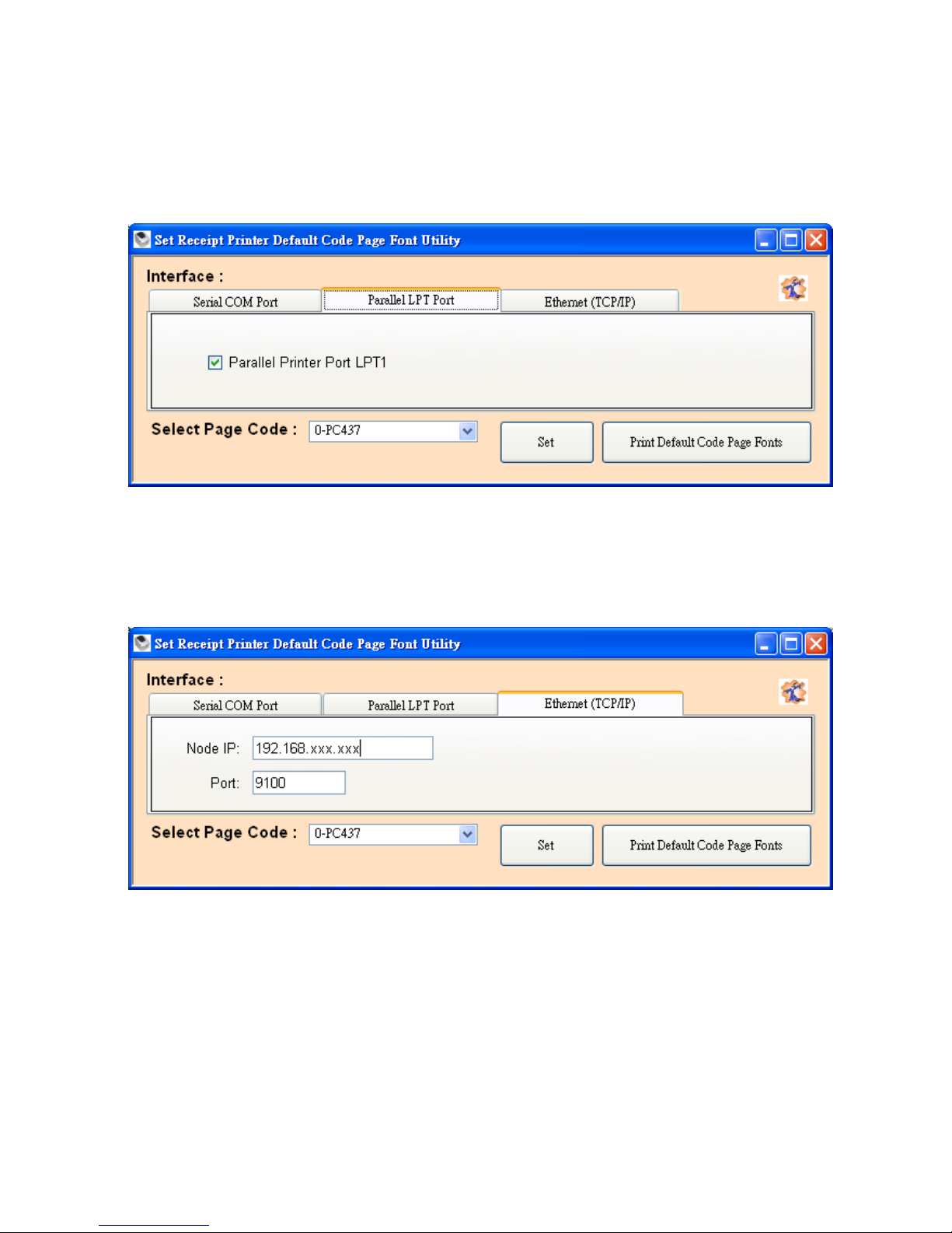
For Parallel LPT Port:
Select LPT1 as the printer port to establish communication.
For Ethernet (TCP/IP):
Enter the IP address of the printer to establish the
communication.
Page 70
- 66 -
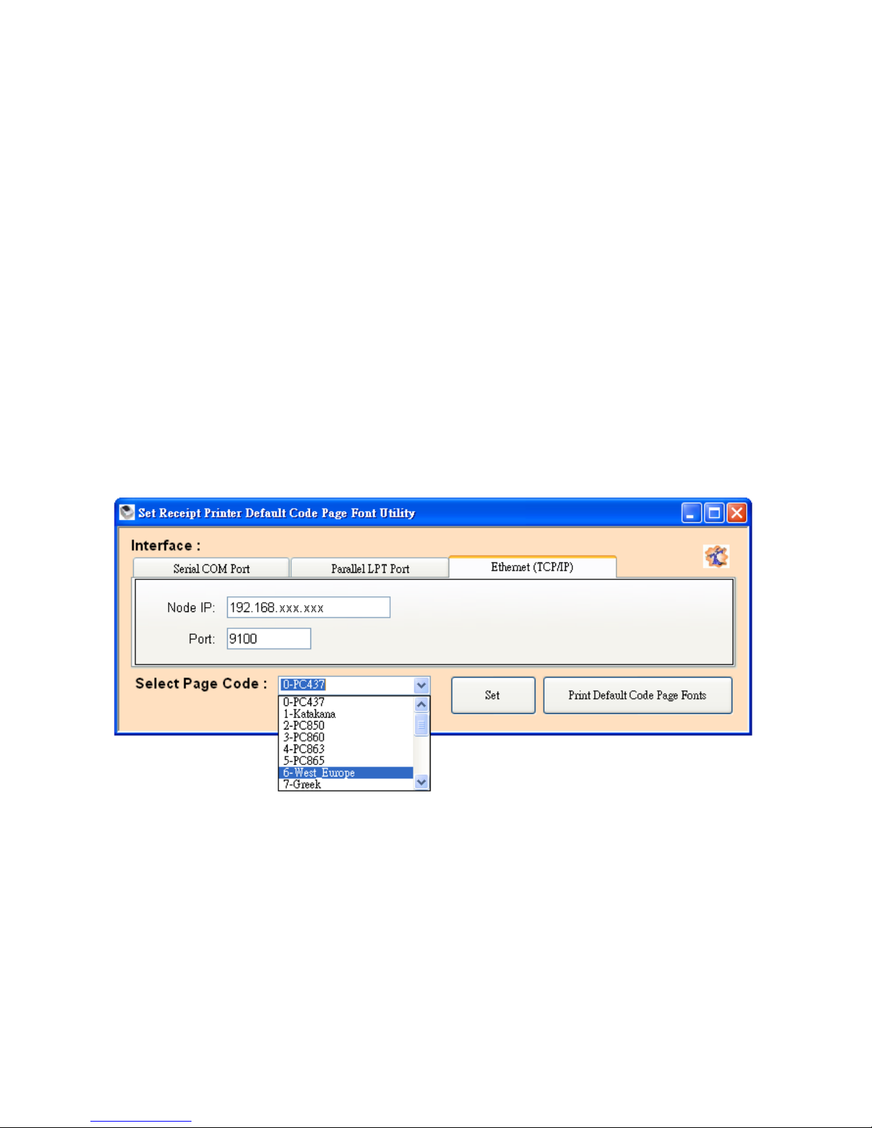
Select Page Code
To select the codepage desired:
1. Make sure to the DIP switch 4 of the printer is set ON
(please refer to DIP Switch Configuration for further
information).
2. Go to the scroll menu and select the preset codepage
desired.
User can enter the codepage number into the field
manually. (Please refer to the printed Self-Test page
for the code number support).
3. Click “Set” button to confirm the setting.
4. Re-initiate the Printer:
Be sure to Turn-Off and Turn-On the printer again to
initiate the printer with new codepage setting.
(User can perform the self-test again to exam the new
codepage setting)
Page 71

- 67 -
Page 72

20121110
 Loading...