

Page 1
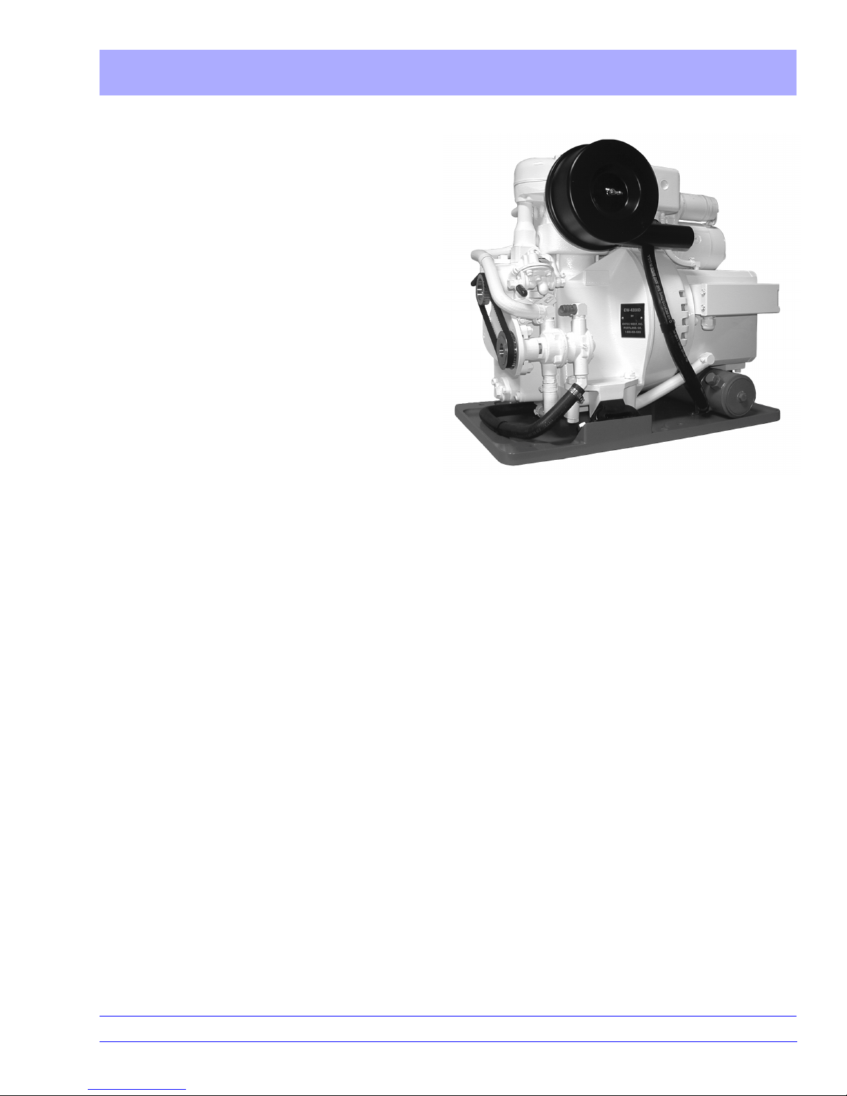
Operating Instructions EW-4200D
ENTEC WEST, INC.
Marine Diesel
Generators
Table of Contents
How to Use this Manual . . . . . . . . . . . . . . . . . . . . . . . . . . . . . . . . . . . . . . . . . . . . . . . . 2
System Descriptions
Fuel System . . . . . . . . . . . . . . . . . . . . . . . . . . . . . . . . . . . . . . . . . . . . . . . . . . . . . . . . . . 3
Water Pumps . . . . . . . . . . . . . . . . . . . . . . . . . . . . . . . . . . . . . . . . . . . . . . . . . . . . . . . . . . 3
Fresh Water Cooling System . . . . . . . . . . . . . . . . . . . . . . . . . . . . . . . . . . . . . . . . . . . . . 4 & 5
Raw Water Cooling System . . . . . . . . . . . . . . . . . . . . . . . . . . . . . . . . . . . . . . . . . . . . . . 6
Lubrication . . . . . . . . . . . . . . . . . . . . . . . . . . . . . . . . . . . . . . . . . . . . . . . . . . . . . . . . . . . 7
Engine Control System . . . . . . . . . . . . . . . . . . . . . . . . . . . . . . . . . . . . . . . . . . . . . . . . . . 7 – 9
Safety Stops . . . . . . . . . . . . . . . . . . . . . . . . . . . . . . . . . . . . . . . . . . . . . . . . . . . . . . . . . . 9
Operation
Starting the Engine for the First Time . . . . . . . . . . . . . . . . . . . . . . . . . . . . . . . . . . . . . . 10 & 11
Normal Engine Starting . . . . . . . . . . . . . . . . . . . . . . . . . . . . . . . . . . . . . . . . . . . . . . . . . 12
Generating A.C. Power. . . . . . . . . . . . . . . . . . . . . . . . . . . . . . . . . . . . . . . . . . . . . . . . . . 13
Emergency Stop . . . . . . . . . . . . . . . . . . . . . . . . . . . . . . . . . . . . . . . . . . . . . . . . . . . . . . . 13
Manual Hand Starting. . . . . . . . . . . . . . . . . . . . . . . . . . . . . . . . . . . . . . . . . . . . . . . . . . . 14
Periodic Maintenance
Changing the Oil. . . . . . . . . . . . . . . . . . . . . . . . . . . . . . . . . . . . . . . . . . . . . . . . . . . . . . . 15
Air Cleaner . . . . . . . . . . . . . . . . . . . . . . . . . . . . . . . . . . . . . . . . . . . . . . . . . . . . . . . . . . . 15
Valve Adjustment . . . . . . . . . . . . . . . . . . . . . . . . . . . . . . . . . . . . . . . . . . . . . . . . . . . . . . 16
Heat Exchanger. . . . . . . . . . . . . . . . . . . . . . . . . . . . . . . . . . . . . . . . . . . . . . . . . . . . . . . . 16
Raw Water Pump Maintenance . . . . . . . . . . . . . . . . . . . . . . . . . . . . . . . . . . . . . . . . . . . 17
Theory of Operation–How Compression Ignition Works . . . . . . . . . . . . . . . . . . . . . 18 & 19
16710 SW 72nd • Portland, Oregon 97224 • (503) 624-7118
Page 2
How to Use this Manual EW-4200D
We congratulate you on your purchase of the Model EW-4200D generator. These operating instructions
are based on the most recent state of development, and every possibile effort has been taken to exclude
errors and omissions.
All those involved in the installation and operation of this unit should read the Installation Instructions
and the Operating Instructions carefully, before installing and operating the generator. If any questions
remain after reading these documents, we suggest you call the factory for further assistance.
1-800-458-5065
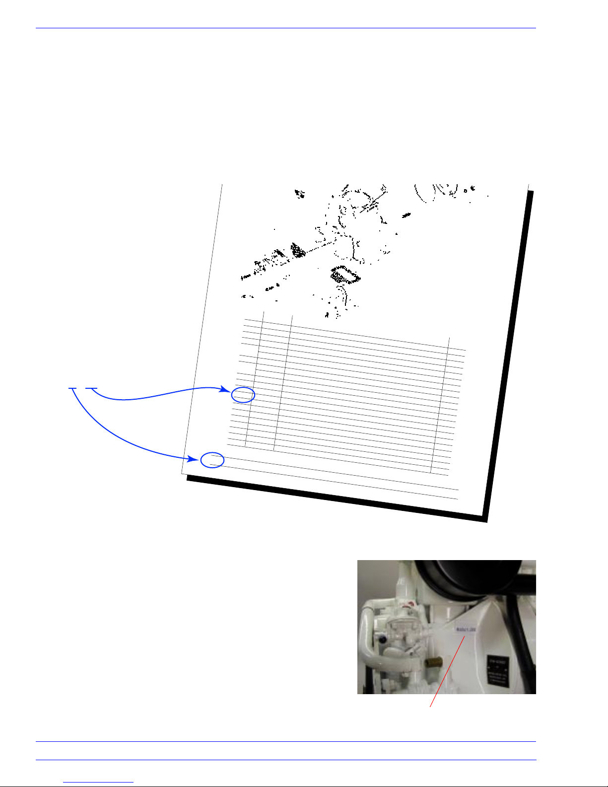
References in parenthesis, as
noted in these instructions, refer
to the Spare Parts List. The first
number indicates the Page
number; the second number is
the Item or Reference number,
ie: (2/12), means Page 2 Item 12.
REF PART NO.
(2/12)
1 711-1187
2 512-0884
3 512-0894
4 512-0904
237-0032
5
237-40-07
7
770-1484 Oil Cooler Gasket
124-10-48 Oil Cooler, EW-4200-D (S/N 62947/01 and Later)
8
124-10-47
9
890-3106
10 850-0214
11 727-0514
12 890-2023
13 890-5957
14 890-3805
15 890-6603
16 724-0206
17 770-1674
18
890-7802
19 890-3106
20 890-3131
●
Included in Complete Gasket Set 770-2618
2
Crankcase (includes Items 2, 3, and 4)
Rear Cylinder Stud
Front Cylinder Stud
Stud, Main Bearing Plate
Low Oil Pressure Switch, 12/18 PSI (C Series) (Normally Closed)
Low Oil Pressure Switch, 15 PSI (D Series) (Normally Open)
Oil Cooler, EW-4200-C (S/N 61831/20 and Before)
Socket Head Capscrew, M06 x 20 (Torque 7 ft.-lbs.)
O-Ring, 99mm x 3.0mm
Main Bearing Plate
Internal Snap Ring, 80mm x 2.5mm
Seal, 60mm x 80mm x 08mm, Type BA
Nut, M08 (Torque 22 ft.-lbs.)
Internal Tooth Lockwasher, M08
Oil Pump
Oil Pump Gasket
Split Spring Lockwasher, M06
Socket Head Capscrew, M06 x 20 (Torque 7 ft.-lbs.)
Socket Head Capscrew, M06 x 30 (Torque 7 ft.-lbs)
16710 SW 72nd
• Portland, Oregon 97224
Crankcase
DESCRIPTION
•
(503) 624-7118
Serial Number
Entec W
1 ●
1
1
6
1
1
1
1
4
4
1
1
●
3
1
2
est, Inc.
1
QTY
4
1
●
1
2
2
The engine/generator has been thoroughly tested at the factory.
All pertinent data including, but not limited to, oil pressure,
output voltage, output current, and frequency, have been
recorded in our permanent file system. All technical and/or
service questions will be answered correctly, when the engine
Serial Number is provided (2/0). When contacting us for assistance, please provide the Serial Number of your unit.
2
16710 SW 72nd • Portland, Oregon 97224 • (503) 624-7118
Serial Number
Entec West, Inc.
Page 3
System Descriptions EW-4200D
FUEL SYSTEM
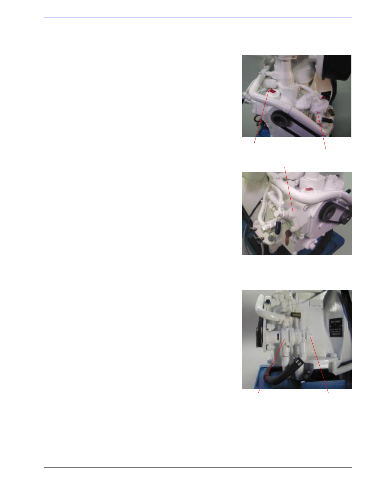
In a normal installation, fuel is drawn out of the fuel tank
through the primary “water/separator fuel filter” by the engine
driven, diaphram type, Fuel Pump (3/50). From the Fuel Pump it
goes first through the engine Fuel Filter (11/10), then to the Fuel
Injection Pump (3/29).
It is important to know that most of the fuel delivered to the Fuel
Injection Pump by the Fuel Pump, is surplus, and is returned to
the fuel tank. The Fuel Pump is pumping at a rate of approximately 3.17 gallons per hour. The Fuel Injection Pump will only
use 0.4 of a gallon per hour (when the generator is producing 30
amps of electrical power). The high volume of return flow
provides a continuous cleaning action of the fuel through the
vessel’s filter. This will help to keep the fuel in the tank clean.
Fuel Filter
Fuel Pump
Fuel Injection Pump
WATER PUMPS
The Water Pumps are flexible impeller types. Each pump is
complete and independent of the other, except the Raw Water
Pump is “piggybacked” onto the Fresh Water Pump. The shaft
tang of the Raw Water Pump extends beyond the pump housing
and fits into the pump shaft slot of the Fresh Water Pump (21/0).
Fresh Water
Pump
Raw Water
Pump
Entec West, Inc.
16710 SW 72nd • Portland, Oregon 97224 • (503) 624-7118
3
Page 4
System Descriptions EW-4200D
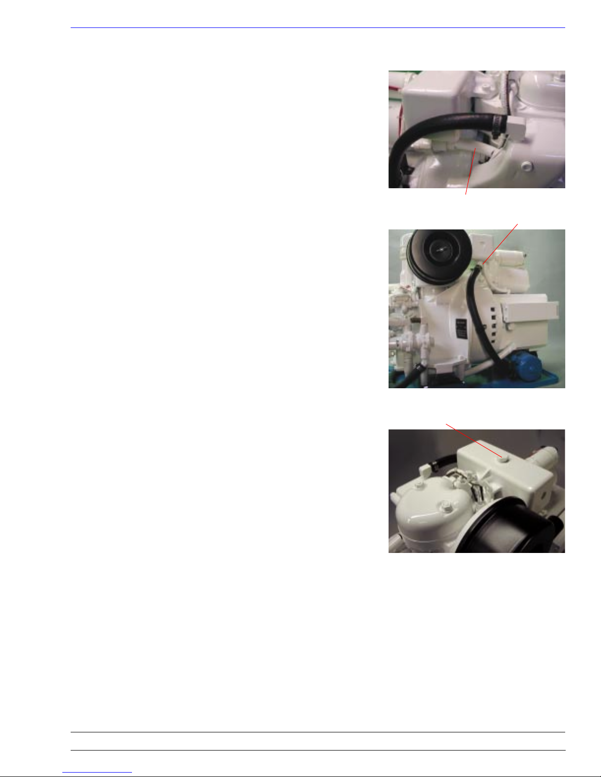
FRESH WATER COOLING SYSTEM
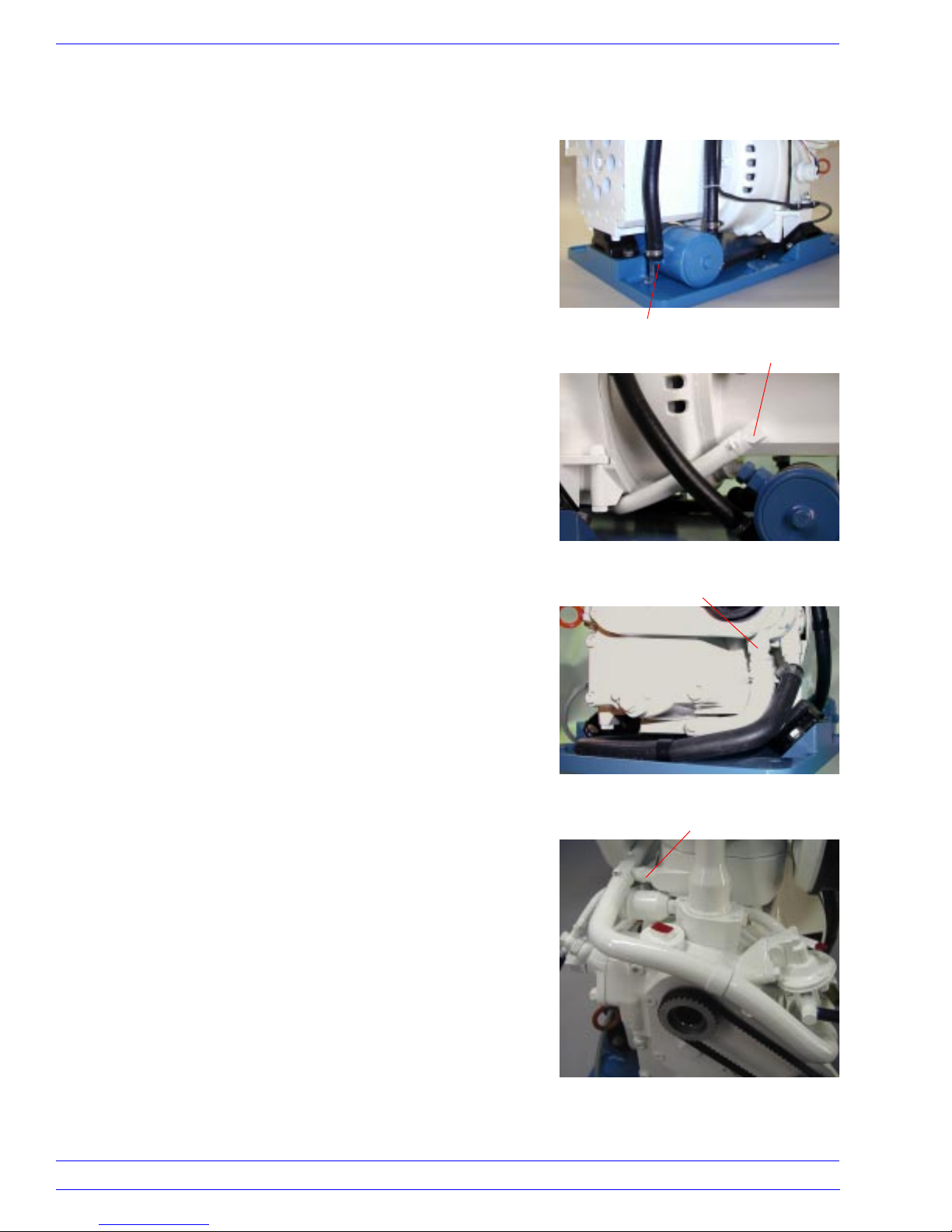
The cooling system is in two parts. The fresh water, closed loop
system, and the raw water, open end system. The closed loop
system uses a combination of fresh water and anti-freeze for the
cooling medium. Beginning at the outlet of the Heat Exchanger
(16/1), the coolant flows through the hose (16/17) into the rear,
upper left corner of the Generator Housing (14/15).
Heat Exchanger Outlet
Generator Outlet
After circulating through the Generator Housing, it flows from
the lower front, right side of the Generator Housing,
through the Oil Cooler (2/8) in the base of the engine, to the
input side of the Fresh Water Pump (front pump 15/9).
The pump pushes the coolant across the front of the engine to
the Bypass Tee (15/17) connection on the cylinder. A portion of
the mixture goes into the cylinder cooling passages, up through
the cylinder ports (7/25) and into the cylinder head cooling
chamber.
Input Side – Fresh Water Pump
Bypass Tee
4
16710 SW 72nd • Portland, Oregon 97224 • (503) 624-7118
Entec West, Inc.
Page 5
System Descriptions EW-4200D
FRESH WATER COOLING SYSTEM (cont.)
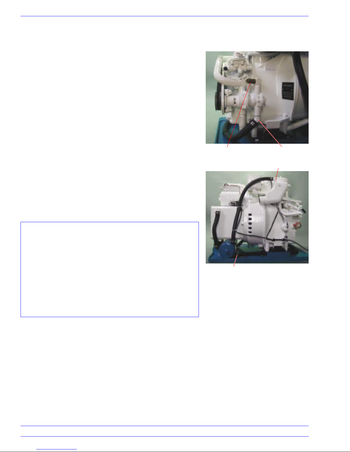
The top of the Cylinder Head has a recess for the Thermostat
(8/53). The coolant flow is held back until the Thermostat starts
to open at approximately 170 degrees F.
As long as the Thermostat is closed, the excess flow will bypass
the Cylinder and Cylinder Head, and go directly to the Reservoir
(8/56) through the Bypass Hose (15/19).
Bypass Hose
Reservoir Outlet
When the Thermostat opens, the Cylinder and Cylinder Head
flow goes through the thermostat and into the Reservoir, where
it joins the bypass flow. From there the warm coolant returns to
the Heat Exchanger (hose 16/16) where the accumulated heat is
transferred to the raw water.
The closed loop cooling system has been charged, at the factory,
with a 50/50 mixture of fresh water and permanent anti-freeze.
The Reservoir (8/54), was specially designed to prevent over
filling. The correct level is to the bottom of the threads. We
recommend checking the level each time the oil is changed.
Reservoir Fill Plug
Entec West, Inc.
16710 SW 72nd • Portland, Oregon 97224 • (503) 624-7118
5
Page 6
System Descriptions EW-4200D
RAW WATER COOLING SYSTEM
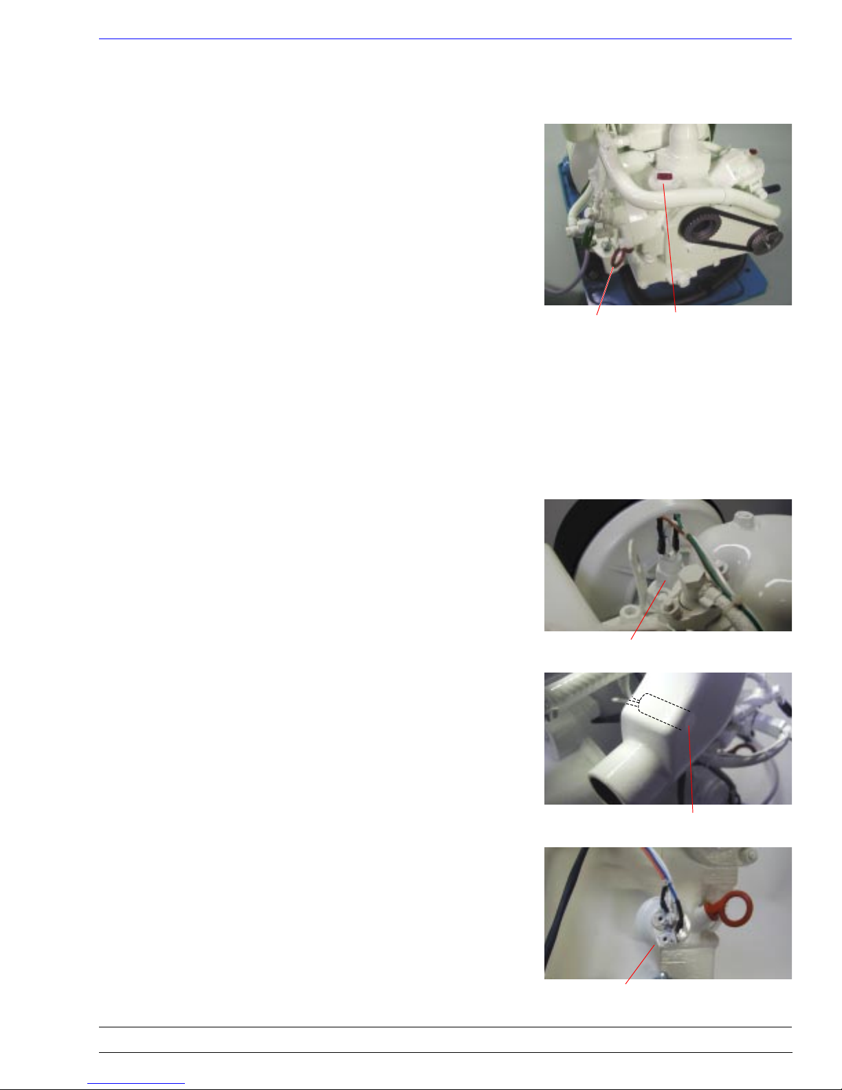
The Raw Water Pump (rear half of 15/1) draws outside raw water
from the sea cock and strainer and pushes it through a hose
(16/13), into the Heat Exchanger (16/1). As it passes through the
Heat Exchanger it absorbs heat from the fresh water coolant.
The raw water is then discharged into the Exhaust Elbow where it
is sprayed on the hot exhaust gases to cool them. It then flows
with the exhaust gas into the typical “wet marine” exhaust system.
CAUTION
Whenever the engine is cranked, the Raw Water Pump
continues to pump water through the raw water system.
With continued cranking, it is possible to fill the Exhaust
Percolating Muffler, the Exhaust Hose, the Exhaust Elbow,
and if the Exhaust Valve is open, the engine combustion
chamber, with raw water. If the raw water is sea water, the
damage to the engine can be severe. If this ever happens,
corrective action must be taken at once. If the engine will
not start within 7 to 10 seconds, stop cranking!
Raw Water Inlet
Heat Exchanger Inlet
Raw Water Outlet
Exhaust Elbow Inlet
6
16710 SW 72nd • Portland, Oregon 97224 • (503) 624-7118
Entec West, Inc.
Page 7
System Descriptions EW-4200D
LUBRICATION
After the final test at the factory, the oil is removed from the
engine to comply with Federal shipping laws. Therefore, it is
necessary to put oil into the engine before attempting to start it.
The crankcase capacity is approximately 1.25 liters (1.33
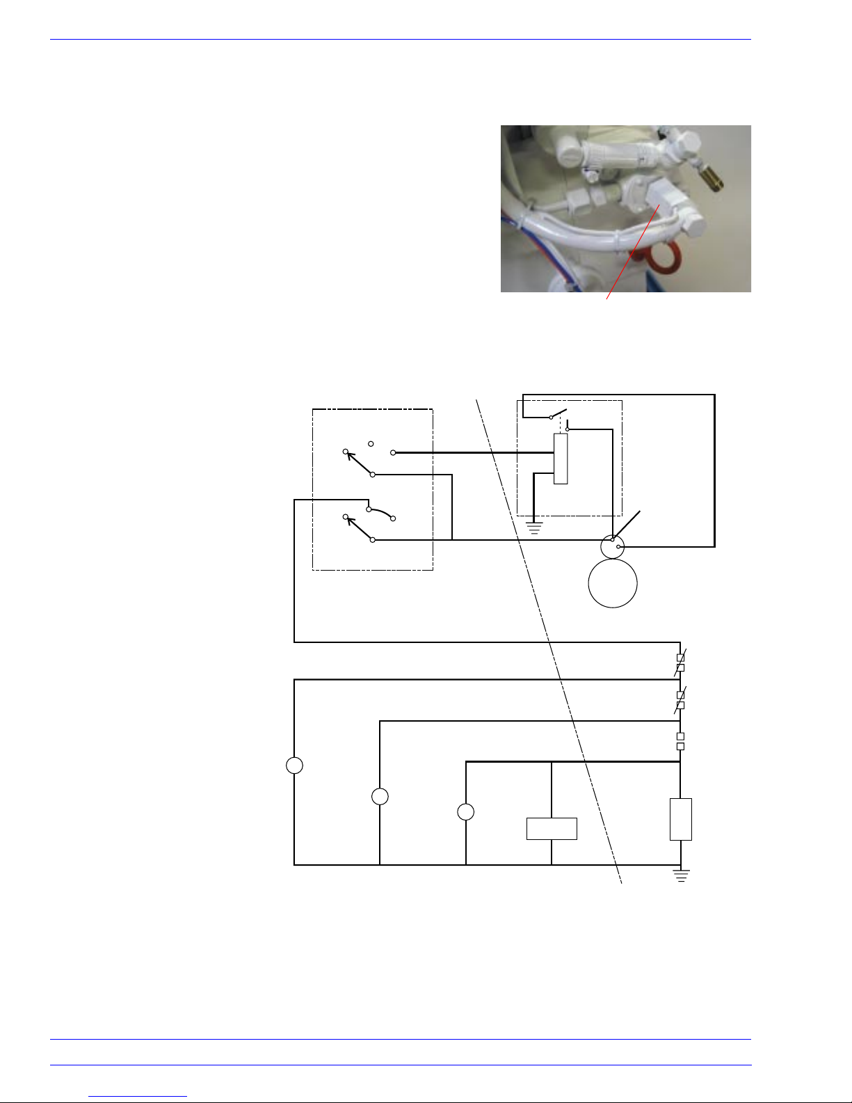
quarts). The oil Dipstick has two marks on it (3/12). The upper
one is the “full” mark and the lower one indicates “add oil.” The
distance between the two marks is equivalent to approximately
0.18 liters (0.19 quarts). NEVER, NEVER, overfill the engine.
The best operating condition will be with the oil level slightly
below the “full” mark.
The oil fill cap is located on the top of the gear cover (3/11).
There is no oil filter on this engine.
The American Petroleum Institute classifies oil according to
application. Within these classifications there are good, better,
and outstanding oils for use in small diesel engines. We recommend a product marketed by Chevron Oil Co. called DELO-400.
We suggest a multi-viscosity 15W-40 weight for all season use.
Dipstick Oil Fill Cap
ENGINE CONTROL SYSTEM
The remote run/stop control for the engine is accomplished
through the use of a special high pressure valve. When the valve
is energized, it closes and the injection pump is allowed to
deliver high pressure fuel to the injector. The engine is further
controlled by three switches: water temperature, exhaust temperature, and oil pressure.
Water Temperature Switch. The water temperature switch
(12/47) is located on the cylinder head. It is normally closed and
will open when the engine coolant temperature rises to 185
degrees F. It will close again at approximately 160 degrees F.
Exhaust Temperature Switch. The exhaust temperature switch
(16/19) is located in the casting wall of the Exhaust Elbow. It is
normally closed and will open when the internal temperature of
the elbow rises to 185 degrees F. It will close again at approximately 160 degrees F.
Oil Pressure Switch. The oil pressure switch (2/5) is mounted
on the left side of the engine, looking at the handcrank end. It is
normally open and is set to close at 15 psi. It will open if the oil
pressure falls below 12 psi.
Water Temperature Switch
Exhaust Temperature Switch
Entec West, Inc.
Oil Pressure Switch
16710 SW 72nd • Portland, Oregon 97224 • (503) 624-7118
7
Page 8
System Descriptions EW-4200D
ENGINE CONTROL SYSTEM (cont.)
Fuel Control Valve. The Fuel Control Valve (6/18) is mounted
on the Fuel Injection Pump. It is normally de-energized. In the
de-energized position, the high pressure output from the Injection Pump is bypassed into the fuel return line. The injector does
not receive fuel.
Fuel Control Valve
Off/Run/Start Switch.
+12 volts is taken from the
starter post, through the
wiring harness (red wire),
Panel Harness
547-06-13
Off/Run/Start Switch
547-644H
Extension Harness
547-06-12
and applied to the terminals
of the Off/Run/Start switch
located on the control panel.
Run Position. When the
Off/Run/Start switch is
moved to the Run position,
+12 volts is applied back
through the harness (green
wire) to one side of the
water temperature switch.
This switch is normally
closed, so the +12 volts will
pass through the switch to
the exhaust temperature
switch, and also through the
harness (brown wire) to the
water lamp. The water lamp
will illuminate because the
engine coolant temperature
Water
L
547-50-03
Exhaust
L
547-50-03
is below 185 degrees F.
Since the exhaust tempera-
ture switch is also closed,
the +12 volts goes to the oil
pressure switch, and also through the harness (orange wire) to
the exhaust lamp. The exhaust lamp will illuminate because the
exhaust temperature is also below 185 degrees F. The oil pressure switch is normally open, so the +12 volts will stop at this
point with the two lamps illuminated.
White
Oil
L
547-50-03
Red
Green
Brown
#87
#86
#85
Start Relay
547-66-200
Start Motor
547-3681
Orange
Blue
Engine Harness
547-47-01
#30
HourMeter
555-T4-1E45
+12 Volts
from Battery
#4 Gauge Min.
White
Black
Water Temp
555-00-53
Exhaust Temp
555-00-54
Oil Press
237-40-07
Fuel Control
Valve
257-04-82
8
16710 SW 72nd • Portland, Oregon 97224 • (503) 624-7118
Entec West, Inc.
Page 9
System Descriptions EW-4200D
ENGINE CONTROL SYSTEM (cont.)
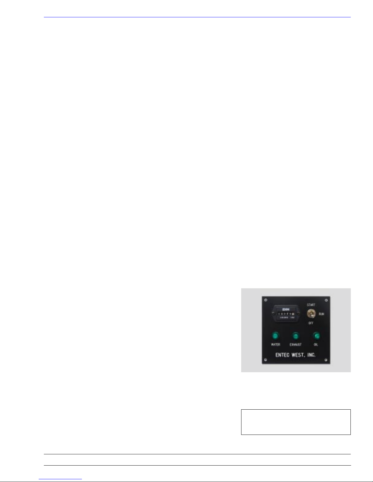
Start Position. Moving the Off/Run/Start switch to the Start
position allows +12 volts to flow the same as in the Run position. In addition, +12 volts flows through the harness (white
wire) to the start relay (located on the top of the generator, by
the start motor). With +12 volts applied, the relay energizes and
the internal contacts close. The start motor begins to crank the
engine and the internal oil pump begins to develop oil pressure
and “floods” the bearings with oil.
When the oil pressure reaches 15 psi, the oil pressure switch
closes. +12 volts then goes to the Fuel Control Valve, energizing
it, and back to the panel through the harness (blue wire) to
illuminate the oil lamp.
As soon as the Fuel Control Valve is energized, high pressure
fuel is delivered to the injector, and the engine will start. The oil
pump continues to deliver oil to the bearings and the oil pressure
switch will stay closed. The hourmeter on the panel will also
operate.
SAFETY STOPS
As described previously in the Off/Run/Start switch sequence,
the entire switch and control system operates in series. If any
one of the three switches opens, the circuit is broken and the
engine will stop. Turning off the ship’s 12 volt power will also
stop the engine.
Understanding the Lamps
All Lamps Out. If the water temperature switch opens, because
of high coolant temperature, the engine will stop and all of the
lamps will go out.
Exhaust and Oil Lamps Out. If the exhaust temperature switch
opens, because of high exhaust temperature, the engine will stop
and the exhaust and oil lamps will go out.
Oil Lamp Out. If the engine oil pressure falls below 12 psi, the
oil pressure switch will open. The engine will stop and the oil
lamp will go out.
CAUTION: If battery power is
turned off, the engine will stop!
Entec West, Inc.
16710 SW 72nd • Portland, Oregon 97224 • (503) 624-7118
9
Page 10
Operation EW-4200D
STARTING THE ENGINE FOR THE FIRST TIME
Read and familiarize yourself with the description of the Engine
Control System before attempting to start the engine (see
System Descriptions).
Although the engine is shipped with the Injection Pump, high
pressure line, Injector, and Fuel Transfer Pump filled with fuel,
it is necessary to draw fuel from the vessel’s tank to charge the
primary filter and transfer pump fuel line. The following procedure will accomplish this and verify the system performance.
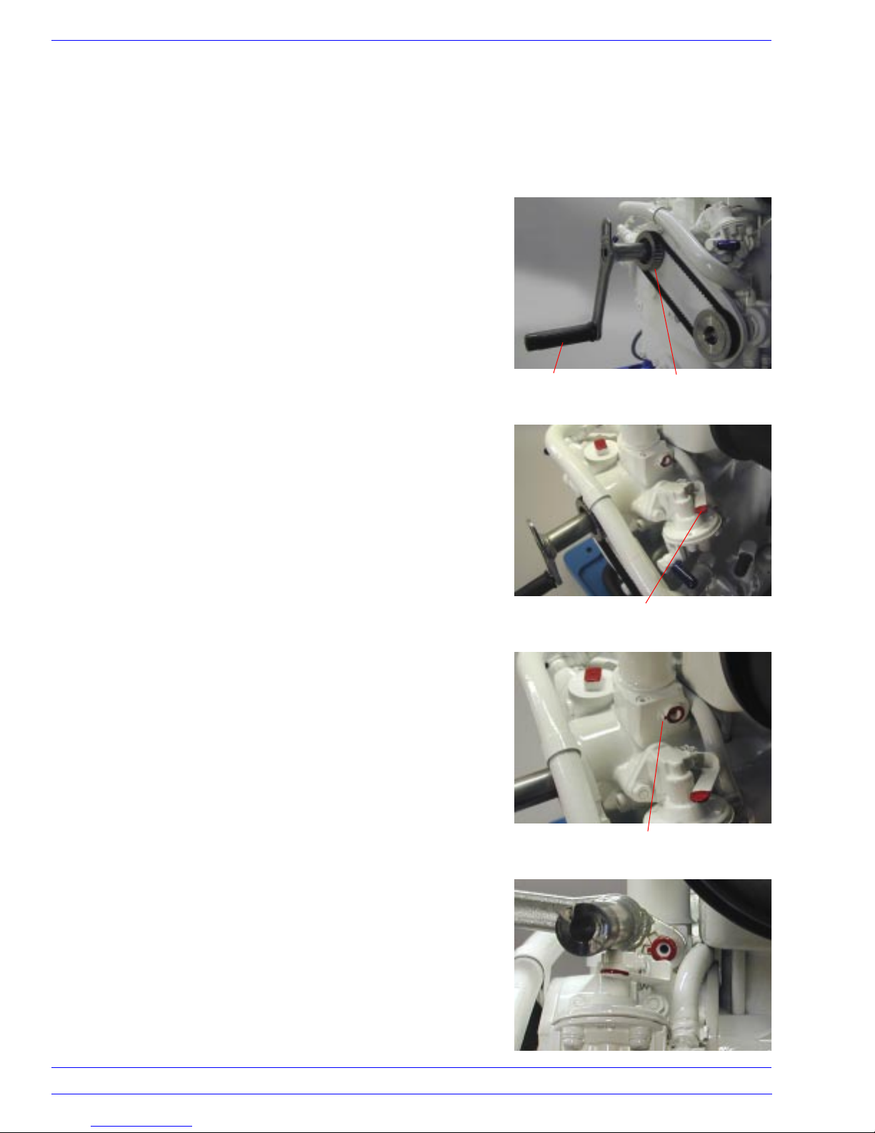
1. Place the Off/Run/Start switch in the Run position.
2. Place the Handcrank (20/6) into the Camshaft (3/45), located
in the center of the Water Pump Drive Pulley. Rotate the crank
counterclockwise until you feel hard resistance from the
compression stroke.
3. Find the Fuel Transfer Pump (3/50) on the upper right side of
the engine. Pump the Priming Lever for 20 to 30 strokes, in
order to supply vessel fuel to the engine. Use the full movement of the lever. Only the last few degrees of motion will
actually pump fuel.
Handcrank
Water Pump Drive Pulley
4. Locate the Compression Release Shaft (3/39) above the drive
pulley. Note the small pin on the short shaft (the Compression
Release Shaft) protruding from the side of the cam follower
assembly. The pin should point toward the front of the engine
(the 9 o’clock position) to indicate normal compression
operation.
5. Place the Handcrank over the small pin on the Compression
Release Shaft. Use the first slot in the tab on the Handcrank
(it is the only slot that will fit in the 9 o’clock position).
Rotate the pin and shaft to the 10:30 position (the Handcrank
handle will stop against the valve cover). This locks the intake
valve open and in the decompression mode — the engine will
not return to the compression mode.
Priming Lever
Small pin on the
Compression Release Shaft
10
16710 SW 72nd • Portland, Oregon 97224 • (503) 624-7118
Entec West, Inc.
Page 11
Operation EW-4200D
STARTING THE ENGINE FOR THE FIRST TIME
(Continued)
CAUTION: CLOSE THE SEA COCK.
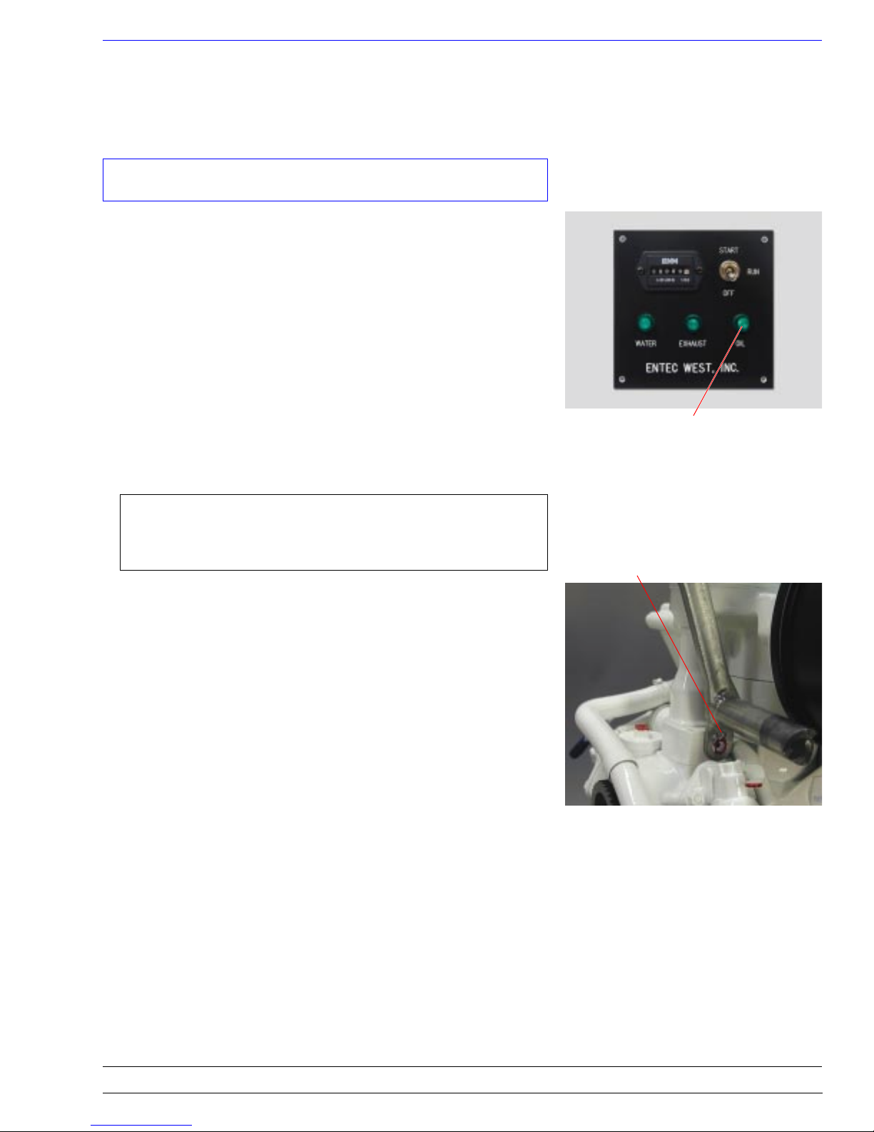
6. Put the Handcrank back into the Camshaft and rotate it
counterclockwise. Crank fast enough to develop oil pressure.
This will close the Oil Pressure Switch and make the oil light
on the control panel come on. When this happens, power is
applied to the Fuel Control Valve (6/18) and the Injection
Pump is energized. Each time the rotation passes the position
for fuel injection, the Injector will make a pronounced
squeeking noise as it sprays fuel into the combustion chamber.
If you do not hear the squeek, repeat the priming sequence
(step 3) and try again.
7. The next task is to return the engine to the normal compression mode. This will happen automatically when the Compression Release Shaft is rotated to unlock the intake valve.
Oil Light on Control Panel
NOTE: This automatic feature will not function when
the small pin points anywhere between the 9 o’clock
and 12 o’clock positions.
Use the second slot of the tab on the Handcrank to rotate the
Compression Release Shaft to a position just past twelve
o’clock (once again, the Handcrank will stop against the valve
cover). This will program the Compression Release to index
one step for each rotation of the camshaft. The Compression
Release Shaft will index all the way around to the 9 o’clock
position in approximately seven revolutions of the camshaft.
8. OPEN THE SEA COCK.
9. Put the Off/Run/Start switch on the control panel in the Start
position. The engine will spin freely until the Camshaft
completes the seven turns. On the seventh turn the Compression Release will reset itself to normal compression mode.
When this happens, the engine will start. Quickly release the
start switch and set it to the Run position.
All three lights on the control panel should be illuminated and
will remain so until the engine is stopped by the operator, or
the safety system detects a problem (26/0).
Handcrank – second slot
Entec West, Inc.
16710 SW 72nd • Portland, Oregon 97224 • (503) 624-7118
11
Page 12
Operation EW-4200D
NORMAL ENGINE STARTING
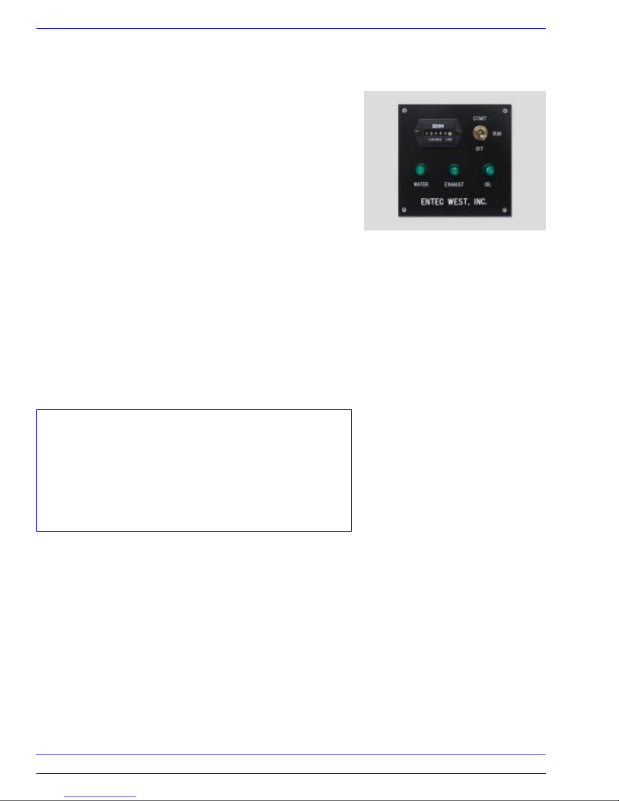
1. Place the Off/Run/Start switch on the control panel in the
Start position. This feeds +12 volts to the Start Relay (located
near the start motor) causing it to energize. The heavy internal
contacts of the Start Relay close, and +12 volts is applied to
the Start Solenoid on the Start Motor.
The Start Motor cranks the engine, and two things happen
simultaneously: the Oil Pump in the engine starts to pump oil
into the galley; and oil flows to the bearings, lubricating them.
The oil pressure rises from zero to the operating pressure. At
15 psi the Oil Pressure Switch closes and the +12 volts passes
through the switch to the Fuel Control Valve energizing it, and
to the oil light causing it to illuminate.
As soon as the Fuel Control Valve is energized, high pressure
fuel is delivered to the injector pipe and thus to the Injector. If
the engine is operating normally, it will start in 3 to 7 seconds.
2. When it starts, quickly release the Start Switch and set it to
the Run position. The control panel will show a “green board”
(all lights green) and will remain green until the engine is
stopped by the operator, or the safety system detects a
problem (26/0).
Control Panel
CAUTION: If the engine has been properly maintained,
and all of the external support systems, including raw
water feed, fuel feed, battery power, etc., are functioning
properly, the engine will normally start within 3 to 7
seconds. If the engine does not start within this time
period, STOP and try only one more cranking attempt.
DO NOT CONTINUE CRANKING ! ! !
12
16710 SW 72nd • Portland, Oregon 97224 • (503) 624-7118
Entec West, Inc.
Page 13
Operation EW-4200D
GENERATING A.C. POWER
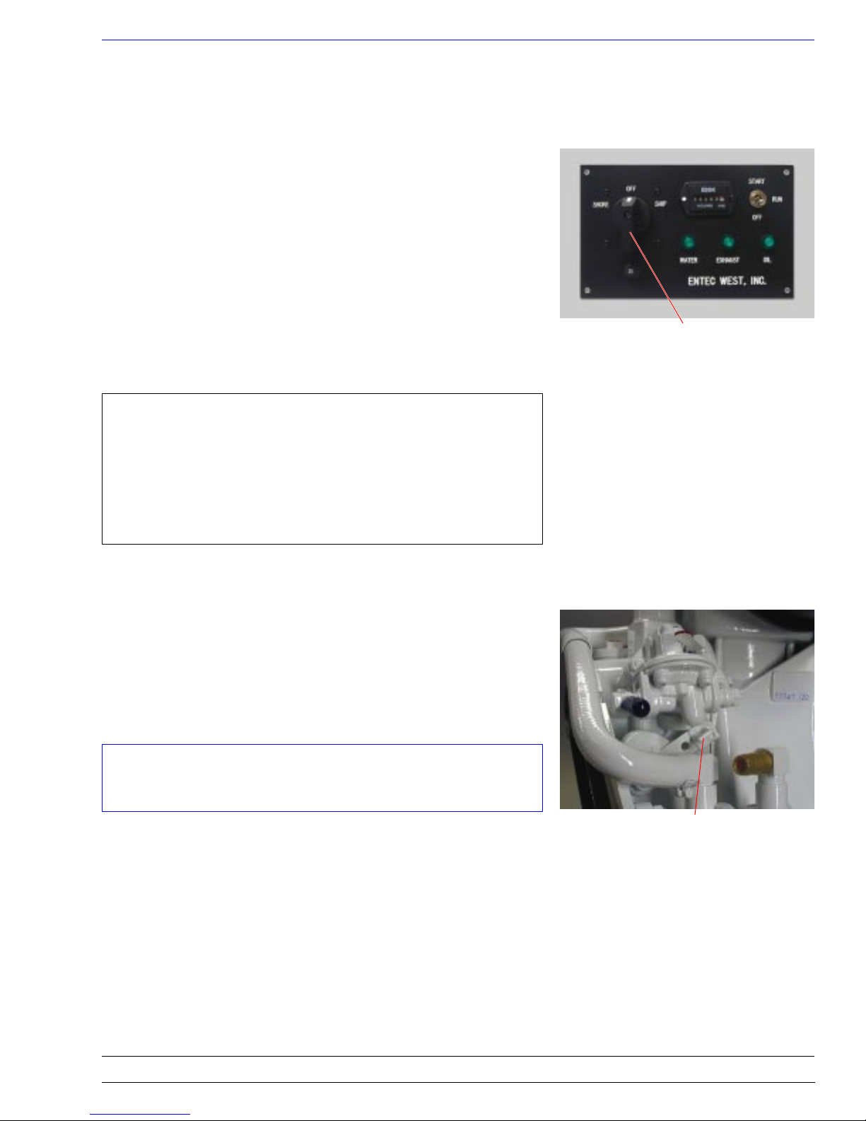
Starting the Engine
Start the engine and let it warm up for two or three minutes.
Turn the ship’s A.C. load off at the main breaker panel. Now
turn the “Ship/Shore” switch to the SHIP or GEN position. Turn
on some of the panel breaker switches until the generator is
lightly loaded. Give the engine a few minutes to reach operating
temperature, then load it to your electrical requirements.
Stopping the Engine
Before stopping the engine, switch off the individual A.C. loads
and turn the “Ship/Shore” to the OFF or SHORE position. Let
the engine run without load for three to five minutes so it can
cool down.
NOTE: If the unit has been operating under heavy load
and stopped without a cooling off period, residual heat
from the lower end of the engine can migrate upward and
trip the Water Temperature Switch. If this happens, the
alarm system will prevent re-starting the engine until it
has completely cooled down.
Ship/Shore Switch on
Optional Control Panel
EMERGENCY STOP
If the engine cannot be stopped by the remote control system it
can be stopped manually with the Throttle Control (5/11). The
control arm is located below the Fuel Transfer Pump. Rotate the
arm clockwise to the stop and hold it there until the engine
comes to a complete stop. Return the arm to the full counterclockwise position after the engine stops.
CAUTION: This is not a speed control. DO NOT!
DO NOT! attempt to adjust this control.
Throttle Control Arm
Entec West, Inc.
16710 SW 72nd • Portland, Oregon 97224 • (503) 624-7118
13
Page 14
Operation EW-4200D
MANUAL HAND STARTING
Manual hand starting is similar, but not identical to, Starting the
Engine for the First Time.
1. Follow steps 1 through 8 in Starting the Engine for the First
Time.
2. Put the Off/Run/Start switch in the Run position.
3. Place the Handcrank in the Camshaft. Position your body to
the front of the unit. Grasp the handcrank in your left hand
and gently rotate it counterclockwise for two or three turns.
This action will pre-lube the bearings.
3. Now crank energetically to build up inertia in the moving
parts of the engine. Each time the handcrank makes one
revolution, the compression release will automatically index
one step. On the seventh turn the Compression Release will
reset itself to normal compression mode. Do not slow down.
Your body energy added to the inertia will help you pull
through the compression stroke and create ignition. When this
happens, the engine will start.
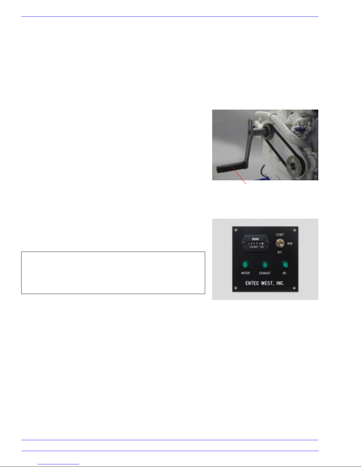
Handcrank on
Camshaft
All three lights on the control panel should be illuminated and
will remain so until the engine is stopped by the operator, or
the safety system detects a problem (26/0).
NOTE: Do not be afraid of the Handcrank. It will not backfire. It will automatically disengage itself from the Camshaft.
We suggest you try the manual start method for the first time
when the engine is warm from running.
Control Panel
14
16710 SW 72nd • Portland, Oregon 97224 • (503) 624-7118
Entec West, Inc.
Page 15
Periodic Maintenance EW-4200D
CHANGING THE OIL
For best engine life, the oil should be changed every 75 to 100
hours, or annually, which ever occurs first.
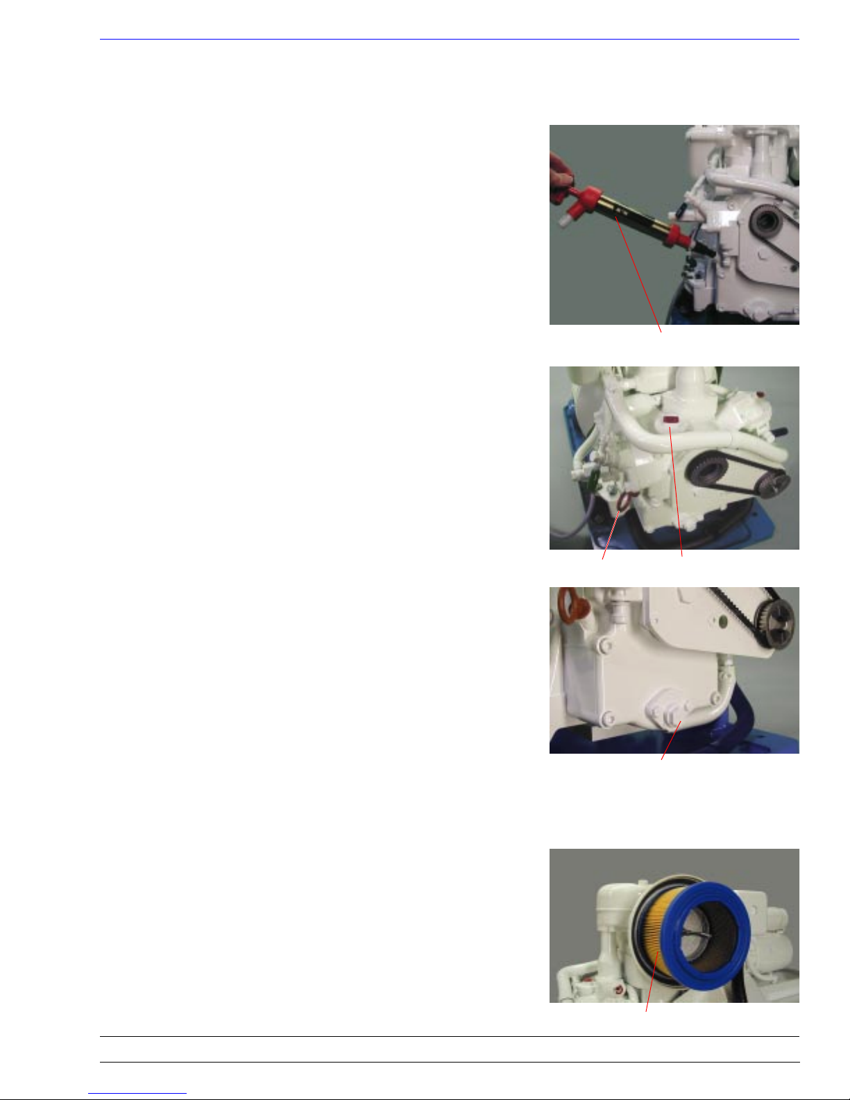
The unit comes with a dipstick type oil pump for changing the
oil. Start and run the engine for several minutes to get the oil
warm. Stop the engine and remove the Dipstick. Insert the oil
Dipstick Pump tube as deep into the engine as possible. Suck the
oil out using the pump, and dispose of it according to EPA
regulations.
Dipstick Oil Pump
Remove the oil Fill Cap and add one quart of approved oil.
Replace the oil Fill Cap and Dipstick. Start the engine and let it
run for one to two minutes. Stop the engine and check the level
on the oil Dipstick. Adjust the level as necessary.
With practice, the amount of old oil removed will be just the
right amount, so that adding one quart of new oil will bring the
level up to the correct level.
Although there is an oil Drain Plug on the engine (3/15), it is too
low on the generator to provide easy access for draining.
Installation of an adapter at this location for drain pumps, etc.
will automatically void the warranty.
AIR CLEANER
The Air Cleaner housing contains a dry element filter. Remove it
and shake the accumulated dirt from it each time you change the
oil. The element should be replaced every 250 to 300 hours.
Dipstick Oil Fill Cap
Drain Plug – DO NOT USE!
Entec West, Inc.
Air Cleaner Element
16710 SW 72nd • Portland, Oregon 97224 • (503) 624-7118
15
Page 16
Periodic Maintenance EW-4200D
VALVE ADJUSTMENT
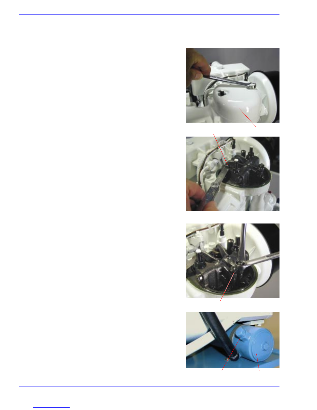
The Intake and Exhaust Valve (8/4 & 11) clearance is set by the
adjustments on the Rocker Arms (8/23 & 24). The adjustments
must be made when the engine is at ambient temperature. Using
a 13mm wrench, remove the two nuts and gaskets (8/44 & 41)
on top of the Valve Cover (8/40). Gently lift the Valve Cover off
the Cylinder Head.
Put the Handcrank into the Camshaft and rotate it counterclockwise until you feel hard resistance from compression. Check the
gap between the valve stem and the anvil on the rocker with a
feeler gauge. There should be a very slight drag with a .006 inch
gauge.
If it is not correct, loosen the locknut (8/24) with an 11mm
wrench. Adjust the clearance with a screwdriver in the slot of the
adjustment screw (8/23). Hold the screw in position while
tightening the locknut. Re-check the clearance. Both valves
require the same clearance.
The valve clearance should be checked every 250 to 300 hours,
or annually.
Rocker Arm Anvil
Valve Cover
HEAT EXCHANGER
The Heat Exchanger (16/1) utilizes cupro-nickel tubes. They
should last for the life of the generator. However, the tubes can
become clogged with silt and sea water contamination. To clean
the tubes, remove the End Caps and gaskets on each end. Clear
the tubes by pushing a stiff rod through them. Do not use a rod
diameter greater than 11/64⬙.
The Heat Exchanger contains a sacrificial Zinc Insert in a plug
(16/2). Examine it when checking the valve clearance and
replace, as necessary. The Zinc is a readily available Type 1A.
16
16710 SW 72nd • Portland, Oregon 97224 • (503) 624-7118
Locknut
Plug with
Zinc Insert
Heat Exchanger
End Cap
Entec West, Inc.
Page 17
Periodic Maintenance EW-4200D
RAW WATER PUMP MAINTENANCE
The Impellers and Shaft Seals are normal wear items and do not
have a “typical” life span. As such, it is common to change them
on a regular basis; such as, with every other oil change. The
condition of the raw water, ie: silt content, contamination, etc.,
contributes to the deterioration of these components and the
frequency at which they should be replaced. The Impellers for
both pumps are identical, but the Shaft Seals are different.
An exhaust temperature light going out (alarm) can indicate
insufficient flow and therefore a worn raw water Impeller. The
appearance of insufficient flow at the exhaust outlet can also
suggest a worn raw water Impeller.
A falling coolant level, with no apparent leaks, can indicate a
leaking raw water pump Seal (21/10). The engine coolant can
follow the raw water pump shaft (21/2) through a worn Seal into
the raw water pump chamber. Once in the raw water pump, the
coolant will be pumped overboard with the waste raw water.
Impeller Removal
If it is necessary to replace the Seals or Impeller (21/4) in the
raw water pump, follow these steps:
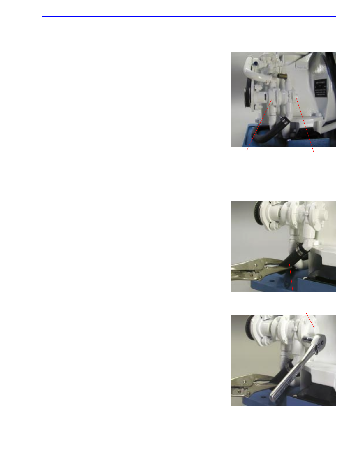
1. Clamp the raw water Outlet Hose (16/13) with vise grip pliers.
This will prevent raw water from draining into the drip pan.
2. Remove the four screws (21/14) from the End Cap using a
7mm socket and 1/4⬙ drive ratchet. A box or open end wrench
can also be used, but not as conveniently. Pull the End Cap
(21/5) off the pump. Remove the paper Gasket (21/6).
4. Grip the Impeller with long nose pliers and pull the Impeller
and Shaft assembly (21/2 & 4) out of the pump body. Remove
the screw (21/13) from the Impeller and slide it off the Shaft.
5. Clean the deposits off the Shaft with 400 grit paper.
Engine Cooling
Pump
Raw Water Outlet Hose
Raw Water
Pump
End Cap
Impeller Installation
1. Remove the screw from the new Impeller. Lubricate the Shaft
with light grease, put the new Impeller on the Shaft and insert
the screw.
2. Lubricate the Impeller, vanes, front, back, and Shaft, with
light grease. Insert the Shaft into the pump body and fold the
vanes as necessary to insert the Impeller into the pump.
3. Lubricate both sides of a new Gasket and place it onto the
body. Align the End Cap with the body and press it onto the
Shaft. Install the screws and tighten them evenly.
DO NOT OVER TIGHTEN THE SCREWS!
Entec West, Inc.
16710 SW 72nd • Portland, Oregon 97224 • (503) 624-7118
17
Page 18
Theory of Operation EW-4200D
HOW COMPRESSION IGNITION WORKS
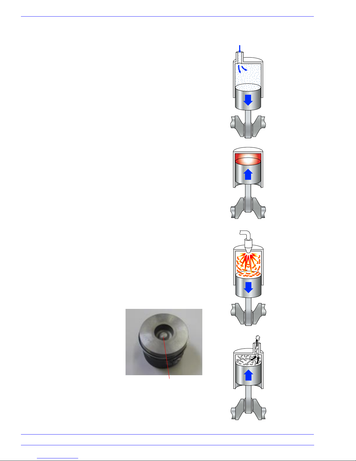
In a four cycle engine, four strokes of the piston are required to
complete one cycle; Intake, Compression, Power, and Exhaust.
With only one stroke providing power, a heavy rotating flywheel
keeps the crankshaft turning through the other three strokes.
Intake Stroke. When the intake valve (8/4) is open and the
piston (7/15) is pulled downward in the cylinder (7/27), air is
drawn into the cylinder and fills the volume above the piston
(intake stroke).
Compression. At the bottom of the stroke, the intake valve
closes and the piston is pushed up toward the cylinder head. The
trapped air is compressed into a small volume (the cup in the top
of the piston) and heat is generated due to this compression. The
smaller the volume the more heat is generated. When the heat in
the compressed air can be concentrated in the piston cup so that
it cannot escape into the cylinder walls, etc., the temperature of
the compressed air will get very high.
Power Stroke. At the top of the compression stroke the fuel is
sprayed into the very hot compressed air and ignites. As the fuel
burns, the hot combusted gases expand, forcing the piston down.
The force applied to the top of the piston in the downward
motion is converted into rotary motion by the connecting rod
and the crankshaft. This is called the power stroke.
Intake
Compression
Exhaust Stroke. At the bottom of the power stroke, the exhaust
valve (8/11) is opened and as the piston comes back up, the
burned gases are expelled into the exhaust elbow (16/6). When
the piston is back at the top, the exhaust valve closes, the intake
valve opens, and the whole cycle is repeated. This is called a
four cycle engine.
Piston Cup Design. The unique
“cup” design in the top of the
piston helps to contain the “heat
of compression,” and is what
gives our engine the ability to
start without the aid of glow
plugs and/or heaters. It also
makes it possible to start the
engine with a handcrank.
Piston Cup
Power
Exhaust
18
16710 SW 72nd • Portland, Oregon 97224 • (503) 624-7118
Entec West, Inc.
Page 19
Theory of Operation EW-4200D
Injection Pump and Injector. The injection pump is like a
miniature piston and cylinder with a special valve. When the
miniture piston is pulled down, fuel is drawn into the cylinder.
When the piston is pushed up, the fuel is forced through a
special check valve and into the high pressure pipe (11/11)
leading to the injector. The pipe is full of fuel, so whatever
quantity is forced into the pipe at the injection pump end, must
come out at the injector end and into the injector. The injector is
a special combination check valve and atomizer that will open
when the pressure in the pipe reaches 2,900 psi. The injector has
a tip with tiny holes that causes the fuel to be sprayed as a fine
mist, or atomized. At the top of the compression stroke the fuel
is sprayed into the very hot compressed air and ignites.
Ignition Temperature. To reach ignition temperatures during
the compression stroke, the piston must travel at a fast enough
speed to prevent the loss of heat. A weak battery, or dirty cable
terminals, etc. will not turn the engine fast enough to prevent the
heat loss.
The same is true for hand cranking speed. A timid hand cranker
will never start the engine by hand.
Fuel Efficiency. The injection pump is controlled by the engine
governor (7/12 & 13) and throttle control (5/1 –13) system that
tells the injection pump how much fuel should be delivered to
the injector. This quantity is established every single time the
engine reaches the end of the compression stroke. You can think
of the fuel flow as a series of fuel “slugs,” happening at a rate of
1,800 times per minute for our 60 cycle generator. The injection
pump always delivers just the right quantity fuel that the governor demands, to produce the horsepower needed, to make the
exact amount of electrical power the vessel needs at any given
point in time.
If the generator load was 30 amps, then calculate 0.4 gallon per
hour fuel consumption, divided by 60 minutes per hour, and
divide that by 1,800 injection pulses per minute, and you can get
an idea of how small each “slug” of fuel is.
For Example: 231 cubic inches of fuel in a gallon, multiplied by
0.4, divided by 60, then divided by 1800, equals 0.00086 cubic
inches of fuel per “slug”.
231 0.4 60 1800 0.00086
If the load was 10 amps, the “slug” would be approximately 1/3
of 0.00086 cubic inches, or 0.00029 cubic inches.
Entec West, Inc.
16710 SW 72nd • Portland, Oregon 97224 • (503) 624-7118
19
 Loading...