

Ensy AHU-300 HV, AHU-300 HH User Manual And Installation Manual
User manual and
Installation Guide
AHU-300 HV
AHU-300 HH

393870-2 Rev 0: 11.07.2018 BBV
We reserve the right to change technical data without notice. http://www.ensy.no Page 1
393870-2 Rev 0: 11.07.2018 BBV
We reserve the right to change technical data without notice. http://www.ensy.no Page 2
User manual. Page 1 to 13
(Front page and pictures on pages 1-5 shows AHU-300 HV)
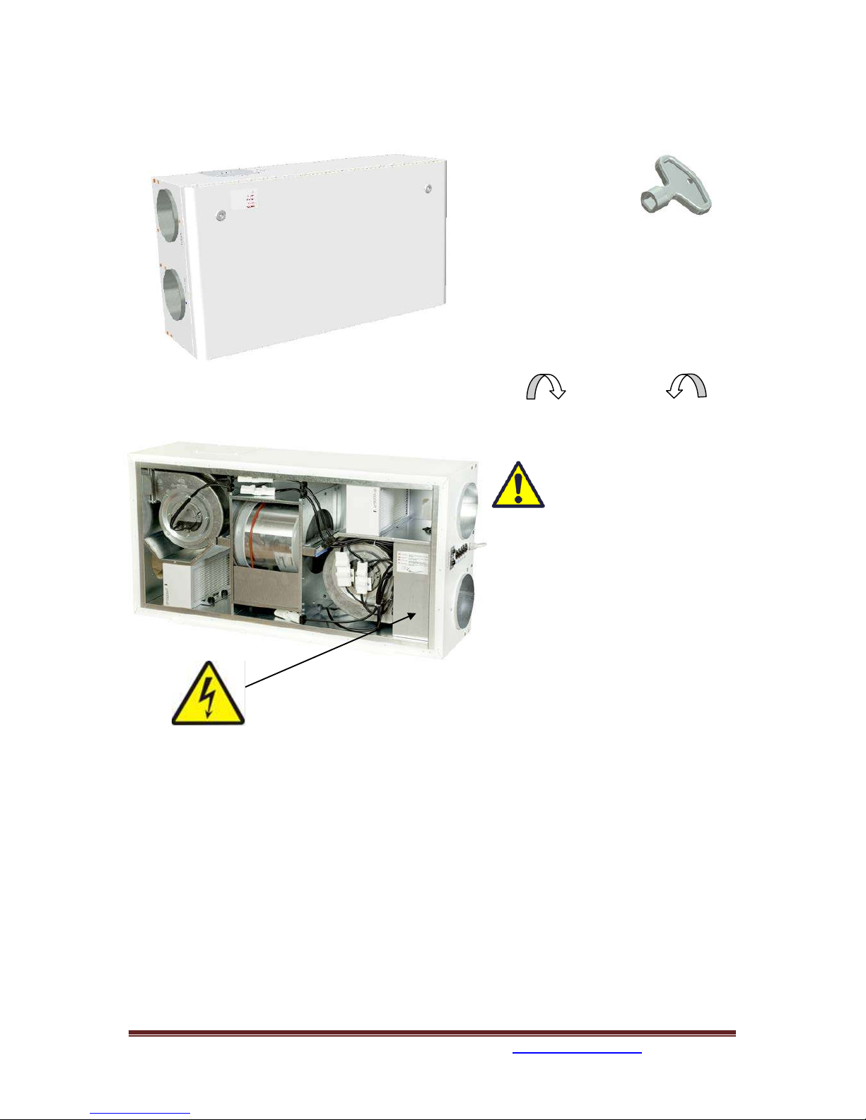
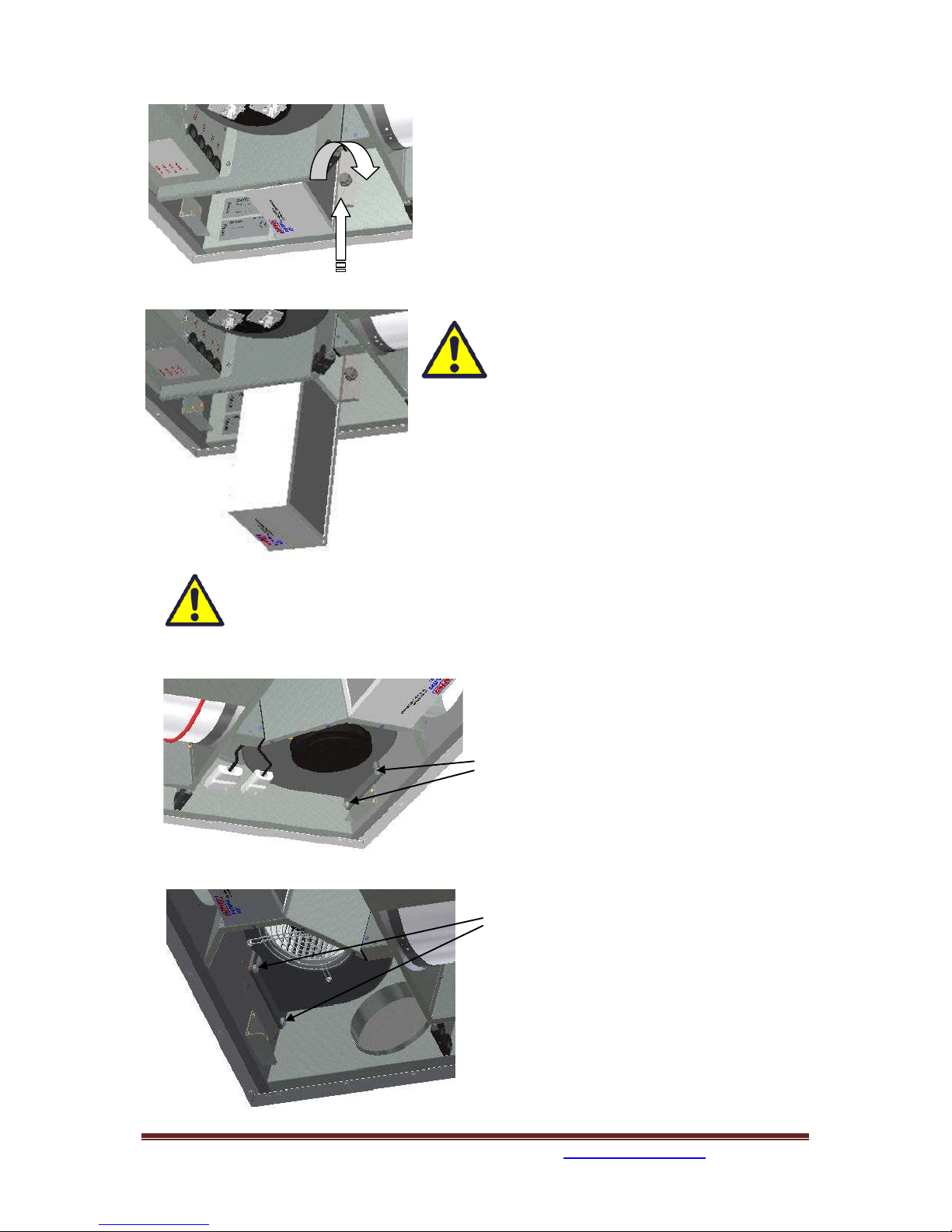
To
open the front hatch
you will find a key for the
quarter turn latches in
the folder together with
the following documents.
Keep this key in a place so it is out of reach
for children.
To open the locks, turn the key toward the
center of the unit.
Left latch Right latch
To operate this product
people should have
necessary skills, or under the
supervision of a qualified person.
Children should be told to not play
with the appliance.
Before any access into the electrical connections boxes, power must be
disconnected by pulling out the plug from the socket.
It is only allowed for authorized persons to enter into the electrical connection boxes. (Sketch shows
AHU-300 HH)
If any electrical components are damaged, they must be replaced by the manufacturer, dealer or a
qualified person in order to avoid dangerous situations.
393870-2 Rev 0: 11.07.2018 BBV
We reserve the right to change technical data without notice. http://www.ensy.no Page 3
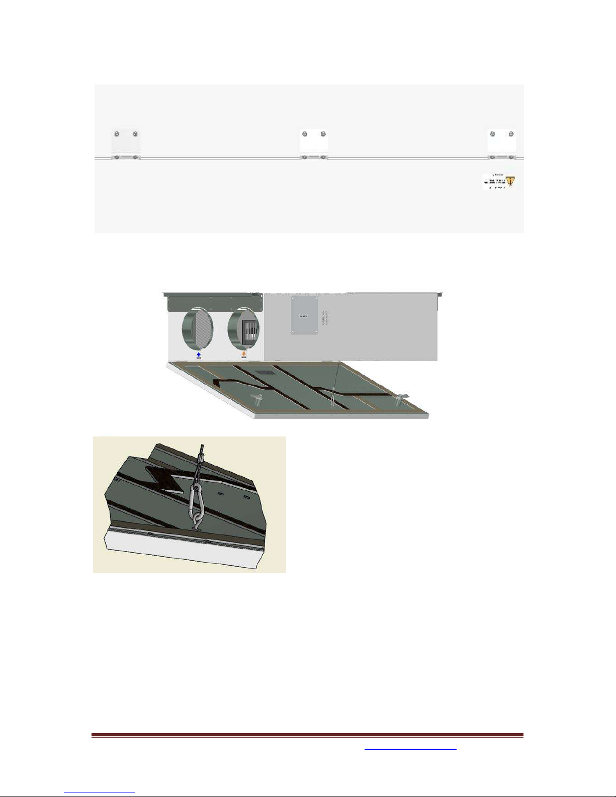
The hatch has three hinger that holds it permanently to the housing. If the unit is placed high under a
ceiling, then is mandatory to get help from another person to take down the hatch. It can be done by
unscrewing 6 pcs of screws from the housing or front hatch.
Th
e safety wire can be removed from inside of the front hatch so that the hatch can be
opened or removed. The safety wire must be reinstalled before the hatch closes.
To close, after putting the hatch back on place, turn the latches the opposite way. You may use some
pressure towards the hatch to close it.
393870-2 Rev 0: 11.07.2018 BBV
We reserve the right to change technical data without notice. http://www.ensy.no Page 4
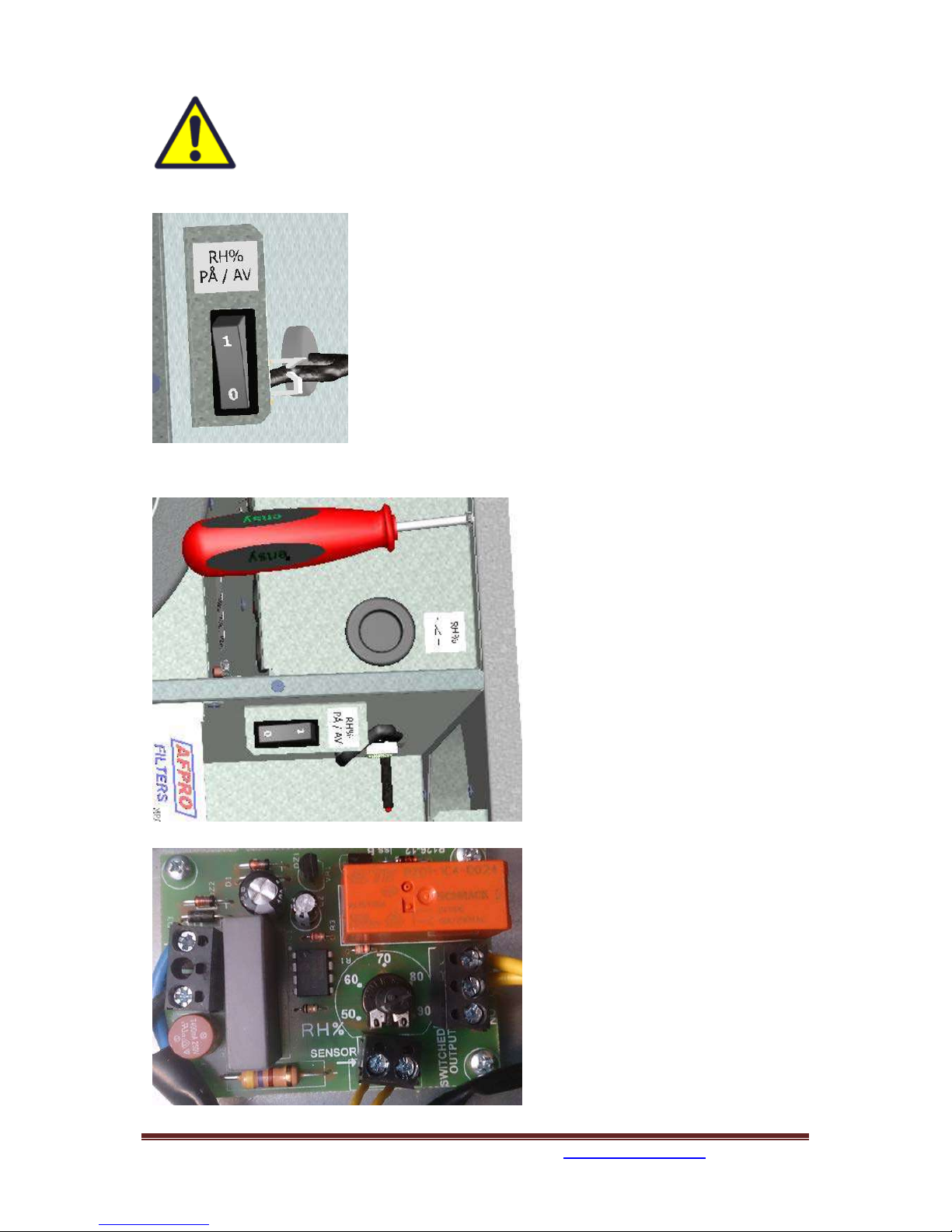
Adjustment of the unit.
A
humidity sensor is, from factory, mounted inside the unit. It is set to “0” that
means it is set to not active.
No
te!
This switch is not used on units produced before february 2015.
A
fter startup, where the unit is placed into a new building with high
humidity, you can let this humidity sensor be turned off for a period
to avoid the full speed of the fan at night. To get the humidity
sensor to operate as intended, you need at one time to put it active.
Than you need to set the switch in position "1".
I
f the ventilation unit is placed in a house without high humidity,
you should switch to position "1" after you putting ventilation unit
into operation.
T
his switch will also affect any extra external humidity sensor that is
plugged into the device.
Adjusting the humidity sensor.
If it is necessary to adjust the sensitivity
of the humidity sensor then you just can
remove the black plug and you then can
see the adjusting knob and the RH%
scale.
Note! This black plug is not on
units produced before february
2015.
If bad light condition, it may be easier to
remove the cover so that you easier
seethe RH% scale.
The sensor is set to 80% RH from factory.
If you do adjustments, this only affect
the sensor integated inside the unit.
The sensitivity for the integrated sensor
you can adjusted from 50% (low) to 90%
(high) in accordance to what are the
needs. The arrow points the value
chosen.
If you have a second external sensor that
means you need to adjust that one from
its settings.
Replace the cover and / or plug after
finish adjusting.
393870-2 Rev 0: 11.07.2018 BBV
We reserve the right to change technical data without notice. http://www.ensy.no Page 5
Replacing the filter.
The filters should be replaced every 6. 9. or 12. months.
Before the filters can be removed, you have to unscrew a
little bit two crews for each locking bracket. Push the
bracket away from you to release the filters.
Should than be extracted without use of any tools.
To guarantee optimal properties of the
ventilation unit, use the original filters from
EnSy. The use of spurious filters will limit the
warranty on the product
Ensy art number for filter set is:
011460860-2
FILTERSETT ENSY AHU 300 Himling. F7: 140x240x94.
To insert a new filter you then first have to puch the
bracket away from yourself. Then put the filter in place
and then pull the bracket against yourself and tighten the
skrews on the bracket.
Remember to enter the control panel menu (4.3 Filter) and press Filter OK after the
filters has been replaced.
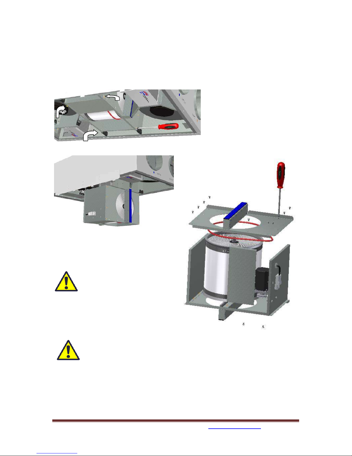
Cleaning the fans.
This must be done by a qualified person.
Be
fore removing fans the main power must be
disconnected by pulling out the main supply
plug from the socket, or fans to be
programmed to position “AV” or “OFF”
Disconnect the 3-pole and 5-pole plugs.
Before you are able to remove the fans you
first have to unscrew two screws for each fan
that holds the fan in correct position.
T
he fans can then be pulled out of the
ventilation unit without the need for any tools.
W
hen the fan is placed back into the unit, then
make sure the screws are tightened so that
there is no danger that they loosen during
operation.
Clean with mild soap and water.
393870-2 Rev 0: 11.07.2018 BBV
We reserve the right to change technical data without notice. http://www.ensy.no Page 6
Maintenance and cleaning of rotary heat exchanger
This must be done by a qualified person.
If the unit is placed high under a ceiling, then it might be an advantage to get help from another
person to hold the rotor exchanger in correct position till all four “safety” screws are loosen.
D
isconnect the 3-poled plug , and then unscrew those four “safety” screws that holding the rotor
exchanger in place.
(Sketch shows AHU-300 HH, but the
princip is the same for AHU-300 HV)
C
an be pulled out of the ventilation
unit without the need for any tools.
R
otor exchanger can easily be removed for
cleaning by unscrewing 12 screws that hold it
together.
Clean parts with mild soap and water.
Do not expose the rotor motor or
connector for moisture.
The exchanger you also can clean
with mild soap and water. Do not use ammoniacontaining detergent, as this will prey on and
discolor aluminum in rotary heat exchanger.
Flushed with hand shower and blow gently clean
with compressed air.
Ensure that all 12 screws are tightened sufficiently so that they do not come loose
during operation.
Preferably use a screwdriver to tight the screws. If use of electrical screwdriver, make
sure that you use low torque to prevent destroying the threads in the sheet metal parts.
To make sure that the drive belt can adjust itself into correct position you must rotate the exchanger
some few turns. Then insert back into the ventilation unit. Be sure that rotor exchanger is properly
inserted in all the guides inside the unit. If not, this can lead to vibration in the system and internal
air leak in the unit. Make sure that all four “safety” screws are tightened so that there is no danger
that they loosen during operation.
393870-2 Rev 0: 11.07.2018 BBV
We reserve the right to change technical data without notice. http://www.ensy.no Page 7
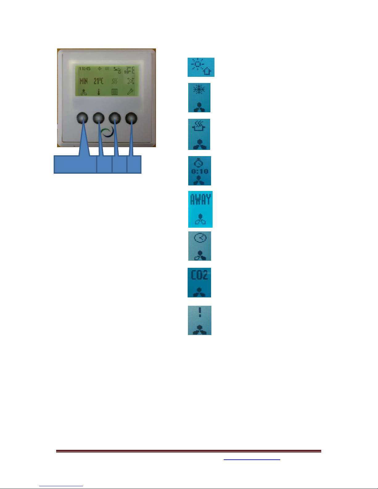
Main menu
1. Control Button indicator for fan.
2
. C
ontrol Button indicator set point.
3
. C
ontrol Button indicator information.
4
. C
ontrol Button indicator settings.
Overview of control panel
The main screen consists of, from top, left:
Time Indication, hour, minute
Ti
mer, Weekly schedule (if programmed)
Reheating coil (if connected)
T
emperature readings, Outdoor / Indoor
S
tatus airflow – fan speed setting
OFF MIN NORM or MAX
Tem
perature set point, 15 - 21 °C
R
eheating coil – (here refers active element)
R
otary exchanger Indicator - (here refers
active rotary wheel)
Indicators in the menu screen:
"
Sun" indicates that the rotor has
stopped, the air handling unit is in the
summer operation mode.
"Snowflake" low temperature
indicates that the air handling unit is
in defrosting mode.
"
Steaming pot" and blinking fan blades
indicates that the kitchen exhaust is
activated.
"
Timer" and the countdown of the fan
symbol indicate that the forced
ventilation is enabled.
From 10 up to 240 minutes
"
Away" indicates when the feature is
enabled, this feature will override
timer.
"Clock over the fan symbol" indicates
that the timer is activated.
Co2 over the fan symbol" indicates
that the carbon sensor is activated.
"Ex
clamation point" indicates that
moisture recorded over the sensor is
higher than the set value.
May also indicate that the motion
sensor is activated if connected on D2
signal output.
Control Button 1.
2.
3.
4.
393870-2 Rev 0: 11.07.2018 BBV
We reserve the right to change technical data without notice. http://www.ensy.no Page 8
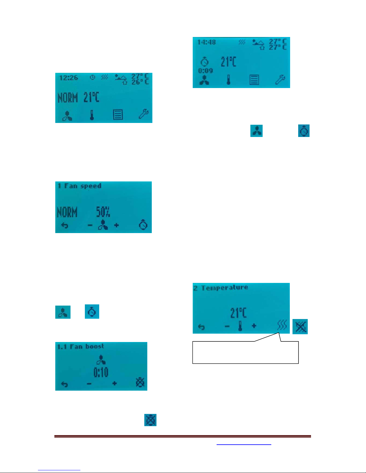
1.Fan speed
Ventilation unit has three options for choice of
airflow.
M
in, Normal and Max.
For programming of values within each step,
see 4.5.1.3 Using the control button 1, and - /
+ buttons can change between the preprogrammed selections.
1
.1 Fan boost
Forced ventilation, fan speed increases to max
speed. (Means to the speed that is set in
menu 4.5.1.3.) The function is for use if high
humidity in bathrooms and laundry room.
Forced ventilation can be activated with
button
then
I
nterval adjustable from 10 - 240 min with +
and -
T
his picture shows 10 min forcing time, but
not activated.
To activate the fan boost use
control button 4.
Y
ou can see that the fan are running with Max
speed and the clock will start countdown.
You can easy deactivate the fan boost again
before the countdown automatically stops it.
First control buttom 1
and then 4.
This feature can also be operated with an
external pulse switch. The switch is placed in
the bathroom or adjacent rooms. Connected
to contact D1 in top of the ventilation unit.
(Look at page 19 or 20 in this manual.)
If this option via D1 is intended for use against
wood stove or fireplace then it is
recommended that Max speed under Fan
control in menu 4.5.1.3. is set to Supply 100%
and adjust Extract to be 80 to 85%. (Look at
page 10 in this manual)
2. Temperature
Choose from pre-programmed temperature
settings set point between 15 - 21 °C. Setting
is changed by operating the switch buttons
below - / + symbols.
Heating element can here be set ON or OFF
by operating the switch button 4 in this
screen, but only if heater is connected.
(To see if heating coil is connected or
disconnected, see 4.5.1.1 Heater)
Indicator for activated heating coil.
Small picture show not activated.
393870-2 Rev 0: 11.07.2018 BBV
We reserve the right to change technical data without notice. http://www.ensy.no Page 9
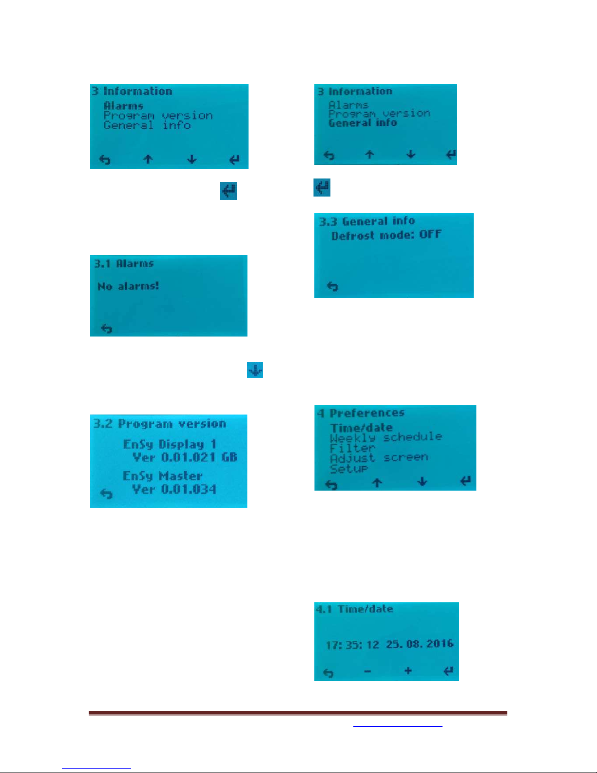
3. Information.
3. I
nformation / 3.1.Alarms
When alarm you can find a source of error
here, as well as info on how the alarm is reset.
(See pages 29 and 30 in this manual)
3.
Information / 3.2 Program version
Information about the software
version. This information must be provided to
service personnel at the failure of the unit.
W
hich display is defined as Display 1 or
Display 2 appears here if the plant has
mounted two displays.
See 4.5.1.10 selection of the displays.
3.
Information / 3.3. General info
H
ere you can see defrost mode that has
been chosen.
(
See 4.5.1.9 if you want to change mode.)
4. Preferences
To navigate within the various sub-menus
when using the control buttons below the up /
down cursor key that displays on the display.
4. P
references / 4.1 Time/date
Setting menu for Time/date. This setting is
important since the information forming the
basis for the weekly schedule function if this is
to be activated. Also for the filter alarm
function it is needed.

393870-2 Rev 0: 11.07.2018 BBV
We reserve the right to change technical data without notice. http://www.ensy.no Page 10
4. Preferences / 4.2 Weekly schedule
Programming of the Weekly schedule, fan
speed and temperature set point. Here it can
be programmed for two periods each day. Ex.
day - night.
E
very day must be programmed individually.
Monday - a period of time, select the start
time. To activate the period, X - over period
number is removed, use the - / + keys.
Use enter to move between the different
fields.
C
hoose airflow (fan speed) Speed dialing MIN when one fan blade on the indicator is
black. NORM = two black fan blades on the
indicator. MAX speed = three black fan blades
on the indicator.
Select the desired supply air temperature you
want during the period. Settings between 15 21°C.
If weekly schedule looks something like
this without any reason then you must
punch in all the data again.
It do not help to update software.
4.P
references / 4.3 Filter
Setting the time interval for filter change,
current choices are 6, 9 or 12 months. Make
your choices by using the cursor keys + / -.
A
larm reset elapsed period by pressing the
menu button 4, under "Filter OK"
4. Preferences / 4.4 Adjust Screen
Adjusting the contrast and color on the
display.
Y
ou can also adjust how long it should be light
in the display after the operation.
4. Preferences / 4.5 Setup
To proceed, use PIN code 1000
P
ress
+ once till it shows 1000 in
display. Then press 4 times on
T
hen press button 3 for OK 4.5.1
Start time
Stop time
Fan speed
Activation of the period. Here not active
 Loading...