

Page 1
Visit www.enstromhelicopter.com for instructions to order an original manual and to register for email notification of updates.
UNCONTROLLED COPY WHEN DOWNLOADED OR PRINTED
ENSTROM TH-28/480 SERIES MAINTENANCE MANUAL
SUPPLEMENT 1
ENSTROM 480/480B AIR CONDITIONING SYSTEM
P/N 4220176-( )
The Airworthiness Limitations Section is FAA approved and specifies
inspections and other maintenance required under 14 CFR §§ 43.16 and
91.403 of the Federal Aviation Regulations unless an alternative program
has been FAA approved.
This manual supplement supersedes all previous editions of the TH-28/480 Maintenance
Manual Supplement 1 originally dated November 26, 1996.
Copyright 2011, 2017 by
The Enstrom Helicopter Corporation
2209 22
Menominee, Michigan 49858-3515
http://enstromhelicopter.com/
Telephone: 906-863-1200
Fax: 906-863-6821
nd
Street
Rev. 8
i May 1/17
Page 2

ENSTROM TH-28/480 SERIES MAINTENANCE MANUAL SUPPLEMENT 1
Visit www.enstromhelicopter.com for instructions to order an original manual and to register for email notification of updates.
UNCONTROLLED COPY WHEN DOWNLOADED OR PRINTED
INTENTIONALLY LEFT BLANK
Rev. 8
ii May 1/17
Page 3

ENSTROM TH-28/480 SERIES MAINTENANCE MANUAL SUPPLEMENT 1
Visit www.enstromhelicopter.com for instructions to order an original manual and to register for email notification of updates.
UNCONTROLLED COPY WHEN DOWNLOADED OR PRINTED
RECOMMENDED CHANGE REPORT
This maintenance manual is prepared and distributed by The Enstrom Helicopter Corporation
and is intended for use by personnel responsible for maintaining Enstrom TH-28, 480, and 480B
helicopters. This manual is periodically revised. If, in the opinion of the user, any information has
been omitted or requires clarification, please direct your comments to Enstrom via this form
(duplicate) or other similar form. Send the recommended changes to:
The Enstrom Helicopter Corporation
2209 22
nd
Street
Menominee, MI 49858-3515
ATTN: Technical Publications
Manual Identification: Enstrom TH-28/480 Series Maintenance Manual Supplement 1
Manual Date: February 9, 2001
Revision Number and Date:
Aircraft Model:
Recommended Change:
Rev. 8
iii May 1/17
Page 4

ENSTROM TH-28/480 SERIES MAINTENANCE MANUAL SUPPLEMENT 1
Visit www.enstromhelicopter.com for instructions to order an original manual and to register for email notification of updates.
UNCONTROLLED COPY WHEN DOWNLOADED OR PRINTED
INTENTIONALLY LEFT BLANK
Rev. 8
iv May 1/17
Page 5

ENSTROM TH-28/480 SERIES MAINTENANCE MANUAL SUPPLEMENT 1
Visit www.enstromhelicopter.com for instructions to order an original manual and to register for email notification of updates.
UNCONTROLLED COPY WHEN DOWNLOADED OR PRINTED
TABLE OF CONTENTS
Paragraph Description Page
Cover Page ..................................................................................................... i
Recommended Change Report ...................................................................... iii
Table of Contents ........................................................................................... v
Effective Page List ......................................................................................... vii
Section 1 Introduction
1-1. Aircraft Effectivity ......................................................................................... 1-1
1-2. Supplemental Changes and Revisions ....................................................... 1-1
1-3. Service Document Publications ................................................................... 1-1
1-4. Application of Warnings, Cautions, and Notes ............................................ 1-2
Section 2 General Information
2-1. System Description ..................................................................................... 2-1
2-2. Safety Precautions ...................................................................................... 2-2
2-3. Equipment and Consumables ..................................................................... 2-3
2-4. Suggested Spares List ................................................................................ 2-4
Section 3 Airworthiness Limitations
3-1. Airworthiness Limitations ............................................................................. 3-1
Section 4 Lubrication, Servicing, Troubleshooting, and Periodic Inspections
4-1. Lubrication ................................................................................................... 4-1
4-2. Servicing ...................................................................................................... 4-1
4-3 Troubleshooting ........................................................................................... 4-3
4-4 Periodic Inspections .................................................................................... 4-5
4-5 Periodic Inspection Checklist ...................................................................... 4-5
Section 5 System Maintenance
5-1. Belt Replacement and Adjustment, Pulley Alignment ................................. 5-1
5-2. Refrigerant Fitting Installation ...................................................................... 5-5
5-3. Leak Check ................................................................................................. 5-6
Plumbing Schematic Diagrams
A-1. Two Evaporator System ............................................................................. A-1
A-2. Three Evaporator System .......................................................................... A-2
A-3. Two Evaporator, Litter Compatible System ................................................ A-3
Electrical Schematic Diagrams
B-1. Two Evaporator System ............................................................................. B-1
B-2. Three Evaporator System .......................................................................... B-2
B-3. Transient Suppression Circuitry ................................................................. B-3
B-4. Two Evaporator, Litter Compatible System ................................................ B-4
Rev. 8
v May 1/17
Page 6

ENSTROM TH-28/480 SERIES MAINTENANCE MANUAL SUPPLEMENT 1
Visit www.enstromhelicopter.com for instructions to order an original manual and to register for email notification of updates.
UNCONTROLLED COPY WHEN DOWNLOADED OR PRINTED
INTENTIONALLY LEFT BLANK
Rev. 8
vi May 1/17
Page 7

ENSTROM TH-28/480 SERIES MAINTENANCE MANUAL SUPPLEMENT 1
Visit www.enstromhelicopter.com for instructions to order an original manual and to register for email notification of updates.
UNCONTROLLED COPY WHEN DOWNLOADED OR PRINTED
EFFECTIVE PAGE LIST
Page Date Page Date
i May 1/17
ii May 1/17
iii May 1/17
iv May 1/17
v May 1/17
vi May 1/17
vii May 1/17
viii May 1/17
1-1 May 1/17
1-2 May 1/17
2-1 Dec 3/10
2-2 Dec 3/10
2-3 May 1/17
2-4 May 1/17
2-5 May 1/17
2-6 May 1/17
2-7 May 1/17
2-8 May 1/17
2-9 May 1/17
2-10 May 1/17
3-1 May 1/17
3-2 May 1/17
4-1 Feb 20/08
4-2 Feb 20/08
4-3 Feb 9/01
4-4 Feb 9/01
4-5 May 1/17
4-6 May 1/17
5-1 May 1/17
5-2 May 1/17
5-3 May 1/17
5-4 May 1/17
5-5 Mar 17/09
5-6 Mar 17/09
A-1 Jun 14/11
A-2 Jun 14/11
A-3 Jun 14/11
A-4 Sep 12/08
B-1 Dec 3/10
B-2 Dec 3/10
B-3 Dec 3/10
B-4 Dec 3/10
Rev. 8
vii May 1/17
Page 8

ENSTROM TH-28/480 SERIES MAINTENANCE MANUAL SUPPLEMENT 1
Visit www.enstromhelicopter.com for instructions to order an original manual and to register for email notification of updates.
UNCONTROLLED COPY WHEN DOWNLOADED OR PRINTED
INTENTIONALLY LEFT BLANK
Rev. 8
viii May 1/17
Page 9

ENSTROM TH-28/480 SERIES MAINTENANCE MANUAL SUPPLEMENT 1
Visit www.enstromhelicopter.com for instructions to order an original manual and to register for email notification of updates.
UNCONTROLLED COPY WHEN DOWNLOADED OR PRINTED
SECTION 1
INTRODUCTION
1-1. Aircraft Effectivity
A. The data presented in this TH-28/480 Series Maintenance Manual Supplement is
applicable to all Enstrom 480 and 480B model helicopters equipped with the optional air
conditioning system, Part Numbers 4222176-1, 4220176-2, 4220176-3, 4220176-5, 4220176-6,
or 4220176-7.
1-2. Supplemental Changes and Revisions
A. Subsequent to the publication of the initial issue of this supplement, changes in the air
conditioning equipment, support concepts and procedures, as well as information developed by
experience may affect the contents of this supplement. To ensure that coverage in the
supplement continues to reflect such changes, revised information is released by one of the
following methods:
1. Revision - A revision alters portions of the manual by replacement, addition, and/or
removal of pages.
2. Reissue - A reissue of this supplement will occur when the amount of changes
warrants complete reissue.
1-3. Service Document Publications
1. Service Directive Bulletins - Used to direct the owner/operator and/or maintenance
personnel to make mandatory changes, improvements, or inspections to the aircraft
applicable to the entire or a segment of the aircraft fleet that are typically
safety/airworthiness related. The
will be incorporated in the
At the time of incorporation, the Service
maintenance manual supplement, and accomplishment or signDirective Bulletin in the maintenance records book is no longer required.
entry should be made in the maintenance records to indicate that the Service
Bulletin is superseded by the maintenance manual supplement.
2. Service Information Letters - Used to transmit information, recommendations, and
general
personnel applicable to the entire or a segment of the aircraft fleet. The
provided in the Service Information Letters will be incorporated into the
manual supplement as needed at a later date.
service instructions to the aircraft owner/operator and/or maintenance
information provided in the Service Directive Bulletins
maintenance manual supplement as needed at a later date.
Directive Bulletin is superseded by the
off of the Service
A detailed
Directive
information
maintenance
3. Service Instructions – Used to provide the owner/operator and/or maintenance
personnel with information that is applicable to specific aircraft and does not meet the
criteria of a Service Information Letter or Service Directive Bulletin. Service Instructions
will not be distributed to the entire fleet.
Rev. 8
1-1 May 1/17
Page 10

ENSTROM TH-28/480 SERIES MAINTENANCE MANUAL SUPPLEMENT 1
Visit www.enstromhelicopter.com for instructions to order an original manual and to register for email notification of updates.
UNCONTROLLED COPY WHEN DOWNLOADED OR PRINTED
Service Information Letters and Service Directive Bulletins incorporated into the
maintenance
the Service Directive Bulletin Index
website: www.enstromhelicopter.com (follow
Publications section of the Technical Support page). Each index numerically lists all
Service Information Letters and Service Directive Bulletins,
those which have been incorporated into the maintenance manual supplement.
Service Information Letters and Service Directive Bulletins are also located under the
Tech
Publications section of the website.
Enstrom distributes maintenance manual supplement reissues and revisions in
hardcopy form via mail to
Notice of recently released Service
provided via a postcard mailing. Registration to receive publication mailings can be
coordinated through Enstrom Product
1-4. Application of Warnings, Cautions, and Notes
A. Throughout this supplement, it is necessary to highlight or emphasize important points
to avoid injury to personnel, damage to equipment, or unnecessary confusion while performing
maintenance procedures. The terms “WARNING”, “CAUTION”, and “NOTE” are used to draw
attention to instructions or information deserving special consideration.
manual supplement are logged in the Service Information Letter Index or
(as appropriate) located on the Enstrom Helicopter
the applicable link under the Tech
respectively, and identifies
All
owners and operators who are registered with Enstrom.
Information Letters and Service Directive Bulletins is
Support.
B.
C.
D.
WARNING
Calls attention to use of materials, processes, methods,
procedures, or limits that must be followed to avoid injury to
personnel.
CAUTION
Calls attention to methods and procedures that must be followed
to avoid damage to equipment.
NOTE
Calls attention to information essential to highlight for clarification
of procedures or to make a task easier.
Rev. 8
1-2 May 1/17
Page 11

ENSTROM TH-28/480 SERIES MAINTENANCE MANUAL SUPPLEMENT 1
Visit www.enstromhelicopter.com for instructions to order an original manual and to register for email notification of updates.
UNCONTROLLED COPY WHEN DOWNLOADED OR PRINTED
SECTION 2
GENERAL INFORMATION
2-1. System Description
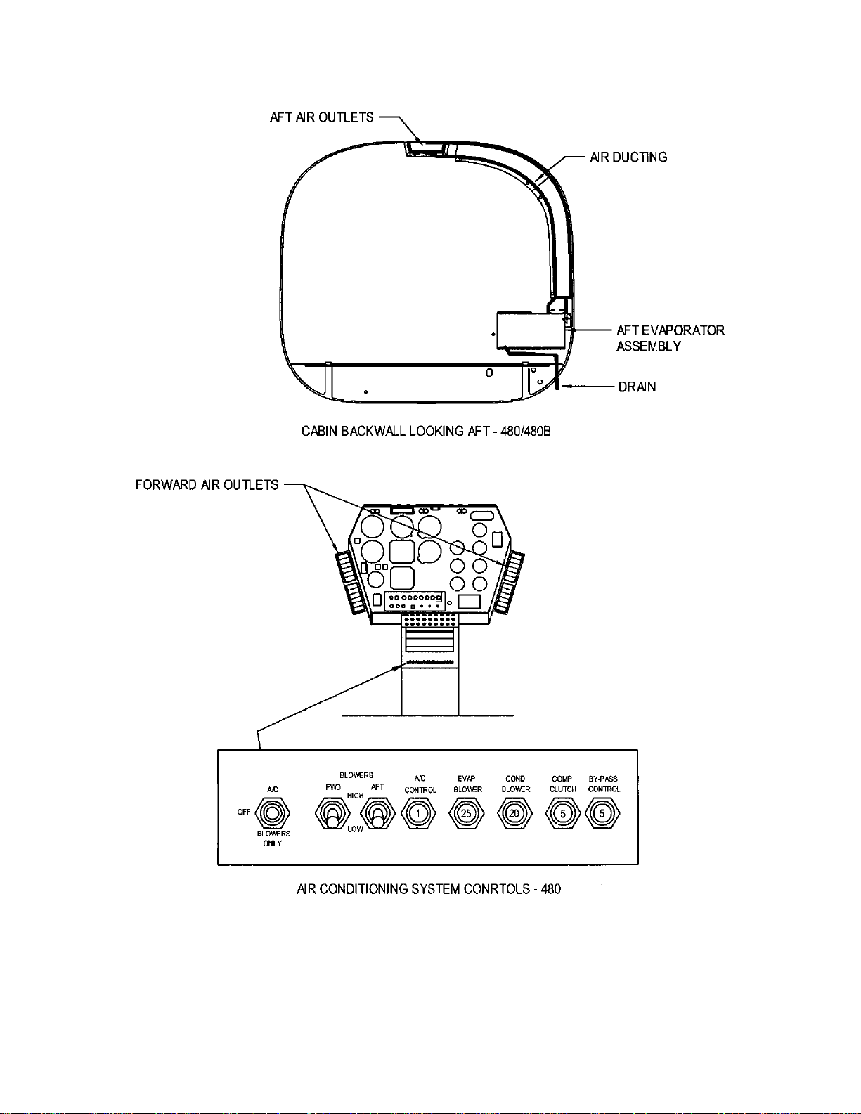
A. The air conditioning system, Part Number 4220176, is a vapor cycle type air
conditioner consisting of a compressor, condenser, receiver/drier bottle, by-pass valve, two
(4220176-1, -3, -5 or -7) or three (4220176-2 or -6) evaporator assemblies, plumbing, and
electrical control equipment. The refrigerant used in this system is HFC R134a. Refer to Figure
2-1 for the general arrangement of the air conditioning system.
NOTE
Part numbers 4220176-1, -2, or -3 are applicable to aircraft with a
110 amp system (S/N 5133 and earlier). Part numbers 4220176-5,
-6, or -7 are applicable to aircraft with a 150 amp system (S/N
5134 and subsequent).
B. The compressor, located on the left side of the lower pulley assembly, is a five cylinder,
reed valve, wobble plate type air conditioner compressor. It is belt driven off the lower pulley
assembly and is engaged electrically by a magnetic clutch. It is lubricated with oil carried by the
refrigerant.
C. The condenser, located in the tail cone aft of the baggage box, is a tube-fin design with
an axial flow cooling fan mounted directly above the condenser. The cooling fan draws fresh air
supplied by two air scoops mounted on opposite sides of the tailcone. The condenser air exit is
located at the bottom of the tailcone.
D. The receiver/drier bottle, located in the left side of the tailcone next to the condenser, is
the system reservoir. The receiver/drier bottle contains a desiccant filter (silica gel) which serves
to absorb moisture from the system.
E. The by-pass valve, located in the right side of the tailcone next to the condenser, is
used to prevent evaporator heat exchanger freeze-up by controlling the minimum evaporator
pressure (temperature). A thermally controlled switch, located in the left side forward evaporator
assembly, controls the by-pass valve.
F. Two evaporator assemblies (4220176-1, -2, -5 and -6) are located in the nose of the
helicopter. The evaporator assemblies are equipped with a centrifugal blower and a tube-fin
heat exchanger. Cooled air is discharged via four adjustable vents, two located on each side of
the instrument console. An optional third evaporator assembly (4220176-2 or -6) can be
mounted behind the pilot's seat to provide additional cooling for occupants of the aft bench seat
in the 480/480B. Cooling air from the third evaporator is ducted to vents located above the
bench seat occupants. An optional single evaporator assembly (4220176-3 or -7) with a
modified mount assembly allows compatibility of a litter installation in the nose of the helicopter.
The litter compatible air conditioning option also consists of a second evaporator assembly
(4220176-3 or -7) mounted behind the pilot’s seat to provide additional cooling.
Rev. 5
2-1 Dec 3/10
Page 12

ENSTROM TH-28/480 SERIES MAINTENANCE MANUAL SUPPLEMENT 1
Visit www.enstromhelicopter.com for instructions to order an original manual and to register for email notification of updates.
UNCONTROLLED COPY WHEN DOWNLOADED OR PRINTED
G. The plumbing used in this air conditioning system consists of aluminum hard lines,
medium pressure rubber flex lines, "B" nut pressure fittings, unions, and tees. Servicing ports
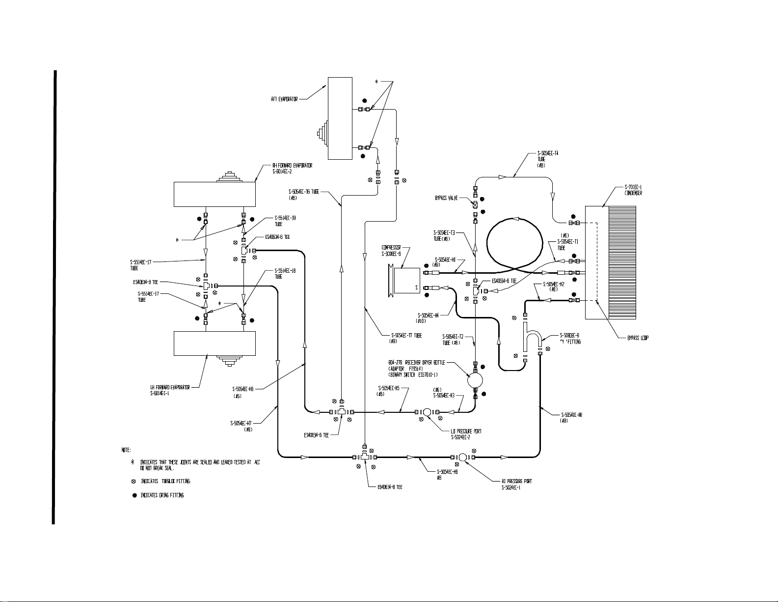
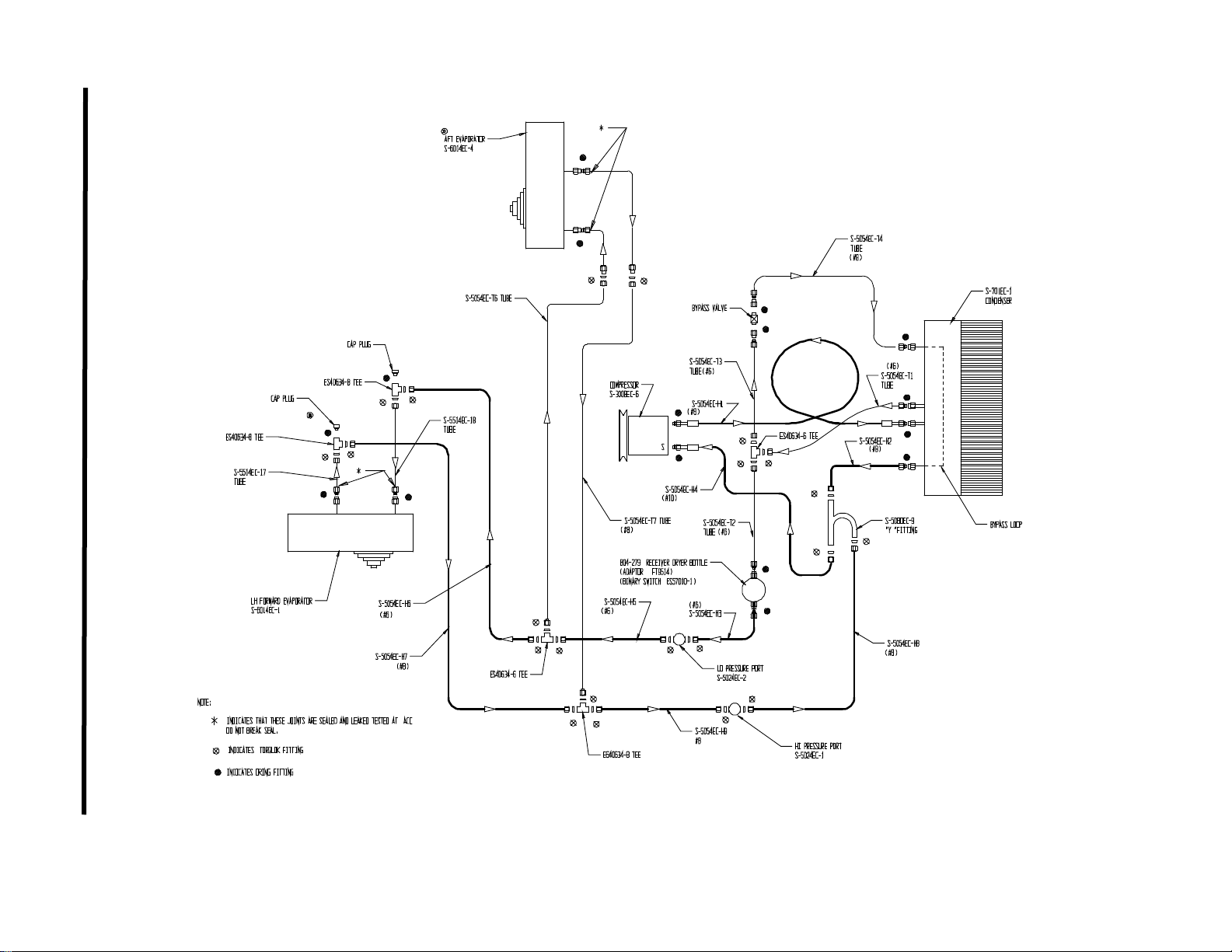
are located on the left side of the aircraft above the aft crosstube. Plumbing schematic diagrams
(A-1, A-2, and A-3) are located in the back of this supplement.
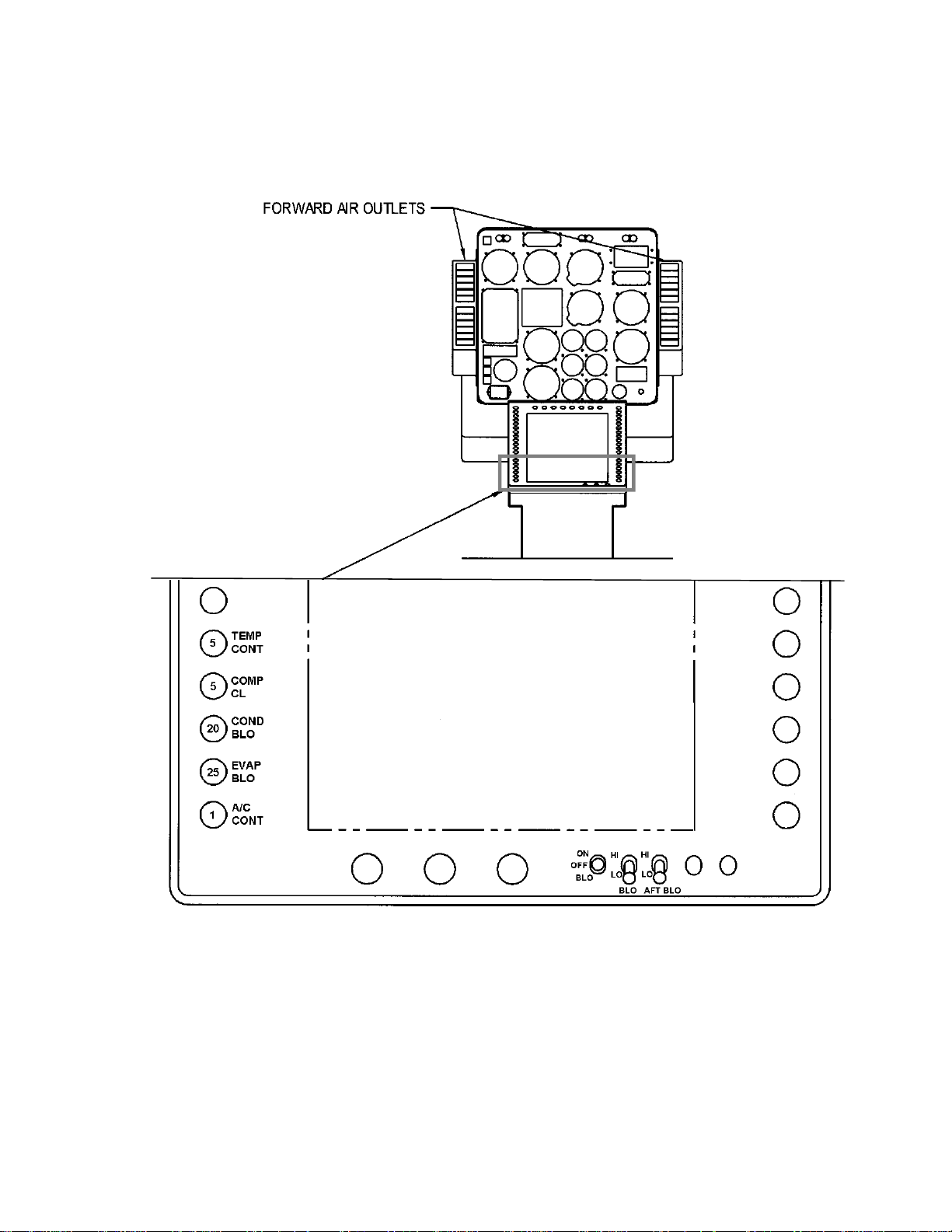
H. The air conditioner system is controlled by switches located in the center pedestal. The
pilot can turn the system on, off, or select the evaporator blowers only. The pilot can also select
high or low blower speeds. If the optional third evaporator assembly is installed, a separate
switch for controlling blower speed is installed. Actual location of the air conditioning system
switches in the 480B may change because of customer specified avionics installations.
The electrical system has a binary HI/LOW pressure switch, located on the receiver/drier bottle,
wired in series with the compressor clutch. This switch is intended to protect the compressor in
case of system over-pressure or loss of refrigerant. The switch operating pressures are:
Low pressure function - opens at 30 psi (207 kPa)
closes at 50 psi (345 kPa)
Hi pressure function - opens at 335 psi (2310 kPa)
closes at 280 psi (1931 kPa)
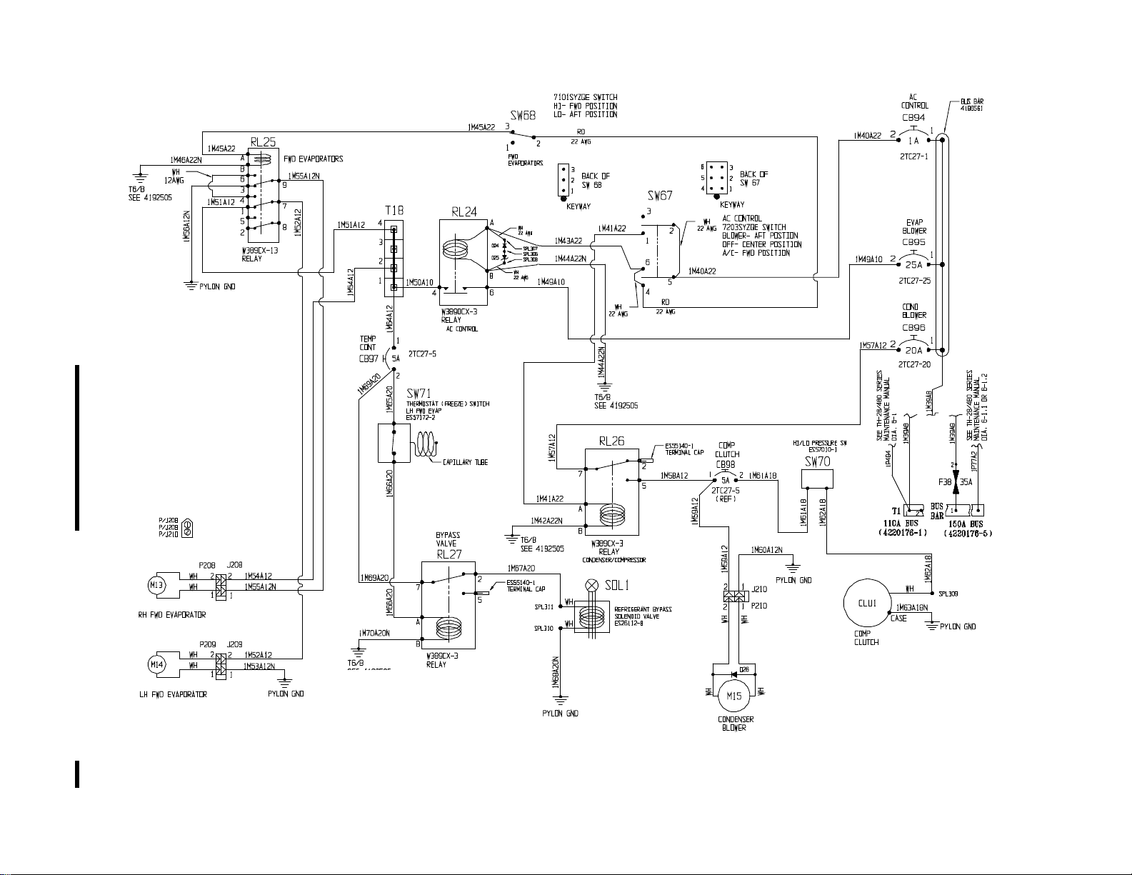
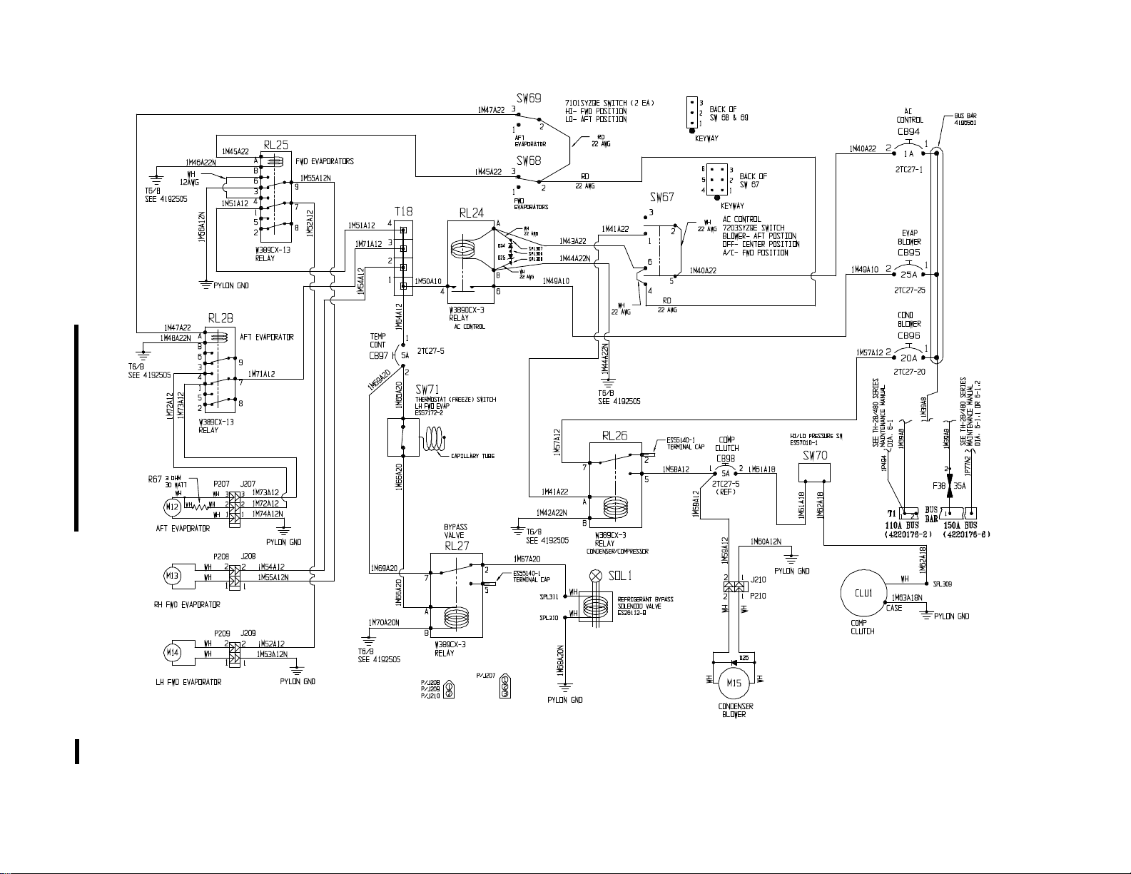
Electrical schematic diagrams (B-1, B-2, B-3, and B-4) are located in the back of this
supplement.
2-2. Safety Precautions
A. The refrigerant used in the air conditioning system is HFC R134a. This refrigerant is
non-explosive, non-flammable, non-corrosive, has practically no odor, and is heavier than air.
Although R134a is classified as a safe refrigerant, certain precautions must be observed to
protect parts involved and the person working on the unit.
B. Liquid R134a at normal atmospheric pressure and temperature evaporates so quickly
that it tends to freeze anything that it contacts. Care must be taken to prevent any liquid
refrigerant from coming in contact with the skin, especially the eyes. R134a is readily absorbed
by most types of oil. Therefore, it is recommended a bottle of clean mineral oil and weak
solution of boric acid be kept nearby when servicing the refrigerant system.
WARNING
This air conditioning system should only be serviced by
qualified personnel.
WARNING
Always wear safety goggles when servicing any part of the
refrigeration system. Should any liquid refrigerant get into
the eyes, use a few drops of mineral oil to wash them out,
then use a weak solution of boric acid to wash the eyes, and
seek aid from a doctor immediately even though the irritation
has ceased.
Rev. 5
2-2 Dec 3/10
Page 13

ENSTROM TH-28/480 SERIES MAINTENANCE MANUAL SUPPLEMENT 1
Visit www.enstromhelicopter.com for instructions to order an original manual and to register for email notification of updates.
UNCONTROLLED COPY WHEN DOWNLOADED OR PRINTED
C. It is important to keep the system tightly sealed because the refrigerant system is
always under pressure. Heat applied to any part of the refrigerant system would cause the
pressure to build up excessively.
WARNING
To avoid explosion, never weld, use a flame-type leak
detector, blow torch, solder, steam clean, bake an aircraft
finish, or use excess amounts of heat on or in the immediate
area of any part of the air conditioning system or refrigerant
supply tank while they are closed to the atmosphere.
2-3. Equipment and Consumables
A. The proper equipment for maintaining and servicing the air conditioning system is
required to keep the air conditioning system operating at peak efficiency. The following listed
equipment is recommended for servicing the air conditioning system:
1) Recovery/Recycling/Recharging Station
Suggested Model: Robinair Model 34700 or equivalent
Montpelier, Ohio 43543
(800) 822-5561
2) HFC R134a Refrigerant Electronic Leak Detector
Suggested Model: Signstek Portable AC Refrigerant Halogen Gas Leakage
Detector Tester with High Sensitivity
or equivalent
B. The following consumable items are required for properly maintaining and servicing the
air conditioning system:
1) Refrigerant: DuPont HFC R-134a
CAUTION
Do not use PAG (polyalkylene glycol) lubrication oil in this air
conditioning system. Only use polyester based lubrication oil.
NOTE
All polyester based lubricating oils may not be compatible with
each other when mixed. Follow the oil manufacturer's instructions
concerning mixing of oils.
Rev. 8
2-3 May 1/17
Page 14

ENSTROM TH-28/480 SERIES MAINTENANCE MANUAL SUPPLEMENT 1
Visit www.enstromhelicopter.com for instructions to order an original manual and to register for email notification of updates.
UNCONTROLLED COPY WHEN DOWNLOADED OR PRINTED
NOTE
Refer to the "Log Record Sheets" provided with the aircraft and/or
the maintenance records for the aircraft to determine the
brand/type of lubricating oil used to service the air conditioning
system.
2) Lubricating Oil: Texaco Capella HFC
NOTE
The green o-rings are used on the "Insert O-ring Fitting" type were
the o-ring is installed on the male end of the fitting connection (line
side with the "B" nut). The black o-rings are used on the "Face
Seal O-ring Fitting" type were the o-ring is installed in the female
side of the fitting connection.
3) O-rings: AIR 440-840 (Green) #6 size fitting
AIR 440-841 (Green) #8 size fitting
AIR 440-842 (Green) #10 size fitting
2-012-N1173 (Black) #6 size fitting
2-014-N1173 (Black) #8 size fitting
2-4. Suggested Spares List
A. The following spares list is for remote location operators or fleet aircraft equipped with
the air conditioning system.
Table 2-1. Suggested Spares List
Item
Condenser Blower S-7050EC-5
Compressor S-3008EC-6
Compressor Drive Belt (Gates) 7295
Receiver/Drier Bottle 804-279
Binary HI/LO Pressure Switch ES57008-2
Part Number
Rev. 8
2-4 May 1/17
Page 15

ENSTROM TH-28/480 SERIES MAINTENANCE MANUAL SUPPLEMENT 1
Visit www.enstromhelicopter.com for instructions to order an original manual and to register for email notification of updates.
UNCONTROLLED COPY WHEN DOWNLOADED OR PRINTED
Figure 2-1. Air Conditioning System – General Arrangement
Rev. 8
2-5 May 1/17
Page 16

ENSTROM TH-28/480 SERIES MAINTENANCE MANUAL SUPPLEMENT 1
Visit www.enstromhelicopter.com for instructions to order an original manual and to register for email notification of updates.
UNCONTROLLED COPY WHEN DOWNLOADED OR PRINTED
Fig Part Number Component Quantity
2-1
4220176-1
4220176-2
4220176-3
4220176-5
4220176-6
4220176-7
S-6014EC-1 . Forward Evaporator, LH 1
S-6014EC-2 . Forward Evaporator, RH 1 A,B,D,E
S-6014EC-3 . Aft Evaporator 1 B,E
S-6014EC-4 . Aft Evaporator 1 C,F
E480-300-10 . Compressor Assembly 1
*∆ S-3008EC-6 . . Compressor 1
* 7295 . . Compressor Drive Belt 1
ES73187-1 . Condenser and Fan Assembly 1
* S-7050EC-5 . . Condenser Blower Unit 1
AN525-832R6 . . . Screw (Bracket Attachment) 2
AN960-8L . . . Washer 2
AN364-832 . . . Nut 2
AN3H6A . . . Bolt (Fan Shroud Attachment) 4
AN960-10L . . . Washer 8
4220111-15 . . . Spacer 4
MS20995C20 . . . Safety Wire A/R
* 804-297 . Dryer/Receiver Bottle 1
* ES57008-2 . . Binary HI/LO Pressure Switch 1
ES26112-8 . Bypass Valve 1
ES26112-2 . . Bypass Bottle 1
AN526-832R6 . . . Screw 2
AN935-8 . . . Lockwasher 2
AN960-8L . . . Washer 2
‡ Effective for all 4220176 configurations if blank.
* Refer to Table 2-1 – Suggested Spares
∆ Refer to Figure 2-2
Air Conditioning System Installation
(Two Forward Evaporators)
Air Conditioning System Installation
(Two Forward Evaporators, One Aft Evaporator)
Air Conditioning System Installation
(One Forward Evaporator, One Aft Evaporator)
Air Conditioning System Installation
(Two Forward Evaporators)
(150-Amp System)
Air Conditioning System Installation
(Two Forward Evaporators, One Aft Evaporator)
(150-Amp System)
Air Conditioning System Installation
(One Forward Evaporator, One Aft Evaporator)
(150-Amp System)
REF A
REF B
REF C
REF D
REF E
REF F
EFF
Code‡
Rev. 8
2-6 May 1/17
Page 17
ENSTROM TH-28/480 SERIES MAINTENANCE MANUAL SUPPLEMENT 1
Visit www.enstromhelicopter.com for instructions to order an original manual and to register for email notification of updates.
UNCONTROLLED COPY WHEN DOWNLOADED OR PRINTED
Sheet 2 of 3
Figure 2-1. Air Conditioning System – General Arrangement
Rev. 8
2-7 May 1/17
Page 18
ENSTROM TH-28/480 SERIES MAINTENANCE MANUAL SUPPLEMENT 1
Visit www.enstromhelicopter.com for instructions to order an original manual and to register for email notification of updates.
UNCONTROLLED COPY WHEN DOWNLOADED OR PRINTED
Figure 2-1. Air Conditioning System – General Arrangement
Sheet 3 of 3
Rev. 8
2-8 May 1/17
Page 19
ENSTROM TH-28/480 SERIES MAINTENANCE MANUAL SUPPLEMENT 1
Visit www.enstromhelicopter.com for instructions to order an original manual and to register for email notification of updates.
UNCONTROLLED COPY WHEN DOWNLOADED OR PRINTED
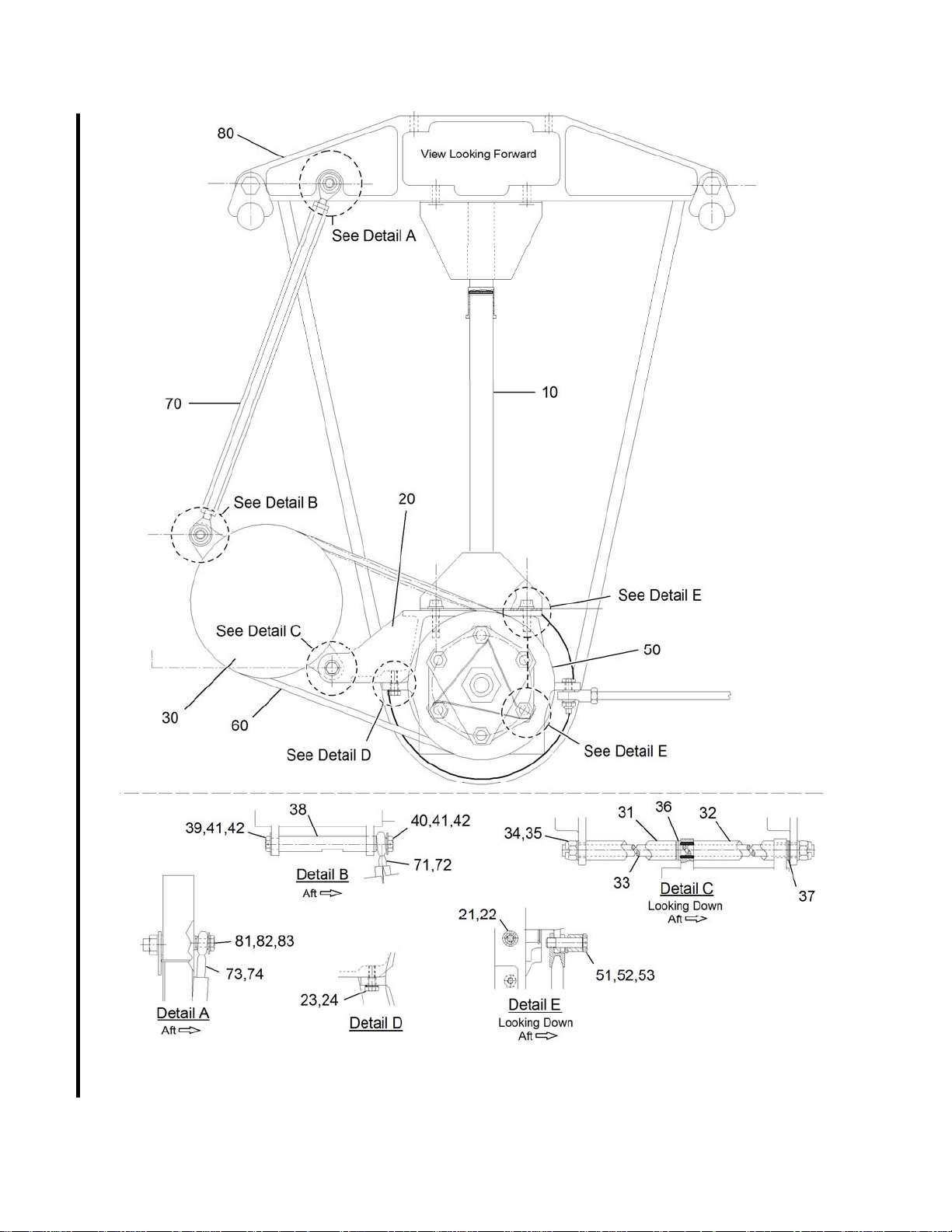
Figure 2-2. Compressor Installation
Rev. 8
2-9 May 1/17
Page 20

ENSTROM TH-28/480 SERIES MAINTENANCE MANUAL SUPPLEMENT 1
Visit www.enstromhelicopter.com for instructions to order an original manual and to register for email notification of updates.
UNCONTROLLED COPY WHEN DOWNLOADED OR PRINTED
Fig
Item
2-2
10 4130531-3 H-Strut Weldment REF
20 4220175-1 . Bracket 2
21 NAS144DH-12 . . Bolt 4
22 MS20002C4 . . Washer 4
23 AN3-5 . . Bolt 2
24 AN960-10L . . Washer 2
30 S-3008EC-6 . Compressor REF
31 4220175-23 . . Spacer 1
32 4220175-21 . . Spacer 1
33 4220175-17 . . Threaded Rod 1
34 F12NE-4753-064 . . Slotted Nut 2
35 AN381-4-12 . . Cotter Pin 2
36 AN960-616 . . Washer 2
37 AN960616L . . Washer (shim) A/R
38 4220184-11 . . Shaft 1
39 AN4H3A . . Bolt 1
40 AN4H10A . . Bolt 1
41 ¼ ID . . Harper Washer 1
42 MS20995C20 . . Safety Wire A/R
50 4220175-11 . Pulley 1
51 4220184-17 . . Bolt 3
52 4220184-15 . . Spacer 3
53 MS20995C32 . . Safety Wire A/R
60* 7295 . . Belt 1
70 4220175-15 . Tie Rod 1
71 HMLVV-4M . . Rod End 1
72 AN316-4L . . Nut 1
73 HMVV-4M . . Rod End 1
74 AN316-4R . . Nut 1
80 4130511-3 . Truss Assembly REF
81 AN4-7 . . Bolt 1
82 AN960-416L . . Washer (truss side) 2
83 ¼ ID . . Harper Washer (under head) 1
- Item not illustrated
* Refer to Table 2-1 – Suggested Spares
Part Number Component Quantity
- M81934/1-C014 . . Bushing 2
Rev. 8
2-10 May 1/17
Page 21

ENSTROM TH-28/480 SERIES MAINTENANCE MANUAL SUPPLEMENT 1
Visit www.enstromhelicopter.com for instructions to order an original manual and to register for email notification of updates.
UNCONTROLLED COPY WHEN DOWNLOADED OR PRINTED
SECTION 3
AIRWORTHINESS LIMITATIONS
3-1. Airworthiness Limitations
A. The Airworthiness Limitations Section is FAA approved and specifies inspections and
other maintenance required under 14 CFR §§ 43.16 and 91.403 of the Federal Aviation
Regulations unless an alternative program has been FAA approved.
B. All components of the air conditioning system are “on condition”.
Rev. 8
3-1 May 1/17
Page 22

ENSTROM TH-28/480 SERIES MAINTENANCE MANUAL SUPPLEMENT 1
Visit www.enstromhelicopter.com for instructions to order an original manual and to register for email notification of updates.
UNCONTROLLED COPY WHEN DOWNLOADED OR PRINTED
INTENTIONALLY LEFT BLANK
Rev. 8
3-2 May 1/17
Page 23

ENSTROM TH-28/480 SERIES MAINTENANCE MANUAL SUPPLEMENT 1
Visit www.enstromhelicopter.com for instructions to order an original manual and to register for email notification of updates.
UNCONTROLLED COPY WHEN DOWNLOADED OR PRINTED
SECTION 4
LUBRICATION, SERVICING, TROUBLESHOOTING, AND PERIODIC INSPECTIONS
4-1. Lubrication
WARNING
This air conditioning system should only be serviced by
qualified personnel.
A. The total system oil charge is 7.4 ± .5 oz. (219 ± 15 ml). The compressor is charged at
the factory with 3.4 oz. (100.6 ml) of oil. An additional 4 oz. (118.4 ml) of oil should be added to
the discharge line prior to system charging. The oil charge is continuously circulated by the
refrigerant. Normally, it is not necessary to add additional oil unless a large amount of oil is lost
due to sudden rupture of the line.
NOTE
Care should be taken to avoid spilling any of the compressor oil
charge during installation. If this should occur, drain the oil and
recharge the compressor to 3.4 oz. (100.6 ml).
Refer to the "Log Record Sheets" provided with the aircraft and/or
the maintenance records for the aircraft to determine the
brand/type of lubricating oil used to service the air conditioning
system.
4-2. Servicing
This air conditioning system should only be serviced by
qualified personnel.
Always wear safety goggles when servicing any part of the
refrigeration system. Should any liquid refrigerant get into
the eyes, use a few drops of mineral oil to wash them out,
then use a weak solution of boric acid to wash the eyes, and
seek aid from a doctor immediately even though the irritation
has ceased.
NOTE
WARNING
WARNING
A. Connect the service manifold and vacuum pump to the service ports located on the left
side of the helicopter near the aft crosstube.
Rev. 2
4-1 Feb 20/08
Page 24

ENSTROM TH-28/480 SERIES MAINTENANCE MANUAL SUPPLEMENT 1
Visit www.enstromhelicopter.com for instructions to order an original manual and to register for email notification of updates.
UNCONTROLLED COPY WHEN DOWNLOADED OR PRINTED
B. Turn on the vacuum pump and open both valves on the service manifold to evacuate
the system.
NOTE
When the pressure drops to 29.40 in Hg. (-1 bar) moisture
vaporizes and is drawn out of the system. Complete removal of
moisture is important to prevent blockage of the expansion valves
by ice.
C. After the system has been evacuated, close both service manifold valves and then turn
off the vacuum pump. If the system will not hold a vacuum, the system has a fitting leak. All
fittings should be checked to insure that they are tight. It might be necessary to charge the
system with 60-80 psi (414-552 kPa) of refrigerant and conduct a leak check survey with an
electronic leak detector and/or soap solution.
NOTE
The system must be leak free to ensure trouble free operation of
the air conditioning system.
D. After the system is proven "leak free", evacuate the system for at least 30 minutes.
E. Charge the system with HFC R-134a refrigerant. The two evaporator system (-1) uses
approximately 2.4 lbs (1.1 kg) of refrigerant. The three evaporator system (-2) uses
approximately 2.6 lbs (1.2 kg) of refrigerant.
F. Test run the air conditioning system after charging. Adjust the system charge if
required to achieve the pressures shown in Table 4-1.
Table 4-1. System Pressures
Ambient Temp
°F (°C)
55 (12.8) 95-115 (655-793) 30-40 (207-276)
60 (15.6) 105-125 (724-862) 30-40 (207-276)
65 (18.3) 115-135 (793-931) 30-40 (207-276)
70 (21.1) 130-150 (896-1034) 30-40 (207-276)
75 (23.9) 150-170 (1034-1172) 30-40 (207-276)
80 (26.7) 165-185 (1138-1276) 30-40 (207-276)
85 (29.4) 175-195 (1207-1345) 30-40 (207-276)
90 (32.2) 185-205 (1276-1413) 30-40 (207-276)
95 (35.0) 210-225 (1448-1551) 30-40 (207-276)
100 (37.8) 220-240 (1517-1655) 30-40 (207-276)
105 (40.6) 240-260 (1655-1793) 30-40 (207-276)
High Pressure
Gauge Reading PSI (kPa)
Suction (Low) Pressure
Gauge Reading PSI (kPa)
Rev. 2
4-2 Feb 20/08
Page 25

ENSTROM TH-28/480 SERIES MAINTENANCE MANUAL SUPPLEMENT 1
Visit www.enstromhelicopter.com for instructions to order an original manual and to register for email notification of updates.
UNCONTROLLED COPY WHEN DOWNLOADED OR PRINTED
4-3. Troubleshooting
A. Prior to troubleshooting a defective system, conduct a visual inspection for general
condition. Inspect the condenser fins for damage, comb out bent fins. Check the system circuit
breakers located in the center pedestal.
B. The following step by step procedure lists the easiest checks and most likely problem
sources for a system that is not working properly.
1) With the engine off, turn the system control switch to "BLOWERS ONLY" and
make sure all the evaporator blowers work in "HIGH" and "LOW" modes. Pull the "EVAP
BLOWER" circuit breaker, turn the system control switch to "A/C" and check that the condenser
blower is working. Pull the "COND BLOWER" circuit breaker, position the control switch to
"OFF" and then back to "A/C" and listen for engagement of the compressor clutch.
2) Connect the service manifold to the servicing station and purge the air from
the manifold lines. The static pressure should read as shown in Table 4-1 for the appropriate
temperature. If the pressure is 10 psi (69 kPa) or more lower than the table specifies, the
system most likely has a leak. If the pressure is other than the table specifies, it should be
checked with the compressor running. Start the aircraft and run at 101% N
with the air
2
conditioner on. After several minutes, check the system pressures.
3) If the cooling loss is limited to only one evaporator, it is most likely a defective
expansion valve. Loss of cooling in all evaporators (assuming no problems were found in steps
1 or 2) could be caused by a refrigerant flow blockage at the expansion valves. This blockage
could be dirt or ice. Replacement of the receiver/drier bottle and a complete system evacuation
might be a fix (remove the possibility of ice at the expansion valves).
4) If the system will not maintain the pressures and there are no system leaks,
the problem could be a failed compressor. The compressor must then be replaced.
C. The following troubleshooting guide is for other problems associated with the air
conditioning system.
4-3 Feb 9/01
Page 26

ENSTROM TH-28/480 SERIES MAINTENANCE MANUAL SUPPLEMENT 1
Visit www.enstromhelicopter.com for instructions to order an original manual and to register for email notification of updates.
UNCONTROLLED COPY WHEN DOWNLOADED OR PRINTED
Table 4-2. System Troubleshooting Guide
Problem
Cause Solution
1. Premature belt failure or
belt slipping off the
pulley
2. Condenser blower circuit
breaker blows
3. Water (Condensate) in
the area of the
evaporators
4. Conditioned air outlet
louvers broken/loose
5. Evaporator coil freeze up a. Failure of by-pass
a. Belt loose
b. System over charged
c. Compressor pulley is
not aligned
a. Probable cause -
overheating of
condenser blower
motor
a. Evaporator box not
sealed
b. Drain line not properly
installed
a. Replace louvers
valve or thermostat
switch in left side
evaporator assembly
a. Install new belt/adjust
tension
b. Adjust system charge
c. Adjust pulley alignment
a. Replace condenser blower.
Check for loose or rubbing
fan
a. Seal evaporator box
b. Properly install drain line
a. Replace by-pass valve or
left side evaporator
assembly
6. System not cooling a. Loss of refrigerant
b. Water in system
Rev. 4
4-4 Mar 17/09
a. Evacuate system, leak
check, and recharge
b. Replace receiver/drier
bottle, evacuate system,
and recharge
Page 27
ENSTROM TH-28/480 SERIES MAINTENANCE MANUAL SUPPLEMENT 1
Visit www.enstromhelicopter.com for instructions to order an original manual and to register for email notification of updates.
UNCONTROLLED COPY WHEN DOWNLOADED OR PRINTED
4-4. Periodic Inspections
A. The following inspection checklist is intended as a guide for 100 hour/annual
inspections for aircraft operating under normal conditions. More frequent inspections may be
required should adverse operating conditions be encountered.
4-5. Periodic Inspection Checklist
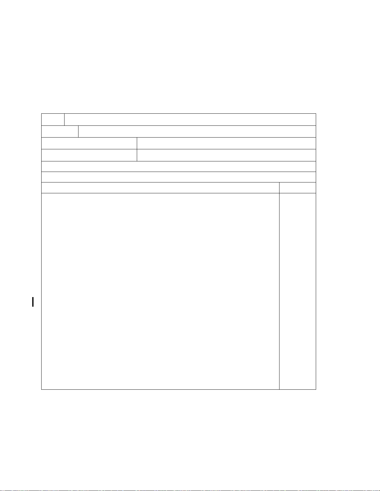
Date
Signature
Aircraft Registration Number
Aircraft Serial Number
AIR CONDITIONING SYSTEM PERIODIC INSPECTION GUIDE
INITIAL EACH ITEM AFTER ACCOMPLISHMENT
Inspect the following items every 100 hours or annually INITIAL
1. Inspect evaporator assemblies for condition, security of installation, proper
operation of blowers, and condition of drain lines.
2. Inspect the ducting for condition and security of installation.
3. Inspect the condenser blower for condition, security of installation, and proper
operation.
4. Inspect the condenser for condition and security of installation.
5. Inspect the compressor and mount for condition and security of installation.
6. Inspect the compressor drive belt for proper tension and wear.
_______
_______
_______
_______
_______
_______
7. Check the alignment of the compressor drive belt pulley to the lower pulley.
8. Inspect the receiver/drier bottle for condition and security of installation.
9. Inspect the by-pass valve for condition and security of installation.
10. Inspect the air conditioning lines for condition and security of installation.
11. Inspect placards for installation and legibility.
12. Inspect air conditioning electrical system for condition, security of installation,
and proper operation.
_______
_______
_______
_______
_______
_______
Rev. 8
4-5 May 1/17
Page 28

ENSTROM TH-28/480 SERIES MAINTENANCE MANUAL SUPPLEMENT 1
Visit www.enstromhelicopter.com for instructions to order an original manual and to register for email notification of updates.
UNCONTROLLED COPY WHEN DOWNLOADED OR PRINTED
INTENTIONALLY LEFT BLANK
Rev. 8
4-6 May 1/17
Page 29

ENSTROM TH-28/480 SERIES MAINTENANCE MANUAL SUPPLEMENT 1
Visit www.enstromhelicopter.com for instructions to order an original manual and to register for email notification of updates.
UNCONTROLLED COPY WHEN DOWNLOADED OR PRINTED
SECTION 5
SYSTEM MAINTENANCE
5-1. Belt Replacement and Adjustment, Pulley Alignment
A. Replace the compressor drive belt using the following procedure.
NOTE
Refer to the TH-28/480 Series Maintenance Manual for
maintenance procedures related to the airframe and/or aircraft
systems.
1) Remove the baggage compartment access door, transfer duct access panel,
and the forward sheet metal panels from the baggage compartment.
2) Remove the left side transfer duct and the intermediate drive shaft from
between the lower pulley assembly and the oil cooler blower.
3) Loosen the jam nuts on the tie rod located between the compressor and the
support truss, remove the upper bolt from the tie rod end to the support truss, and remove the
tension from the drive belt (Figure 2-2).
4) Remove the drive belt from the compressor pulley and the pulley on the lower
pulley assembly (Figure 2-2).
5) Install the new belt by reversing the removal process.
6) Verify the compressor pulley alignment (para. 5-1,C).
7) Adjust the belt tension (para. 5-1,B).
8) Verify the compressor pulley alignment (para. 5-1,C).
NOTE
Reset the belt tension after two hours of operation with a new belt.
9) Reinstall the transfer duct, intermediate drive shaft, and access panels.
WARNING
The following checks are to be performed by authorized
personnel.
10) Ground run the aircraft and perform a functional check of the air conditioning
system.
Rev. 8
5-1 May 1/17
Page 30

ENSTROM TH-28/480 SERIES MAINTENANCE MANUAL SUPPLEMENT 1
Visit www.enstromhelicopter.com for instructions to order an original manual and to register for email notification of updates.
UNCONTROLLED COPY WHEN DOWNLOADED OR PRINTED
NOTE
Refer to the air conditioning supplement in the applicable
Rotorcraft Flight Manual.
B. Proper compressor drive belt tension is important to insure long belt service life. Use
the following procedure to set the belt tension.
NOTE
Refer to the TH-28/480 Series Maintenance Manual for
maintenance procedures related to the airframe and/or aircraft
systems.
1) Remove the baggage compartment access door, transfer duct access panel,
and the forward sheet metal panels from the baggage compartment.
2) Remove the left side transfer duct.
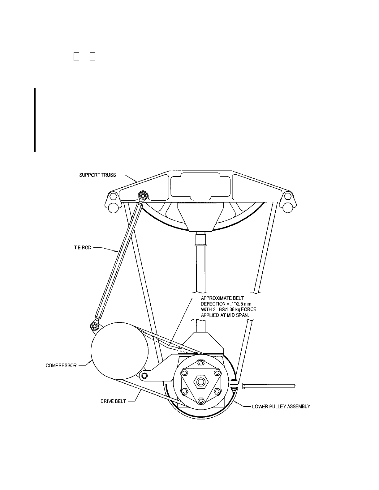
3) Using a spring scale and a straight edge, adjust the belt tension using the tie
rod, located between the compressor and support truss, until the belt deflection is approximately
.1" (2.5 mm) with 3 lbs. (1.4 kg) of force applied with the spring scale (Refer to Figure 5-1).
4) Reinstall the transfer duct and access panels.
WARNING
The following checks are to be performed by authorized
personnel.
5) Ground run the aircraft and perform a functional check of the air conditioning
system.
NOTE
Refer to the air conditioning supplement in the applicable
Rotorcraft Flight Manual.
NOTE
Check/Reset the belt tension after two hours of operation with a
new belt.
C. Proper compressor pulley alignment is important to insure long belt service life. Use
the following procedure to adjust the pulley alignment.
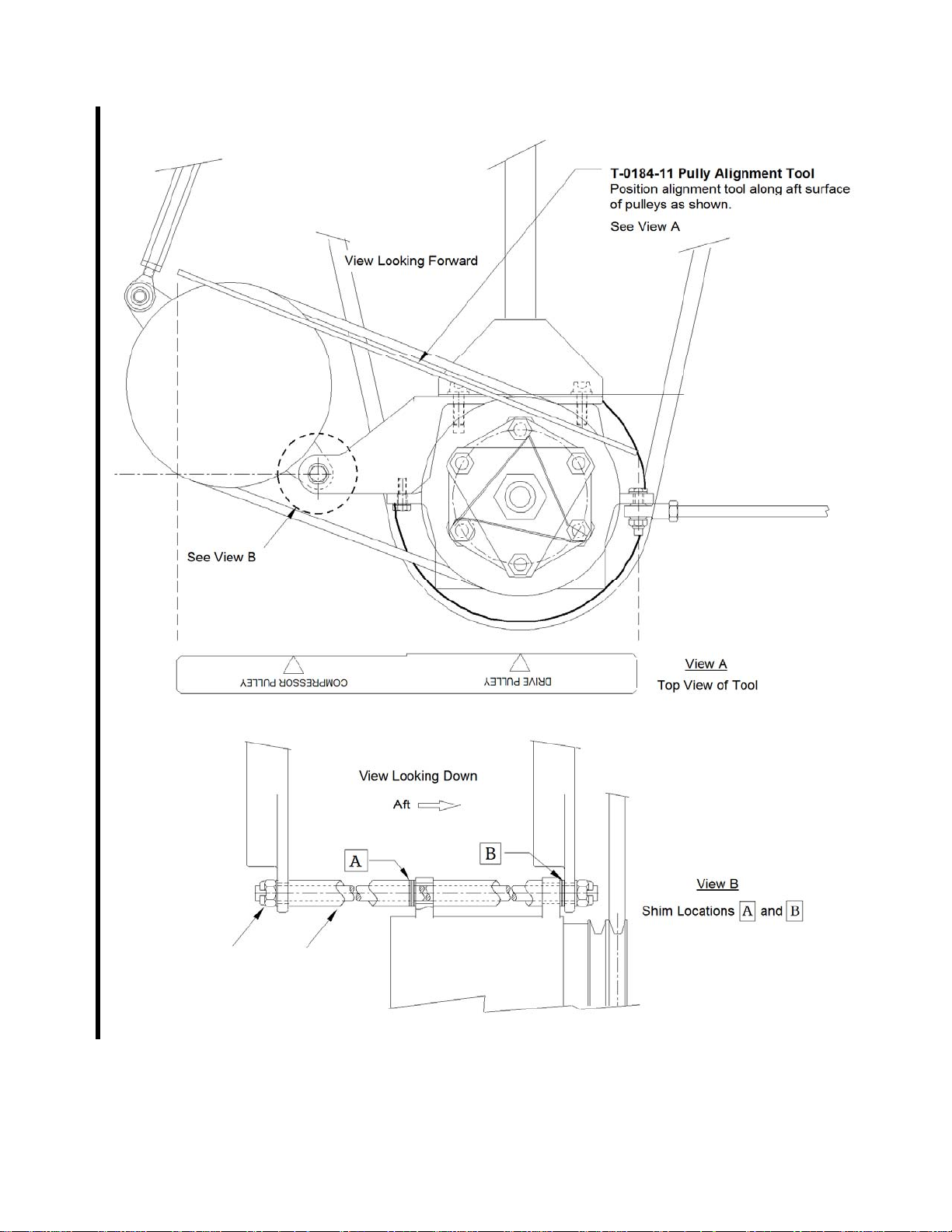
1) Position the pulley alignment tool, T-0184-11, along the aft surfaces the
compressor pulley and the drive pulley (Figure 5-2).
Rev. 8
5-2 May 1/17
Page 31
ENSTROM TH-28/480 SERIES MAINTENANCE MANUAL SUPPLEMENT 1
Visit www.enstromhelicopter.com for instructions to order an original manual and to register for email notification of updates.
UNCONTROLLED COPY WHEN DOWNLOADED OR PRINTED
2) If a gap is present between the compressor pulley and the tool, shim at
locations A or B with AN960616L washers, as required. To add shims, remove the nuts on the
lower compressor support rod. Remove rod and spacers and add shims. Ensure that the
spacers are positioned properly when reassembling (longer spacer is forward and the shorter
spacer is aft) (Refer to Figure 5-2).
NOTE
After the compressor pulley alignment is accomplished, the nuts
installed on the lower compressor support rod must be torqued
(Figure 5-2, Item 34).
3) Torque the nuts to 160-190 in-lb/18.1-21.4 Nm and safety.
Figure 5-1. Belt Tensioning
Rev. 8
5-3 May 1/17
Page 32
ENSTROM TH-28/480 SERIES MAINTENANCE MANUAL SUPPLEMENT 1
Visit www.enstromhelicopter.com for instructions to order an original manual and to register for email notification of updates.
UNCONTROLLED COPY WHEN DOWNLOADED OR PRINTED
Figure 5-2. Pulley Alignment Tool Position, Shim Locations
Rev. 8
5-4 May 1/17
Page 33

ENSTROM TH-28/480 SERIES MAINTENANCE MANUAL SUPPLEMENT 1
Visit www.enstromhelicopter.com for instructions to order an original manual and to register for email notification of updates.
UNCONTROLLED COPY WHEN DOWNLOADED OR PRINTED
5-2. Refrigerant Fitting Installation
A. Two types of refrigerant plumbing fittings are used in the air conditioning system. The
first is an "Insert O-ring Fitting". The location of this type of fitting is marked by this symbol "●"
on the plumbing schematics in Appendix A. The other type of fitting is a "Face Seal O-ring
Fitting". The location of this type of fitting is marked by this symbol "
paragraphs for instructions on installing the fittings.
NOTE
A light coat of refrigerant oil should be applied to all O-rings and to
the face of the flare fittings prior to assembly.
B. Install the “Insert O-ring Fitting” as follows:
NOTE
The O-rings used with the "Insert O-ring Fitting" are green in color.
¤ ". Refer to the following
1) Apply a light coat of refrigerant oil to the O-ring and the female fitting.
2) Install the O-ring onto the male side of the fitting (hose).
3) Slide the "B" nut back away from the male fitting and carefully insert the male
fitting into the female fitting. Be careful to maintain alignment and do not pinch the O-ring when
connecting the fittings.
NOTE
The male fitting should seat fully against the female fitting without
the O-ring being pinched between.
4) Hold the fittings together while sliding the "B" nut forward and engaging the
threads. Tighten the "B" nut and torque to the specifications in Table 5-1.
Table 5-1. Fitting Torque Specifications
Fitting Size
#6 30-35 in-lbs (3.4-3.9 Nm)
Torque
#8 40-45 in-lbs (4.5-5.1 Nm)
#10 50-55 in-lbs (5.7-6.2 Nm)
Rev. 4
5-5 Mar 17/09
Page 34

ENSTROM TH-28/480 SERIES MAINTENANCE MANUAL SUPPLEMENT 1
Visit www.enstromhelicopter.com for instructions to order an original manual and to register for email notification of updates.
UNCONTROLLED COPY WHEN DOWNLOADED OR PRINTED
C. Install the "Face Seal O-ring Fitting" as follows:
NOTE
The O-rings used with the "Face Seal O-ring Fitting" are black in
color.
1) Apply a light coat of refrigerant oil to the O-ring and install the O-ring into the
female fitting.
2) Assemble and tighten the fitting. Torque the fitting as specified in the
previous sub-paragraph.
D. Leak check the system after the fittings are assembled. Torque seal (paint stripe) the
"B" nuts after the system is sealed.
5-3. Leak Check
NOTE
Identification and elimination of any system fitting leaks is
extremely important to insure a trouble free system.
A. A system which contains a partial charge can be leak tested and recharged without
evacuating the system. The system can be pressurized with nitrogen or R134a refrigerant. An
evacuated system should be filled to a pressure of 60-80 psi (414-552 kPa) of refrigerant or 150
psi (1034 kPa) of nitrogen prior to leak testing. The system should be leak tested using a
combination of soap solution and an electronic leak detector.
NOTE
Do not use compressed air for the leak check. Compressed air
can introduce moisture into the system which will cause it to
operate poorly or not at all.
B. The initial leak check can be accomplished using a nitrogen pressure charge and a
soap solution. Each fitting should be checked and repaired prior to charging the system with
refrigerant.
C. Once the nitrogen check is complete, the system must be checked with a refrigerant
charge. Evacuate the system and service to 60-80 psi (414-552 kPa) with refrigerant. Use an
electronic leak detector to check each connection in the system. Since the refrigerant is heavier
than air, leaks are most likely detected on the underside of hoses and fittings. Refrigerant will
also collect in low areas and give an erroneous leak indication. Directing a stream of shop air
through the area just prior to testing will help to eliminate any erroneous indications. If a leak is
detected at an O-ring fitting, reclaim the system and install a new O-ring. A small amount of
leakage, about one ounce (.03 kg) per year, past the compressor shaft seal is normal. Most
electronic leak detectors are sensitive enough to show a leak of this magnitude.
Rev. 4
5-6 Mar 17/09
Page 35
ENSTROM TH-28/480 SERIES MAINTENANCE MANUAL SUPPLEMENT 1
Visit www.enstromhelicopter.com for instructions to order an original manual and to register for email notification of updates.
UNCONTROLLED COPY WHEN DOWNLOADED OR PRINTED
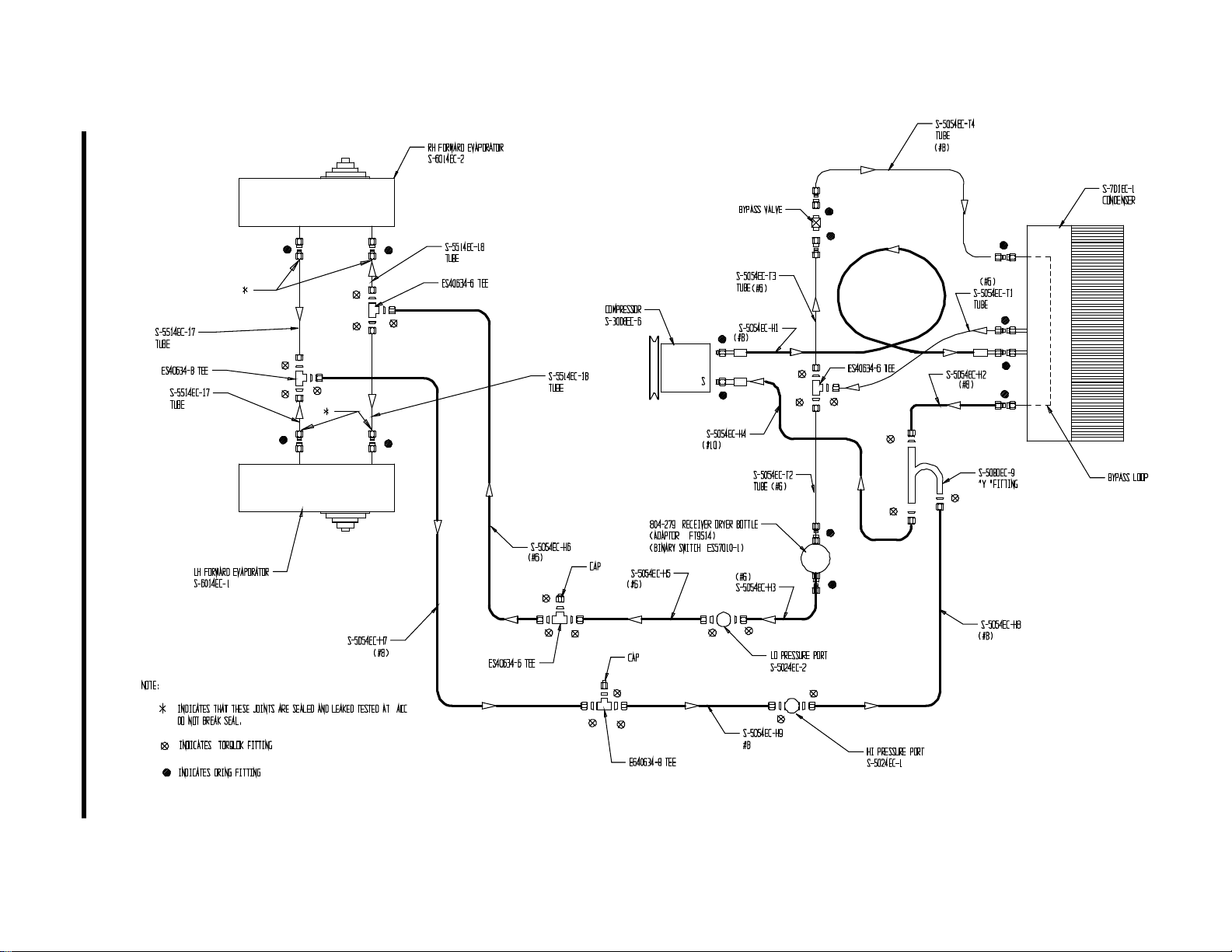
A-1. Plumbing Schematic Diagram – Two Evaporator System (Two Forward), P/N 4220176-1
Rev. 7
A-1 Jun 14/11
Page 36
ENSTROM TH-28/480 SERIES MAINTENANCE MANUAL SUPPLEMENT 1
Visit www.enstromhelicopter.com for instructions to order an original manual and to register for email notification of updates.
UNCONTROLLED COPY WHEN DOWNLOADED OR PRINTED
A-2. Plumbing Schematic Diagram – Three Evaporator System (Two Forward, One Aft), P/N 4220176-2
Rev. 7
A-2 Jun 14/11
Page 37
ENSTROM TH-28/480 SERIES MAINTENANCE MANUAL SUPPLEMENT 1
Visit www.enstromhelicopter.com for instructions to order an original manual and to register for email notification of updates.
UNCONTROLLED COPY WHEN DOWNLOADED OR PRINTED
A-3. Plumbing Schematic Diagram – Two Evaporator, Litter Compatible System (One Forward, One Aft), P/N 4220176-3
Rev. 7
A-3 Jun 14/11
Page 38

ENSTROM TH-28/480 SERIES MAINTENANCE MANUAL SUPPLEMENT 1
Visit www.enstromhelicopter.com for instructions to order an original manual and to register for email notification of updates.
UNCONTROLLED COPY WHEN DOWNLOADED OR PRINTED
INTENTIONALLY LEFT BLANK
Rev. 3
A-4 Sep 12/08
Page 39
ENSTROM TH-28/480 SERIES MAINTENANCE MANUAL SUPPLEMENT 1
Visit www.enstromhelicopter.com for instructions to order an original manual and to register for email notification of updates.
UNCONTROLLED COPY WHEN DOWNLOADED OR PRINTED
B-1. Electrical Schematic Diagram – Two Evaporator System (Two Forward), P/N 4220176-1 or 4220176-5
Rev. 5
B-1 Dec 3/10
Page 40
ENSTROM TH-28/480 SERIES MAINTENANCE MANUAL SUPPLEMENT 1
Visit www.enstromhelicopter.com for instructions to order an original manual and to register for email notification of updates.
UNCONTROLLED COPY WHEN DOWNLOADED OR PRINTED
B-2. Electrical Schematic Diagram – Three Evaporator System (Two Forward, One Aft), P/N 4220176-2 or 4220176-6
Rev. 5
B-2 Dec 3/10
Page 41
ENSTROM TH-28/480 SERIES MAINTENANCE MANUAL SUPPLEMENT 1
Visit www.enstromhelicopter.com for instructions to order an original manual and to register for email notification of updates.
UNCONTROLLED COPY WHEN DOWNLOADED OR PRINTED
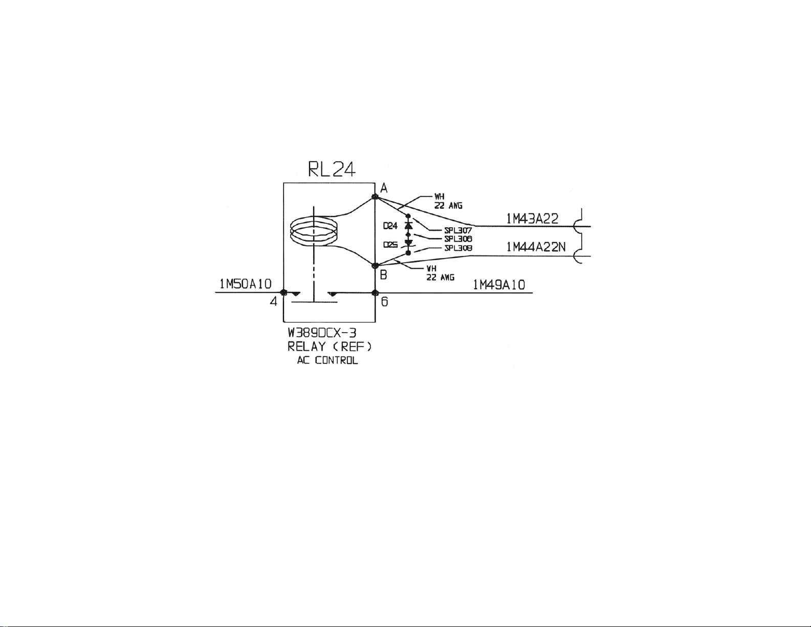
B-3. Electrical Schematic Diagram – Transient Suppression Circuitry
Rev. 5
B-3 Dec 3/10
Page 42
ENSTROM TH-28/480 SERIES MAINTENANCE MANUAL SUPPLEMENT 1
Visit www.enstromhelicopter.com for instructions to order an original manual and to register for email notification of updates.
UNCONTROLLED COPY WHEN DOWNLOADED OR PRINTED
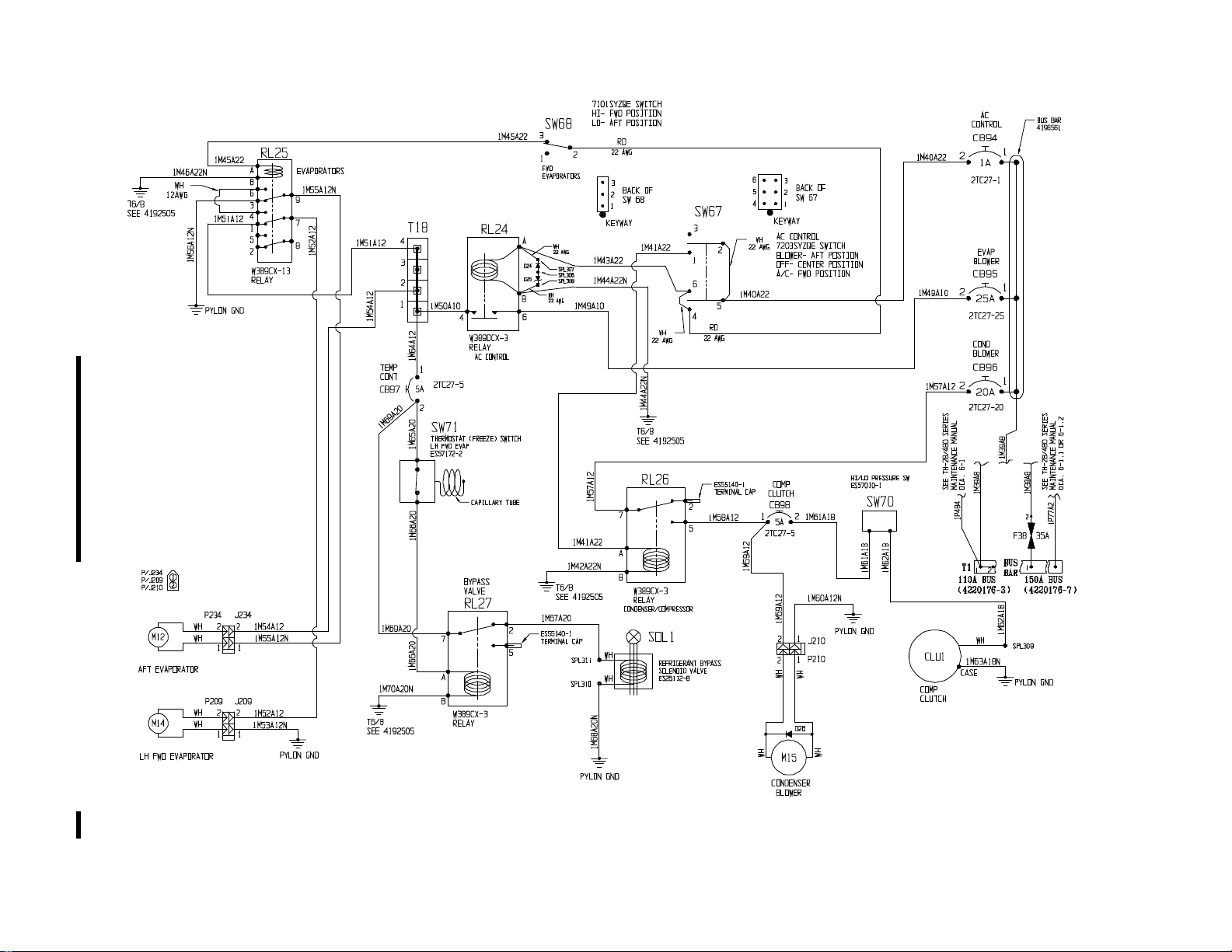
B-4. Electrical Schematic Diagram – Two Evaporator, Litter Compatible System (One Forward, One Aft), P/N 4220176-3 or 4220176-7
Rev. 5
B-4 Dec 3/10
 Loading...