

ENSTROM 280FX Series, F28-F Series Pilot's Manual

Piill
P
ott
o
G
G
Trr
T
uii
u
aii
a
d
e
d
e
nii
n
n
n
g
g
MMaarrcchh 1100,, 22000088
Enstrom Helicopter Corporation 1
Menominee, Michigan 49858-0490 U.S.A.
FFoorr ttrraaiinniinngg ppuurrppoosseess oonnlly
Phone (906) 863-1200
22000088 EEddiittiioonn 22
Post Office Box 490
y

Table of Contents
Introduction 3
Aircraft Description & Construction Details 4
Aircraft servicing 18
Aircraft Systems 20
Electrical 20
Caution and Warning 24
Instruments 29
Fuel System 32
Power Train 34
Flight Controls 39
Power Plant 42
Operation Procedures 48
Airframe 48
Powerplant 55
Weight & Balance 61
Performance 63
Emergency 69
Prefight 78
Pilot Notes 84
Enstrom Helicopter Corporation 2
Post Office Box 490
Menominee, Michigan 49858-0490 U.S.A.
Phone (906) 863-1200
INTRODUCTION
Enstrom 280FX and F28-F series Helicopter Pilot Training
Course Objectives
The purpose of this course is to prepare an experienced helicopter pilot for a
smooth transition into the Enstrom Piston powered helicopters.
This course includes descriptions and theory of operation for the systems, and
the location of the system components.
The course also includes the description of the pilot pre-flight procedures and the
pilots are expected to perform these pre-flight Inspections.
Enstrom Helicopter Corporation 3
Post Office Box 490
Menominee, Michigan 49858-0490 U.S.A.
Phone (906) 863-1200
AIRCRAFT DESCRIPTON & CONSTRUCTION DETAILS
GENERAL DESCRIPTION
The Enstrom 280FX and F28-F helicopters are 3 bladed, single engine
helicopters manufactured by the Enstrom Helicopter Corporation and certified by
the FAA under part 6 of the Civil Air Regulations.
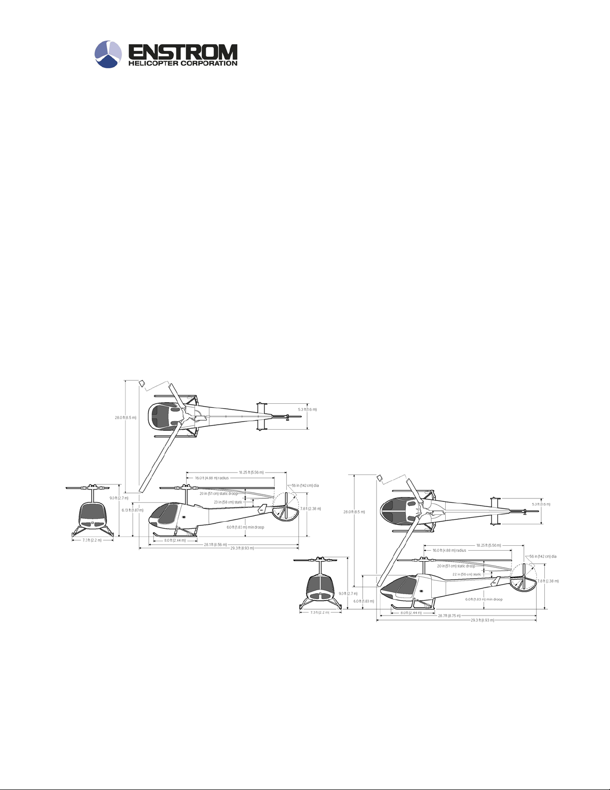
Turning Radius
The turning radius is about 23 feet when pivoted on the wheels about the mast.
Principal Dimensions
Enstrom Helicopter Corporation 4
Post Office Box 490
Menominee, Michigan 49858-0490 U.S.A.
Phone (906) 863-1200
CHARACTERISTICS
Helicopter description
The Enstrom 280FX and F28 F helicopters are a single engine, piston powered
helicopter certified for day and night VFR flight and that can be equipped for IFR
flight training. The F28 F helicopter was originally certified in 1980 and the 280
FX in 1985 to the CAR 6 regulations.
Early F28 F and 280F helicopters were certified to 2350 lb maximum gross
weight and can be changed to 2600 lb gross weight by incorporating the
appropriate modifications.
Enstrom Helicopter Corporation 5
Post Office Box 490
Menominee, Michigan 49858-0490 U.S.A.
Phone (906) 863-1200

Beginning in 1984, F28 F and 280FX helicopters were produced with the gross
weight limitation of 2600 pounds.
Enstroms are relatively quiet helicopters due to the installation of the turbocharger, and the slow turning main and tail rotors. They can be equipped with an
optional secondary muffler that lowers the noise signature significantly.
All Enstrom helicopters feature a three bladed, fully articulated main rotor system
which has over 4,000,000 flight hours and which has never had a catastrophic
failure or thrown a blade. The tail rotor is two bladed and completely unblocked
for exceptional effectiveness. Due to the high inertia rotor design, the helicopter
possesses out-standing auto-rotational capabilities.
In addition to being a versatile and crashworthy helicopter, the 280FX and F28 F
helicopters were designed to be procured and operated for minimum costs. The
helicopter does not require hydraulic boost or stability augmentation systems.
The limited number of fatigue critical parts, the long overhaul intervals, and the
low hour/flight ratio resulting from high reliability and easy maintenance combine
to yield low operation and support costs.
Enstrom Helicopter Corporation 6
Post Office Box 490
Menominee, Michigan 49858-0490 U.S.A.
Phone (906) 863-1200
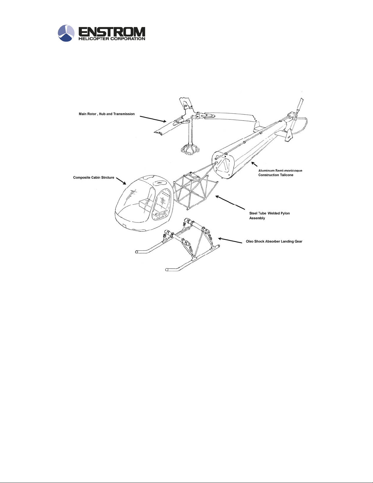
CONSTRUTION DETAILS
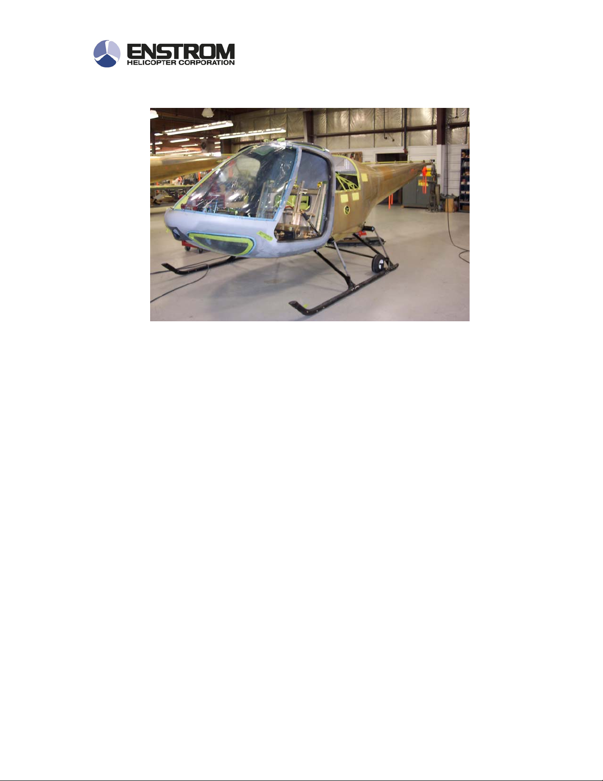
Fuselage
The fuselage is the forward section of the airframe extending from the nose to
the forward end of the tailcone. The cabin shell is molded out of fiberglass and
the aluminum seat and floor structure is fabricated and then bonded into the
fiberglass shell.
The pylon structure is welded up out of high carbon molybdenum steel. The
landing gear, cabin and tail cone are bolted on to the pylon structure. The engine
and main rotor transmission are also attached to the pylon.
Enstrom Helicopter Corporation 7
Post Office Box 490
Menominee, Michigan 49858-0490 U.S.A.
Phone (906) 863-1200
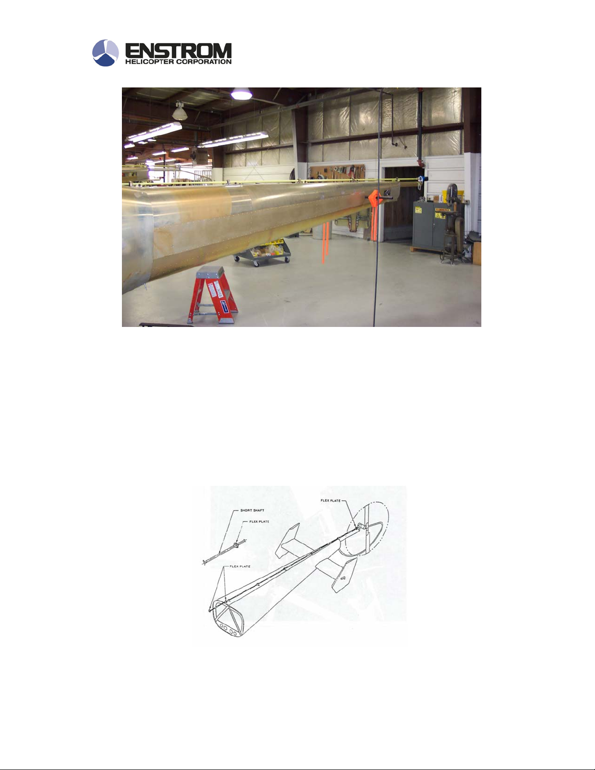
Tailcone
The tail cone is bolted to the aft end of the pylon. It is a tapered semimonocoque structure comprised of skins, bulkheads, longerons and stringers.
The tailcone supports the tail rotor, tail-rotor transmission, horizontal and vertical
stabilizers, and the tail-rotor guard. It houses the tail rotor drive shaft and can be
used to mount some of the helicopter electrical equipment.
Enstrom Helicopter Corporation 8
Post Office Box 490
Menominee, Michigan 49858-0490 U.S.A.
Phone (906) 863-1200
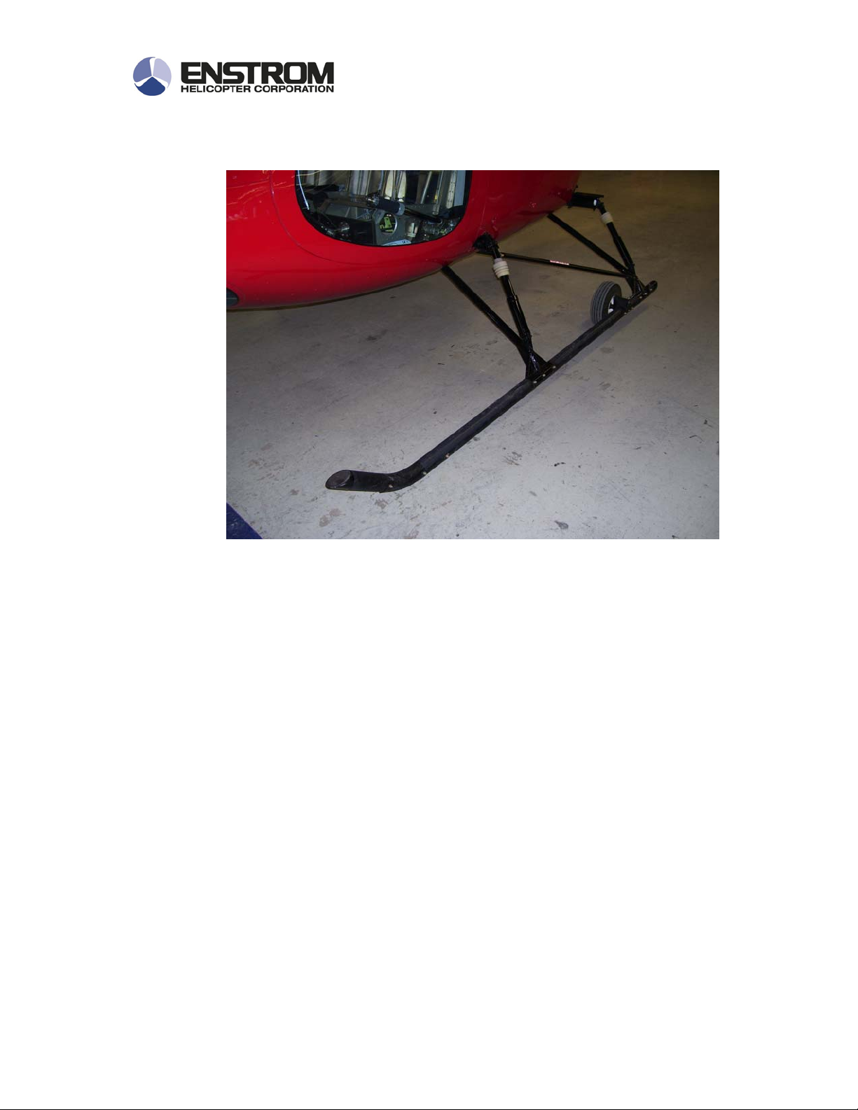
Landing Gear
Main Landing Gear: The main landing gear consists of two tubular
aluminum skids attached to the airframe by means of the forward and aft cross
tubes through four air-oil oleo struts. The struts cushion ground contact during
landing.
Drag struts give the gear stability and strength and prevent fore and aft
movement during ground contact maneuvers. Due to their design, the drag struts
will sustain landings with significant forward movement of the helicopter;
however, landing with rearward movement may overload the structure and cause
its collapse.
Replaceable hardened steel skid shoes are installed on each skid to resist
skid wear on hard surfaces.
Enstrom Helicopter Corporation 9
Post Office Box 490
Menominee, Michigan 49858-0490 U.S.A.
Phone (906) 863-1200
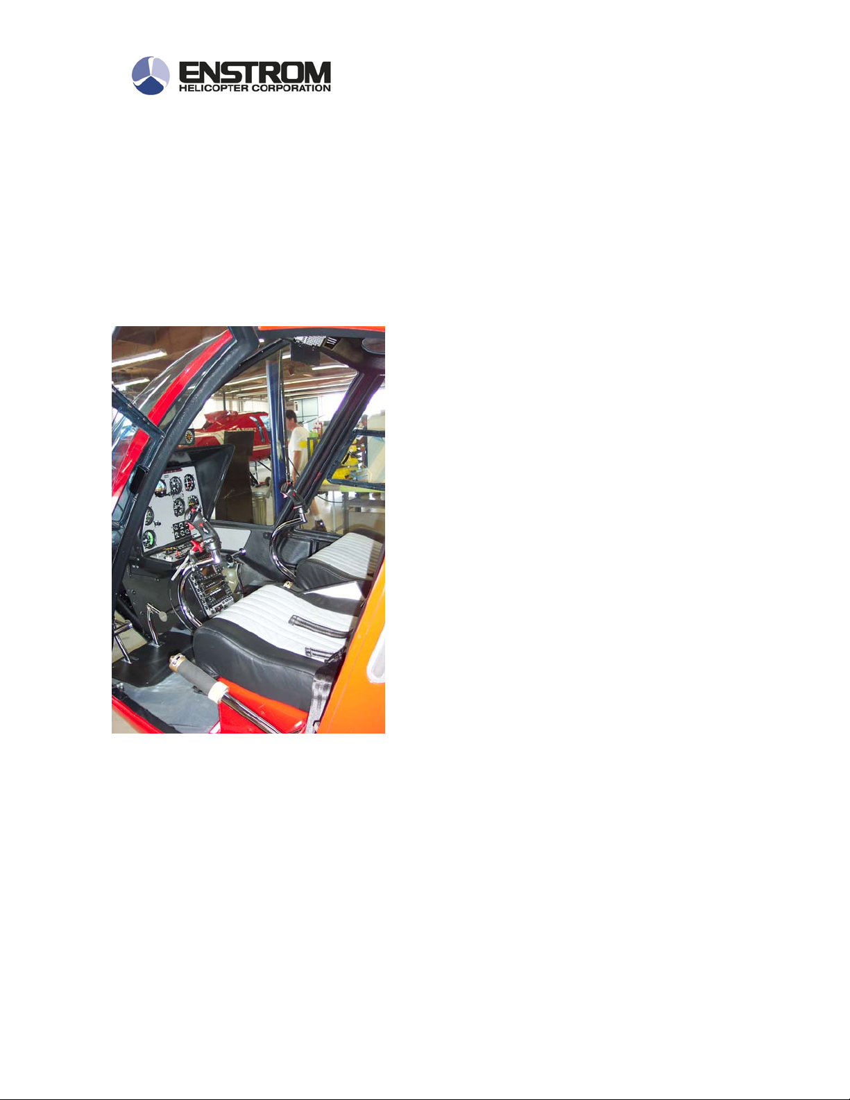
Crew Compartment
The crew compartment consists of pilot and
passenger/co-pilot seating, Instrument
panel, radio console and pilot and co-pilot
flight controls mounted to the aluminum floor
structure and enclosed in the fiberglass
cabin shell.
The co-pilot controls are removable and a
seat cushion for the third passenger is
inserted into the space vacated when the
co-pilot collective is removed.
Enstrom Helicopter Corporation 10
Post Office Box 490
Menominee, Michigan 49858-0490 U.S.A.
Phone (906) 863-1200
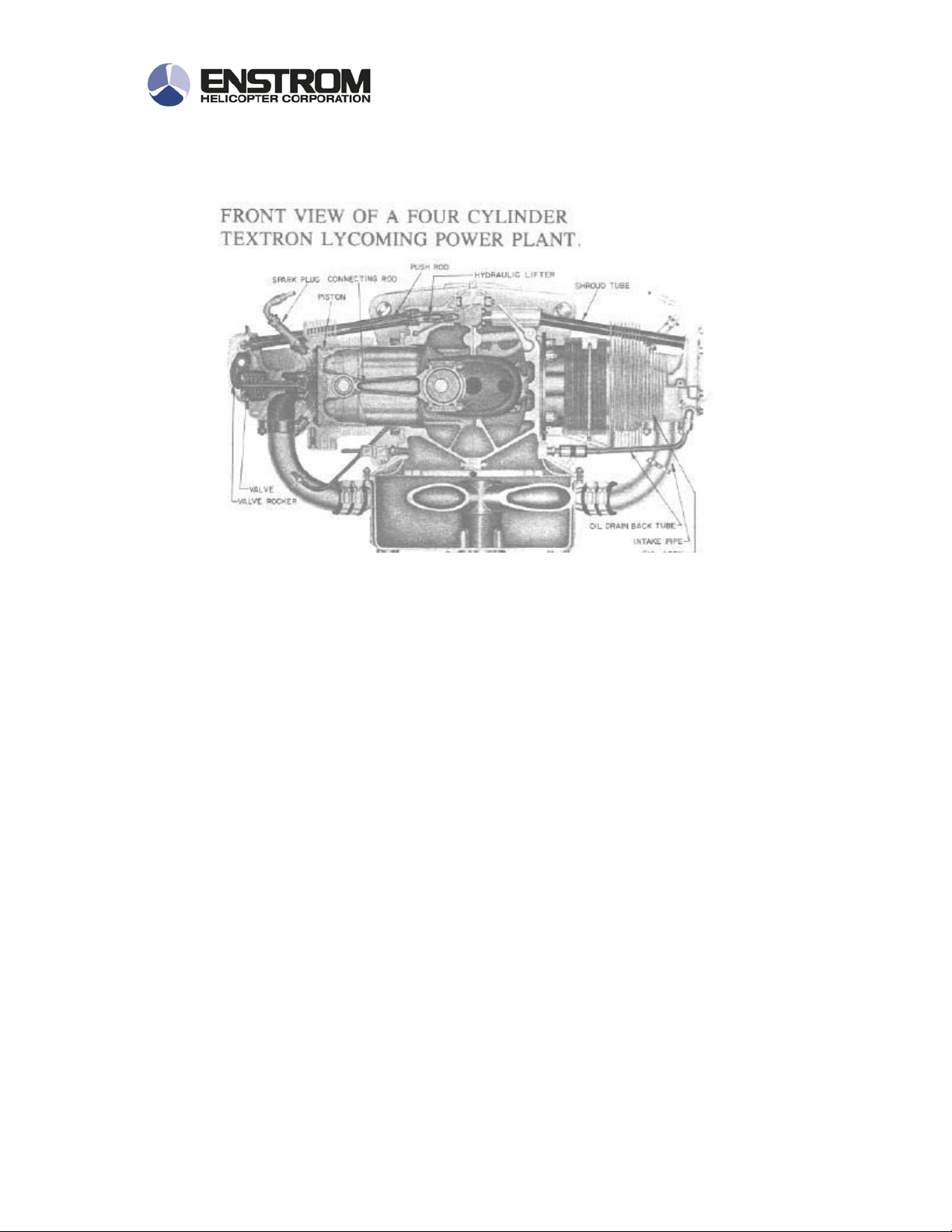
Engine
The piston powered Enstrom helicopters are powered by a Lycoming built HIO360-FIAD four cylinder, air cooled engine that produces 225 Shaft Horse Power.
The maximum horsepower is achieved with the aid of a Kelley Aerospace
turbocharger that incorporates an adjustable waste gate that is controlled by a
breakaway control rod.
The engine is cooled by a large fan that is installed between the crankshaft and
the lower belt pulley. Cooling air for the engine is drawn in from the overhead
scoop mounted behind the main rotor mast, through the fan and then around the
cylinders and through the oil coolers.
There are clean out traps mounted adjacent to the two oil coolers to facilitate
cleaning out debris.
Enstrom Helicopter Corporation 11
Post Office Box 490
Menominee, Michigan 49858-0490 U.S.A.
Phone (906) 863-1200
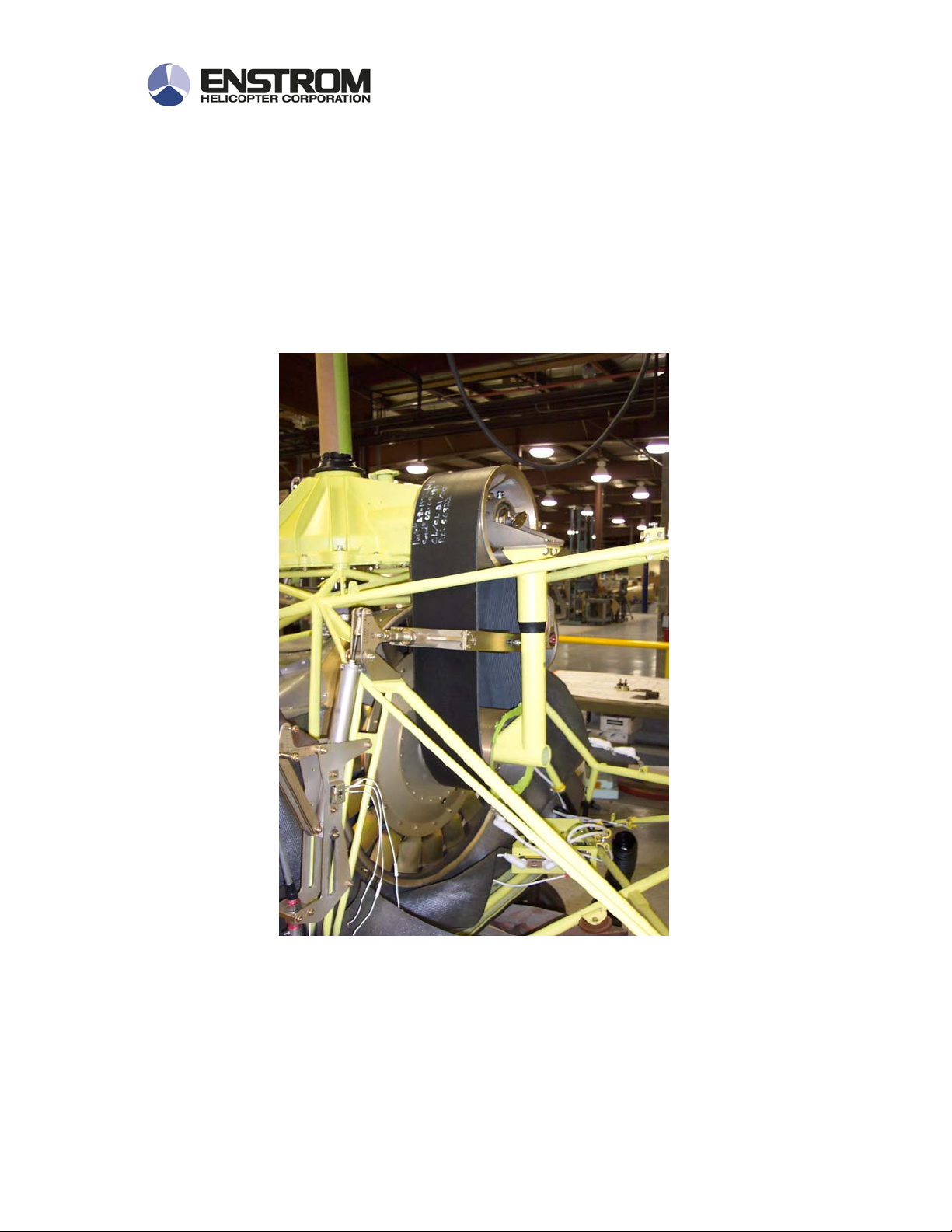
Power Train
The power train includes the main rotor transmission, an upper pulley assembly
incorporating the overrunning clutch, jack strut, drive belt, lower pulley, drive
shaft and tail rotor gearbox.
Enstrom Helicopter Corporation 12
Post Office Box 490
Menominee, Michigan 49858-0490 U.S.A.
Phone (906) 863-1200
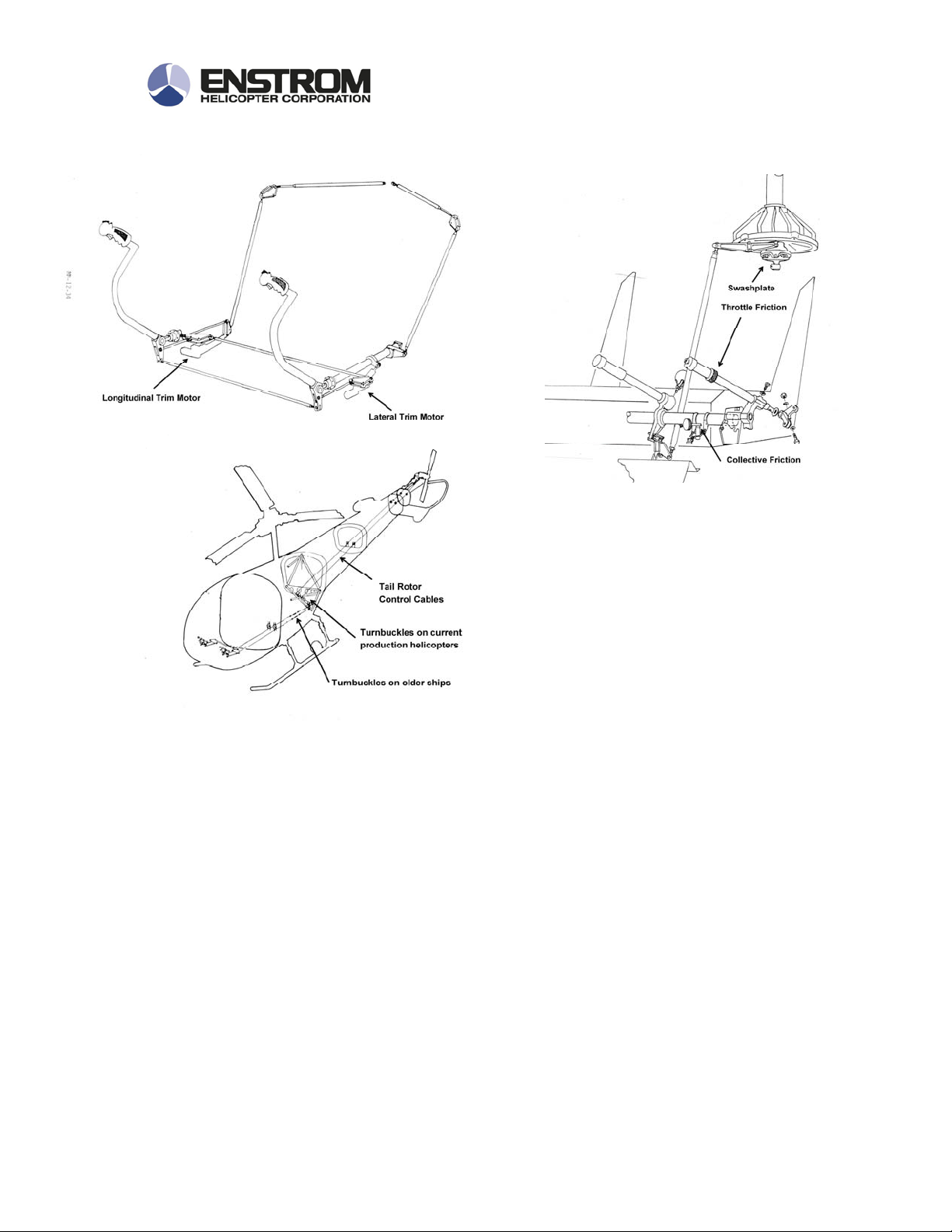
Flight Controls
The flight controls include three primary systems: the collective, cyclic, and antitorque or directional controls. There is no hydraulic system installed on Enstrom
Helicopters, cyclic forces are relieved using electric mechanical trim motor
operated spring capsules. Collective forces are managed using a spring capsule
assembly.
The helicopters also have fixed horizontal and vertical stabilizers that are
mounted on the tail cone to help provide stability and attitude control during
forward flight.
Enstrom Helicopter Corporation 13
Post Office Box 490
Menominee, Michigan 49858-0490 U.S.A.
Phone (906) 863-1200

Main Rotor System
The main rotor system is a three bladed, high inertia, fully articulated rotor
system. The main rotor hub assembly is composed of two opposing forged
aluminum hub plates separated by an aluminum cylindrical spacer. Through
bolts hold these items together along with steel spline adapters.
Three steel universal blocks are mounted on roller bearing units that permit
flapping and lead-lag motions. Laminated phenolic pads are used to limit blade
travel in both the lead-lag and flapping axes. A thrust nut on the bottom of each
universal block transfers vertical blade forces to both hub plates through the
universal block.
Enstrom Helicopter Corporation 14
Post Office Box 490
Menominee, Michigan 49858-0490 U.S.A.
Phone (906) 863-1200
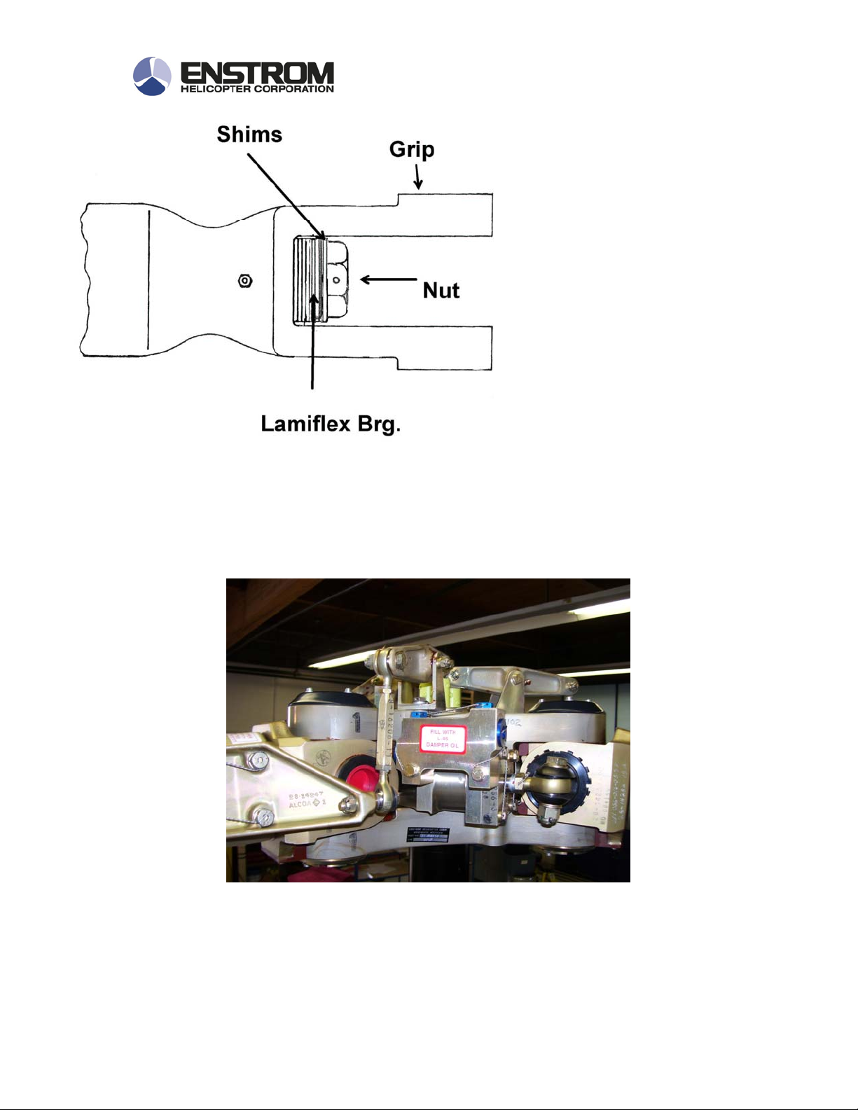
The rotor blades are
secured to each universal
block on the hub through a
forged aluminum grip which
is in turn secured to a steel
spindle assembly through an
elastomeric feather bearing
(Lamiflex Bearing) and a
retention nut.
Closed circuit hydraulic dampers are incorporated between each flapping pin and
the rotor hub to limit the lead-lag velocity of the blades. Because the hydraulic
dampers have no centering spring, they are quite limber; this, coupled with the
large heavy blades causes the ground rock that is often experienced while the
helicopter rotor system is spooling up.
Enstrom Helicopter Corporation 15
Post Office Box 490
Menominee, Michigan 49858-0490 U.S.A.
Phone (906) 863-1200

The main rotor blades are of hollow construction consisting of an extruded
leading edge spar, with a 7 degree twist, to which is bonded upper and lower
aluminum skins. The blade root is composed of a bonded doubler assembly.
A single retention pin connects the blade root to the grip and a non-adjustable
drag brace connects the trailing edge of the blade to the grip.
A cap is bonded to the tip of each blade in which there are provisions for
spanwise and cordwise balance weights. Two tracking tabs are riveted to the
trailing edge of each blade.
Enstrom Helicopter Corporation 16
Post Office Box 490
Menominee, Michigan 49858-0490 U.S.A.
Phone (906) 863-1200
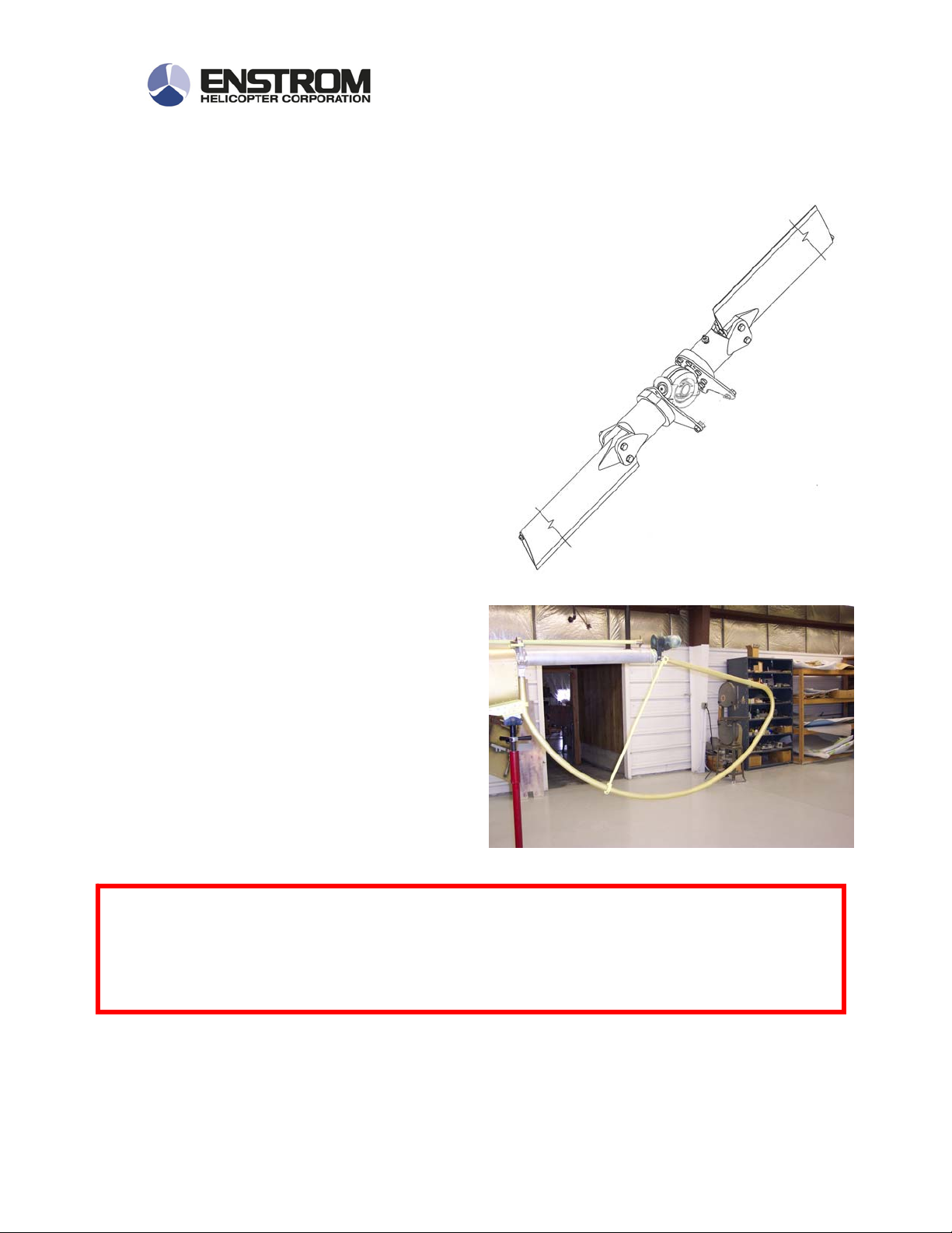
Tail Rotor Assembly
The tail rotor assembly is a two
bladed, wide cord, teetering, delta hinged
rotor assembly.
The fly-weights on the blade
retention plates unload the tail rotor
twisting forces in flight so that the pilot
does not need to carry left pedal at cruse
power settings. They are weighted so
that when the aircraft is being flown at
approximately 29 in mp, the pedals are
neutralized and the slip ball centered.
For this reason, the aircraft requires very
little left pedal in hover and in climb, and
significant right pedal in low power
situations.
Tail Rotor Guard: A tubular
aluminum tail rotor guard is installed on
the aft end of the tailcone. It aids in
ground handling and protecting the tail
rotor from damage while the helicopter
is on the ground.
The tail rotor guard will not prevent damage to the tail rotor in the event
IMPORTANT!
of a hard landing.
Enstrom Helicopter Corporation 17
Post Office Box 490
Menominee, Michigan 49858-0490 U.S.A.
Phone (906) 863-1200

SERVICING
Fuel
100/130 Aviation Grade Mil-G-5572
100LL Aviation Grade
Engine Lubrication Oils
Oil, Ashless Dispersant MIL-L-22851
Flight Control Lubricants
Grease, MIL-G-81322 (Mobil 28, Shell 22)
Landing Gear Oleos
Oil, MIL-H-5606
Nitrogen
Main Rotor Dampers
Oil, L-45 Silicone Oil (GE Silicone L-45-20)
Main and Tail Transmissions
Oil, MIL-PRF-2105 (Mobil 1 Gear Oil (Mobil 1 Synthetic Gear
Lubricant (75W-90)
Enstrom Helicopter Corporation 18
Post Office Box 490
Menominee, Michigan 49858-0490 U.S.A.
Phone (906) 863-1200

Overrunning Clutch
Oil, MIL-L-23699 (Mobil Jet II, Shell Turbine Oil 500 or equivalent)
Tach
Drive Cables
Grease, 2701-109 (S.S. White CO, LPS 2)
Notes:
Landing gear oleos should be serviced with the weight of the helicopter off of the
landing gear, and should be all serviced at the same time or at the very least, in
pairs, front and back.
Enstrom Helicopter Corporation 19
Post Office Box 490
Menominee, Michigan 49858-0490 U.S.A.
Phone (906) 863-1200
AIRCRAFT SYSTEMS
ELECTRICAL SYSTEMS
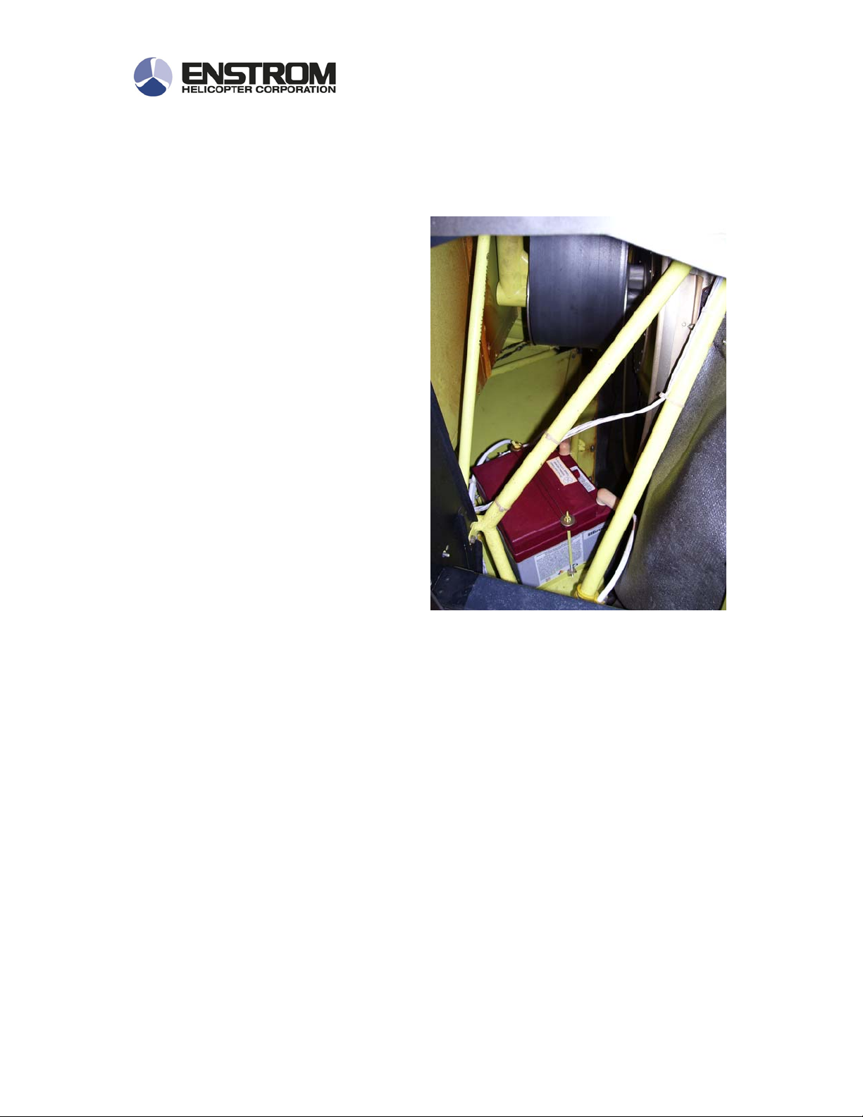
Most helicopters manufactured after
the mid 1990’s have 24 volt electrical
systems with the battery mounted
under the baggage compartment. On
earlier 12 volt helicopters, the battery
is installed under the co-pilot seat.
Description – Starter / Generator Systems
The starter on current production Enstrom 280FX and F28-F helicopters consists
of a Skytech manufactured high-speed starter mounted on the engine, behind the
main oil cooler driving on a ring gear that is mounted on the outside of the
engine flywheel.
A 24 volt battery is mounted just aft of the engine and below the baggage
compartment on the right side of the aircraft. The starter solenoid is mounted on
the battery tray, and the master switch solenoid is mounted on the firewall just
inboard of the engine air cleaner. The aux power plug is mounted above the oil
cooler, inside the right engine cowl door.
Master Solenoid
Enstrom Helicopter Corporation 20
Post Office Box 490
Menominee, Michigan 49858-0490 U.S.A.
Phone (906) 863-1200
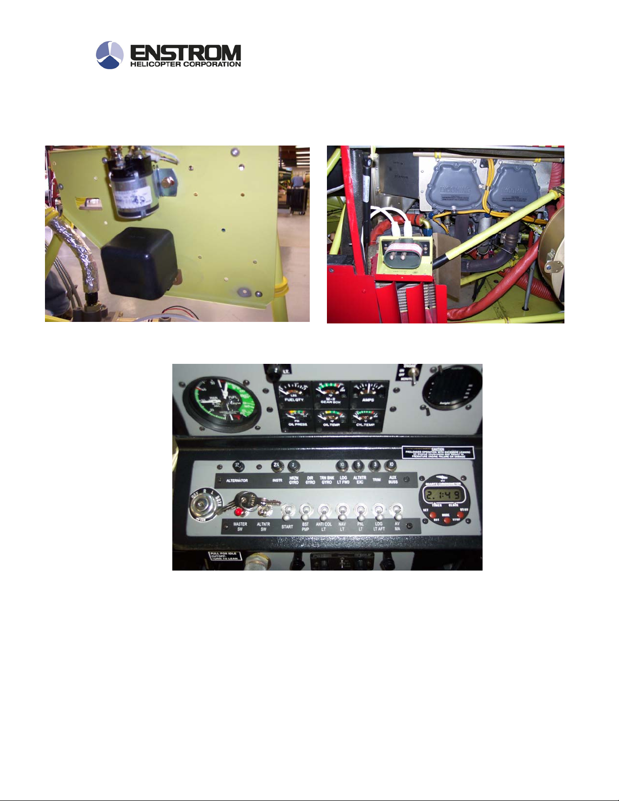
The master switch on the instrument panel energizes the master switch relay
which powers up the helicopter systems. The alternator switch powers the
voltage regulator which controls the alternator output. The start switch energizes
the starter button on the pilot collective.
Enstrom Helicopter Corporation 21
Post Office Box 490
Menominee, Michigan 49858-0490 U.S.A.
Phone (906) 863-1200

Starting systems
For aircraft starting the master switch, alternator switch, and the start switch are
placed in the on position, and the magneto switch is placed in the both position..
If an APU unit is used, the alternator switch is left in the off position. When the
starter switch on the collective is pressed, the starter solenoid energizes the
starter and the starting vibrator.
The starting vibrator has an internal relay that switches off the right magneto for
starting and that directs a hot steady spark through the left magneto and the
retard points to the spark plugs. This is to facilitate the start and prevent the
engine from kicking back. It’s important to note that the starting vibrator requires
over 13 volts to operate (24 volt systems) so the engine generally will not start if
it is cranked with a low battery. (9 volts is required to start 12 volt systems)
NOTE
The engine magneto develops electrical power to fire the sparkplugs
internally and there is no connection between the magneto and the
Because the magneto is not connected to the helicopter electrical system, turning
off the battery switch while flying will not affect the operation of the engine,
except that the electric boost pump will not operate.
NEVER PERFORM A MAGNETO CHECK IN A HELICOPTER WHILE
FLYING. IF THE ENGINE IS SWITCHED TO AN INPERATIVE
MAGNETO THE ENGINE WILL STOP RUNNING.
helicopter electrical system.
IMPORTANT
Enstrom Helicopter Corporation 22
Post Office Box 490
Menominee, Michigan 49858-0490 U.S.A.
Phone (906) 863-1200
Alternator Systems
The electrical generating system in the 280 FX and the F28-F consists of the 24
volt battery, 60 amp alternator and a solid state voltage regulator. Power to the
voltage regulator is controlled by the switch marked Alternator on the instrument
consol switch panel. When the switch is turned on, the voltage regulator is
energized which then controls the voltage produced by the alternator by varying
the field voltage.
The battery is located behind the engine, just under the forward side of the
baggage compartment, and the voltage regulator is located under the right side
of the co-pilot seat. The alternator is located on the aft left side of the engine
compartment and the alternator belt can be inspected through a removable panel
just above the auxiliary oil cooler.
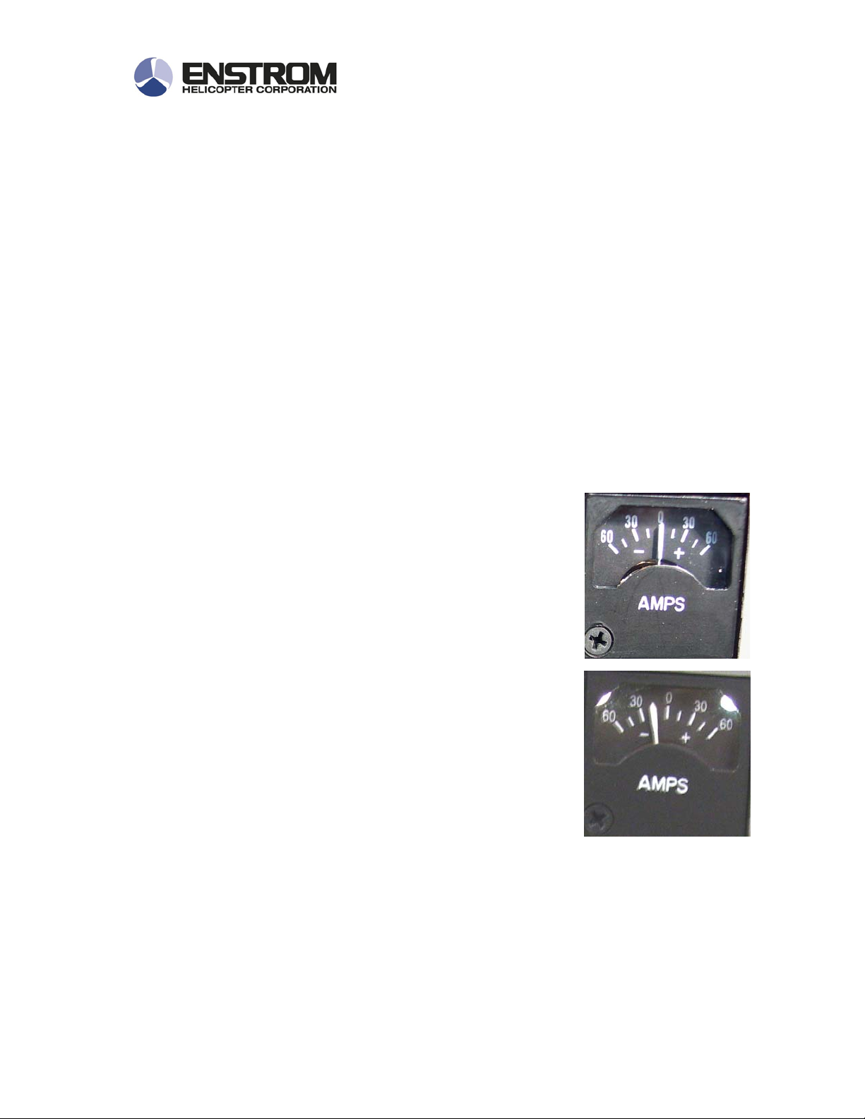
On the Enstrom helicopters, the ammeter measures the
voltage that is going in and out of the battery; it is not a
load meter. After the engine is first started, the ammeter
will indicate a high rate-of-charge until the battery charge is
replenished. As the battery becomes charged, the rate-ofcharge indicated by the ammeter will drop off slowly until it
reads only slightly above zero. If the alternator stops
charging, the Alternator segment on the annunciator
panel will light, and the ammeter will indicate negative
amperage equal to the electrical load being used by the
helicopter.
The voltage regulator is sensitive to both over-voltage and
momentary charging interruptions. If the operator notices
the alternator caution light is illuminated, the voltage
regulator may be reset by turning off the alternator switch
for a few seconds and then turning it back on.
Enstrom Helicopter Corporation 23
Post Office Box 490
Menominee, Michigan 49858-0490 U.S.A.
Phone (906) 863-1200

CAUTION AND WARNING SYSTEMS
Description- Caution and warning systems
The annunciator panel is located at the top of the instrument console and
consists of 8 indicator lights with a press-to-test switch at the extreme left.
Pressing this switch will illuminate all of the indicator lights.
The following warning
and precautionary
information is
displayed on the
annunciator panel.
SEGMENT COLOR DESCRIPTION
STARTER
RELAY
RED
Starter is operating
LOW ROTOR
RPM
OVERBOOST AMBER
CLUTCH
ENGAGE
TRGB CHIP AMBER
MRGB CHIP AMBER
LOW FUEL
PRESSURE
LOW VOLTAGE AMBER
Enstrom Helicopter Corporation 24
RED
RED
RED
Post Office Box 490
Menominee, Michigan 49858-0490 U.S.A.
Phone (906) 863-1200
Main rotor RPM is below 334
Manifold pressure is approaching Red Line
Belt Clutch is disengaged
Tail rotor gearbox chip detector has
detected ferrous metal fragments
Main rotor gearbox chip detector has
detected ferrous metal fragments
Electric Boost pump is producing less than
15 PSI
Alternator is off-line

Warning Systems Descriptions
Starter Relay
The starter relay warning light is operated by a circuit connected to the starter
relay. Its purpose is to alert the pilot that the starter is operating or is engaged.
There is a slight possibility that the starter might not disengage after the starter
button is released. Continued operation of the helicopter with the starter
engaged, will cause damage to the starter and the starter ring gear, and result in
the helicopter not starting.
It is also possible that in the event of a starter solenoid failure, the starter might
remain engaged and also the magneto might remain in the retard mode which
would result in a sever reduction of power and rough running engine.
Low Rotor RPM
The Low Rotor RPM circuit consists of a magnetic sensor in the main rotor
gearbox, a signal generator located behind the passenger’s seat back, a light
located in the annunciator panel, and an audio warning horn.
The RPM sensor in the main rotor gearbox is a magnetic pick-up unit that is
installed in the forward section of the gearbox and that senses the ring gear
teeth passing and sends a signal to a relay and control box that are located on a
bulkhead just behind the right passenger seat back.
The sensor reads the signal that comes from the gearbox magnetic pickup and
routes it to the annunciator panel and the audio warning horn. The audio
warning system consists of a horn located in the head liner and a connection with
the helicopter intercom system that broadcasts the horn into the pilots head sets.
Because the low rotor warning system is armed by the clutch-engage switch, the
Low Rotor RPM warning light will only illuminate if the clutch is engaged. There
is also a switch on the collective system that disengages the Low Rotor RPM
warning system when the collective is in the full down position.
After the engine is started, the following sequences will occur in the Low Rotor
RPM warning system. The red Clutch Engage light will be on until the clutch is
engaged. When the clutch handle snaps into position, the red Clutch Engage
light will go out, and the red Low Rotor light will illuminate.
Enstrom Helicopter Corporation 25
Post Office Box 490
Menominee, Michigan 49858-0490 U.S.A.
Phone (906) 863-1200

The Low Rotor RPM warning light will remain on until the Rotor RPM exceeds
334, but the horn will not sound unless the collective is raised off the bottom stop
and the RPM is less than 334 RPM.
The Low Rotor RPM warning light and horn will activate anytime the clutch is
engaged, the rotor RPM is less than 334, and the collective is raised off of the
down stop.
The RPM that the low rotor RPM system operates at can be adjusted by turning
a potentiometer that is located on the sensor relay that is behind the passenger
seat.
Overboost
The overboost circuit consists of a pressure switch that is installed in the
manifold pressure gauge line and an amber light in the annunciator panel. The
switch is designed to illuminate the light at between 36 and 40 inches of manifold
pressure. The switch and light may be activated by short pressure pulses that
might not register on the manifold pressure gauge. The light is a warning to the
pilot that maximum manifold pressure limits may be exceeded and that the
manifold pressure gauge should be monitored.
The overboost light is intended to be a warning; the manifold pressure gauge
should be used to determine actual manifold pressure.
Clutch Engage
The clutch engage light is activated by a switch that is located on the belt clutch
capsule. It is a normally closed switch that is opened when the clutch overcenter mechanism snaps into place as the belt clutch is engaged. A second
circuit in the same switch is used for the low rotor warning system.
If the Clutch Engage light does not go out when the handle is stowed, or comes
on in flight, a problem with the clutch over-center locking mechanism is indicated.
DO NOT FLY THE AIRCRAFT UNTILL THE FAULT HAS BEEN REPAIRED.
Enstrom Helicopter Corporation 26
Post Office Box 490
Menominee, Michigan 49858-0490 U.S.A.
Phone (906) 863-1200
 Loading...