

Page 1

This electronic document is not linked to a subscription for revision control or distribution. Refer to theTechnical
Publications Status link under the Technical Support Page of the Enstrom Helicopter website for the current revision
level of the 280FX Rotorcraft Flight Manual.
UNCONTROLLED COPY WHEN DOWNLOADED OR PRINTED
ENSTROM 280FX OPERATOR’S MANUAL
Record of Revisions
Revision
Number
Issue
Date
Date
Inserted
1 12/31/80 2/21/12 J. Wingers
2 1/11/85 2/21/12 J. Wingers
3 7/12/85 2/21/12 J. Wingers
4 1/11/91 2/21/12 J. Wingers
5 6/7/07 2/21/12 J. Wingers
6 2/21/12 3/26/12 J. Wingers
7 6/4/12 7/10/12 J. Wingers
8 1/7/13 2/11/13 J. Wingers
9 11/5/13 1/30/14 J. Wingers
10 4/15/15 8/4/15 J. Wingers
By
11 9/20/17 11/2/17 J. Wingers
12 12/3/18 3/13/19 J. Wingers
Maintain this record in the front of the manual.
Page 2

This electronic document is not linked to a subscription for revision control or distribution. Refer to theTechnical
Publications Status link under the Technical Support Page of the Enstrom Helicopter website for the current revision
level of the 280FX Rotorcraft Flight Manual.
UNCONTROLLED COPY WHEN DOWNLOADED OR PRINTED
Page 3

ENSTROM 280FX OPERATOR MANUAL
This electronic document is not linked to a subscription for revision control or distribution. Refer to theTechnical
Publications Status link under the Technical Support Page of the Enstrom Helicopter website for the current revision
level of the 280FX Rotorcraft Flight Manual.
UNCONTROLLED COPY WHEN DOWNLOADED OR PRINTED
AND
FAA APPROVED
ROTORCRAFT FLIGHT MANUAL
* * * * *
REPORT NO. 28-AC-020
TYPE CERTIFICATE NO. H1CE
HELICOPTER SERIAL NO.
HELICOPTER REGISTRATION NO.
* * * * *
THIS MANUAL MUST BE CARRIED IN THE HELICOPTER
AT ALL TIMES. SECTIONS 2, 3, 4, AND 5 ARE FAA
APPROVED. SECTION 10 INCLUDES SUPPLEMENTS TO
THE TYPE CERTIFICATE WHICH ARE FAA APPROVED
IF SO DESIGNATED.
FAA APPROVED BY:
FOR MANAGER
CHICAGO AIRCRAFT CERTIFICATION OFFICE
CENTRAL REGION
FEDERAL AVIATION ADMINISTRATION
FAA APPROVAL DATE:____________________________
THE ENSTROM HELICOPTER CORPORATION
2209 22
MENOMINEE, MICHIGAN 49858-3515
ND
STREET
Rev. 6
Feb 21/12
Page 4

This electronic document is not linked to a subscription for revision control or distribution. Refer to theTechnical
Publications Status link under the Technical Support Page of the Enstrom Helicopter website for the current revision
level of the 280FX Rotorcraft Flight Manual.
UNCONTROLLED COPY WHEN DOWNLOADED OR PRINTED
INTENTIONALLY LEFT BLANK
Page 5
ENSTROM 280FX OPERATOR’S MANUAL i
This electronic document is not linked to a subscription for revision control or distribution. Refer to theTechnical
Publications Status link under the Technical Support Page of the Enstrom Helicopter website for the current revision
level of the 280FX Rotorcraft Flight Manual.
UNCONTROLLED COPY WHEN DOWNLOADED OR PRINTED
LOG OF REVISIONS
Rev.
No.
Date FAA Approved
1 Jul 12/85 G. Louser
2 Dec 14/88 P. Moe
3 May 22/89 P. Moe
4 Jan 11/91 R. Adler
5 Jun 8/07 J. Miess
6 Mar 26/12 S. Lardinois
7 Jul 9/12 J. Miess
8 Feb 11/13 J. Miess
9 Nov 26/13 R. D. McElroy
10 Jul 27/15 R. D. McElroy
11 Oct 25/17 E. Kinney
12
D. Barbini
FAA Approved by
Manager, Southwest Flight Test Section, AIR-713
Federal Aviation Administration
Ft. Worth, TX
NOTE
All revisions are indicated by a black
vertical line.
Rev. 12
Report No. 28-AC-020 Dec 3/18
Page 6

ii ENSTROM 280FX OPERATOR’S MANUAL
This electronic document is not linked to a subscription for revision control or distribution. Refer to theTechnical
Publications Status link under the Technical Support Page of the Enstrom Helicopter website for the current revision
level of the 280FX Rotorcraft Flight Manual.
UNCONTROLLED COPY WHEN DOWNLOADED OR PRINTED
EASA LOG OF REVISIONS
Rev.
No.
1
2
3
4
5 Jul 4/14 EASA 10049746 N/A
6 Jun 9/15 EASA 10053596 N/A
7 Jul 9/15 FAA/EASA T.I.P* G. J. Michalik
8 Jun 9/15 EASA 10053594 N/A
9 Jul 9/15 FAA/EASA T.I.P* G. J. Michalik
10
Date EASA Approved
Sep
28/03
Sep
28/03
Sep
28/03
Sep
28/03
Feb
13/17
Article 3, Commission
Regulation (EU)
748/2012
Article 3, Commission
Regulation (EU)
748/2012
Article 3, Commission
Regulation (EU)
748/2012
Article 3, Commission
Regulation (EU)
748/2012
FAA/EASA T.I.P* G. J. Michalik
FAA Approval
on Behalf of
EASA
N/A
N/A
N/A
N/A
11 Apr 5/18 FAA/EASA T.I.P* M. Runyan
* Section 3.2 T.I.P.
Rev. 12
Report No. 28-AC-020 Dec 3/18
Page 7

ENSTROM 280FX OPERATOR’S MANUAL iii
This electronic document is not linked to a subscription for revision control or distribution. Refer to theTechnical
Publications Status link under the Technical Support Page of the Enstrom Helicopter website for the current revision
level of the 280FX Rotorcraft Flight Manual.
UNCONTROLLED COPY WHEN DOWNLOADED OR PRINTED
LOG OF SUPPLEMENTS
Supplement
No.
1
2
Description Date FAA Approved
Wet/Dry
Dispersal System
Float Landing
Gear
Jan 11/91 R. Adler
Jul 12/85 G. Louser
3 External Loads Jan 11/85 G. Louser
4 Snowshoe May 22/89 P. Moe
5 Reserved
6 Reserved
7 Reserved
8 Reserved
9 Reserved
10 Reserved
11
12
Auxiliary Fuel
Tank
Engine Exhaust
Muffler
Jan 11/85 G. Louser
Jul 16/86 P. Moe
APPROVED FOR THE MANAGER
CHICAGO AIRCRAFT CERTIFICATION OFFICE
CENTRAL REGION
FEDERAL AVIATION ADMINISTRATION
Rev. 6
Report No. 28-AC-020 Feb 21/12
Page 8

iv ENSTROM 280FX OPERATOR’S MANUAL
This electronic document is not linked to a subscription for revision control or distribution. Refer to theTechnical
Publications Status link under the Technical Support Page of the Enstrom Helicopter website for the current revision
level of the 280FX Rotorcraft Flight Manual.
UNCONTROLLED COPY WHEN DOWNLOADED OR PRINTED
EASA LOG OF SUPPLEMENTS
Sup.
No.
Description Date EASA Approved
Approval
on Behalf
of EASA
Wet/Dry
1
Dispersal
System
Float Landing
2
Gear
External
3
Loads
4 Snowshoe
Sep
28/03
Sep
28/03
Sep
28/03
Sep
28/03
5 Reserved
6 Reserved
Article 3, Commission
Regulation (EU)
748/2012
Article 3, Commission
Regulation (EU)
748/2012
Article 3, Commission
Regulation (EU)
748/2012
Article 3, Commission
Regulation (EU)
748/2012
FAA
N/A
N/A
N/A
N/A
7 Reserved
8 Reserved
9 Reserved
10 Reserved
11
12
Auxiliary
Fuel Tank
Engine
Exhaust
Muffler
Sep
28/03
Sep
28/03
Article 3, Commission
Regulation (EU)
Article 3, Commission
Regulation (EU)
748/2012
748/2012
Rev. 11
Report No. 28-AC-020 Sep 20/17
N/A
N/A
Page 9

ENSTROM 280FX OPERATOR’S MANUAL v
This electronic document is not linked to a subscription for revision control or distribution. Refer to theTechnical
Publications Status link under the Technical Support Page of the Enstrom Helicopter website for the current revision
level of the 280FX Rotorcraft Flight Manual.
UNCONTROLLED COPY WHEN DOWNLOADED OR PRINTED
TABLE OF CONTENTS
SECTION DESCRIPTION PAGE
Manual Cover
Log of Revisions ..........................................i
EASA Log of Revisions ............................... ii
Log of Supplements .................................. iii
EASA Log of Supplements ......................... iv
Table of Contents....................................... v
List of Effective Pages ............................. vii
1 GENERAL .............................................. 1-1
2 OPERATING LIMITATIONS ..................... 2-1
3 EMERGENCY PROCEDURES ................ 3-1
4 NORMAL PROCEDURES ........................ 4-1
5 PERFORMANCE .................................... 5-1
6 WEIGHT/BALANCE AND LOADING ....... 6-1
7 AIRCRAFT AND SYSTEM
DESCRIPTION ....................................... 7-1
8 HANDLING, SERVICING, AND
MAINTENANCE ..................................... 8-1
9 OPERATIONAL INFORMATION .............. 9-1
10 OPTIONAL EQUIPMENT
SUPPLEMENTS ................................ 10-0-1
10-1 SUPPLEMENT 1
Wet/Dry Dispersal System ............... 10-1-1
10-2 SUPPLEMENT 2
Float Landing Gear ........................... 10-2-1
10-3 SUPPLEMENT 3
External Loads ................................. 10-3-1
10-4 SUPPLEMENT 4
Snowshoe ......................................... 10-4-1
Rev. 6
Report No. 28-AC-020 Feb 21/12
Page 10

vi ENSTROM 280FX OPERATOR’S MANUAL
This electronic document is not linked to a subscription for revision control or distribution. Refer to theTechnical
Publications Status link under the Technical Support Page of the Enstrom Helicopter website for the current revision
level of the 280FX Rotorcraft Flight Manual.
UNCONTROLLED COPY WHEN DOWNLOADED OR PRINTED
TABLE OF CONTENTS
SECTION DESCRIPTION PAGE
OPTIONAL EQUIPMENT
SUPPLEMENTS - Continued
10-5 SUPPLEMENT 5
(Reserved) .......................................... 10-5-1
10-6 SUPPLEMENT 6
(Reserved) .......................................... 10-6-1
10-7 SUPPLEMENT 7
(Reserved) .......................................... 10-7-1
10-8 SUPPLEMENT 8
(Reserved) .......................................... 10-8-1
10-9 SUPPLEMENT 9
(Reserved) .......................................... 10-9-1
10-10 SUPPLEMENT 10
(Reserved) ....................................... 10-10-1
10-11 SUPPLEMENT 11
Auxiliary Fuel Tank ........................ 10-11-1
10-12 SUPPLEMENT 12
Engine Exhaust Muffler .................. 10-12-1
Rev. 6
Report No. 28-AC-020 Feb 21/12
Page 11

ENSTROM 280FX OPERATOR’S MANUAL vii
This electronic document is not linked to a subscription for revision control or distribution. Refer to theTechnical
Publications Status link under the Technical Support Page of the Enstrom Helicopter website for the current revision
level of the 280FX Rotorcraft Flight Manual.
UNCONTROLLED COPY WHEN DOWNLOADED OR PRINTED
LIST OF EFFECTIVE PAGES
PAGE DATE PAGE DATE
Cover Feb 21/12
i Dec 3/18
ii Dec 3/18
iii Feb 21/12
iv Sep 20/17
v Feb 21/12
vi Feb 21/12
vii Dec 3/18
viii Dec 3/18
ix Sep 20/17
x Nov 5/13
1-1 Feb 21/12
1-2 Feb 21/12
1-3 Feb 21/12
1-4 Feb 21/12
1-5 Feb 21/12
1-6 Feb 21/12
1-7 Feb 21/12
1-8 Feb 21/12
2-1 Feb 21/12
2-2 Feb 21/12
2-3 Feb 21/12
2-4 Feb 21/12
2-5 Feb 21/12
2-6 Feb 21/12
2-7 Dec 3/18
2-8 Feb 21/12
2-9 Feb 21/12
2-10 Feb 21/12
2-11 Feb 21/12
2-12 Feb 21/12
2-13 Feb 21/12
2-14 Feb 21/12
2-15 Feb 21/12
2-16 Feb 21/12
3-1 Nov 5/13
3-2 Nov 5/13
3-3 Nov 5/13
3-4 Nov 5/13
3-5 Nov 5/13
3-6 Nov 5/13
3-7 Nov 5/13
3-8 Nov 5/13
3-9 Nov 5/13
3-10 Nov 5/13
3-11 Nov 5/13
3-12 Nov 5/13
3-13 Nov 5/13
3-14 Nov 5/13
3-15 Nov 5/13
3-16 Nov 5/13
3-17 Nov 5/13
3-18 Nov 5/13
3-19 Nov 5/13
3-20 Nov 5/13
3-21 Nov 5/13
3-22 Nov 5/13
3-23 Nov 5/13
3-24 Nov 5/13
3-25 Nov 5/13
3-26 Nov 5/13
4-1 Feb 21/12
4-2 Feb 21/12
4-3 Dec 3/18
4-4 Dec 3/18
4-5 Feb 21/12
4-6 Feb 21/12
4-7 Feb 21/12
4-8 Dec 3/18
4-9 Dec 3/18
4-10 Dec 3/18
4-11 Dec 3/18
4-12 Dec 3/18
4-13 Dec 3/18
4-14 Feb 21/12
4-15 Apr 15/15
4-16 Apr 15/15
4-17 Apr 15/15
4-18 Apr 15/15
4-19 Apr 15/15
Rev. 12
Report No. 28-AC-020 Dec 3/18
Page 12

viii ENSTROM 280FX OPERATOR’S MANUAL
This electronic document is not linked to a subscription for revision control or distribution. Refer to theTechnical
Publications Status link under the Technical Support Page of the Enstrom Helicopter website for the current revision
level of the 280FX Rotorcraft Flight Manual.
UNCONTROLLED COPY WHEN DOWNLOADED OR PRINTED
LIST OF EFFECTIVE PAGES
PAGE DATE PAGE DATE
4-20 Apr 15/15
4-21 Nov 5/13
4-22 Feb 21/12
4-23 Feb 21/12
4-24 Feb 21/12
5-1 Feb 21/12
5-2 Feb 21/12
5-3 Feb 21/12
5-4 Feb 21/12
5-5 Feb 21/12
5-6 Feb 21/12
5-7 Feb 21/12
5-8 Feb 21/12
5-9 Feb 21/12
5-10 Feb 21/12
5-11 Feb 21/12
5-12 Feb 21/12
6-1 Sep 20/17
6-2 Feb 21/12
6-3 Sep 20/17
6-4 Sep 20/17
6-5 Sep 20/17
6-6 Feb 21/12
6-7 Sep 20/17
6-8 Sep 20/17
6-9 Dec 3/18
6-10 Sep 20/17
6-11 Sep 20/17
6-12 Sep 20/17
6-13 Sep 20/17
6-14 Sep 20/17
6-15 Sep 20/17
6-16 Sep 20/17
7-1 Sep 20/17
7-2 Feb 21/12
7-3 Feb 21/12
7-4 Apr 15/15
7-5 Apr 15/15
7-6 Nov 5/13
7-7 Nov 5/13
7-8 Nov 5/13
7-9 Nov 5/13
7-10 Nov 5/13
7-11 Dec 3/18
7-12 Dec 3/18
7-13 Dec 3/18
7-14 Dec 3/18
7-15 Dec 3/18
7-16 Dec 3/18
7-17 Sep 20/17
7-18 Nov 5/13
8-1 Feb 21/12
8-2 Feb 21/12
8-3 Feb 21/12
8-4 Feb 21/12
8-5 Feb 21/12
8-6 Feb 21/12
8-7 Feb 21/12
8-8 Feb 21/12
8-9 Feb 21/12
8-10 Feb 21/12
8-11 Feb 21/12
8-12 Sep 20/17
8-13 Nov 5/13
8-14 Sep 20/17
8-15 Sep 20/17
8-16 Feb 21/12
8-17 Feb 21/12
8-18 Sep 20/17
8-19 Feb 21/12
8-20 Feb 21/12
8-21 Sep 20/17
8-22 Feb 21/12
8-23 Feb 21/12
8-24 Feb 21/12
9-1 Feb 21/12
9-2 Feb 21/12
10-0-1 Feb 21/12
10-0-2 Feb 21/12
10-1-1 Feb 21/12
Rev. 12
Report No. 28-AC-020 Dec 3/18
Page 13

ENSTROM 280FX OPERATOR’S MANUAL ix
This electronic document is not linked to a subscription for revision control or distribution. Refer to theTechnical
Publications Status link under the Technical Support Page of the Enstrom Helicopter website for the current revision
level of the 280FX Rotorcraft Flight Manual.
UNCONTROLLED COPY WHEN DOWNLOADED OR PRINTED
LIST OF EFFECTIVE PAGES
PAGE DATE PAGE DATE
10-1-2 Feb 21/12
10-1-3 Feb 21/12
10-1-4 Feb 21/12
10-1-5 Feb 21/12
10-1-6 Feb 21/12
10-1-7 Feb 21/12
10-1-8 Feb 21/12
10-1-9 Feb 21/12
10-1-10 Feb 21/12
10-1-11 Feb 21/12
10-1-12 Feb 21/12
10-1-13 Feb 21/12
10-1-14 Feb 21/12
10-1-15 Sep 20/17
10-1-16 Feb 21/12
10-1-17 Feb 21/12
10-1-18 Feb 21/12
10-1-19 Feb 21/12
10-1-20 Feb 21/12
10-2-1 Feb 21/12
10-2-2 Feb 21/12
10-2-3 Feb 21/12
10-2-4 Feb 21/12
10-2-5 Feb 21/12
10-2-6 Feb 21/12
10-2-7 Feb 21/12
10-2-8 Feb 21/12
10-2-9 Feb 21/12
10-2-10 Feb 21/12
10-2-11 Feb 21/12
10-2-12 Feb 21/12
10-2-13 Feb 21/12
10-2-14 Feb 21/12
10-2-15 Feb 21/12
10-2-16 Feb 21/12
10-2-17 Feb 21/12
10-2-18 Feb 21/12
10-3-1 Feb 21/12
10-3-2 Feb 21/12
10-3-3 Feb 21/12
10-3-4 Feb 21/12
10-3-5 Feb 21/12
10-3-6 Feb 21/12
10-3-7 Feb 21/12
10-3-8 Feb 21/12
10-3-9 Feb 21/12
10-3-10 Feb 21/12
10-3-11 Feb 21/12
10-3-12 Feb 21/12
10-4-1 Feb 21/12
10-4-2 Feb 21/12
10-4-3 Feb 21/12
10-4-4 Feb 21/12
10-5-1 Feb 21/12
10-5-2 Feb 21/12
10-6-1 Feb 21/12
10-6-2 Feb 21/12
10-7-1 Feb 21/12
10-7-2 Feb 21/12
10-8-1 Feb 21/12
10-8-2 Feb 21/12
10-9-1 Feb 21/12
10-9-2 Feb 21/12
10-10-1 Feb 21/12
10-10-2 Feb 21/12
10-11-1 Feb 21/12
10-11-2 Feb 21/12
10-11-3 Feb 21/12
10-11-4 Feb 21/12
10-11-5 Feb 21/12
10-11-6 Feb 21/12
10-11-7 Feb 21/12
10-11-8 Feb 21/12
10-11-9 Feb 21/12
10-11-10 Feb 21/12
10-11-11 Feb 21/12
10-11-12 Feb 21/12
10-11-13 Feb 21/12
10-11-14 Feb 21/12
10-12-1 Jan 7/13
Rev. 11
Report No. 28-AC-020 Sep 20/17
Page 14

x ENSTROM 280FX OPERATOR’S MANUAL
This electronic document is not linked to a subscription for revision control or distribution. Refer to theTechnical
Publications Status link under the Technical Support Page of the Enstrom Helicopter website for the current revision
level of the 280FX Rotorcraft Flight Manual.
UNCONTROLLED COPY WHEN DOWNLOADED OR PRINTED
LIST OF EFFECTIVE PAGES
PAGE DATE PAGE DATE
10-12-2 Feb 21/12
10-12-3 Feb 21/12
10-12-4 Feb 21/12
Rev. 9
Report No. 28-AC-020 Nov 5/13
Page 15

ENSTROM 280FX OPERATOR’S MANUAL 1-1
This electronic document is not linked to a subscription for revision control or distribution. Refer to theTechnical
Publications Status link under the Technical Support Page of the Enstrom Helicopter website for the current revision
level of the 280FX Rotorcraft Flight Manual.
UNCONTROLLED COPY WHEN DOWNLOADED OR PRINTED
SECTION 1. GENERAL
TABLE OF CONTENTS
PARAGRAPH DESCRIPTION PAGE
Table of Contents ................................ 1-1
1-1 Introduction ....................................... 1-3
1-2 Owner Responsibilities........................ 1-3
1-3 Pilot Responsibilities ........................... 1-4
1-4 Warnings, Cautions, and Notes ........... 1-4
1-5 Specifications ..................................... 1-5
1-6 Performance ....................................... 1-8
LIST OF FIGURES
FIGURE NO. DESCRIPTION PAGE
1-1 Enstrom 280FX .................................. 1-6
Rev. 6
Report No. 28-AC-020 Feb 21/12
Page 16

1-2 ENSTROM 280FX OPERATOR’S MANUAL
This electronic document is not linked to a subscription for revision control or distribution. Refer to theTechnical
Publications Status link under the Technical Support Page of the Enstrom Helicopter website for the current revision
level of the 280FX Rotorcraft Flight Manual.
UNCONTROLLED COPY WHEN DOWNLOADED OR PRINTED
INTENTIONALLY LEFT BLANK
Rev. 6
Report No. 28-AC-020 Feb 21/12
Page 17

ENSTROM 280FX OPERATOR’S MANUAL 1-3
This electronic document is not linked to a subscription for revision control or distribution. Refer to theTechnical
Publications Status link under the Technical Support Page of the Enstrom Helicopter website for the current revision
level of the 280FX Rotorcraft Flight Manual.
UNCONTROLLED COPY WHEN DOWNLOADED OR PRINTED
SECTION 1. GENERAL
1-1. Introduction
This manual contains the operating instructions,
procedures, and limitations for the Enstrom 280FX
helicopter. The manual is divided into two basic parts, the
FAA approved Rotorcraft Flight Manual (RFM) and the
Supplemental Data provided by Enstrom Helicopter
Corporation. Sections 2 through 5 and portions of Section
10 so designated make up the FAA approved RFM. It is
required by Federal Regulations that this manual be carried
in the helicopter at all times.
1-2. Owner Responsibilities
Maintaining the helicopter in an airworthy condition is the
responsibility of the owner. (Reference Section 8 for
required inspections.) To aid the owner in this task,
Enstrom Helicopter Corporation has a network of
Distributors, Dealers, and Service Centers. In addition to
this Operator’s Manual, Enstrom Helicopter Corporation
has the following technical publications available for your
helicopter:
1. F-28F/280F Maintenance Manual with 280FX
Supplement
2. F-28/280 Series Illustrated Parts Catalog
3. Service Information Letters
4. Service Directive Bulletins
Information regarding dealer and service center locations,
technical publications and revisions can be obtained by
contacting:
Enstrom Helicopter Corporation
Attn: Product Support
nd
2209 22
Rev. 6
Report No. 28-AC-020 Feb 21/12
Page 18

1-4 ENSTROM 280FX OPERATOR’S MANUAL
This electronic document is not linked to a subscription for revision control or distribution. Refer to theTechnical
Publications Status link under the Technical Support Page of the Enstrom Helicopter website for the current revision
level of the 280FX Rotorcraft Flight Manual.
UNCONTROLLED COPY WHEN DOWNLOADED OR PRINTED
1-3. Pilot Responsibilities
The pilot is responsible for determining that the helicopter
is safe for flight and is responsible for operating within the
limitations specified in Section 2. The pilot should
familiarize himself with the entire manual prior to receiving
competent flight instruction.
1-4. Warnings, Cautions, and Notes
The use of WARNING, CAUTION, and NOTE to emphasize
important and critical instructions is defined by the
following.
1.
WARNING
An operating practice or procedure, which, if not
correctly followed, could result in personal injury
or loss of life.
2.
CAUTION
An operating practice or procedure, which, if not
correctly followed, could result in damage to, or
destruction of, equipment.
3.
NOTE
An operating practice or procedure, which is
essential and requires additional information.
Rev. 6
Report No. 28-AC-020 Feb 21/12
Page 19

ENSTROM 280FX OPERATOR’S MANUAL 1-5
This electronic document is not linked to a subscription for revision control or distribution. Refer to theTechnical
Publications Status link under the Technical Support Page of the Enstrom Helicopter website for the current revision
level of the 280FX Rotorcraft Flight Manual.
UNCONTROLLED COPY WHEN DOWNLOADED OR PRINTED
1-5. Specifications
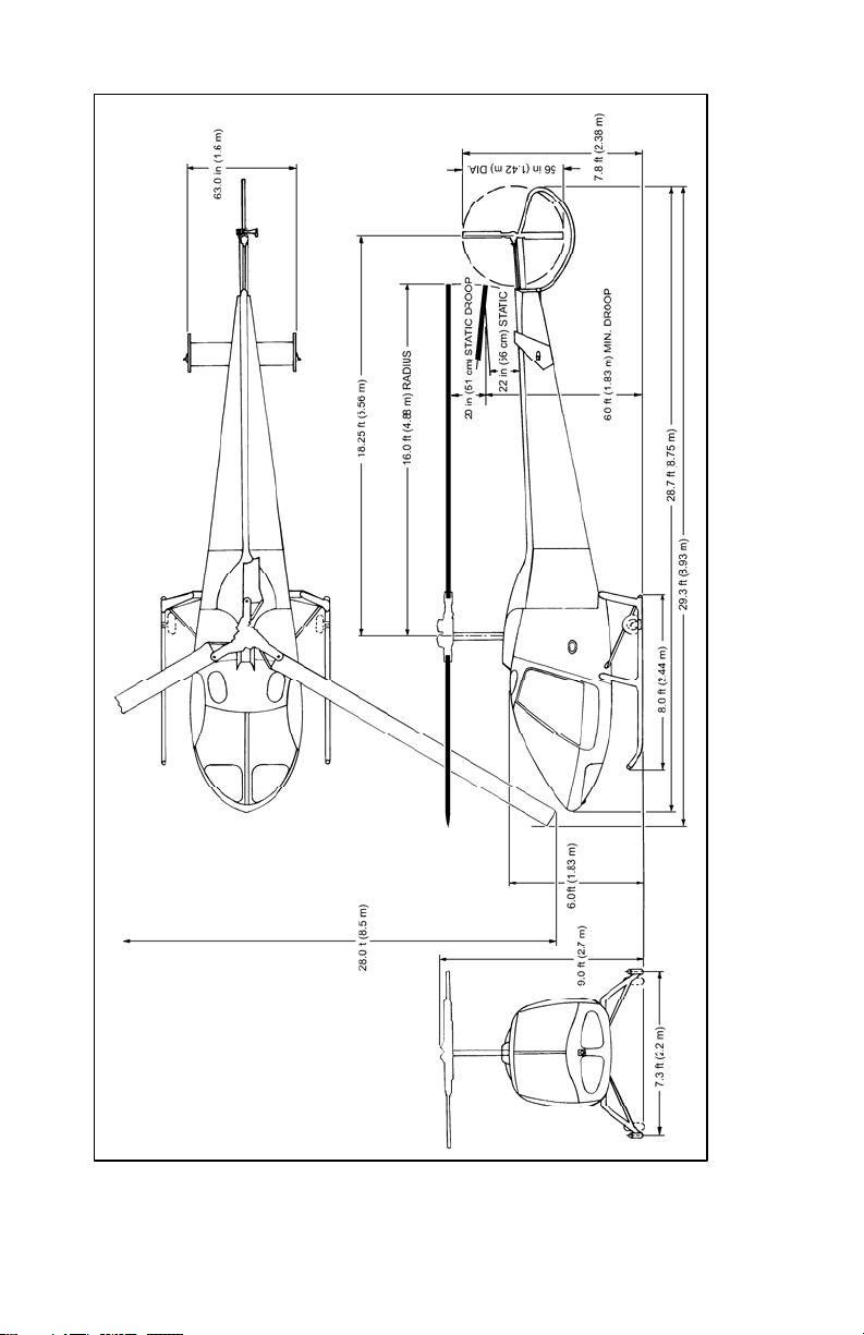
1. Principle dimensions of 280FX helicopters (reference
Figure 1-1).
Width overall 28 ft
Rotor diameter 32 ft
Height overall 9 ft
Length overall
- Blade over tail 29 ft 3 in
- Blade over nose 36 ft 7 in
Cabin width at seat 58 in
Baggage box dimensions 16 in X 18 in X 31 in
Tread – landing gear 7 ft 4 in
2. Power Plant
Type Lycoming
Designation HIO-360-F1AD
Cylinders 4 Opposed
Horsepower 225 hp (sea level to 12,000 ft)
RPM 3050
SFC (full rich) 0.69 lb/hp/hr
Weight 357 lb
Oil 10 qt (8 qt minimum for flight)
NOTE
Total oil capacity for the engine oil system
(including oil lines and coolers) is 10 quarts. The
engine oil sump capacity is 8 quarts. The engine
oil dip stick is marked to correspond with the
engine oil sump capacity of 8 quarts (full) and 6
quarts (low).
Rev. 6
Report No. 28-AC-020 Feb 21/12
Page 20
1-6 ENSTROM 280FX OPERATOR’S MANUAL
This electronic document is not linked to a subscription for revision control or distribution. Refer to theTechnical
Publications Status link under the Technical Support Page of the Enstrom Helicopter website for the current revision
level of the 280FX Rotorcraft Flight Manual.
UNCONTROLLED COPY WHEN DOWNLOADED OR PRINTED
Figure 1-1. Enstrom 280FX
Rev. 6
Report No. 28-AC-020 Feb 21/12
Page 21

ENSTROM 280FX OPERATOR’S MANUAL 1-7
This electronic document is not linked to a subscription for revision control or distribution. Refer to theTechnical
Publications Status link under the Technical Support Page of the Enstrom Helicopter website for the current revision
level of the 280FX Rotorcraft Flight Manual.
UNCONTROLLED COPY WHEN DOWNLOADED OR PRINTED
3. Ratios
Lower drive pulley to
upper pulley
Upper pulley to main
rotor shaft
Engine to main rotor 8.678:1 (3050-351 RPM)
Tail rotor input shaft
to output shaft
4. Rotor Systems
Number of blades, main rotor 3
Chord, main rotor blade 9.5 in
Disk area, main rotor 804 sq ft
Number of blades, tail rotor 2
Chord, tail rotor blade 4.4 in
Disk area, tail rotor 17.1 sq ft
5. Weight
Designed gross weight 2600 lb
Empty weight 1570 lb
Useful load 1030 lb
C.G. travel 96.3 to 98.0 inches at 2600 lb
1.213:1 (3050-2514 RPM)
7.154:1 (2514-351 RPM)
1:1
92.0 to 98.8 inches at 2350 lb
92.0 to 100.0 inches at 2000 lb
NOTE
Four gross weight/c.g. envelopes apply to this
helicopter (reference Figure 6-1). Each envelope
is associated with a different maximum ceiling
and a different V
limitation (reference Figure 5-
NE
1).
Rev. 6
Report No. 28-AC-020 Feb 21/12
Page 22

1-8 ENSTROM 280FX OPERATOR’S MANUAL
This electronic document is not linked to a subscription for revision control or distribution. Refer to theTechnical
Publications Status link under the Technical Support Page of the Enstrom Helicopter website for the current revision
level of the 280FX Rotorcraft Flight Manual.
UNCONTROLLED COPY WHEN DOWNLOADED OR PRINTED
1-6. Performance1
1. Maximum
speed
V
NE
Power On
VNE
Power Off
117 MPH IAS from sea level
1
to 3000 ft DA
(Reference Figure 5-1)
85 MPH IAS from sea level to
8200 ft DA
(Reference Figure 5-1)
NOTE
Four different maximum ceiling/V
envelopes
NE
apply to this helicopter (reference Figure 5-1).
Each envelope corresponds to a gross weight/
c.g. envelope (reference Figure 6-1).
2. Cruise speed
110 MPH IAS at sea level
75% power
3. Maximum cruise speed 117 MPH TAS at sea level
122 MPH TAS at 3000 ft H
4. Maximum range speed 85 MPH IAS at sea level
5. Fuel consumption
14.7 gal/hr
75% power, leaned
6. Maximum endurance, no
3.5 hr
reserve 57 MPH IAS at
sea level, leaned
7. Fuel capacity 42 gal (40 gal usable)
8. Maximum R/C at sea
1450 ft/min
level
9. Hover ceiling IGE 13,600 ft
(See Item 11)
10. Hover ceiling OGE 8700 ft
11. Maximum approved
operating altitude
12,000 ft
(Reference Figure 5-1)
d
1
All altitudes are density altitude (DA) and performance based on
a 2350 lb gross weight unless otherwise noted.
Rev. 6
Report No. 28-AC-020 Feb 21/12
Page 23

ENSTROM 280FX OPERATOR’S MANUAL 2-1
This electronic document is not linked to a subscription for revision control or distribution. Refer to theTechnical
Publications Status link under the Technical Support Page of the Enstrom Helicopter website for the current revision
level of the 280FX Rotorcraft Flight Manual.
UNCONTROLLED COPY WHEN DOWNLOADED OR PRINTED
SECTION 2. OPERATING LIMITATIONS
TABLE OF CONTENTS
PARAGRAPH DESCRIPTION PAGE
Table of Contents ................................ 2-1
2-1 Type of Operation ............................... 2-3
2-2 Weight ................................................ 2-3
2-3 Center of Gravity ................................ 2-3
2-4 Airspeed ............................................. 2-5
2-5 Altitude ............................................... 2-5
2-6 Rotor RPM .......................................... 2-6
2-7 Power Plant Limitations ...................... 2-7
2-8 Transmission Limitations ................... 2-8
2-9 Restrictions ........................................ 2-8
2-10 Minimum Crew ................................... 2-8
2-11 Instrument Markings .......................... 2-8
2-12 Placards............................................ 2-10
LIST OF FIGURES
FIGURE NO. DESCRIPTION PAGE
2-1 VNE Placard – Envelopes A & B .......... 2-11
2-2 V
2-3 V
Placard – Envelopes C & D ......... 2-12
NE
Placard – Envelopes A & B
NE
(w/120°F) ......................................... 2-13
2-4 V
Placard – Envelopes C & D
NE
(w/120°F) ......................................... 2-14
FAA Approved: Mar 26/12 Rev. 6
Report No. 28-AC-020 Feb 21/12
Page 24

2-2 ENSTROM 280FX OPERATOR’S MANUAL
This electronic document is not linked to a subscription for revision control or distribution. Refer to theTechnical
Publications Status link under the Technical Support Page of the Enstrom Helicopter website for the current revision
level of the 280FX Rotorcraft Flight Manual.
UNCONTROLLED COPY WHEN DOWNLOADED OR PRINTED
INTENTIONALLY LEFT BLANK
FAA Approved: Mar 26/12 Rev. 6
Report No. 28-AC-020 Feb 21/12
Page 25

ENSTROM 280FX OPERATOR’S MANUAL 2-3
This electronic document is not linked to a subscription for revision control or distribution. Refer to theTechnical
Publications Status link under the Technical Support Page of the Enstrom Helicopter website for the current revision
level of the 280FX Rotorcraft Flight Manual.
UNCONTROLLED COPY WHEN DOWNLOADED OR PRINTED
SECTION 2. OPERATING LIMITATIONS
2-1. Type of Operation
1. This helicopter is approved for operation under day and
night VFR non-icing conditions.
2. Operation with doors removed is approved. All loose
objects and equipment within the cabin must be properly
secured.
NOTE
Refer to Section 6 for proper weight and balance
calculations for operation with the doors removed.
2-2. Weight
1. The maximum gross weight of this helicopter is 2600
pounds (reference Figure 6-1).
2-3. Center of Gravity
NOTE
All airspeeds are IAS unless otherwise noted.
1. The longitudinal datum is 100.0 inches forward of the
center of the main rotor head.
2. There are four gross weight/c.g. envelopes for this
helicopter (reference Figure 6-1). Each envelope
corresponds to one of four V
/altitude envelopes as
NE
described in Paragraph 2-4 (reference Figure 5-1).
3. Envelope A is the lightest weight envelope with a V
117 MPH at sea level. The c.g. and gross weight limits vary
as follows:
a. Upper weight limit is 2350 lb.
b. Forward limit is at 92.0 inches.
FAA Approved: Mar 26/12 Rev. 6
Report No. 28-AC-020 Feb 21/12
NE
of
Page 26

2-4 ENSTROM 280FX OPERATOR’S MANUAL
This electronic document is not linked to a subscription for revision control or distribution. Refer to theTechnical
Publications Status link under the Technical Support Page of the Enstrom Helicopter website for the current revision
level of the 280FX Rotorcraft Flight Manual.
UNCONTROLLED COPY WHEN DOWNLOADED OR PRINTED
c. Aft limit varies linearly from 94.6 inches at 2350 lb to
100.0 inches at 2000 lb. Aft limit at 100.0 inches below
2000 lb.
4. Envelope B is the next heavier envelope. It has a V
NE
of
104 MPH. The c.g. and gross weight limits vary as follows:
a. Upper weight limit is 2450 lb.
b. Forward limit varies linearly from 93.8 inches at 2450
lb to 92.0 inches at 2350 lb.
c. Aft limit varies linearly from 96.0 inches at 2450 lb to
99.2 inches at 2240 lb and 100.0 inches at 2000 lb.
d. The lower limit corresponds to the upper and aft limits
of Envelope A.
5. Envelope C has a V
at sea level of 91 MPH. The c.g. and
NE
gross weight limits vary as follows:
a. Upper weight limit is 2550 lb.
b. Forward limit varies linearly from 95.5 inches at 2550
lb to 93.8 inches at 2450 lb.
c. Aft limit varies linearly from 97.3 inches at 2550 lb to
98.4 inches at 2470 lb and then to 99.2 inches at 2240
lb.
d. The lower limit corresponds to the upper and aft limits
of Envelope B.
6. Envelope D is the heaviest envelope. It has a V
NE
level of 85 MPH. The c.g. and gross weight limits vary as
follows:
a. Upper weight limit is 2600 lb.
b. Forward limit varies linearly from 96.3 inches at 2600
lb to 95.5 inches at 2550 lb.
c. Aft limit varies linearly from 98.0 inches at 2600 lb to
98.4 inches at 2470 lb.
d. The lower limit corresponds to the upper and aft limits
of Envelope C.
FAA Approved: Mar 26/12 Rev. 6
Report No. 28-AC-020 Feb 21/12
at sea
Page 27

ENSTROM 280FX OPERATOR’S MANUAL 2-5
This electronic document is not linked to a subscription for revision control or distribution. Refer to theTechnical
Publications Status link under the Technical Support Page of the Enstrom Helicopter website for the current revision
level of the 280FX Rotorcraft Flight Manual.
UNCONTROLLED COPY WHEN DOWNLOADED OR PRINTED
7. The lateral datum line is the centerline of the helicopter.
Lateral moment arms are positive right and negative left.
8. Lateral offset moment limits vary with weight (reference
Figure 6-2).
a. From 2025 lb to 2600 lb, limits are -3250 in-lb and
+3700 in-lb.
b. Below 2025 lb, reference Figure 6-2.
2-4. Airspeed
Power-on never exceed speed (V
) is 117 MPH, IAS, sea level
NE
to 3000 ft density altitude. Reference Figure 5-1 for
variations above 3000 ft and for variations with gross
weight/c.g. V
, whichever is lower.
V
NE
for autorotation is 85 MPH or the power-on
NE
NOTE
There are four V
/altitude envelopes that apply to
NE
this helicopter. Each envelope corresponds to one of
four gross weight /c.g. envelopes (reference Figure 5-
1).
2-5. Altitude
Maximum approved operating altitude is 12,000 ft density
altitude at 2350 lb. For variations of altitude with gross
weight, reference Figure 5-1.
NOTE
Takeoffs and landings at 2600 lb gross weight were
demonstrated to 7000 ft density altitude in all wind
conditions up to 20 MPH. DO NOT EXCEED ENGINE
LIMITATIONS.
FAA Approved: Mar 26/12 Rev. 6
Report No. 28-AC-020 Feb 21/12
Page 28

2-6 ENSTROM 280FX OPERATOR’S MANUAL
This electronic document is not linked to a subscription for revision control or distribution. Refer to theTechnical
Publications Status link under the Technical Support Page of the Enstrom Helicopter website for the current revision
level of the 280FX Rotorcraft Flight Manual.
UNCONTROLLED COPY WHEN DOWNLOADED OR PRINTED
NOTE
Takeoffs and landings at 2350 lb gross weight were
demonstrated to 10,000 ft density altitude in all
wind conditions up to 15 MPH.
NOTE
Operators should use appropriate caution above
10,000 ft density altitude and in winds greater than
15 MPH to ensure safe takeoffs and landings.
2-6. Rotor RPM
1. Flight limitations power on:
Minimum 334 RPM
Maximum 351 RPM
2. Flight limitations power off:
Minimum 334 RPM
Maximum 385 RPM
3. Reference Section 8 for adjustment procedures.
NOTE
During transient maneuvers, such as simulated
power failure during pilot training, the rotor RPM
may fall below 334. These maneuvers have been
demonstrated with rotor RPM dropping briefly to
280; however, sufficient time and altitude must be
available to regain RPM.
NOTE
The helicopter is equipped with a rotor RPM warning
device. Operating the helicopter below 334 RPM with
the collective off the down stop will automatically
activate a warning horn.
FAA Approved: Mar 26/12 Rev. 6
Report No. 28-AC-020 Feb 21/12
Page 29

ENSTROM 280FX OPERATOR’S MANUAL 2-7
This electronic document is not linked to a subscription for revision control or distribution. Refer to theTechnical
Publications Status link under the Technical Support Page of the Enstrom Helicopter website for the current revision
level of the 280FX Rotorcraft Flight Manual.
UNCONTROLLED COPY WHEN DOWNLOADED OR PRINTED
2-7. Power Plant Limitations – Lycoming HIO-360-
F1AD with Turbocharger
(Turbocharger installation per STC SE484GL).
1. Maximum continuous
power
2. Engine operating RPM Minimum
225 hp, 3050 RPM, 39.0 in
MP, sea level to 12,000 ft
2900 RPM
Maximum 3050 RPM
3. Engine idle RPM
(clutch disengaged)
4. Manifold pressure
Minimum
1450 RPM
Maximum 1500 RPM
39.0 in Hg maximum, sea
level to 12,000 ft
5. Cylinder head
500°F maximum
temperature
6. EGT/TIT 1650°F maximum
NOTE
The maximum limit for the turbocharger turbine
inlet temperature (TIT) is 1650°F. This limit was
previously referred to as EGT (exhaust gas
temperature).
7. Fuel
100/130 aviation grade
gasoline (green)
100LL aviation grade
gasoline (blue)
8. Fuel
mixture
setting
29 in MP or
below
Maximum fuel flow
- full rich
Minimum fuel flow
- leaned to 1650°F rich side
of peak
29 in MP to
Full rich
39.0 in MP
9. Oil temperature 245°F maximum
10. Oil
pressure
Maximum starting and
warm-up
100 psi
Normal operating 60-90 psi
Minimum idling 25 psi
FAA Approved: Mar 12/19 Rev. 12
Report No. 28-AC-020 Dec 3/18
Page 30

2-8 ENSTROM 280FX OPERATOR’S MANUAL
This electronic document is not linked to a subscription for revision control or distribution. Refer to theTechnical
Publications Status link under the Technical Support Page of the Enstrom Helicopter website for the current revision
level of the 280FX Rotorcraft Flight Manual.
UNCONTROLLED COPY WHEN DOWNLOADED OR PRINTED
2-8. Transmissions Limitations
1. Transmission oil temperature
Maximum 225°F
2-9. Restrictions
1. Instrument flight is prohibited.
2. Aerobatic maneuvers are prohibited.
3. Hovering IGE above 10,000 ft density altitude is limited to
five minutes.
2-10. Minimum Crew
1. One pilot.
2. Solo from left seat only.
2-11. Instrument Markings
1. Rotor tachometer
334 RPM red line
334-385 RPM green arc
385 RPM red line
2. Engine tachometer
2900 RPM red line
2900-3050 RPM green arc
3050 RPM red line
3. Maximum airspeed
85 MPH
(Power off)
117 MPH
blue line or red
cross-hatched line
red line
(Power on)
FAA Approved: Mar 26/12 Rev. 6
Report No. 28-AC-020 Feb 21/12
Page 31

ENSTROM 280FX OPERATOR’S MANUAL 2-9
This electronic document is not linked to a subscription for revision control or distribution. Refer to theTechnical
Publications Status link under the Technical Support Page of the Enstrom Helicopter website for the current revision
level of the 280FX Rotorcraft Flight Manual.
UNCONTROLLED COPY WHEN DOWNLOADED OR PRINTED
4. Manifold pressure
10 in to 39 in Hg green arc
39.0 in Hg red line
Overboost light illuminates at approximately
39 in manifold pressure.
5. Engine oil temperature
245°F red line
120°-245°F green arc
60°-120°F yellow arc
6. Engine oil pressure
100 psi red line
60-100 psi green arc
25-60 psi yellow arc
25 psi red line
7. Cylinder head temperature
500°F red line
200°-500°F green arc
8. Exhaust gas temperature/Turbine inlet temperature
1650°F Maximum
(digital readout with placard)
9. Transmission oil temperature
225°F red line
0°-225°F green arc
FAA Approved: Mar 26/12 Rev. 6
Report No. 28-AC-020 Feb 21/12
Page 32

2-10 ENSTROM 280FX OPERATOR’S MANUAL
This electronic document is not linked to a subscription for revision control or distribution. Refer to theTechnical
Publications Status link under the Technical Support Page of the Enstrom Helicopter website for the current revision
level of the 280FX Rotorcraft Flight Manual.
UNCONTROLLED COPY WHEN DOWNLOADED OR PRINTED
2-12. Placards
1. Placards that are required to be placed in view of the pilot
are:
a.
THIS HELICOPTER MUST BE OPERATED IN
COMPLIANCE WITH THE OPERATING
LIMITATIONS SPECIFIED IN THE FAA
APPROVED ROTORCRAFT FLIGHT MANUAL
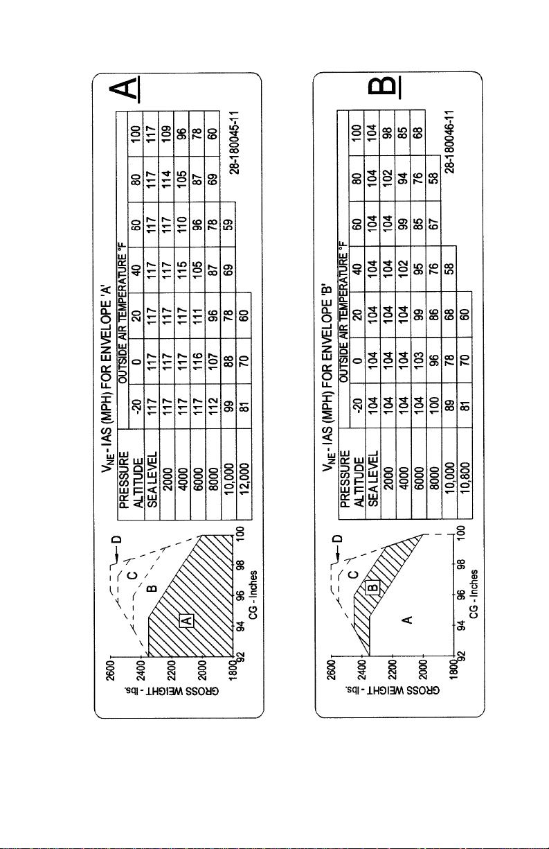
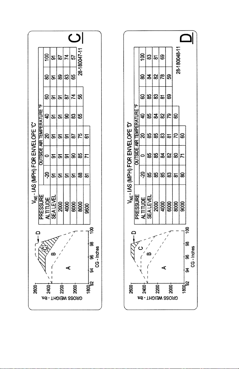
b. Placards for 280FX VNE (located overhead above center
windshield):
(1) V
placards shown in Figure 2-1 and Figure 2-2
NE
are used on all 280FX helicopters serial number
2132 and prior.
(2) V
placards shown in Figure 2-3 and Figure 2-4
NE
are used on all 280FX helicopters serial number
2133 and subsequent. 280FX helicopters serial
number 2132 and prior may also use these
placards.
c. Smoking restrictions – (This placard is not required if
approved ashtray is installed.)
NO SMOKING
d.
THIS HELICOPTER IS APPROVED FOR
OPERATION UNDER DAY AND NIGHT VFR NONICING CONDITIONS ONLY
e. This placard is to be placed adjacent to the collective
friction device.
COLLECTIVE FRICTION TO BE USED FOR
GROUND OPERATION ONLY
FAA Approved: Mar 26/12 Rev. 6
Report No. 28-AC-020 Feb 21/12
Page 33
ENSTROM 280FX OPERATOR’S MANUAL 2-11
This electronic document is not linked to a subscription for revision control or distribution. Refer to theTechnical
Publications Status link under the Technical Support Page of the Enstrom Helicopter website for the current revision
level of the 280FX Rotorcraft Flight Manual.
UNCONTROLLED COPY WHEN DOWNLOADED OR PRINTED
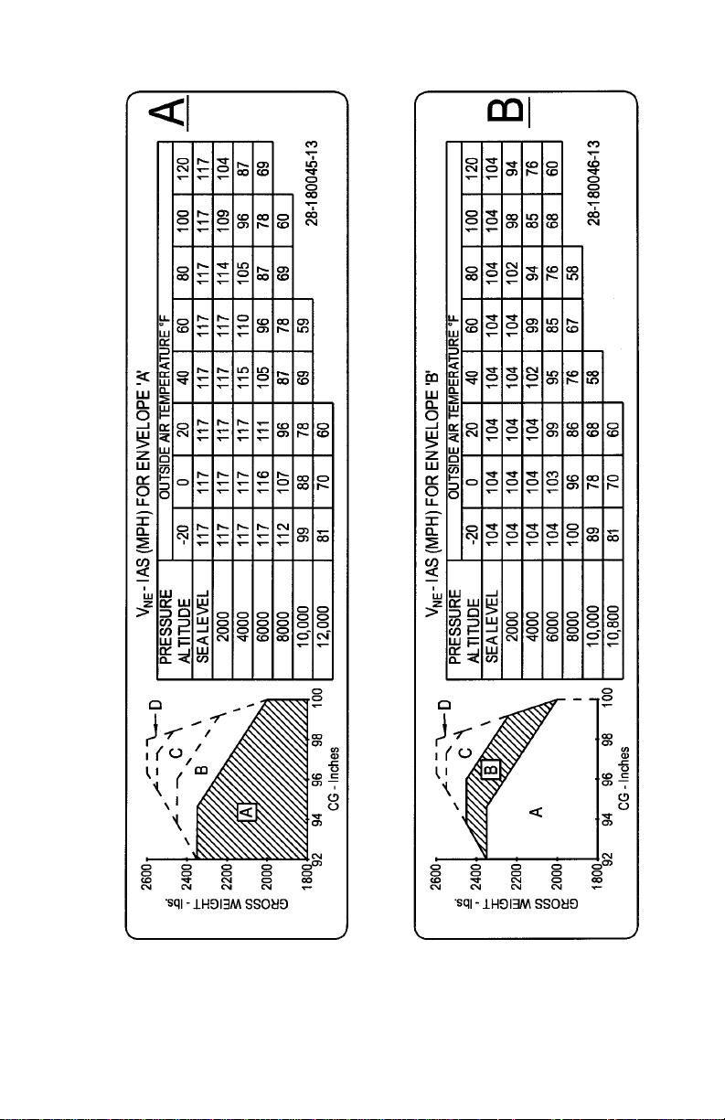
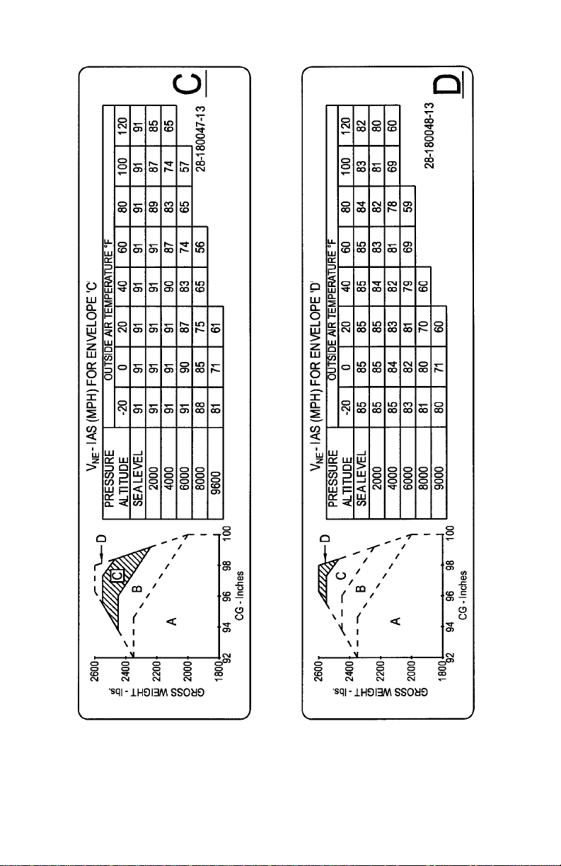
Figure 2-1. V
Placards – Envelopes A & B
NE
FAA Approved: Mar 26/12 Rev. 6
Report No. 28-AC-020 Feb 21/12
Page 34
2-12 ENSTROM 280FX OPERATOR’S MANUAL
This electronic document is not linked to a subscription for revision control or distribution. Refer to theTechnical
Publications Status link under the Technical Support Page of the Enstrom Helicopter website for the current revision
level of the 280FX Rotorcraft Flight Manual.
UNCONTROLLED COPY WHEN DOWNLOADED OR PRINTED
Figure 2-2. V
Placards – Envelopes C & D
NE
FAA Approved: Mar 26/12 Rev. 6
Report No. 28-AC-020 Feb 21/12
Page 35
ENSTROM 280FX OPERATOR’S MANUAL 2-13
This electronic document is not linked to a subscription for revision control or distribution. Refer to theTechnical
Publications Status link under the Technical Support Page of the Enstrom Helicopter website for the current revision
level of the 280FX Rotorcraft Flight Manual.
UNCONTROLLED COPY WHEN DOWNLOADED OR PRINTED
Figure 2-3. V
Placards – Envelope A & B (w/120°F)
NE
FAA Approved: Mar 26/12 Rev. 6
Report No. 28-AC-020 Feb 21/12
Page 36
2-14 ENSTROM 280FX OPERATOR’S MANUAL
This electronic document is not linked to a subscription for revision control or distribution. Refer to theTechnical
Publications Status link under the Technical Support Page of the Enstrom Helicopter website for the current revision
level of the 280FX Rotorcraft Flight Manual.
UNCONTROLLED COPY WHEN DOWNLOADED OR PRINTED
Figure 2-4. V
Placards – Envelope C & D (w/120°F)
NE
FAA Approved: Mar 26/12 Rev. 6
Report No. 28-AC-020 Feb 21/12
Page 37

ENSTROM 280FX OPERATOR’S MANUAL 2-15
This electronic document is not linked to a subscription for revision control or distribution. Refer to theTechnical
Publications Status link under the Technical Support Page of the Enstrom Helicopter website for the current revision
level of the 280FX Rotorcraft Flight Manual.
UNCONTROLLED COPY WHEN DOWNLOADED OR PRINTED
2. This placard is to be placed in the baggage compartment.
MAXIMUM WEIGHT IN THIS COMPARTMENT IS
108 LBS. OBSERVE C.G. AND GROSS WEIGHT
LIMITATIONS
3. This placard is to be placed on the clutch handle.
STOW FLAT ON FLOOR BEFORE FLIGHT
4. This placard is to be placed near the door handle.
EMERGENCY EXIT
PULL DOOR HANDLE TO OPEN CABIN DOOR
FAA Approved: Feb 11/13 Rev. 8
Report No. 28-AC-020 Jan 7/13
Page 38

2-16 ENSTROM 280FX OPERATOR’S MANUAL
This electronic document is not linked to a subscription for revision control or distribution. Refer to theTechnical
Publications Status link under the Technical Support Page of the Enstrom Helicopter website for the current revision
level of the 280FX Rotorcraft Flight Manual.
UNCONTROLLED COPY WHEN DOWNLOADED OR PRINTED
INTENTIONALLY LEFT BLANK
FAA Approved: Mar 26/12 Rev. 6
Report No. 28-AC-020 Feb 21/12
Page 39

ENSTROM 280FX OPERATOR’S MANUAL 3-1
This electronic document is not linked to a subscription for revision control or distribution. Refer to theTechnical
Publications Status link under the Technical Support Page of the Enstrom Helicopter website for the current revision
level of the 280FX Rotorcraft Flight Manual.
UNCONTROLLED COPY WHEN DOWNLOADED OR PRINTED
SECTION 3. EMERGENCY PROCEDURES
TABLE OF CONTENTS
PARAGRAPH DESCRIPTION PAGE
Table of Contents ........................... 3-1
General .......................................... 3-3
Paragraph 3-1 General .......................................... 3-3
3-2 Definition of Terms ......................... 3-3
3-3 After Emergency Action .................. 3-3
3-4 Emergency Exit .............................. 3-4
Engine ............................................ 3-5
Paragraph 3-5 Engine Failure ................................ 3-5
3-6 Low Engine Oil Pressure ................. 3-8
3-7 Turbocharger or Wastegate
Failure ............................................ 3-9
Ditching ....................................... 3-10
Paragraph 3-8 Ditching Without Power ................ 3-10
3-9 Ditching With Power ..................... 3-10
Rotors, Transmissions, and
Drive Systems .............................. 3-11
Paragraph 3-10 Rotor RPM Light Illumination ....... 3-11
3-11 Tail Rotor Malfunctions ................ 3-11
3-12 Main Rotor Gearbox and
Tail Rotor Gearbox ........................ 3-14
3-13 Clutch Disengagement Light
(CLUTCH ENGAGE) On ................ 3-15
Fire .............................................. 3-16
Paragraph 3-14 Fire in Flight ................................. 3-16
3-15 Fire on the Ground ....................... 3-16
Electrical System .......................... 3-17
Paragraph 3-16 Alternator Malfunction ................. 3-17
3-17 Starter Relay On ........................... 3-17
3-18 Engine Monitor Failure ................. 3-18
FAA Approved: Nov 26/13 Rev. 9
Report No. 28-AC-020 Nov 5/13
Page 40

3-2 ENSTROM 280FX OPERATOR’S MANUAL
This electronic document is not linked to a subscription for revision control or distribution. Refer to theTechnical
Publications Status link under the Technical Support Page of the Enstrom Helicopter website for the current revision
level of the 280FX Rotorcraft Flight Manual.
UNCONTROLLED COPY WHEN DOWNLOADED OR PRINTED
SECTION 3. EMERGENCY PROCEDURES
TABLE OF CONTENTS
PARAGRAPH DESCRIPTION PAGE
Fuel System .................................. 3-20
Paragraph 3-19 Electric Boost Pump Failure .......... 3-20
Flight Controls .............................. 3-21
Paragraph 3-20 Abnormal Vibrations ..................... 3-21
3-21 Cyclic Trim Failure ........................ 3-21
3-22 Lamiflex Bearing Failure ............... 3-23
FAA Approved: Nov 26/13 Rev. 9
Report No. 28-AC-020 Nov 5/13
Page 41

ENSTROM 280FX OPERATOR’S MANUAL 3-3
This electronic document is not linked to a subscription for revision control or distribution. Refer to theTechnical
Publications Status link under the Technical Support Page of the Enstrom Helicopter website for the current revision
level of the 280FX Rotorcraft Flight Manual.
UNCONTROLLED COPY WHEN DOWNLOADED OR PRINTED
SECTION 3. EMERGENCY PROCEDURES
GENERAL
3-1. General
This section describes the foreseeable system failures and
malfunctions that may occur and establishes the emergency
procedures used to maintain control and get the helicopter
safely on the ground.
3.2. Definition of Terms
1. Immediate Emergency Actions. Those actions that must
be performed immediately in an emergency procedure
are underlined. These immediate emergency actions
must be committed to memory.
NOTE
The urgency of certain emergencies requires
immediate and instinctive action by the pilot. The
most important single consideration is helicopter
control. All procedures are subordinate to this
requirement.
2. Urgency to Land
a. Land Immediately - Perform a landing at the closest
suitable landing site.
b. Land as Soon as Practicable - Land at the nearest
suitable airport or landing facility.
3-3. After Emergency Action
After a malfunction of equipment has occurred, appropriate
emergency actions have been taken and the helicopter is on
the ground, an entry must be made in the remarks section
of the aircraft log book describing the malfunction. The
helicopter shall not be flown until corrective action has
been taken.
FAA Approved: Nov 26/13 Rev. 9
Report No. 28-AC-020 Nov 5/13
Page 42

3-4 ENSTROM 280FX OPERATOR’S MANUAL
This electronic document is not linked to a subscription for revision control or distribution. Refer to theTechnical
Publications Status link under the Technical Support Page of the Enstrom Helicopter website for the current revision
level of the 280FX Rotorcraft Flight Manual.
UNCONTROLLED COPY WHEN DOWNLOADED OR PRINTED
3-4. Emergency Exit
To exit the cabin in the event of an emergency, first attempt
to open the doors. If the doors will not open, break the door
windows, overhead windows, or windshields as the
situation requires.
FAA Approved: Nov 26/13 Rev. 9
Report No. 28-AC-020 Nov 5/13
Page 43

ENSTROM 280FX OPERATOR’S MANUAL 3-5
This electronic document is not linked to a subscription for revision control or distribution. Refer to theTechnical
Publications Status link under the Technical Support Page of the Enstrom Helicopter website for the current revision
level of the 280FX Rotorcraft Flight Manual.
UNCONTROLLED COPY WHEN DOWNLOADED OR PRINTED
ENGINE
3-5. Engine Failure
The indications of an engine failure, either partial or
complete power loss, are a left yaw and a drop in engine
and main rotor RPM. If these conditions are encountered,
the procedures to be followed are determined by the altitude
and airspeed available to establish an autorotative glide,
while maintaining control of the helicopter and maintaining
sufficient rotor RPM for a successful landing.
NOTE
On aircraft S/N 2135 and prior, loss of rotor RPM
will result in a LOW ROTOR RPM warning light and
horn activation. On aircraft S/N 2136 and
subsequent, the ROTOR RPM warning light and
horn will activate when the rotor RPM exceeds the
upper limit and when the rotor RPM falls below the
lower limit.
1. Engine Failure – Altitude above 375 ft AGL
If engine failure occurs, proceed as follows:
a. Enter autorotation (collective full down, throttle to
idle, and right pedal to trim helicopter).
b. Stabilize at 58 MPH glide (best rate descent speed).
CAUTION
Due to high rates of descent, sustained autorotation
speed is limited to 85 MPH or V
for the operating
NE
condition. Maximum glide distance in autorotation
is attained at 80 MPH and 334 RPM. Reduce
collective to build RPM prior to touchdown.
c. Check engine and rotor RPM. Adjust collective to keep
rotor in green arc.
d. Select landing site.
FAA Approved: Nov 26/13 Rev. 9
Report No. 28-AC-020 Nov 5/13
Page 44

3-6 ENSTROM 280FX OPERATOR’S MANUAL
This electronic document is not linked to a subscription for revision control or distribution. Refer to theTechnical
Publications Status link under the Technical Support Page of the Enstrom Helicopter website for the current revision
level of the 280FX Rotorcraft Flight Manual.
UNCONTROLLED COPY WHEN DOWNLOADED OR PRINTED
NOTE
If engine is running and suitable landing site is not
within glide distance, the pilot should attempt to
fly the helicopter at reduced power settings to a
favorable landing area. The pilot should be prepared
for a complete loss of power at any time under
these conditions.
e. If engine is stopped, turn OFF fuel boost pump and
place mixture control in ICO position. If altitude and
time permit, see Air Restart, step 2, below.
f. At approximately 50 ft AGL, apply aft cyclic to reduce
speed.
g. Level helicopter with forward cyclic at an altitude
sufficient to provide tail rotor clearance. As helicopter
settles toward ground, apply up collective to cushion
landing.
h. Maximum recommended ground contact speed on
prepared surfaces is 35 MPH. Reduce speed on rough
surfaces.
CAUTION
Avoid rapid lowering of collective or use of aft
cyclic after ground contact or during ground slide.
2. Air Restart
If an engine failure occurs in flight, the decision to
attempt a restart will depend on the altitude and
potential landing areas available.
CAUTION
Helicopter control is primary concern after entering
autorotation. DO NOT attempt air restart if control
will be jeopardized. DO NOT attempt air restart
when below 3000 ft AGL.
FAA Approved: Nov 26/13 Rev. 9
Report No. 28-AC-020 Nov 5/13
Page 45

ENSTROM 280FX OPERATOR’S MANUAL 3-7
This electronic document is not linked to a subscription for revision control or distribution. Refer to theTechnical
Publications Status link under the Technical Support Page of the Enstrom Helicopter website for the current revision
level of the 280FX Rotorcraft Flight Manual.
UNCONTROLLED COPY WHEN DOWNLOADED OR PRINTED
a. Adjust collective as required to maintain rotor RPM in
green arc and establish 58 MPH autorotative glide.
b. Select landing site.
c. Grip cyclic between knees and with right hand turn
fuel boost pump OFF and pull mixture control to idle
cut off.
d. Rotate throttle to start position (start index up).
e. Engage starter.
f. When engine fires, mixture full rich and boost pump
ON.
g. Slowly increase throttle until engine and rotor tach
needles join in green arc.
3. Engine Failure – Altitude above 10 ft and below 375 ft
AGL
If an engine failure occurs at low altitude and low
airspeed, sufficient altitude may not be available to
increase rotor RPM. The collective must be adjusted for
the conditions in order to reach the touchdown point
without excessive rotor droop. The collective reduction
will vary from no reduction at zero airspeed and 10 feet
to full down collective at higher altitudes and airspeeds.
If engine failure occurs, proceed as follows:
a. Adjust collective to maintain rotor RPM, throttle to
idle position and right pedal to trim helicopter.
b. Adjust cyclic for autorotative glide.
NOTE
At higher altitudes and low airspeed use forward
cyclic to increase forward speed to approximately
58 MPH. At low altitudes and higher airspeed aft
cyclic will be required to reduce speed prior to
ground contact.
c. At altitude of approximately 50 ft AGL, use aft cyclic
to reduce forward speed.
FAA Approved: Nov 26/13 Rev. 9
Report No. 28-AC-020 Nov 5/13
Page 46

3-8 ENSTROM 280FX OPERATOR’S MANUAL
This electronic document is not linked to a subscription for revision control or distribution. Refer to theTechnical
Publications Status link under the Technical Support Page of the Enstrom Helicopter website for the current revision
level of the 280FX Rotorcraft Flight Manual.
UNCONTROLLED COPY WHEN DOWNLOADED OR PRINTED
d. Level helicopter with forward cyclic at an altitude
sufficient to provide tail rotor clearance.
e. As helicopter settles toward the ground, apply up
collective to cushion landing.
f. Maximum recommended ground contact speed on
prepared surfaces is 35 MPH. Reduce speed on rough
surfaces.
CAUTION
Avoid rapid lowering of collective or use of aft
cyclic after ground contact or during ground slide.
4. Engine Failure – At Hover in Ground Effect
Engine failure at a hover is indicated by a sudden yawing
of the helicopter to the left. Avoid sideward or rearward
movement after engine failure and proceed as follows:
a. Apply right pedal to prevent yawing and align skids in
direction of motion.
b. DO NOT reduce collective.
c. As helicopter settles to the ground, apply up collective
to cushion landing.
3-6. Low Engine Oil Pressure
1. Low Oil Pressure and Normal Oil Temperature
If low oil pressure is accompanied by normal oil
temperature there is a possibility the oil pressure gauge
or relief valve is malfunctioning. This is not necessarily
cause for an immediate precautionary landing. Proceed
as follows:
a. Land at nearest suitable landing area.
b. Inspect for and correct this source of trouble before
continuing flight.
FAA Approved: Nov 26/13 Rev. 9
Report No. 28-AC-020 Nov 5/13
Page 47

ENSTROM 280FX OPERATOR’S MANUAL 3-9
This electronic document is not linked to a subscription for revision control or distribution. Refer to theTechnical
Publications Status link under the Technical Support Page of the Enstrom Helicopter website for the current revision
level of the 280FX Rotorcraft Flight Manual.
UNCONTROLLED COPY WHEN DOWNLOADED OR PRINTED
2. Total Loss of Oil Pressure
If a total loss of oil pressure is accompanied by a rise in
oil temperature, this is a good indication that engine
failure is imminent. Proceed as follows:
a. Reduce engine power immediately.
b. Select a suitable forced landing field and land with
power.
3-7. Turbocharger or Wastegate Failure
Turbocharger or wastegate seizure will be evidenced by loss
of manifold pressure, if operating at manifold pressures
above ambient pressure. It should be possible to maintain
level flight at reduced airspeeds and altitudes as the engine
should be capable of maintaining manifold pressure equal
to ambient pressure. If the wastegate seizes, it may take
considerable force on the throttle twist grip to separate the
linkage between the throttle and the wastegate. If the
turbocharger seizes or the wastegate seizes in the full
bypass condition, proceed as follows:
1. Perform a power check to confirm power available for
landing.
2. Land as soon as practicable, using running landing
(reference Section 4, para. 4-18).
FAA Approved: Nov 26/13 Rev. 9
Report No. 28-AC-020 Nov 5/13
Page 48

3-10 ENSTROM 280FX OPERATOR’S MANUAL
This electronic document is not linked to a subscription for revision control or distribution. Refer to theTechnical
Publications Status link under the Technical Support Page of the Enstrom Helicopter website for the current revision
level of the 280FX Rotorcraft Flight Manual.
UNCONTROLLED COPY WHEN DOWNLOADED OR PRINTED
DITCHING
3-8. Ditching Without Power
If engine failure occurs over water, accomplish engine
failure emergency procedure and proceed as follows:
1. Unlatch doors.
2. Complete normal autorotational landing in water.
3. As collective reaches full up position and helicopter
settles in water, apply full lateral cyclic in direction
helicopter tends to roll.
WARNING
Clear helicopter as quickly as possible.
4. Pilot and passengers exit helicopter when main rotor
stops.
3-9. Ditching With Power
If ditching is unavoidable without other recourse, proceed
as follows:
1. Descend to low hovering altitude over water.
2. Unlatch both doors.
3. Exit passengers.
4. Hover clear of passengers.
5. Turn off master and alternator.
6. Close throttle and complete hovering autorotation.
7. As collective reaches full up position and helicopter
settles into water, apply full right lateral cyclic.
WARNING
Clear helicopter as quickly as possible.
8. Exit helicopter when rotor stops.
FAA Approved: Nov 26/13 Rev. 9
Report No. 28-AC-020 Nov 5/13
Page 49

ENSTROM 280FX OPERATOR’S MANUAL 3-11
This electronic document is not linked to a subscription for revision control or distribution. Refer to theTechnical
Publications Status link under the Technical Support Page of the Enstrom Helicopter website for the current revision
level of the 280FX Rotorcraft Flight Manual.
UNCONTROLLED COPY WHEN DOWNLOADED OR PRINTED
ROTORS, TRANSMISSIONS, AND DRIVE SYSTEMS
3-10. Rotor RPM Light Illumination (If Equipped)
If the ROTOR RPM warning light illuminates, immediately
lower the collective to increase the RPM or raise the
collective to reduce the RPM as required to return the RPM
to the normal operating range. The only exception to this
requirement is when the light illuminates because the RPM
is low during an autorotational flare immediately prior to
touchdown. After adjusting the collective, continue to
monitor the tachometer and control the RPM by
manipulating the throttle and collective.
3-11. Tail Rotor Malfunctions
Because of the many different malfunctions that can occur,
success in coping with tail rotor malfunctions depends
upon recognition of the condition and use of the proper
emergency procedure. The following is a description of the
three basic types of malfunctions and appropriate
emergency procedures to follow.
1. Complete Loss of Tail Rotor Thrust
This condition can be caused by a failure of the tail rotor
drive system or a failure of the control system which
would allow the blades to assume a neutral pitch
condition.
a. Hovering Flight
When tail rotor thrust is lost in hovering flight the
helicopter will rotate rapidly to the right, even with full
application of left pedal. Proceed as follows:
(1) Roll throttle off to full idle position. Helicopter will
slow down or stop rotation.
(2) As helicopter settles to ground, cushion landing
with up collective (throttle off).
b. During Flight
The helicopter will yaw to the right with full application
of left pedal.
FAA Approved: Nov 26/13 Rev. 9
Report No. 28-AC-020 Nov 5/13
Page 50

3-12 ENSTROM 280FX OPERATOR’S MANUAL
This electronic document is not linked to a subscription for revision control or distribution. Refer to theTechnical
Publications Status link under the Technical Support Page of the Enstrom Helicopter website for the current revision
level of the 280FX Rotorcraft Flight Manual.
UNCONTROLLED COPY WHEN DOWNLOADED OR PRINTED
If suitable landing area is not available within
autorotative glide distance, pilot should proceed as
follows:
(1) Use cyclic for directional control and collective and
power settings to maintain 60 to 80 MPH with the
yaw a maximum of 45°.
(2) Continue flight in this fashion using cyclic stick
for directional control until suitable autorotational landing site is reached.
(3) Complete autorotational landing.
2. Fixed Pitch Setting
This is a malfunction involving loss of control resulting
in a fixed pitch setting. Whether the nose will rotate left
or right depends upon the setting of the pedals when the
controls were jammed or locked.
a. Fixed Right Pedal
If the tail rotor pitch becomes fixed during an approach
or low power setting, the nose will turn to the right when
power is applied. Proceed as follows:
(1) Maintain 24 inches manifold pressure and 50
MPH.
(2) Fly to suitable area and complete a shallow power
on approach at 50 MPH.
(3) Adjust throttle and collective pitch so the
helicopter touches down straight ahead at an
airspeed of 0-10 MPH. Slight left or right throttle
adjustments can be used to control heading
during touchdown. Reduce throttle and collective
cautiously as skids contact surface.
CAUTION
DO NOT abort the emergency landing after airspeed
has diminished below 40 MPH.
FAA Approved: Nov 26/13 Rev. 9
Report No. 28-AC-020 Nov 5/13
Page 51

ENSTROM 280FX OPERATOR’S MANUAL 3-13
This electronic document is not linked to a subscription for revision control or distribution. Refer to theTechnical
Publications Status link under the Technical Support Page of the Enstrom Helicopter website for the current revision
level of the 280FX Rotorcraft Flight Manual.
UNCONTROLLED COPY WHEN DOWNLOADED OR PRINTED
b. Fixed Left Pedal
If the tail rotor pitch becomes fixed during cruise or high
power settings, the helicopter will yaw to the left when
power is reduced below 23 inches manifold pressure.
Power settings above 23 inches manifold pressure will
produce near normal flight conditions at airspeeds above
60 MPH. Proceed as follows:
(1) Fly to suitable landing area at a power setting of
at least 23 inches manifold pressure and 60 MPH
or above.
(2) Complete a shallow power-on approach at 60
MPH.
CAUTION
DO NOT AUTOROTATE.
(3) Adjust throttle and collective pitch so that the
helicopter touches down straight ahead at an
airspeed of 0-10 MPH.
(4) Reduce throttle and collective pitch cautiously as
skid gear contacts surface.
NOTE
Application of power to settings greater than 23
inches manifold pressure will make the helicopter
more controllable. Therefore, landing attempt may
be aborted and new approach initiated, if required.
3. Loss of Tail Rotor or Components
The amount of weight lost will determine the helicopter
reaction. If a small amount of weight is lost, the situation
would be similar to a loss of thrust situation. If a large
amount of weight is lost and there is a drastic forward
shift in c.g., immediate autorotation is the only
emergency procedure available.
FAA Approved: Nov 26/13 Rev. 9
Report No. 28-AC-020 Nov 5/13
Page 52

3-14 ENSTROM 280FX OPERATOR’S MANUAL
This electronic document is not linked to a subscription for revision control or distribution. Refer to theTechnical
Publications Status link under the Technical Support Page of the Enstrom Helicopter website for the current revision
level of the 280FX Rotorcraft Flight Manual.
UNCONTROLLED COPY WHEN DOWNLOADED OR PRINTED
3-12. Main Rotor Gearbox and Tail Rotor Gearbox
1. Main Rotor Transmission Temperature
If the main rotor transmission temperature exceeds red
line, reduce power. If the temperature remains above red
line, make a power-on landing as soon as possible.
2. Main Rotor Transmission Chip Light
If the main rotor transmission chip light (MRGB CHIP)
comes on in flight and the transmission temperature is
below the red line, monitor the temperature and land as
soon as practicable. On landing, remove and inspect the
chip detector (reference NOTE below).
If the main rotor transmission chip light is accompanied
by high transmission temperatures, land as soon as
possible.
3. Tail Rotor Transmission Chip Light
If the tail rotor transmission chip light (TRGB CHIP)
comes on in flight, make a power-on landing as soon as
practicable and inspect the chip detector (reference
NOTE below).
NOTE
New or recently overhauled gearboxes generally
generate a ferrous “fuzz” which will collect around
the chip detector as a gray sludge. This type of
contamination is normal and may be cleaned off
with a soft cloth, and the chip detector may be
reinstalled and the flight continued. Any metallic
chip greater than 1/16 inch in diameter or cross
section, or chip light accompanied by high
transmission temperature is cause for
discontinuation of normal flight. In the event of
finding large chips, please contact your nearest
Enstrom Service Center or the Enstrom Product
Support. Specific instructions in removal, checking,
and reinstallation of the chip detector may be
found in Section 8, para. 8-5, item 11.
FAA Approved: Nov 26/13 Rev. 9
Report No. 28-AC-020 Nov 5/13
Page 53

ENSTROM 280FX OPERATOR’S MANUAL 3-15
This electronic document is not linked to a subscription for revision control or distribution. Refer to theTechnical
Publications Status link under the Technical Support Page of the Enstrom Helicopter website for the current revision
level of the 280FX Rotorcraft Flight Manual.
UNCONTROLLED COPY WHEN DOWNLOADED OR PRINTED
3-13. Clutch Disengagement Light (CLUTCH ENGAGE)
On
Should the manual clutch become disengaged during flight,
it will result in an instantaneous engine overspeed and
severe left yaw if manifold pressure is much above idle.
These indications will be instantaneous and the pilot
should immediately enter autorotation. If the clutch
disengaged light illuminates without engine overspeed or
severe yaw, it may mean that a clutch disengagement is
probable or that the microswitch or electrical circuit has
malfunctioned. The pilot should proceed as follows:
1. Clutch Disengagement Light On with Motion Cues
a. Enter autorotation and reduce power to idle.
b. Perform autorotative landing.
c. Inspect for and correct the source of trouble before
continuing flight. Refer to the F-28F/280F Series
Maintenance Manual for engine overspeed troubleshooting (para. 3-3 G.).
2. Clutch Disengagement Light On Without Motion Cues
a. Reduce power and be prepared for sudden clutch
disengagement.
b. Land at nearest suitable landing area.
CAUTION
Be prepared for autorotation should clutch become
disengaged.
c. Inspect for and correct the source of trouble before
continuing flight.
FAA Approved: Nov 26/13 Rev. 9
Report No. 28-AC-020 Nov 5/13
Page 54

3-16 ENSTROM 280FX OPERATOR’S MANUAL
This electronic document is not linked to a subscription for revision control or distribution. Refer to theTechnical
Publications Status link under the Technical Support Page of the Enstrom Helicopter website for the current revision
level of the 280FX Rotorcraft Flight Manual.
UNCONTROLLED COPY WHEN DOWNLOADED OR PRINTED
FIRE
3-14. Fire in Flight
If fire, smoke, or the odor of smoke is detected in flight,
proceed as follows:
1. Turn the master and alternator switch to the OFF
position.
2. Land immediately using power-on approach.
3. If smoke obstructs vision, unlatch doors and let them
trail open.
4. Shut off engine as soon as helicopter is on the ground.
5. Shut fuel valve OFF.
6. Pilot and passengers clear the helicopter immediately.
3-15. Fire on the Ground
If fire, smoke, or the odor of smoke is detected, proceed as
follows:
1. Shut off engine and all switches.
2. Shut fuel valve OFF.
3. Pilot and passengers clear the helicopter immediately.
FAA Approved: Nov 26/13 Rev. 9
Report No. 28-AC-020 Nov 5/13
Page 55

ENSTROM 280FX OPERATOR’S MANUAL 3-17
This electronic document is not linked to a subscription for revision control or distribution. Refer to theTechnical
Publications Status link under the Technical Support Page of the Enstrom Helicopter website for the current revision
level of the 280FX Rotorcraft Flight Manual.
UNCONTROLLED COPY WHEN DOWNLOADED OR PRINTED
ELECTRICAL SYSTEM
3-16. Alternator Malfunction
A malfunction of the alternator will be indicated by zero
charge rate or constant discharge on the ammeter, or the
LOW VOLTAGE caution segment on later production
helicopter will illuminate. To put the alternator back on the
line, proceed as follows:
1. Alternator circuit breaker in.
2. Alternator excite circuit breaker in.
3. Cycle alternator switch.
4. If alternator is not restored or goes off the line again,
turn off all nonessential electrical equipment and land as
soon as practicable.
3-17. Starter Relay Light On
Later production helicopters are equipped with a STARTER
RELAY warning segment in the annunciator panel. This
light illuminates any time the main contacts of the starter
relay are closed. During normal operations, the only time
the light will illuminate is when the engine is being started.
Depending on the cause of the malfunction, there may be
significant power loss as the magnetos revert to the starting
configuration, that is, one magneto off and the other
running at retarded timing. If the STARTER RELAY light
illuminates when the engine is not being started, proceed as
follows:
1. Aircraft On Ground
a. Turn START switch/circuit breaker OFF.
(1) If light extinguishes, shut down the engine using
normal procedures and determine cause for the
light illumination.
(2) If light does not extinguish, proceed to next step.
b. Shut down the engine immediately.
c. Turn all electrical switches OFF.
FAA Approved: Nov 26/13 Rev. 9
Report No. 28-AC-020 Nov 5/13
Page 56

3-18 ENSTROM 280FX OPERATOR’S MANUAL
This electronic document is not linked to a subscription for revision control or distribution. Refer to theTechnical
Publications Status link under the Technical Support Page of the Enstrom Helicopter website for the current revision
level of the 280FX Rotorcraft Flight Manual.
UNCONTROLLED COPY WHEN DOWNLOADED OR PRINTED
d. Shut fuel valve OFF.
e. Pilot and passenger(s) clear the helicopter
immediately.
f. If possible, disconnect the battery.
2. Aircraft in Flight
a. Turn START switch/circuit breaker OFF.
(1) If light extinguishes, land as soon as practicable,
shut down the engine using normal procedures
and determine cause for the light illumination.
(2) If light does not extinguish, proceed to next step.
b. Land immediately using power-on approach.
c. Turn all electrical switches OFF.
d. Shut down the engine immediately after the helicopter
is on the ground.
e. Shut fuel valve OFF.
f. Pilot and passenger(s) clear the helicopter
immediately.
g. If possible, disconnect the battery.
3-18. Engine Monitor Failure
NOTE
The following applies to aircraft equipped with
either the GEM 600 series or the EDM-700 engine
monitors.
During flight, a faulty channel or probe will cause a missing
column or blank digital data on the engine monitor display.
Proceed as follows for the type of indication failure
encountered.
1. TIT indication failure:
a. Leave the mixture at the current setting as long as the
engine power is not increased. If the mixture was
leaned using TIT, enrich the mixture prior to
increasing the power setting.
FAA Approved: Nov 26/13 Rev. 9
Report No. 28-AC-020 Nov 5/13
Page 57

ENSTROM 280FX OPERATOR’S MANUAL 3-19
This electronic document is not linked to a subscription for revision control or distribution. Refer to theTechnical
Publications Status link under the Technical Support Page of the Enstrom Helicopter website for the current revision
level of the 280FX Rotorcraft Flight Manual.
UNCONTROLLED COPY WHEN DOWNLOADED OR PRINTED
NOTE
EGT indications are considered informational;
however, it is recommended to monitor remaining
EGT indications in the event one or more EGT
indication failure(s) occur while fuel mixture
leaning in flight.
2. EGT indication failure:
a. If one or more EGT indications fail, monitor the
remaining EGT indications and TIT.
b. If all EGT indications fail, monitor TIT.
NOTE
Primary CHT indication is provided by the CHT
gauge on the instrument panel. CHT indications
from the engine monitor are considered
informational only.
3. CHT indication failure:
a. If one or more CHT indications fail, monitor the
remaining CHT indications and the CHT indicator in
the instrument cluster.
b. If all CHT indications fail, monitor the CHT indicator
in the instrument cluster.
NOTE
Auxiliary indications (if equipped) are also
informational and will not affect further flight if a
failure occurs.
4. Other indication failure (if equipped; OAT, CLD, DIF,
BAT):
a. Any failure of these will not affect further flight.
FAA Approved: Nov 26/13 Rev. 9
Report No. 28-AC-020 Nov 5/13
Page 58

3-20 ENSTROM 280FX OPERATOR’S MANUAL
This electronic document is not linked to a subscription for revision control or distribution. Refer to theTechnical
Publications Status link under the Technical Support Page of the Enstrom Helicopter website for the current revision
level of the 280FX Rotorcraft Flight Manual.
UNCONTROLLED COPY WHEN DOWNLOADED OR PRINTED
FUEL SYSTEM
3-19. Electric Boost Pump Failure
WARNING
Illumination of the LOW FUEL PRESS warning light
can indicate fuel exhaustion and impending engine
stoppage.
Failure of the electric fuel boost pump will be indicated by
illumination of red, low boost warning light. With sufficient
fuel supply, the engine will continue to function.
If the LOW FUEL PRESS warning light comes on, verify fuel
quantity and land as soon as practicable. If fuel quantity is
zero or low, prepare for engine stoppage.
FAA Approved: Nov 26/13 Rev. 9
Report No. 28-AC-020 Nov 5/13
Page 59

ENSTROM 280FX OPERATOR’S MANUAL 3-21
This electronic document is not linked to a subscription for revision control or distribution. Refer to theTechnical
Publications Status link under the Technical Support Page of the Enstrom Helicopter website for the current revision
level of the 280FX Rotorcraft Flight Manual.
UNCONTROLLED COPY WHEN DOWNLOADED OR PRINTED
FLIGHT CONTROLS
3-20. Abnormal Vibrations
Vibrations in this helicopter can usually be classified as
either low frequency or high frequency. Low frequency
vibrations are generally caused by the main rotor system
while the high frequency vibrations usually originate from
the engine, drive system, or tail rotor. Any abnormal
vibrations are an indication that something is not correct
and should be referred to a mechanic before further flight. If
a vibration suddenly appears during a flight, it is an
indication that something has suddenly changed. The
helicopter should be landed as soon as practical and
inspected to find the cause of the vibration. After the cause
of the vibration has been identified, the pilot and the
mechanic can determine whether the helicopter can be
safely flown or should be repaired before further flight. An
abnormal vibration is reason to get the aircraft down as
soon as possible, but the pilot must also use caution and
select the safest possible landing site, working around
wires, people, and other obstructions.
3-21. Cyclic Trim Failure
Failure of the cyclic trim control system will result in either
inoperative trim or a trim runaway in one of the four
primary directions (forward, aft, left or right). If the trim
circuit breaker trips, it should be left out for the remainder
of the flight. Depending upon the failure mode and the flight
condition at the time of failure, the cyclic forces may be
relatively light or they may be excessive. The pilot should
evaluate the situation and determine if a precautionary
landing is indicated or if the flight should be completed as
planned. The pilot should be aware that the cyclic forces
will change between cruise flight and approach and landing.
If the trim stops operating when the switch is engaged, the
trim does not stop when the switch is released, or if the
circuit breaker trips, the operator should:
1. Immediately stop using the trim and pull the TRIM
circuit breaker to deactivate the circuit. Leave the circuit
breaker out for the remainder of the flight.
FAA Approved: Nov 26/13 Rev. 9
Report No. 28-AC-020 Nov 5/13
Page 60

3-22 ENSTROM 280FX OPERATOR’S MANUAL
This electronic document is not linked to a subscription for revision control or distribution. Refer to theTechnical
Publications Status link under the Technical Support Page of the Enstrom Helicopter website for the current revision
level of the 280FX Rotorcraft Flight Manual.
UNCONTROLLED COPY WHEN DOWNLOADED OR PRINTED
2. If the pilot determines the flight can be continued safely,
without use of the trim, flight may be continued to the
next destination.
3. If the pilot has any safety concerns, a landing should be
made as soon as practical.
a. If there is a significant reduction in the longitudinal
control, the pilot should plan a landing at a shallow
approach to an area where a run-on landing can be
made.
i. Avoid any maneuvers, such as rapid decelerations,
which may require forward cyclic for recovery.
ii. Perform a run-on landing as there may not be
enough forward cyclic to level the aircraft and stop
rearward motion if it is allowed to start drifting
rearward from a hover.
b. If there is a significant reduction in the lateral cyclic
control, it may be difficult or impossible to make
turns to the right.
i. The pilot should plan a landing to an area where
there is ample room to maneuver. The aircraft will
fly in a right crab, and maintaining a straight
course may be difficult.
ii. Lateral course corrections can be made using pedal
and longitudinal cyclic, but the aircraft may not be
aligned with the ground course.
iii. Perform an approach to a low hover; forward speed
can be stopped, but there may be some sideward
drift.
iv. Once forward speed is reduced in a low hover, the
pilot can roll off the throttle and align the aircraft
with the direction of motion using the pedals prior
to touching down.
v. If the pilot is having difficulty maintaining the
approach course, the pilot should consider making
a 360° turn to the right to line up on the final
approach again.
FAA Approved: Nov 26/13 Rev. 9
Report No. 28-AC-020 Nov 5/13
Page 61

ENSTROM 280FX OPERATOR’S MANUAL 3-23
This electronic document is not linked to a subscription for revision control or distribution. Refer to theTechnical
Publications Status link under the Technical Support Page of the Enstrom Helicopter website for the current revision
level of the 280FX Rotorcraft Flight Manual.
UNCONTROLLED COPY WHEN DOWNLOADED OR PRINTED
vi. Directional control is easier to maintain at
airspeeds above 60 knots, but the pilot must plan
to reduce forward speed prior to touchdown.
4. Ground the aircraft at the end of the flight. The aircraft
should be grounded until the problem is resolved by a
maintenance technician.
3-22. Lamiflex Bearing Failure
A lamiflex bearing failure will cause a rough ride. Initially,
this may be only a minor distraction, but in some cases, it
can progress quickly to the point where the bearing
physically comes apart. In this case, control of one blade
will be stiff, the main rotor will be severely out of balance,
and aircraft control may be in jeopardy. The following are
indications of a lamiflex bearing failure as it progresses.
1. A significant worsening of the ride quality from one flight
to the next or from one day to the next for no apparent
reason.
2. The aircraft cannot be trimmed at a hover or runs out of
trim at maximum forward flight speed when previously
there was no problem.
3. The collective suddenly ratchets when moved up and
down when previously it had been smooth or the
collective suddenly feels heavy.
4. The cyclic suddenly wobbles or moves in a circular
motion when previously it had been smooth.
5. The cyclic suddenly starts "chucking," (moving sharply in
a left rear to right forward direction in about a 3/4"
amplitude with a very crisp motion) especially at high
power or high airspeed.
WARNING
This last indication where the cyclic starts sharply
moving may be followed within a few minutes by a
total failure of the bearing.
FAA Approved: Nov 26/13 Rev. 9
Report No. 28-AC-020 Nov 5/13
Page 62

3-24 ENSTROM 280FX OPERATOR’S MANUAL
This electronic document is not linked to a subscription for revision control or distribution. Refer to theTechnical
Publications Status link under the Technical Support Page of the Enstrom Helicopter website for the current revision
level of the 280FX Rotorcraft Flight Manual.
UNCONTROLLED COPY WHEN DOWNLOADED OR PRINTED
Emergency Procedures – Impending Lamiflex Bearing
Failure
The following are the procedures to be used in dealing with
lamiflex failures. Refer to the preceding paragraph for the
description of the failure symptoms.
1. Moderate – Slight worsening in ride or not able to trim:
a. LAND – As soon as practicable. Have all three
bearings inspected before the next flight.
2. Serious – Ride continues to get worse or the cyclic or
collective start showing symptoms:
a. LAND – Immediately. Have all three bearings
inspected before further flight.
Emergency Procedures – Total Lamiflex Bearing Failure
The following are the procedures to be used in dealing with
total lamiflex bearing failure.
1. Maintain control of the aircraft.
2. Collective – Lower slowly. Commence an 800-900 ft/min
descent.
WARNING
Do NOT autorotate. Aircraft control at the
termination of an autorotation may be questionable
with a totally failed lamiflex.
3. Airspeed – Reduce to 50-60 MPH.
4. Rotor RPM – Reduce to minimum power on RPM.
5. Maneuvering – Minimize.
6. Land – Perform a running landing. Touch down at or
above Effective Translational Lift (ETL), approximately 20
knots if terrain permits.
FAA Approved: Nov 26/13 Rev. 9
Report No. 28-AC-020 Nov 5/13
Page 63

ENSTROM 280FX OPERATOR’S MANUAL 3-25
This electronic document is not linked to a subscription for revision control or distribution. Refer to theTechnical
Publications Status link under the Technical Support Page of the Enstrom Helicopter website for the current revision
level of the 280FX Rotorcraft Flight Manual.
UNCONTROLLED COPY WHEN DOWNLOADED OR PRINTED
WARNING
It may not be possible to control the aircraft in a
hover.
7. Shutdown – Complete.
FAA Approved: Nov 26/13 Rev. 9
Report No. 28-AC-020 Nov 5/13
Page 64

3-26 ENSTROM 280FX OPERATOR’S MANUAL
This electronic document is not linked to a subscription for revision control or distribution. Refer to theTechnical
Publications Status link under the Technical Support Page of the Enstrom Helicopter website for the current revision
level of the 280FX Rotorcraft Flight Manual.
UNCONTROLLED COPY WHEN DOWNLOADED OR PRINTED
INTENTIONALLY LEFT BLANK
FAA Approved: Nov 26/13 Rev. 9
Report No. 28-AC-020 Nov 5/13
Page 65

ENSTROM 280FX OPERATOR’S MANUAL 4-1
This electronic document is not linked to a subscription for revision control or distribution. Refer to theTechnical
Publications Status link under the Technical Support Page of the Enstrom Helicopter website for the current revision
level of the 280FX Rotorcraft Flight Manual.
UNCONTROLLED COPY WHEN DOWNLOADED OR PRINTED
SECTION 4. NORMAL PROCEDURES
TABLE OF CONTENTS
PARAGRAPH DESCRIPTION PAGE
Table of Contents ................................ 4-1
4-1 Preflight Planning ............................... 4-3
4-2 Preflight Inspection – General ............. 4-3
4-3 Before Preflight Inspection .................. 4-3
4-4 Preflight Inspection –
Fuel Management ............................... 4-5
4-5 Preflight Inspection – Exterior ............. 4-5
4-6 Before Starting Engine ...................... 4-11
4-7 Starting Engine ................................. 4-12
4-8 Starting Hot or Flooded Engine ......... 4-13
4-9 Rotor Engagement ............................ 4-14
4-10 Operational Checks .......................... 4-15
4-11 Before Takeoff ................................... 4-16
4-12 Takeoff to Hover ................................ 4-17
4-13 Normal Takeoff ................................. 4-18
4-14 Maximum Performance Takeoff ......... 4-19
4-15 Reserved ........................................... 4-20
4-16 Cruise ............................................... 4-20
4-17 Practice Autorotations ...................... 4-21
4-18 Landing ............................................ 4-22
4-19 Running Landing .............................. 4-22
4-20 After Landing .................................... 4-23
4-21 General Operation Procedures .......... 4-24
FAA Approved: Mar 26/12 Rev. 6
Report No. 28-AC-020 Feb 21/12
Page 66

4-2 ENSTROM 280FX OPERATOR’S MANUAL
This electronic document is not linked to a subscription for revision control or distribution. Refer to theTechnical
Publications Status link under the Technical Support Page of the Enstrom Helicopter website for the current revision
level of the 280FX Rotorcraft Flight Manual.
UNCONTROLLED COPY WHEN DOWNLOADED OR PRINTED
SECTION 4. NORMAL PROCEDURES
LIST OF FIGURES
FIGURE NO. DESCRIPTION PAGE
4-1 Strut Extension Check ........................4-5
FAA Approved: Mar 26/12 Rev. 6
Report No. 28-AC-020 Feb 21/12
Page 67

ENSTROM 280FX OPERATOR’S MANUAL 4-3
This electronic document is not linked to a subscription for revision control or distribution. Refer to theTechnical
Publications Status link under the Technical Support Page of the Enstrom Helicopter website for the current revision
level of the 280FX Rotorcraft Flight Manual.
UNCONTROLLED COPY WHEN DOWNLOADED OR PRINTED
SECTION 4. NORMAL PROCEDURES
4-1. Preflight Planning
1. Review and be familiar with Section 2, “Operating
Limitations”.
2. Calculate weight and balance and review loading
information in Section 6, “Weight/Balance and Loading”.
3. Obtain weather briefing and file flight plan.
4. Refer to Section 5, “Performance”, to determine if the
helicopter is within the limitations for planned loads,
winds, temperatures, and pressure altitudes.
NOTE
Pilot experience and training is another factor to
consider prior to conducting certain flights,
even if the helicopter is within its operating
envelope.
5. Check helicopter and engine log books to determine if
the helicopter is airworthy.
4-2. Preflight Inspection - General
The following checklists are designed to be used as a guide
while performing the preflight inspection. Thoroughly
familiarize yourself with the Maintenance Manual before
utilizing the checklists.
4-3. Before Preflight Inspection
1. Aircraft tie-downs and covers – Removed and stowed.
2. Publications – Check the cabin for the following items:
a. Standard Airworthiness Certificate, FAA Form 8100-2.
b. Certificate of Aircraft Registration, AC Form 8050-3.
c. Aircraft Radio Station License, FCC Form 556 (if
required).
FAA Approved: Mar 12/19 Rev. 12
Report No. 28-AC-020 Dec 3/18
Page 68

4-4 ENSTROM 280FX OPERATOR’S MANUAL
This electronic document is not linked to a subscription for revision control or distribution. Refer to theTechnical
Publications Status link under the Technical Support Page of the Enstrom Helicopter website for the current revision
level of the 280FX Rotorcraft Flight Manual.
UNCONTROLLED COPY WHEN DOWNLOADED OR PRINTED
NOTE
An Aircraft Radio Station License may not be
required for the aircraft. Refer to FCC WT Docket
No. 96-82 for more information.
d. 280FX Operator’s Manual.
e. Weight and balance forms (Figures 6-7 through 6-9)
for the helicopter to be flown. The serial number of
the helicopter to be flown should appear on these
forms.
NOTE
The above items are to be carried in U.S.
registered helicopter at all times. Owners and
operators of exported helicopters should check
with their own National Aviation Authority (NAA)
to determine documents required.
3. Master switch – ON.
4. Fuel quantity – check.
5. Lights – ON then OFF after check. Check landing, anticollision, position, and interior lights for condition and
security.
6. Annunciator panel – press to test – all lights should be
on when button (TEST) is pushed.
7. Master switch – OFF.
8. Ignition switch – OFF.
9. All other switches – OFF.
10. Fuel valve – ON.
11. Right side flight controls – check security if installed.
Check if properly stowed if removed.
12. Pedals – adjust as required.
13. Fire extinguisher – check for charge, condition, and
security.
FAA Approved: Mar 12/19 Rev. 12
Report No. 28-AC-020 Dec 3/18
Page 69

ENSTROM 280FX OPERATOR’S MANUAL 4-5
This electronic document is not linked to a subscription for revision control or distribution. Refer to theTechnical
Publications Status link under the Technical Support Page of the Enstrom Helicopter website for the current revision
level of the 280FX Rotorcraft Flight Manual.
UNCONTROLLED COPY WHEN DOWNLOADED OR PRINTED
4-4. Preflight Inspection – Fuel Management
1. Left fuel tank drain – Drain sample into jar. Verify the
fuel grade, check the cleanliness, and check that fuel is
free of water.
WARNING
Sample the left and right fuel tank sumps before
checking the fuel filter.
NOTE
Aircraft should be level or slightly nose down.
Rock the aircraft by moving the tail up and down
to displace any water or contaminants to the tank
sumps. If water is found, rock the aircraft and resample. Check the other tank. Repeat until no
water is found. Then check the fuel filter.
2. Right fuel tank drain – Drain sample into jar. Verify the
fuel grade, check the cleanliness, and check that fuel is
free of water.
3. Fuel filter – Secure and drain fuel sample into jar. Verify
the fuel grade, check the cleanliness, and check that fuel
is free of water.
4-5. Preflight Inspection – Exterior
1. Left door – check condition, security and latch operation.
2. Windshield – check condition.
3. Pitot tube – unobstructed.
4. Landing light – check condition.
5. Right door – check condition, security and latch
operation.
FAA Approved: Mar 26/12 Rev. 6
Report No. 28-AC-020 Feb 21/12
Page 70
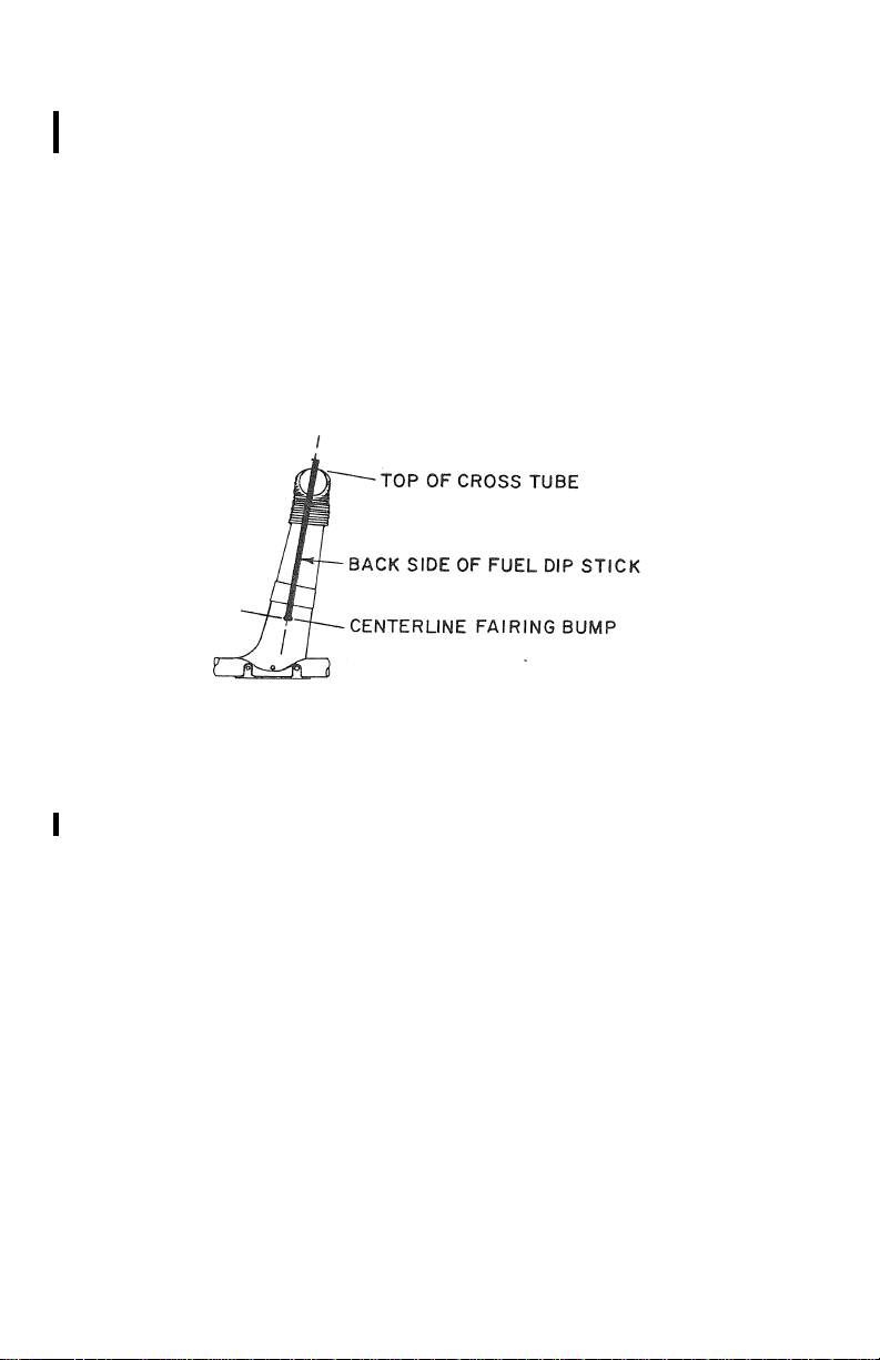
4-6 ENSTROM 280FX OPERATOR’S MANUAL
This electronic document is not linked to a subscription for revision control or distribution. Refer to theTechnical
Publications Status link under the Technical Support Page of the Enstrom Helicopter website for the current revision
level of the 280FX Rotorcraft Flight Manual.
UNCONTROLLED COPY WHEN DOWNLOADED OR PRINTED
6. Right oleo struts – check extension and security (para. 85, item 8, steps a, b, and c). The strut extension may be
checked with the backside of the fuel dipstick (reference
Figure 4-1).
NOTE
Align fuel dipstick with centerline on fairing
bump. Sight across top of cross tube. Normal
operating levels are indicated on the stick.
Figure 4-1. Strut Extension Check
7. Right landing gear – check condition and security. Check
ground handling wheel removed or in up position and
secured.
8. Right side engine compartment
a. Electrical wiring – condition and terminals tight.
b. Induction system – no obstructions, filter secure,
induction hose and lines secure and backfire and
alternate air doors free.
c. Fuel lines – secure and no signs of leakage.
d. Oil lines – secure and no signs of leakage.
e. Exhaust – no cracks or signs of leakage.
f. Cowl door – secure.
FAA Approved: Mar 26/12 Rev. 6
Report No. 28-AC-020 Feb 21/12
Page 71

ENSTROM 280FX OPERATOR’S MANUAL 4-7
This electronic document is not linked to a subscription for revision control or distribution. Refer to theTechnical
Publications Status link under the Technical Support Page of the Enstrom Helicopter website for the current revision
level of the 280FX Rotorcraft Flight Manual.
UNCONTROLLED COPY WHEN DOWNLOADED OR PRINTED
9. Upper inspection door
a. Swashplate and control rods – check condition and
security.
b. Fuel tank and lines – check for leaks and lines and
fitting secure.
c. Fire curtain – check condition.
10. Kick-in step door
a. Belt drive system – check security and condition of
idler pulley, and main drive belt.
b. Tail rotor drive shaft – check condition of flex
coupling.
c. Rotor tach drive – check condition.
d. Cooling fan – check condition.
e. Check main rotor gearbox sight gauge. Normal level
is halfway mark on sight gauge.
11. Right fuel tank
a. Check for leaks, check fuel quantity and cap
secured.
NOTE
When checking the fuel quantity, Enstrom
recommends using a calibrated dipstick.
CAUTION
If the fuel level indication on the dipstick is
lower than 1/4, take-off is not recommended.
12. From steps
a. Check main rotor gearbox filler cap closed.
b. Check area between fuel tanks for leaks and
obstruction to air flow.
c. Main rotor shaft – check condition.
FAA Approved: Mar 26/12 Rev. 6
Report No. 28-AC-020 Feb 21/12
Page 72

4-8 ENSTROM 280FX OPERATOR’S MANUAL
This electronic document is not linked to a subscription for revision control or distribution. Refer to theTechnical
Publications Status link under the Technical Support Page of the Enstrom Helicopter website for the current revision
level of the 280FX Rotorcraft Flight Manual.
UNCONTROLLED COPY WHEN DOWNLOADED OR PRINTED
d. Main rotor blades – security and condition, no bond
separations, cracks or corrosion. Main rotor
retention pins secured.
e. Check main rotor hub for security of all fasteners,
no cracks or obvious damage.
f. Main rotor pitch links – check for binding or
looseness.
g. Main rotor dampers – check for security and no
leakage.
13. Baggage box
a. Check contents secured. Observe weight
limitations.
b. Baggage box door secured.
14. Right static port – check unobstructed.
15. Right tail cone – check condition.
16. Tail rotor drive shaft – check condition and security of
drive shaft, hangar bearings and flex couplings
17. Right horizontal stabilizer – check condition and
security.
18. Right vertical stabilizer – check condition and security.
19. Right position and anti-collision lights – check security.
20. Tail rotor
a. Control cables – check condition, tension, and
security.
b. Tail rotor transmission – check for oil leakage and
check oil quantity. Check for security of attachment.
c. Tail rotor guard – check for security and evidence of
strike damage.
d. Pitch change mechanism – check condition and
operation. Check pitch links for binding or
looseness.
FAA Approved: Mar 12/19 Rev. 12
Report No. 28-AC-020 Dec 3/18
Page 73

ENSTROM 280FX OPERATOR’S MANUAL 4-9
This electronic document is not linked to a subscription for revision control or distribution. Refer to theTechnical
Publications Status link under the Technical Support Page of the Enstrom Helicopter website for the current revision
level of the 280FX Rotorcraft Flight Manual.
UNCONTROLLED COPY WHEN DOWNLOADED OR PRINTED
e. Tail rotor hub – check security. Check condition of
teeter stop bumpers.
f. Tail rotor blades – check security. Check for cracks
or bond separations. Check strike tabs for evidence
of strike.
21. Left horizontal stabilizer – check condition and
security.
22. Left vertical stabilizer – check condition and security.
23. Left position and anti-collision lights – check security.
24. Left tail cone – check condition.
25. Driveshaft cover – check security and condition.
26. Left static port – unobstructed.
27. Inspection door
a. Belt drive system – engage manual clutch and check
belt tensioning system for proper rigging. Disengage
manual clutch.
b. Cooling fan – check condition.
28. Left fuel tank
a. Check for leaks, check fuel quantity and cap
secured.
NOTE
When checking the fuel quantity, Enstrom
recommends using a calibrated dipstick.
CAUTION
If the fuel level indication on the dipstick is
lower than 1/4, take-off is not recommended.
29. Upper inspection door
a. Check engine oil quantity – 10 quarts full, 8 quarts
minimum for flight.
FAA Approved: Mar 12/19 Rev. 12
Report No. 28-AC-020 Dec 3/18
Page 74

4-10 ENSTROM 280FX OPERATOR’S MANUAL
This electronic document is not linked to a subscription for revision control or distribution. Refer to theTechnical
Publications Status link under the Technical Support Page of the Enstrom Helicopter website for the current revision
level of the 280FX Rotorcraft Flight Manual.
UNCONTROLLED COPY WHEN DOWNLOADED OR PRINTED
NOTE
Total oil capacity for the engine oil system
(including oil lines and coolers) is 10 quarts. The
engine oil sump capacity is 8 quarts. The engine oil
dip stick is marked to correspond with the engine
oil sump capacity of 8 quarts (full) and 6 quarts (low).
b. Swashplate and control rods – check condition and
security.
c. Fuel tank and lines – check for leaks, lines, fittings
and security.
d. Fire curtain – check condition.
30. Left engine compartment
WARNING
To prevent injury, use caution near exhaust system
components if the helicopter has been operated
within the last few hours.
a. Tailpipe – (first flight of the day) check for security
to the turbocharger. Firmly grasp the end of the
tailpipe and attempt to displace it. The tailpipe must
not be loose.
b. Turbocharger – check condition and security. Check
condition of thermal cover and check area around
turbocharger for evidence of heat damage.
c. Exhaust system and wastegate – check for security
and evidence of leakage. Wastegate linkage should
be in detent, throttle motion should be free and
unrestricted with associated wastegate motion.
d. Cowl door secure.
31. Left oleo struts – check extension and security
(reference step 6 above).
32. Left landing gear – check condition and security.
Ground handling wheel removed or in up position and
secured.
33. Main rotor blades – check condition of bonds,
FAA Approved: Mar 12/19 Rev. 12
Report No. 28-AC-020 Dec 3/18
Page 75

ENSTROM 280FX OPERATOR’S MANUAL 4-11
This electronic document is not linked to a subscription for revision control or distribution. Refer to theTechnical
Publications Status link under the Technical Support Page of the Enstrom Helicopter website for the current revision
level of the 280FX Rotorcraft Flight Manual.
UNCONTROLLED COPY WHEN DOWNLOADED OR PRINTED
corrosion, and condition and security of blade tape, if
installed.
34. Check operation of all lights for night flight.
4-6. Before Starting Engine
1. Seat belts fastened and doors latched.
2. Flight controls – check for full travel. Center cyclic and
pedals.
3. Throttle – OFF.
4. Set throttle friction so that slight effort is required to
rotate the throttle.
NOTE
For the throttle correlator to operate correctly,
the throttle friction must be set high enough to
prevent the throttle grip from turning on its own
when the collective is raised or lowered.
5. Collective full down and locked.
6. Fuel valve ON (in).
7. Heater as desired (in for OFF).
8. Rotor clutch disengaged.
CAUTION
Starting helicopter with clutch engaged will not
damage rotor system but will severely overload
the starter motor.
9. Mixture control in idle cutoff position.
10. Check magnetic compass.
11. Altimeter set to field elevation.
12. Radio(s) OFF.
13. All switches off and circuit breakers set.
FAA Approved: Mar 12/19 Rev. 12
Report No. 28-AC-020 Dec 3/18
Page 76

4-12 ENSTROM 280FX OPERATOR’S MANUAL
This electronic document is not linked to a subscription for revision control or distribution. Refer to theTechnical
Publications Status link under the Technical Support Page of the Enstrom Helicopter website for the current revision
level of the 280FX Rotorcraft Flight Manual.
UNCONTROLLED COPY WHEN DOWNLOADED OR PRINTED
4-7. Starting Engine
NOTE
If a headset is in use, it is recommended to
remove the headset during this sequence to be
able to hear the engine.
1. Collective down and locked.
2. Master switch ON.
3. Annunciator panel – press to test – all lights should be
on when button is pushed.
4. Alternator switch ON (OFF for APU start).
5. Starter relay switch/CB ON.
6. Trim motor switch ON or CB IN.
7. Throttle open (full).
8. Mixture control full rich.
9. Boost pump ON (1-8 seconds).
NOTE
The length of time the boost pump is run depends
upon the temperature of the engine. If the engine
is cold soaked in cold temperatures, it may
require 8 seconds or more. If the engine has just
been run, it may require one second or less.
10. Boost pump OFF.
11. Mixture control to idle cutoff (ICO).
12. Throttle closed. Then open to start position (i.e., index up).
Reference Section 7, “Aircraft and Systems Description”.
CAUTION
Excessive throttle opening on starting will result
in an engine overspeed which results in severe
engine damage.
FAA Approved: Mar 12/19 Rev. 12
Report No. 28-AC-020 Dec 3/18
Page 77

ENSTROM 280FX OPERATOR’S MANUAL 4-13
This electronic document is not linked to a subscription for revision control or distribution. Refer to theTechnical
Publications Status link under the Technical Support Page of the Enstrom Helicopter website for the current revision
level of the 280FX Rotorcraft Flight Manual.
UNCONTROLLED COPY WHEN DOWNLOADED OR PRINTED
13. Ignition switch ON to BOTH.
14. Engage starter button. When engine fires, release
starter button and push mixture control to full rich.
NOTE
If engine fails to start within 2-3 seconds, release
starter button, prime engine using steps 6-11.
15. Turn fuel boost pump ON.
16. Check engine oil pressure off “0” mark within 30
seconds.
17. Disconnect APU.
18. Alternator ON.
19. Check engine idle speed; should be 1450 to 1500 RPM.
NOTE
Mixture and RPM must be adjusted for change in
base altitude. (Reference the F-28F/280F Series
Maintenance Manual Paragraph 13-4.D(8).
Adjustments should be performed by
maintenance personnel only.)
20. AV MA, accessory switches ON, and headset(s) ON.
21. When engine oil pressure is above 25 psi and engine is
running smoothly, rotor may be engaged.
4-8. Starting Hot or Flooded Engine
1. Hot engine
a. Proceed with normal starting procedure (para. 4-7,
steps 1-5).
b. Prime engine 0-3 seconds.
c. Proceed with normal starting procedure (para. 4-7,
steps 10-13).
FAA Approved: Mar 12/19 Rev. 12
Report No. 28-AC-020 Dec 3/18
Page 78

4-14 ENSTROM 280FX OPERATOR’S MANUAL
This electronic document is not linked to a subscription for revision control or distribution. Refer to theTechnical
Publications Status link under the Technical Support Page of the Enstrom Helicopter website for the current revision
level of the 280FX Rotorcraft Flight Manual.
UNCONTROLLED COPY WHEN DOWNLOADED OR PRINTED
NOTE
If engine fails to start after 2-3 seconds, slowly
move mixture control to full rich position while
cranking engine. DO NOT engage starter for more
than 5 seconds in full rich position.
2. Flooded engine
a. Ignition switch in OFF position, throttle full open
and mixture control in ICO.
b. Press starter and crank engine for 3-5 seconds.
c. Throttle closed, then open to start index up position.
Ignition switch ON and proceed with normal starting
sequence (para. 4-7, steps 10-13).
4-9. Rotor Engagement
1. Check collective down and locked.
CAUTION
Heavy spring capsule forces are present with
zero or low rotor RPM, and damage to the
helicopter and engine can result if the collective
is allowed to rise.
CAUTION
Collective friction is to be used for ground
operation only.
2. Check pedals in neutral position.
3. Center cyclic with trim motors.
4. Check area for personnel and obstructions.
5. Maintain throttle in idle position (1450-1500 RPM) and
slowly engage clutch until engine RPM drops to 11001200 RPM.
FAA Approved: Mar 26/12 Rev. 6
Report No. 28-AC-020 Feb 21/12
Page 79

ENSTROM 280FX OPERATOR’S MANUAL 4-15
This electronic document is not linked to a subscription for revision control or distribution. Refer to theTechnical
Publications Status link under the Technical Support Page of the Enstrom Helicopter website for the current revision
level of the 280FX Rotorcraft Flight Manual.
UNCONTROLLED COPY WHEN DOWNLOADED OR PRINTED
6. When rotor RPM reaches 100 RPM, fully engage clutch.
NOTE
The clutch disengage warning light will go out
and the rotor RPM warning light will come on
when the clutch is fully engaged.
7. Place clutch handle in stowed position.
WARNING
Severe engine damage and complete loss of
power to rotor system will result if the manual
clutch is disengaged under any condition other
than throttle at idle position.
4-10. Operational Checks
NOTE
Mixture and RPM adjustments may be required
for change in base altitude.
1. Advance throttle to 1800 RPM and wait for cylinder head
temperature to reach 200°F.
2. After reaching 200°F cylinder head temperature, slowly
advance throttle to 2300 RPM and wait until oil
temperature reads 80°F.
3. Advance throttle to 3050 RPM. Low rotor RPM warning
light should go out at 334 rotor RPM (2900 engine RPM).
4. Check fuel flow 65-70 lb/hr (engine cold) (50-65 lb/hr
engine warm).
a. Adjust the fuel flow as required to attain 50-70
lbs/hr (as required) at full RPM (thus raising
EGT/TIT and reducing manifold pressure.)
5. Check manifold pressure 16-18 inches.
FAA Approved: Jul 27/15 Rev. 10
Report No. 28-AC-020 Apr 15/15
Page 80

4-16 ENSTROM 280FX OPERATOR’S MANUAL
This electronic document is not linked to a subscription for revision control or distribution. Refer to theTechnical
Publications Status link under the Technical Support Page of the Enstrom Helicopter website for the current revision
level of the 280FX Rotorcraft Flight Manual.
UNCONTROLLED COPY WHEN DOWNLOADED OR PRINTED
6. Move ignition switch to left position. Maximum 125 RPM
drop allowable in 5 seconds and maximum of 100°F rise
in TIT. Return switch to BOTH position and let RPM
stabilize. Move switch to right position. Maximum 125
RPM drop and maximum 100°F TIT rise allowable.
Return switch to the BOTH position.
NOTE
Engine should not run rough when operating on
one magneto.
7. Check engine driven fuel pump by turning off boost
pump and checking for no change in engine operation.
Observe red fuel pressure light on when boost pump is
off. Return boost pump switch to ON position and
observe proper light indication(s).
8. Gently close throttle to split tachometer needles to check
proper operation of overrunning clutch. When needles
join, return to operating RPM.
4-11. Before Takeoff
Check the following items for proper position or indication.
1. Seatbelts and doors latched.
2. Fuel valve ON (in).
3. Ammeter.
4. Main rotor gearbox temperature.
5. Fuel quantity.
6. Cylinder head temperature.
7. Engine oil temperature.
8. Engine oil pressure.
9. Mixture control set for 50-70 lb/hr fuel flow (as
required).
FAA Approved: Jul 27/15 Rev. 10
Report No. 28-AC-020 Apr 15/15
Page 81

ENSTROM 280FX OPERATOR’S MANUAL 4-17
This electronic document is not linked to a subscription for revision control or distribution. Refer to theTechnical
Publications Status link under the Technical Support Page of the Enstrom Helicopter website for the current revision
level of the 280FX Rotorcraft Flight Manual.
UNCONTROLLED COPY WHEN DOWNLOADED OR PRINTED
10. Boost pump ON and low fuel pressure light is off.
11. Anti-collision and other lights ON, as required.
12. Annunciator panel – press to test – all lights should be
on when button is pushed.
13. Throttle friction.
14. Release collective lock.
WARNING
Keep hand on collective and maintain down
position when lock is disengaged.
4-12. Takeoff to Hover
1. Cyclic in neutral position.
2. Set engine RPM to 3000 RPM with collective full down.
NOTE
As throttle is increased to 3050 engine RPM, the
rotor RPM warning light will go out when main
rotor reaches 334 RPM.
3. Slowly and smoothly increase collective pitch and adjust
throttle as required to maintain RPM in the green arc
while raising collective to lift helicopter off the ground.
The correlator will maintain RPM in the green if the
throttle grip is not allowed to move, and if the helicopter
is flown smoothly.
4. Check TIT 1450-1500°F.
a. If EGT/TIT is above 1500°F, land and richen the
mixture slightly.
b. If EGT/TIT is below 1450°F, the mixture can be
leaned for more power.
FAA Approved: Jul 27/15 Rev. 10
Report No. 28-AC-020 Apr 15/15
Page 82

4-18 ENSTROM 280FX OPERATOR’S MANUAL
This electronic document is not linked to a subscription for revision control or distribution. Refer to theTechnical
Publications Status link under the Technical Support Page of the Enstrom Helicopter website for the current revision
level of the 280FX Rotorcraft Flight Manual.
UNCONTROLLED COPY WHEN DOWNLOADED OR PRINTED
NOTE
This helicopter is equipped with a mechanical
throttle correlation device. The correlator will
compensate for changes in collective pitch when
manifold pressure is above 25 inches Hg and will
maintain RPM within the normal operating range
for normal hover maneuvering.
NOTE
Hovering IGE above 10,000 ft density altitude is
limited to 5 minutes.
CAUTION
Avoid maneuvers that require full pedal travel or
rapid pedal reversals.
4-13. Normal Takeoff
1. Align helicopter with desired takeoff course at a
stabilized hover height of approximately 2 ft.
2. Check power required to hover.
3. Smoothly apply forward cyclic to begin acceleration into
effective translational lift.
4. As the helicopter begins forward movement, maintain
altitude by increasing collective pitch.
NOTE
Adjust acceleration rate so approximately 1-2
inches of manifold pressure over hover power is
required. Maintain 2 ft hover altitude or lower
altitude if permitted by safe obstacle or terrain
clearance.
NOTE
During smooth transition into a climb from a
hover, there is a tendency for the RPM to climb
and exceed the red line. The pilot should
FAA Approved: Jul 27/15 Rev. 10
Report No. 28-AC-020 Apr 15/15
Page 83

ENSTROM 280FX OPERATOR’S MANUAL 4-19
This electronic document is not linked to a subscription for revision control or distribution. Refer to theTechnical
Publications Status link under the Technical Support Page of the Enstrom Helicopter website for the current revision
level of the 280FX Rotorcraft Flight Manual.
UNCONTROLLED COPY WHEN DOWNLOADED OR PRINTED
reduce throttle slightly in anticipation of this
increase. After this adjustment, the pilot should
not need to “chase” the RPM.
5. When effective translational lift has been attained, adjust
throttle as necessary to maintain RPM within the normal
operating range. Establish a positive rate of climb. Refer
to the Height-Velocity Diagram, Figure 5-5 or Figure 5-7,
for recommended takeoff profile.
4-14. Maximum Performance Takeoff
1. Stabilize at 2 ft hover aligned with desired takeoff course.
Check hover power.
2. Smoothly apply forward cyclic to begin acceleration into
effective translational lift.
3. As the helicopter begins forward movement, increase
collective pitch to maintain 2-5 ft skid height and 3050
RPM.
CAUTION
DO NOT exceed 39.0 inches of manifold pressure.
NOTE
Since the 280FX is equipped with a full-time
turbocharger, the aircraft is equipped with an
OVERBOOST warning light to warn the pilot of a
potential overboost condition. Transient
overboost conditions that may trigger the
warning light may not show as overboost
conditions on the manifold pressure gauge and
the overboost light may come on slightly before
the red line on the manifold pressure gauge. The
manifold pressure gauge, not the warning light,
is the determining factor in ascertaining the
magnitude of an overboost condition. Valid
overboost conditions must be logged in the
engine log and inspections performed per the
latest revision of Lycoming Service Bulletin 369.
FAA Approved: Jul 27/15 Rev. 10
Report No. 28-AC-020 Apr 15/15
Page 84

4-20 ENSTROM 280FX OPERATOR’S MANUAL
This electronic document is not linked to a subscription for revision control or distribution. Refer to theTechnical
Publications Status link under the Technical Support Page of the Enstrom Helicopter website for the current revision
level of the 280FX Rotorcraft Flight Manual.
UNCONTROLLED COPY WHEN DOWNLOADED OR PRINTED
4. After attaining translational lift, adjust throttle as
necessary to maintain RPM at 3050 RPM. Continue level
acceleration to 35 MPH, then apply aft cyclic to allow the
helicopter to climb and accelerate to best rate of climb
speed. Maintain constant airspeed. Climb at best climb
speed to clear barrier.
4-15. [Reserved]
4-16. Cruise
1. Maintain 3050 RPM and 29 inches manifold pressure, or
less, in level flight.
2. Set cyclic trim.
3. Lean fuel mixture to approximately 90 lb/hr at 29 inches
manifold pressure.
4. Monitor TIT.
NOTE
Allow a few minutes for temperature to stabilize.
DO NOT exceed 1650°F TIT. Make fine
adjustments to attain desired fuel flow and cross
check cylinder head temperature and oil
temperature. If temperatures are too high, enrich
mixture until temperatures remain within limits.
5. Any increase in power setting above 29 inches should be
accompanied by setting the mixture to full rich.
CAUTION
Avoid maneuvers that require full pedal travel or
rapid pedal reversals.
FAA Approved: Jul 27/15 Rev. 10
Report No. 28-AC-020 Apr 15/15
Page 85

ENSTROM 280FX OPERATOR’S MANUAL 4-21
This electronic document is not linked to a subscription for revision control or distribution. Refer to theTechnical
Publications Status link under the Technical Support Page of the Enstrom Helicopter website for the current revision
level of the 280FX Rotorcraft Flight Manual.
UNCONTROLLED COPY WHEN DOWNLOADED OR PRINTED
4-17. Practice Autorotations
1. Assure that helicopter is in a position to reach a
suitable landing area in autorotative glide.
2. Airspeed between 50 and 80 MPH.
3. Lower collective to full down position and needle will
split (i.e., DO NOT ADJUST THROTTLE). In the event a
power recovery is desired, raise collective to flight
condition. RPM will return to original setting.
4. Monitor rotor tachometer and adjust collective as
required to maintain rotor speed in green arc.
5. At approximately 50 ft AGL, apply aft cyclic to reduce
speed.
6. If touchdown autorotation is desired, roll off throttle to
idle position for landing before raising collective.
CAUTION
AVOID throttle chops to full idle at altitudes
7,000 ft above base altitude where engine idle
was adjusted. Engine idle speeds at altitude will
be less than those set at base altitude
conditions and engine stoppage is possible.
7. Level aircraft and cushion landing by raising collective.
8. If power recovery is desired, adjust throttle to maintain
engine RPM in the normal operating range. If the
throttle was not adjusted when the collective was
lowered, very little adjustment should be needed when
it is raised.
CAUTION
When making power recovery, avoid rapid
throttle movements until the rotor and engine
tachometer needles are joined to prevent
damage to the free-wheeling clutch.
FAA Approved: Nov 26/13 Rev. 9
Report No. 28-AC-020 Nov 5/13
Page 86

4-22 ENSTROM 280FX OPERATOR’S MANUAL
This electronic document is not linked to a subscription for revision control or distribution. Refer to theTechnical
Publications Status link under the Technical Support Page of the Enstrom Helicopter website for the current revision
level of the 280FX Rotorcraft Flight Manual.
UNCONTROLLED COPY WHEN DOWNLOADED OR PRINTED
4-18. Landing
1. Mixture control to 1450°F TIT.
2. Maintain RPM within normal operating range as
collective is reduced.
3. Landing light ON, if required.
4. Adjust collective and altitude to establish 8° to 10°
approach angle. Adjust airspeed to 60 MPH.
NOTE
During transition into a descent from cruise,
the RPM may have a tendency to fall below the
green arc. In this case, the pilot should
increase throttle slightly in anticipation of this
decrease. After this adjustment, the pilot
should not need to “chase” the RPM.
5. As the landing area is approached, reduce the airspeed
and rate of descent until a zero ground speed hovering
altitude of 2-5 ft is attained.
NOTE
Hovering IGE above 10,000 ft density altitude
is limited to 5 minutes.
4-19. Running Landing
1. Use shallow approach angle.
2. Maximum recommended ground contact speed on
smooth surface is 35 MPH. Reduce speed on rough
surfaces.
CAUTION
Avoid rapid lowering of collective pitch after
ground contact, as rapid deceleration and nose
down pitching may result.
FAA Approved: Mar 26/12 Rev. 6
Report No. 28-AC-020 Feb 21/12
Page 87

ENSTROM 280FX OPERATOR’S MANUAL 4-23
This electronic document is not linked to a subscription for revision control or distribution. Refer to theTechnical
Publications Status link under the Technical Support Page of the Enstrom Helicopter website for the current revision
level of the 280FX Rotorcraft Flight Manual.
UNCONTROLLED COPY WHEN DOWNLOADED OR PRINTED
4-20. After Landing
1. Collective down and locked.
2. Landing lights OFF.
3. Radio(s) OFF.
4. Reduce throttle to 2000 RPM for one minute.
5. Throttle to idle (1500 RPM).
6. Clutch disengaged.
CAUTION
Clutch disengagement with throttle open will
result in engine overspeed. Clutch disengagement is signaled by a red warning light on the
instrument console.
7. Idle engine at 1500 RPM for 2 minutes or until cylinder
head temperature cools to 300°F.
8. Boost pump OFF.
9. Mixture control to idle cutoff position.
10. Ignition switch OFF.
11. Master and all other switches OFF.
FAA Approved: Mar 26/12 Rev. 6
Report No. 28-AC-020 Feb 21/12
Page 88

4-24 ENSTROM 280FX OPERATOR’S MANUAL
This electronic document is not linked to a subscription for revision control or distribution. Refer to theTechnical
Publications Status link under the Technical Support Page of the Enstrom Helicopter website for the current revision
level of the 280FX Rotorcraft Flight Manual.
UNCONTROLLED COPY WHEN DOWNLOADED OR PRINTED
4-21. General Operation Procedures
Throughout the flight envelope, avoid maneuvers that
require full tail rotor pedal input or rapid tail rotor
reversals. Although this type of pedal input may be
necessary in some normal operations such as hovering
downwind or hovering in gusty conditions, the pilot should
avoid excessive pedal movement except as necessary for
normal flight operations.
FAA Approved: Mar 26/12 Rev. 6
Report No. 28-AC-020 Feb 21/12
Page 89

ENSTROM 280FX OPERATOR’S MANUAL 5-1
This electronic document is not linked to a subscription for revision control or distribution. Refer to theTechnical
Publications Status link under the Technical Support Page of the Enstrom Helicopter website for the current revision
level of the 280FX Rotorcraft Flight Manual.
UNCONTROLLED COPY WHEN DOWNLOADED OR PRINTED
SECTION 5. PERFORMANCE
TABLE OF CONTENTS
PARAGRAPH DESCRIPTION PAGE
Table of Contents ................................ 5-1
5-1 V
Density Altitude Charts ................ 5-3
NE
5-2 Effect of Loading on Choice of
H-V Envelope ...................................... 5-9
LIST OF FIGURES
FIGURE NO. DESCRIPTION PAGE
5-1 VNE Variation/Envelopes A-D .............. 5-4
5-2 Airspeed Calibration ........................... 5-5
5-3 Hover Ceiling In-Ground Effect ........... 5-6
5-4 Hover Ceiling Out-of-Ground Effect .... 5-7
5-5 Height Velocity Diagram
2350 lb Gross Weight ......................... 5-8
5-6 Effect of Loading on Choice of
H-V Envelope ...................................... 5-9
5-7 Height Velocity Diagram
2600 lb Gross Weight ....................... 5-10
5-8 Density Altitude Chart ...................... 5-11
5-9 Best Rate of Climb Speed .................. 5-12
FAA Approved: Mar 26/12 Rev. 6
Report No. 28-AC-020 Feb 21/12
Page 90

5-2 ENSTROM 280FX OPERATOR’S MANUAL
This electronic document is not linked to a subscription for revision control or distribution. Refer to theTechnical
Publications Status link under the Technical Support Page of the Enstrom Helicopter website for the current revision
level of the 280FX Rotorcraft Flight Manual.
UNCONTROLLED COPY WHEN DOWNLOADED OR PRINTED
INTENTIONALLY LEFT BLANK
FAA Approved: Mar 26/12 Rev. 6
Report No. 28-AC-020 Feb 21/12
Page 91

ENSTROM 280FX OPERATOR’S MANUAL 5-3
This electronic document is not linked to a subscription for revision control or distribution. Refer to theTechnical
Publications Status link under the Technical Support Page of the Enstrom Helicopter website for the current revision
level of the 280FX Rotorcraft Flight Manual.
UNCONTROLLED COPY WHEN DOWNLOADED OR PRINTED
SECTION 5. PERFORMANCE
5-1. V
The solid V
Density Altitude Chart
NE
/altitude curves shown in Figure 5-1 apply
NE
only to operation with the c.g. within the appropriate areas
shown in Figure 6-1.
Example: Helicopter c.g. is 96.0 inches at 2200 lb, use
Envelope A V
NE
.
Example: Helicopter c.g. is 93.0 inches at 2350 lb, use
Envelope A V
NE
.
Example: Helicopter c.g. is 96.5 inches at 2300 lb, use
Envelope B V
NE
.
Example: Helicopter c.g. is 95.0 inches at 2400 lb, use
Envelope B V
NE
.
Example: Helicopter c.g. is 98.0 inches at 2400 lb, use
Envelope C V
NE
.
Example: Helicopter c.g. is 96.0 inches at 2550 lb, use
Envelope C V
NE
.
Example: Helicopter c.g. is 97.0 inches at 2560 lb, use
Envelope D V
NE
.
NOTE
Use Figure 6-1 to determine actual location of c.g.
FAA Approved: Mar 26/12 Rev. 6
Report No. 28-AC-020 Feb 21/12
Page 92
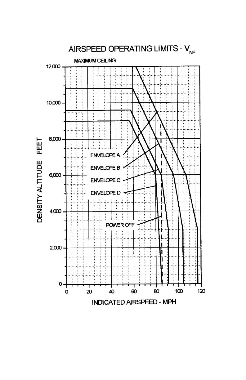
5-4 ENSTROM 280FX OPERATOR’S MANUAL
This electronic document is not linked to a subscription for revision control or distribution. Refer to theTechnical
Publications Status link under the Technical Support Page of the Enstrom Helicopter website for the current revision
level of the 280FX Rotorcraft Flight Manual.
UNCONTROLLED COPY WHEN DOWNLOADED OR PRINTED
Figure 5-1. V
Variation with Density Altitude
NE
FAA Approved: Mar 26/12 Rev. 6
Report No. 28-AC-020 Feb 21/12
Page 93
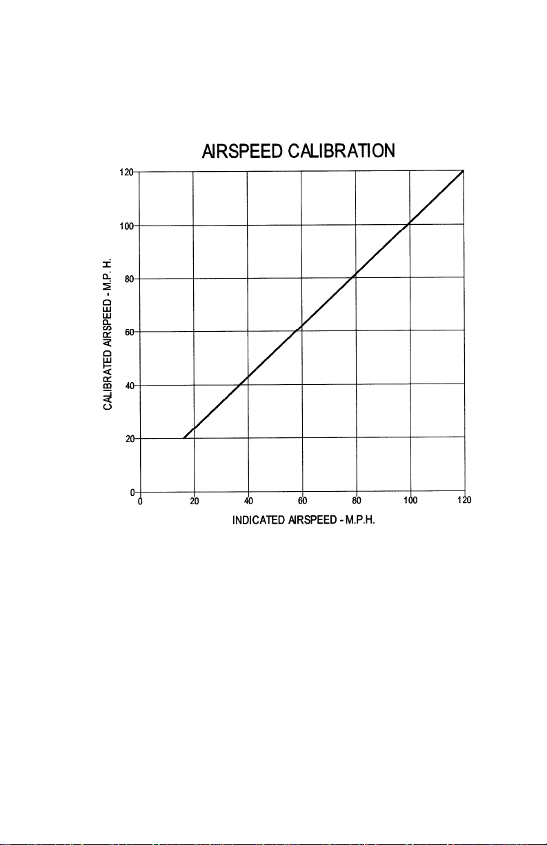
ENSTROM 280FX OPERATOR’S MANUAL 5-5
This electronic document is not linked to a subscription for revision control or distribution. Refer to theTechnical
Publications Status link under the Technical Support Page of the Enstrom Helicopter website for the current revision
level of the 280FX Rotorcraft Flight Manual.
UNCONTROLLED COPY WHEN DOWNLOADED OR PRINTED
Figure 5-2. Airspeed Calibration
NOTE
Indicated speeds below 20 MPH are not reliable.
FAA Approved: Mar 26/12 Rev. 6
Report No. 28-AC-020 Feb 21/12
Page 94
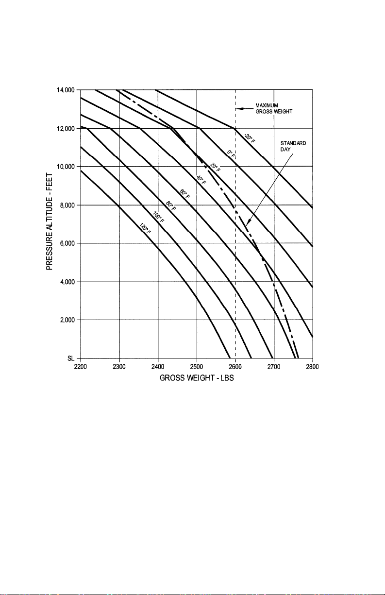
5-6 ENSTROM 280FX OPERATOR’S MANUAL
This electronic document is not linked to a subscription for revision control or distribution. Refer to theTechnical
Publications Status link under the Technical Support Page of the Enstrom Helicopter website for the current revision
level of the 280FX Rotorcraft Flight Manual.
UNCONTROLLED COPY WHEN DOWNLOADED OR PRINTED
Figure 5-3. Hover Ceiling In-Ground Effect
2 ft Skid Height
350 Rotor RPM
FAA Approved: Mar 26/12 Rev. 6
Report No. 28-AC-020 Feb 21/12
Page 95
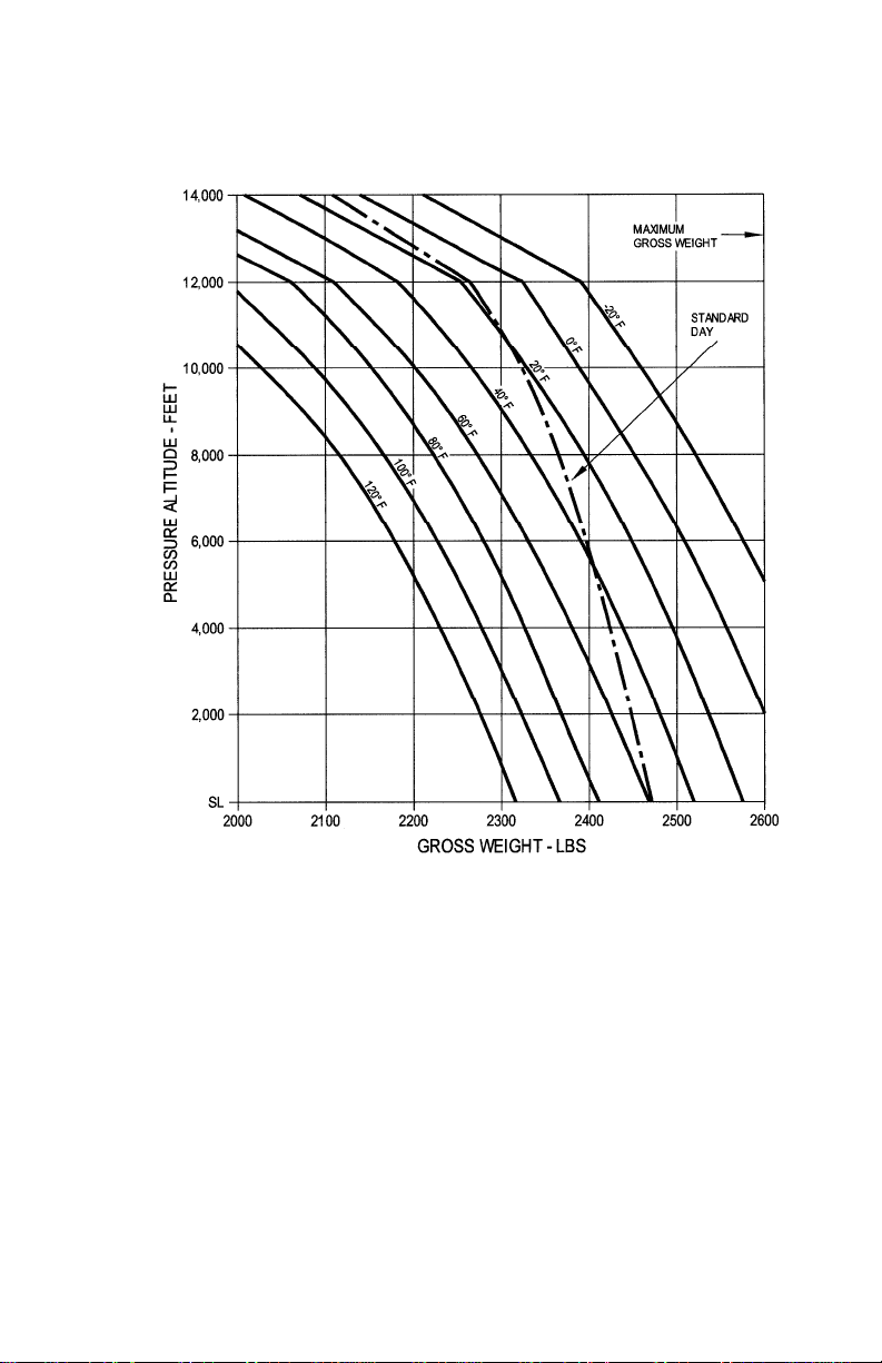
ENSTROM 280FX OPERATOR’S MANUAL 5-7
This electronic document is not linked to a subscription for revision control or distribution. Refer to theTechnical
Publications Status link under the Technical Support Page of the Enstrom Helicopter website for the current revision
level of the 280FX Rotorcraft Flight Manual.
UNCONTROLLED COPY WHEN DOWNLOADED OR PRINTED
Figure 5-4. Hover Ceiling Out-of-Ground Effect
40 ft Skid Height
350 Rotor RPM
FAA Approved: Mar 26/12 Rev. 6
Report No. 28-AC-020 Feb 21/12
Page 96
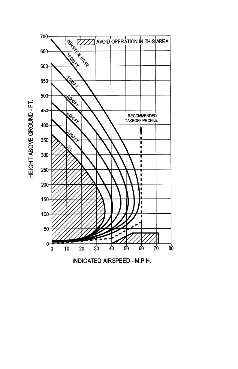
5-8 ENSTROM 280FX OPERATOR’S MANUAL
This electronic document is not linked to a subscription for revision control or distribution. Refer to theTechnical
Publications Status link under the Technical Support Page of the Enstrom Helicopter website for the current revision
level of the 280FX Rotorcraft Flight Manual.
UNCONTROLLED COPY WHEN DOWNLOADED OR PRINTED
Figure 5-5. Height Velocity Diagram
2350 lb Gross Weight
NOTE
Tests conducted on prepared surfaces.
FAA Approved: Mar 26/12 Rev. 6
Report No. 28-AC-020 Feb 21/12
Page 97
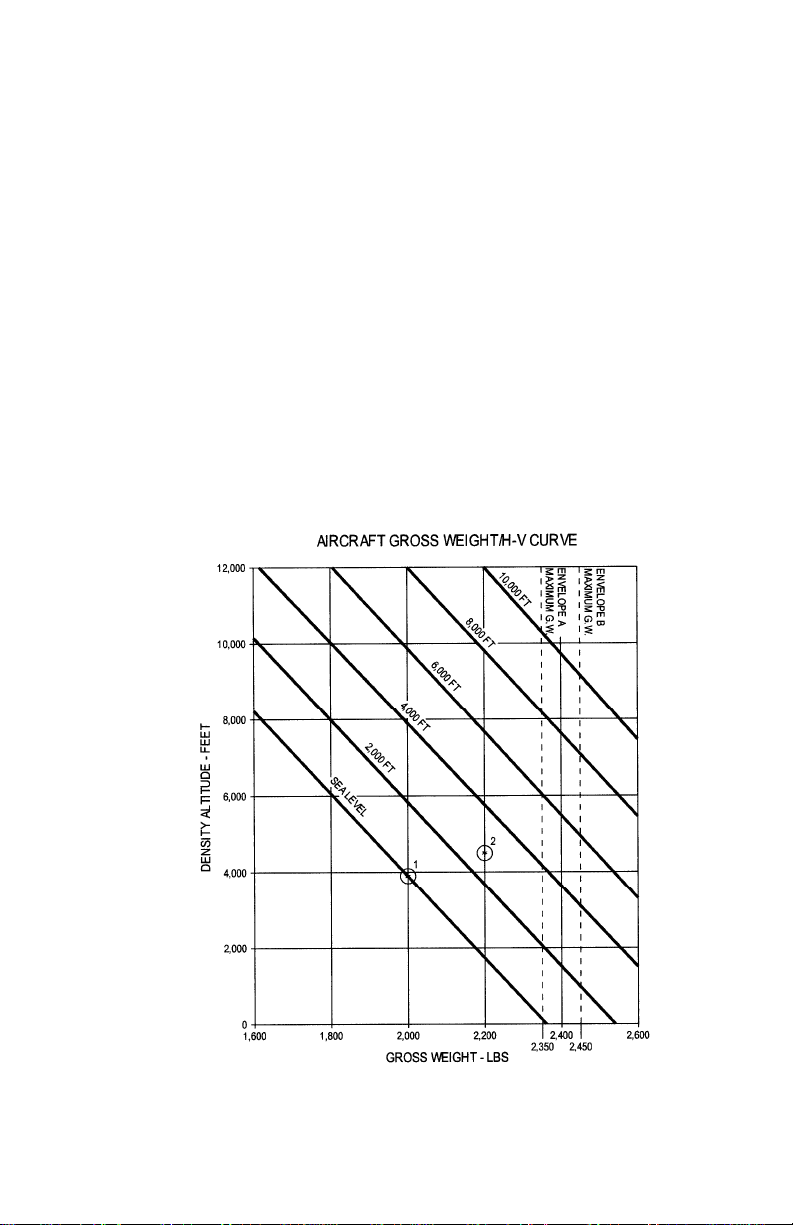
ENSTROM 280FX OPERATOR’S MANUAL 5-9
This electronic document is not linked to a subscription for revision control or distribution. Refer to theTechnical
Publications Status link under the Technical Support Page of the Enstrom Helicopter website for the current revision
level of the 280FX Rotorcraft Flight Manual.
UNCONTROLLED COPY WHEN DOWNLOADED OR PRINTED
5-2. Effect of Loading on Choice of H-V Envelope
The H-V curves presented in Figure 5-5 are valid for
operations at 2350 lb gross weight for the specific density
altitude conditions presented. For operation at other than
2350 lb gross weight, determine the proper H-V curve to be
used for the intended gross weight and density altitude for
the flight from the curves presented in Figure 5-6 below.
For operations above 2500 lb gross weight, use the H-V
curves presented in Figure 5-7 in place of Figures 5-6 and
Figure 5-5.
1. A gross weight of 2000 lb and 3900 ft H
would allow the
d
use of the sea level envelope.
2. A gross weight of 2200 lb and 4500 ft H
would require a
d
2800 ft curve. To be conservative, use the next higher
curve, 4000 ft.
Figure 5-6. Effect of Loading on Choice of H-V Envelope
FAA Approved: Mar 26/12 Rev. 6
Report No. 28-AC-020 Feb 21/12
Page 98
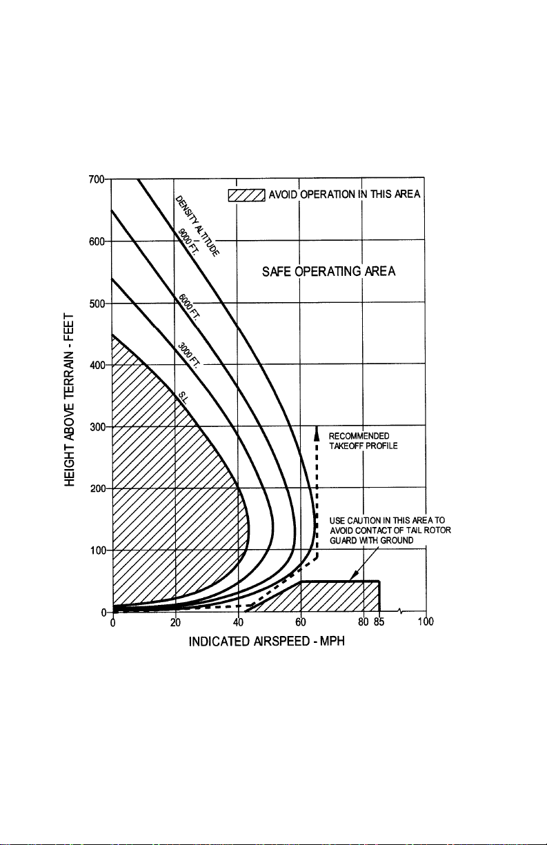
5-10 ENSTROM 280FX OPERATOR’S MANUAL
This electronic document is not linked to a subscription for revision control or distribution. Refer to theTechnical
Publications Status link under the Technical Support Page of the Enstrom Helicopter website for the current revision
level of the 280FX Rotorcraft Flight Manual.
UNCONTROLLED COPY WHEN DOWNLOADED OR PRINTED
NOTE
Altitude operations may also be limited by V
and
NE
OGE hover. Cross check Figure 5-1 and Figure 5-4
for intended operations when using this figure.
Figure 5-7. Height Velocity Diagram
2600 lb Gross Weight
FAA Approved: Mar 26/12 Rev. 6
Report No. 28-AC-020 Feb 21/12
Page 99
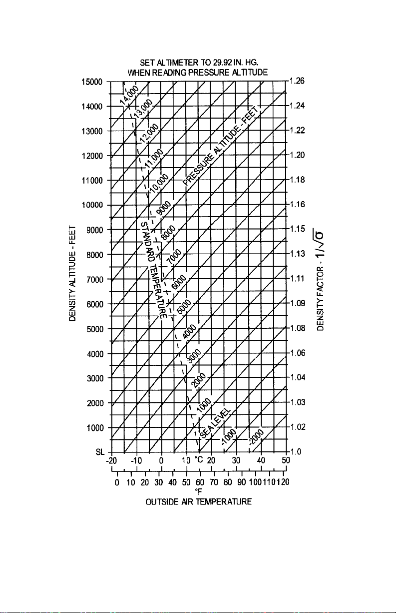
ENSTROM 280FX OPERATOR’S MANUAL 5-11
This electronic document is not linked to a subscription for revision control or distribution. Refer to theTechnical
Publications Status link under the Technical Support Page of the Enstrom Helicopter website for the current revision
level of the 280FX Rotorcraft Flight Manual.
UNCONTROLLED COPY WHEN DOWNLOADED OR PRINTED
Figure 5-8. Density Altitude Chart
FAA Approved: Mar 26/12 Rev. 6
Report No. 28-AC-020 Feb 21/12
Page 100
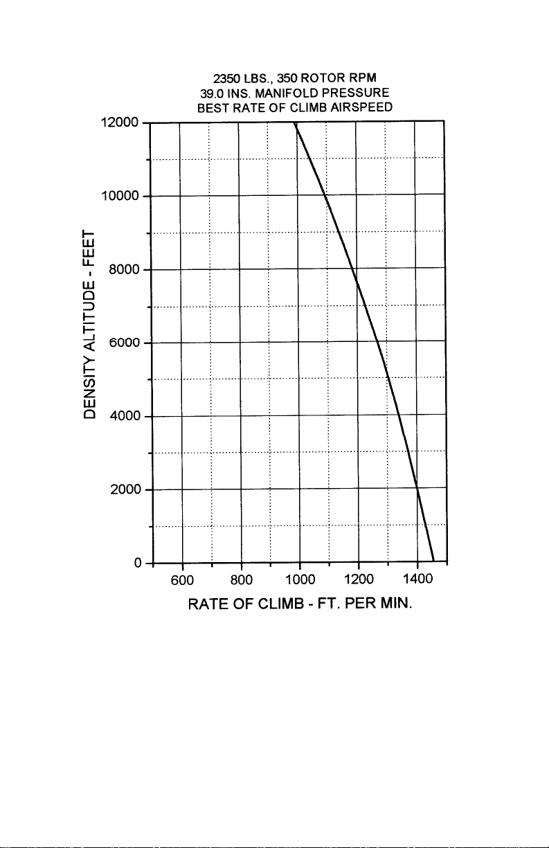
5-12 ENSTROM 280FX OPERATOR’S MANUAL
This electronic document is not linked to a subscription for revision control or distribution. Refer to theTechnical
Publications Status link under the Technical Support Page of the Enstrom Helicopter website for the current revision
level of the 280FX Rotorcraft Flight Manual.
UNCONTROLLED COPY WHEN DOWNLOADED OR PRINTED
Figure 5-9. Best Rate of Climb Speed
Best rate of climb speed varies with altitude from 57 MPH
IAS at SL decreasing to 48 MPH IAS at 12,000 ft H
FAA Approved: Mar 26/12 Rev. 6
Report No. 28-AC-020 Feb 21/12
.
d
 Loading...