

ensto EVH020.01R, EVH020.02R, EVH050.02R16, EVH020.01, EVH020.02 Installation And Operation Instructions Manual
...
Chago eFill
Installation instructions
ENG
Operation instructions
RAK 93
18.5.2018
©Ensto 2018

Contents
Chago eFill Charging Point 3
Introduction 3
Installation Instructions 3
Installation 3
Before Installation 3
Installation to Wall 3
EVH020.01R / EVH020.01R16 and EVH020.02R / EVH020.02R16 / EVH050.02R16 3
EVH020.01 and EVH020.02 / EVH050.02 4
Supply Connection EVH020.01 and EVH020.02 / EVH050.02 5
Charging Current Limitation 7
Top Cover Installation 8
Plug Holder Installation 8
User Instructions 9
Troubleshooting 9
The vehicle is not charging 9
The indicator light is red 9
The vehicle is charging slower than it should 10
Maintenance Instructions 10
Warranty 10
Dimension Drawing 11
Technical Data 12
2
RAK93 / © Ensto 2018

Chago eFill Charging Point
Introduction
This installation instruction and user guide is for the eFill charging point product family, which is a
range of home charging points with a xed cable solution. The eFill product family includes eight
versions.
EVH020.01R / EVH020.01R16 (Type1 plug) and EVH020.02R / EVH020.02R16 / EVH050.02R16 (Type2
plug) can be installed by a layman.
EVH020.01 (Type1 plug) and EVH020.02 / EVH050.02 (Type2 plug) must be installed by a qualied
person e.g. an electrician.
Even if the features and appearance of the dierent eFill versions varies, the installation and usage
of the product will always follow the principles described in this guide.
Installation Instructions
Installation
Delivery contains
• eFill charging point
• Plug holder
• Installation accessories
• Installation and Operation instruction
Items needed
• Ratchet wrench set
• Torx key set
• Power drill with bore bit
• Screws and possible accessories for wall installation
Before Installation
Remove the eFill from it’s package. Do not to scratch the surface of the eFill after removal from the
package.
Installation to Wall
When selecting the installation location, make sure that the wall material is suitable and robust. The
mounting surface should be at and vertical (± 10°).
EVH020.01R / EVH020.01R16 and EVH020.02R / EVH020.02R16 / EVH050.02R16
See gure 1.
• Make sure that the supply cable of 1,5 meters reaches the nearest outlet.
• Remove the mounting plate from the charging point by undoing the bolt on top.
• Place the mounting plate into the desired location on the wall.
• Attach the charging point on the mounting plate and tighten the bolt you loosened in place.
At the bottom of the wall bracket lies a small hole for padlock for extra security against theft
of the charging point.
• Install the plug holder in a suitable location near the charging point. See “Plug Holder Installa-
tion” and gure 5 on page 8.
RAK93 / © Ensto 2018
3

• Connect the supply cable plug into the outlet on the wall.
IMPORTANT NOTICE: eFill needs to be installed to a dedicated wall socket, which is equipped
with 30mA residual current device (RCD), also the cable and circuit breaker (MCB) must match
charging current setting in eFill. See table on page 7.
• When the light turns green, the charging point is ready for use.
Figure 1
EVH020.01 and EVH020.02 / EVH050.02
NOTE! The installation must be done by a qualied person e.g. an electrician.
See gure 2.
Figure 2
Cable lead through
plate orientation if
cable entry is from rear
Cable lead through
plate orientation if
cable entry is from bottom
Rubber washer
Possible supply cable
entry directions
4
RAK93 / © Ensto 2018
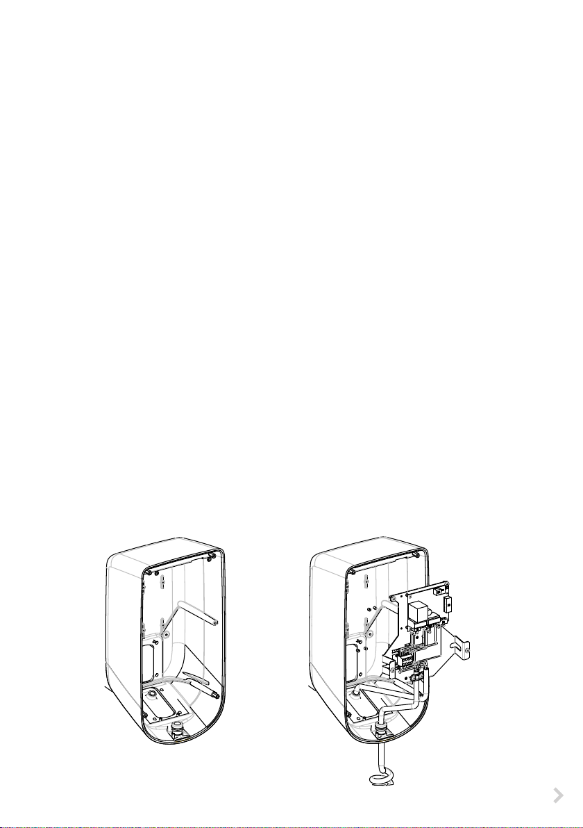
• Remove the stainless steel top cover by removing the four torx screws.
• Take the cable routing into consideration when planning the installation. The supply cable can
be routed into the enclosure from the rear or bottom. Install the lead through plate depending
on the cable entry direction.
• Prepare the wall for installation and select the screw type depending on the wall type. Recom-
mended screw diameter is 6mm - 8mm. The mounting screw spacing is 120mm x 185mm. Ex-
ercise extreme caution when drilling holes in the wall. Make sure there are no electrical cables
inside the wall.
• Select the drill size to match the screw size.
• Drill open the mounting hole points in the back of the aluminum enclosure.
• Install the aluminum enclosure to the wall.
• Place rubber washers between the wall and the enclosure.
Supply Connection EVH020.01 and EVH020.02 / EVH050.02
NOTE! The installation must be done by a qualied person e.g. an electrician.
The supply cable routing must be proper. Ensure the sucient supply cable sizes in the installation.
No additional loads in the same supply line.
See gure 3.
• Pull the supply cable through the cable lead through plate 350mm - 400mm measured from
the lead through.
• Remove the sheath of the supply cable at the length of max. 250mm.
• Cut the leads in dierent lengths so that the PE cable is the longest and strip them at the
length of 23mm.
• Connect the supply cable leads to the supply connectors according to the connection dia-
gram. Ensure strain relief to the cables by fastening it on the cable support that is located
under the supply connectors.
• In case of an eFill with a pushbutton, connect the cable of the pushbutton according to the
connection diagram.
IMPORTANT NOTICE: eFill needs to be installed to a dedicated supply line, which is equipped with
30mA residual current device (RCD) and 16A circuit breaker (MCB).
Figure 3
RAK93 / © Ensto 2018
5

EVH020.02
4
123
EVI020
IN OUT
L1 N L1 N PG CP
L1 N PEPE
SUPPLY
1 x 16A 230V
max 6mm² Cu
30mA RCD and 16A MCB
EVH020.01
4
123
EVI020
IN OUT
L1 N L1 N PG CP
PG = ProximityGround
CP = ControlPilot
PG = ProximityGround
CP = ControlPilot
DIP1 ON
DIP2 OFF
DIP3 ON
DIP4 OFF
DIP5 OFF
DIP6 OFF
DIP1 ON
DIP2 OFF
DIP3 ON
DIP4 OFF
DIP5 OFF
DIP6 OFF
X1 16A
CP
PE
PP
L1
L2
L3
N
X1 16A
L1 N PEPE
CP
N
PE
L1
PP
SUPPLY
1 x 16A 230V
max 6mm² Cu
30mA RCD and 16A MCB
6
RAK93 / © Ensto 2018

EVH050.02
1 2 3 4 5 6
ON
OFF
EVI020
IN OUT
L1 L1N N
2,5
2,5
2,5
2,5
SUPPLY
3 x 16A 230V
30mA RCD and 16A MCB
DIP1 ON
DIP2 OFF
DIP3 ON
DIP4 OFF
DIP5 OFF
DIP6 OFF
PE CP
1,5
1,5
2,5
2,5
2,5
2,5
2,5
2,5
2,5
L1 L2 L3PE PE PE PEN N N N
L1L1L2L2L3L3A1
K1
Contactor
A2
2,5
2,5
2,5
L1
L2 L3
X1 16A
CP
PP
L1
L2
PE
L3
N
Charging Current Limitation
Congure the maximum allowed charging current with DIP switches at the charging controller. The
maximum current can be dened according to the following table.
NOTE! The conguration must be done by a qualied person e.g. an electrician.
To get to the control unit the front cover must be removed by loosing the four torx screws.
DIP1 DIP2 DIP3 DIP4 DIP5 DIP6 Maximum charging current
OFF OFF OFF OFF OFF OFF 6A
ON OFF OFF OFF OFF OFF 8A (EVH020.01R / EVH020.02R default)
OFF ON OFF OFF OFF OFF 10A
ON ON OFF OFF OFF OFF 12A
OFF OFF ON OFF OFF OFF 14A
16A (EVH020.01 / EVH020.02 and
ON OFF ON OFF OFF OFF
RAK93 / © Ensto 2018
EVH020.01R16 / EVH020.02R16 default),
3 x 16A EVH050.02 / EVH050.02R16 default
7

Top Cover Installation
NOTE! The installation must be done by a qualied person
e.g. an electrician.
• Install the stainless steel top cover to it’s place with
four torx screws. See gure 4.
• After the eFill charging point is installed, turn on the
electricity to the supply line. When the green light in
the eFill cover turns on, the charging point is ready to
use for charging.
Plug Holder Installation
• Install the plug holder to a wall so that the plug is
handy to pick up and the placement is practical compared to location of the parked vehicle.
• When selecting the installation location, make sure
that the wall material is suitable and robust. The
mounting surface should be at and vertical (± 10°).
• Prepare the wall for installation and use screws delivered in the package.
• Install the holder to the wall. After installation, place
the charging plug to the holder. See gure 5.
Figure 4
Figure 5
8
RAK93 / © Ensto 2018

User Instructions
When you want to charge your vehicle, pick up the plug from the holder and connect it to your vehicle to start charging. When you want to stop charging your vehicle, disconnect the plug from the
vehicle and place it back to the holder.
If the charging point model has a stop button, push the stop button once to unlock the plug from
the vehicle before disconnecting the plug. Unlocking function depends on the vehicle model.
The eFill charging point has indicator lights to tell the status of the charging.
The charging sequence and indicator light operation is as follows:
Sequence Indicator
Ready to charge Green, stable
The charging cable is connected properly to the vehicle Green, blinking
The charging cable is connected and waiting for the vehicle to start
charging (for example timer charging)
Charging Blue, stable
The charging cable is connected and the vehicle has ended charging
(for example the battery is full)
Malfunction Red, stable
No supply power for charging point No light
Green, blinking
Green, blinking
Troubleshooting
The vehicle is not charging
• Ensure that the charging cable is properly connected to the vehicle.
• Ensure from the vehicle that the vehicle has no timer charging activated. If it is active, enable
instant charging from the vehicle.
• Ensure from the indicator light that the charging point supply power is on (the indicator light
is green). If not, check the status of the residual current device (RCD) and circuit breaker (MCB)
at the power supply line.
• Ensure that when you connect the charging cable to a vehicle, the indicator light blinks green
to indicate a good connection to the vehicle.
• Ensure from the charging point that the indicator light is not red.
The indicator light is red
Potential errors and corrective actions:
• Unsupported conguration on the eFill charging current limitation. Check the position on the
DIP switches inside the charging point according to the table on page 7. Notice that opening
can only be done by a qualied person e.g. an electrician.
• Missing protective earth (PE). Check the PE availability from the supply line and condition of
the charging cable.
• Error in the vehicle communication. Disconnect the vehicle, reset the charging point by turning supply voltage o and on. Retry charging.
RAK93 / © Ensto 2018
9

• Software error. Disconnect the vehicle, reset the charging point by turning supply voltage o
and on. Retry charging.
• The vehicle requires ventilation. In case the vehicle requires ventilation during charging, eFill
does not allow charging.
The vehicle is charging slower than it should
• Ensure from the vehicle that the vehicle has no timer charging activated. If the timer charging
is activated, the charging time may be dierent than expected.
• Ensure from inside of the charging point the conguration of the current limitation DIP switches. Notice that opening can only be done by a qualied person e.g. an electrician. If the charging current limitation is set to a lower charging current than assumed, the charging time is
longer.
• Ensure that there is no charging current limitation features in use at the vehicle.
If you need to contact Ensto related to faulty operation of Chago eFill, prepare to tell the order num-
ber (V.......). You will nd the order number on the nameplate on the enclosure bottom.
Maintenance Instructions
With well-done maintenance you can ensure a long lifetime of the charging point and keep the
warranty valid.
Please proceed the following maintenance once in a month:
• Test the residual current device (RCD) at the supply line. Usually RCD’s have a test button for
this purpose. There might be local requirements on the RCD manual test interval, but Ensto
recommends testing once a month. In case of failed test the RCD must be changed.
• Check the plug holder and the charging plug from possible dirt. Remove possible dirt.
• Check the condition of the charging plug and the charging cable for wear out or mechanical
damage. If damaged, please replace necessary parts with new ones.
Warranty
The warranty period for Ensto electric vehicle charging point is 3 years from the date of purchase
but no longer than 4 years from the date of manufacture, if there is no other agreement. The warranty is not applicable if the maintenance is not performed according to the instructions.
Warranty conditions, see www.ensto.com.
10
RAK93 / © Ensto 2018

Dimension Drawing
EVH020.01 / EVH020.02 / EVH050.02
432
220
168
EVH020.01R / EVH020.01R16 and EVH020.02R / EVH020.02R16 /EVH050.02R16
432
363200
363
140
1500
RAK93 / © Ensto 2018
220
495
200
168
11
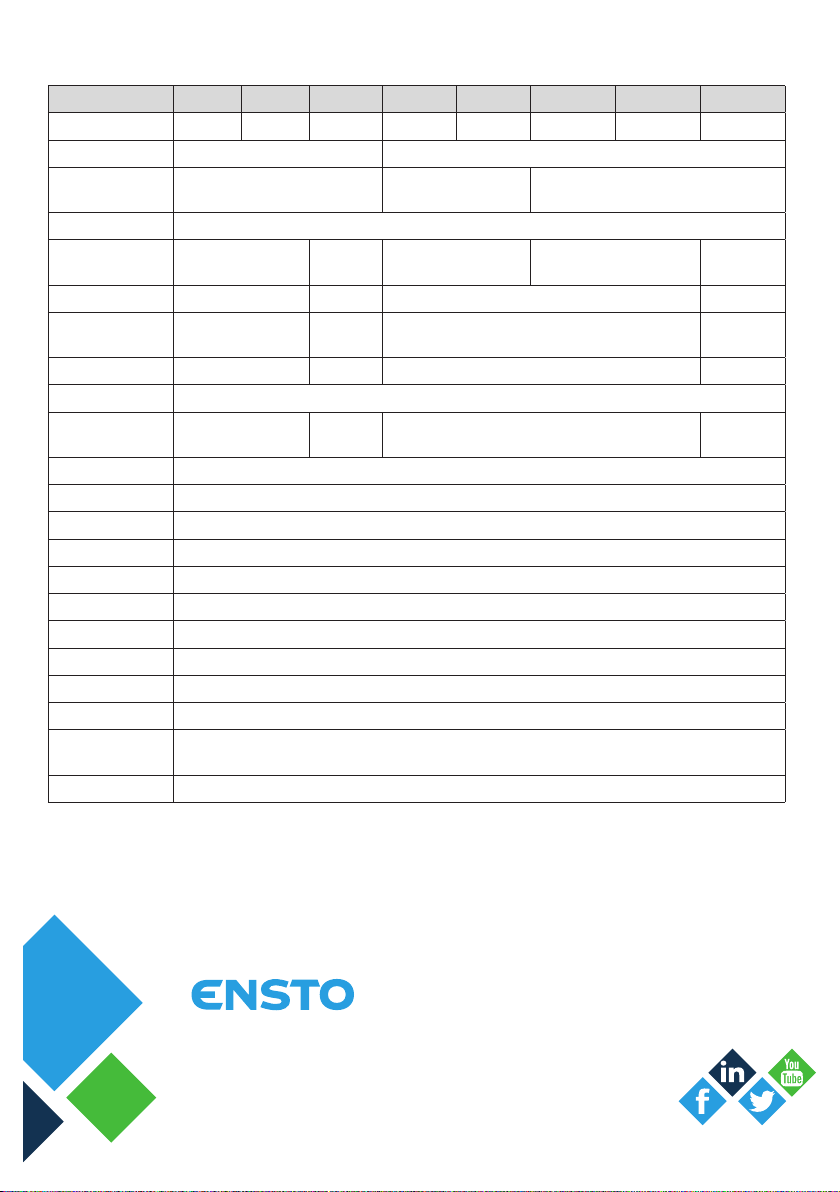
Technical Data
Product code EVH020.01 EVH020.02 EVH050.02 EVH020.01R EVH020.02R EVH020.01R16 EVH020.02R16 EVH050.02R16
Charging connector Type1 plug Type2 plug Type2 plug Type1 plug Type2 plug Type1 plug Type2 plug Type2 plug
Supply cable - 1,5 m
Supply coupler
Charging connectors 1
Charging current max.
Charging output 3.6 kW 11 kW 3.6 kW 11 kW
Nominal voltage
Nominal current 1 x 16 A 3 x 16 A 1 x 16 A 3 x 16 A
Nominal frequency AC 50/60 Hz
Supply connectors
Supply connector type Screw terminal Cu 2,5 - 6 mm²
No of cable throughs 1
Installation Directly to wall
Dimensions 432 x 220 x 168 mm
Weight 9 kg
Lenght of charging cable 4 m
Enclosure class IP44
Shock protection rate IK10
Operating temperature -30 … +50 C
Operating humidity 95% non condensating
Standby power consumption
Functional features Status indicator LED’s
16A 1-phase
230V 1-phase
- CEE 7/7 plug (Schuko)
3 x 16A
3-phase
230V/400V
3-phase
3 (N, L, PE)
5 (L1, L2
L3,N, GND)
8A 1-phase 16A 1-phase 3 x 16A 3-phase
230V 1-phase
3 (N, L, PE)
<1W typical
Industrial CEE Plug 16A 5-pole
(standard IEC 60309)
230V/400V
3-phase
5 (L1, L2 L3,N,
GND)
ensto.com
Ensto Chago Oy
Ensio Miettisen katu 2, P.O. Box 77
FIN-06101 Porvoo, Finland
Tel. +358 20 47 621
Support: https://www.ensto.com/support/service-request/
 Loading...