

EnStar Split Wall Mounting Type, Split Wall Mounting Type Room Air Conditioner Installation Manual
Page 1
INSTALLATION MANUAL FOR ROOM
AIR CONDITIONER
(Split Wall Mounting Type)
For correctinstallation, read thismanual before startinginstallation. Please savethis manual ina safeplace.
Only trained and qualified service personnel should install, repair or service air conditioning equipment.
Users shouldnot install theair conditioner bythemselves.
Pictures in this manual may be slightly different from the air conditioner you purchased. These pictures
are onlysketches.
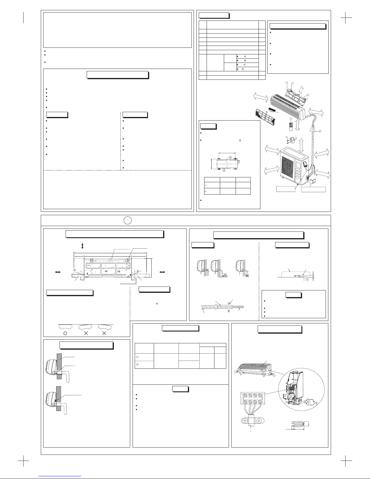
INSTALLATION PRECAUTION
Installation in the following places may cause trouble. If it is unavoidable to use in such places, please
consult withthe dealer:
A placefull of machine oil.
A salineplace such ascoast.
A placefull of sulfide g s suchas hot-spring resort.
Places where there are high frequency machines such as wireless installation, welding machine, and
medical facility.
A placeof special environmentalconditions.
a
Indoor Unit
place whichcan bear theweight of the indoorunit.
place which provides the spaces around the
indoor unitas required rightin the diagram.
A place which is far from heat, steam and
inflammable gas.
A place where is no obstacle near the inlet and
outlet area.
A
A
A place 1m or more from TV, radio instrument, in
the centerof the roomis perfect.
Outdoor Unit
A place, which is convenient to installation and
not exposedto a strongwind.
A place can bear the weight of the outdoor unit
and where the outdoor unit can be held in the
horizontal position.
A place where the operation noise and discharge airdo not disturbyou neighbor.
A placefree of a leakageof combustible gases.
An allowable head level at the connective
piping is less than 5m and length of the
connective pipingis up lessthan 10m.
A place, which provides the spaces around the
outdoor unitas required rightin the diagram.
Unavailable tochildren.
NOTE:
The appliance shall not be installed in the laundry. All the connection must be in accordance with
national regulations.
For detailed installation acceptance, please refer to your contract with the power supplier if restrictions
do applyfor products likewashing machines, airconditioners or electrical ovens.
For powerdetails of the air conditioner, refer tothe rating plateof the product.Contact your local dealer if
you have any questions.
1.
2.
3.
Cautions on remote controller installation
Before installation, operate the remote
controller to determine its location in a
reception range.
Keep the remote controller at least 1m
apart from the nearest TV set or stereo
equipment.
Do not install the remote controller in a
place exposedto direct sunlightor close
to aheating source, suchas astove.
Note that the positive and negative
poles are right positions when loading
batteries.
Caution
If needsuspending installation, consults
the correspondingrequirement.
INDOOR UNIT INSTALLATION
1
1. Cutting A Hole and Mounting Installation Plate
Installation Plate and Its Measures (Unit: mm)
1. Fix the installation plate.
Install the installation plate horizontally on structural
members in the wallwith the spaces providedaround the
plate.
In case of block, brick, concrete or similar type walls,
make 5mm dia, holes in the wall. Insert clip anchors for
appropriate mountingscrews.
Fix theinstallation plate on thewall.
1.
2.
3.
2. Cutting a hole.
Determine the pipe hole position
using theinstallation plate, anddrill
the pipe hole ( ) so it slants
slightly downward.
Always usea piping hole capwhen
piercing a wall,made of metal lath,
wire lathor metal plate.
95mm
1.
2.
3. Indoor unit Installation
2. Connective Pipe and Drainage Installation
1. Drainage 2. Connective pipe
Run thedrain hose slopingdownward. Do not
install thedrain hose asillustrated below.
1.
When connecting extension drain hose,
insulate the connecting part of extension
drain hosewith a shieldpipe.
2.
For the left-hand and rear-left-hand piping,
install the piping asshown. Bend the connective pipe to be laid at 43mm height or less
from thewall.
1.
Fix theend of the connectivepipe.2.
Connect the indoor unit first then the
outdoor unit.
Bend andarrange the pipecarefully.
Insulate bothof the auxiliarypiping.
Drainage cannot annoy yourneighbor.
Caution
4. Electrical Work
Prepare the power source for exclusive with the air conditioner.
The supply voltage must be the same as the rated voltage of the
air conditioner.
NOTE:
A disconnectiondevice having anair gap contactseparation at least
3mm in all conductors should be incorporated in the fixed wiring
according tothe National WiringRegulation.
Caution
Perform thewiring with sufficientcapacity.
Installation places legally require a short circuit isolator to be
attached toprevent electrical shock.
Do notextend the powercable code by cutting.
The plug of the air conditioner takes a grounding leg, so clients
should use a grounding socket so thatthe air conditioner can be
grounded efficiently.
5. Connecting Cables
1.
Inside the room
The outdoor unit shouldnot be exposed
to strongwind.
Fix the outdoor unit with
10 anchor
bolts.
Pass the piping through the
hole inthe wall.
Put the upper claw at the back
of the indoor unit on the upper
hook of the installation plate,
Move the indoor unit from side
to side to see that it is securely
hooked.
Push the lower part of the
indoor unitup on the wall.
Piping can easily be made by
lifting the indoor unit with a
cushioning material at the
remote controller holder side
between theindoor unit andthe
wall.
1.
2.
3.
4.
Power Supply
Input Rated Amp
(Switch/Fuse)
AWG(MIN.)
50Hz
220-240V~
32/20A
32/25A
Upper hook
Low hook
Terminal block of indoor unit
60Hz
220-230V~
Cushioning material
There should be at least two of
the A, B, C direction are free from
blocking.
NOTICE:
1 2(N) S G
To outdoor unit
Code wire
40mm
10mm
air outlet
air inlet
A
B
Model
24000Btu/h
24000Btu/h
A
560
590
B
335
333
Model
24000Btu/h
24000Btu/h
or
15cm above
1
2
3
Loop the connective
cable.
A
B
C
200cm or more
30cm or more
60cm or more
60cm or more
30cm or more
7
12cm or more
Remote
Controller
Remote c
ontroller
holder
Mounting screw B
ST2.9X10-C-H
4
5
6
12cm or more
12cm or more
12cm or more
Air Cleaner
Remove the water receiver first
before connecting the pipes.
Airfilter
.
.
.
.
.
.
.
.
.
.
.
.
.
.
.
.
.
.
.
.
.
.
.
.
.
.
.
.
.
.
.
.
.
.
.
.
.
.
.
.
.
.
.
.
.
.
.
.
.
.
.
.
.
.
.
.
.
.
.
.
.
.
.
.
.
.
.
.
.
.
.
.
.
.
.
.
.
.
.
.
.
.
.
.
.
.
.
.
.
.
.
.
.
.
.
.
.
.
.
.
.
.
.
.
.
.
.
.
.
.
.
.
.
.
.
.
.
.
.
.
.
.
.
.
.
.
.
.
.
.
.
.
.
.
.
.
.
.
.
.
.
.
.
.
.
.
.
.
.
.
.
.
.
.
.
.
.
.
.
43
Indoor unit outline
Connective pipe
Shield pipe
Wall
Drain hose
Extension drainhose
Panel
Installation Parts
Part
No.
Name of part
Q'ty
1
2
3
4
5
6
7
8
9
1
8
8
1
1
2
Installation plate
Clip anchor
Mounting screw A ST3.9x25-C-H
Remote controller
Remote controller holder
Mounting screw B ST2.9x10-C-H
Refrigerant
pipe
Seal
Drain elbow
Gas side
Liquid side
6.35( 24000Btu/h)
9.53( 24000Btu/h)
12.7( 24000Btu/h)
16( 24000Btu/h)
Do not form a rise.
Do not put the drain
end into water.
Lift the panel, loose the screw then open the Electric Box Cover.
Connect the wires to the terminals on the control board individually according to the outdoor unit connection.
Wrap those cables not connected with terminals with insulation
tapes, so that they will not touch any electrical components.
2.
3.
Terminal block
Power Supply
cord
Connecting
cable
12
18
Install the indoor unit on the wall where the height
from the floors more than 2.3 meters.
Above 120 from
the wall
Above 120 from
the wall
Above 150 from
the ceiling
325
55
95
95
55
1250
815
257
178
55
58
Pipe hole
Hooked Part
Hooker Part
Pipe hole
Indoor unit outline
2.3m or more
Page 2
For the left-hand and right-hand piping, remove the
rear platebushing from theleft sideof the rearplate.
Explain to clients that the rear plate bushing must be
kept as it may be used when relocate the air
conditioner toany other place.
Wind the connectivecable, drain hose and wiringwith
tape securely, evenly.
1.
2.
Make sure to run the drain hose sloped downward to drain out
the condensationsmoothly.
Never intercrossnor inter twistpower line with anyother wiring.
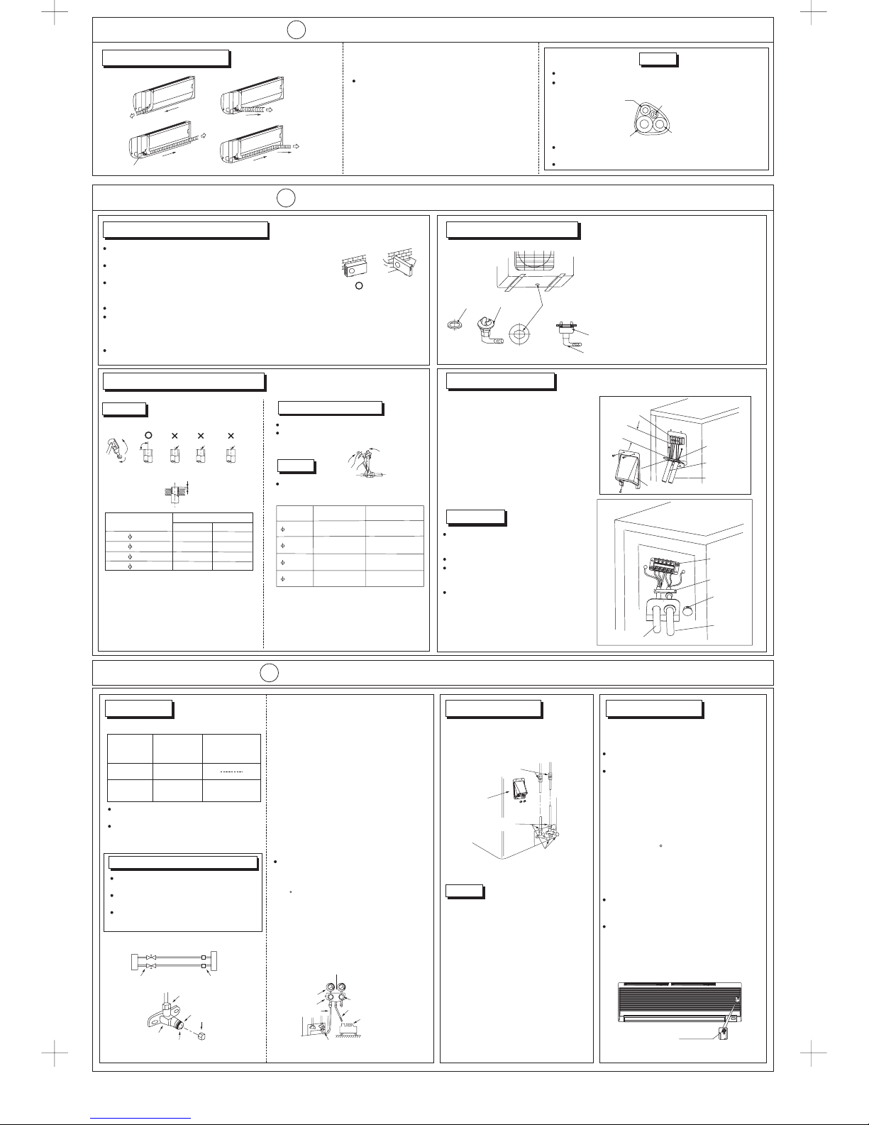
OUTDOOR UNIT INSTALLATION
2
AIR PURGE AND TEST OPERATION
3
1. Air Purge
Choose purgemethod from thetable:
Connective
pipe length
Less than 5m
5 ~ 10m
Air purging
method
Use vacuum
pump
Use vacuum
pump
Additional amount
of refrigerant to be
charged
When relocate the unit to an other place,
perform evacuation.using vacuum pump.
For the R407C/R410A refrigerant models,
make sure the refrigerant added into the air
conditioner is liquid form in any case.
Caution in Handing the Packed Valve
Open the valve stem until it hits against the
stopper. Do nottry toopen it further.
Securely tighten the valve stem cap with a
spanner orthe link.
Valvestem cap tighteningtorque.
Using theVacuum Pump
(For method of using a manifold valve, refer to its
operation manual)
Completely tighten the flare nuts A, B, C, D,
connect the manifold valve charge hose to a
charge port of the packed valve on the gas
pipe side.
Connect the charge hose connection to the
vacuum pump.
Fully openthe handle Loof themanifold valve.
Operate the vacuum pump to evacuate. After
starting evacuation, slightly loose theflare nut
of the packed valve on the gas pipe side and
check that theair is entering. (Operationnoise
of the vacuum pump changes and a
compound meterindicates 0 insteadof minus )
After the evacuation is complete, fully close
the handle Lo of the manifold valve and stop
the operationof the vacuumpump.
Make evacuationfor 15 minutesand more and
check thatthe compound meterindicates
-76cmHg.
Turn the stem of the packed valve B about
45 counterclockwise, securely tighten the
flare nutafter 6-7 seconds.
Disconnect the charge hose from the charge
connection of thepacked valve at the gas pipe
side.
Fully openthe packed valvesB and A.
Securely tightenthe cap ofthe packed valve.
O
1.
2.
3.
4.
5.
6.
7.
8.
Manifold valve
Compound meter
Pressure gauge
Indoor unit
check point
Outdoor unit
check point
A
B
C
D
Electrical box
2. Gas Leak Check
Make sure no gas from connections with
leak detector or soap water.
A: Lo packed valve B: Hi packed valve
C and D are ends of indoor unit connection.
Caution
3. Test Operation
(L-5)X30g
Outdoor unit Refrigerant Indoor unit
Flare nut
Stopper
Cap
Valve stem
Valve body
Packed valve
Half union
AC
D
B
Gas side
INDOOR UNIT INSTALLATION
1
6. Piping and Bandaging
Caution
Install thedrain hose atthe bottom of theconnective cable.
Reasonably and carefully arrange and bandage the piping in
case todamage the drainhose and connective piping.
-76cmHg
Packed valve at the gas pipe side
Charge hose
Handle Hi
Charge hose
Vacuum pump
Handle Lo
CS361-I2
2200019130
Manual switch
(See Tightening torque table above)
Liquid side
Right-hand piping
Slid Part cover
Left-hand piping
Rear-right piping
Rear-left piping
Connective piping
Connective cable
Drain hose
Tape
.
.
.
.
.
.
.
.
.
.
.
.
.
.
.
.
.
.
.
.
.
.
.
.
.
.
.
.
.
..
.
.
.
.
.
.
.
.
.
.
.
.
.
.
.
.
.
.
Strong
wind
X
1. Outdoor Installation Precaution
Install theoutdoor unit on arigid base to prevent increasing noise level
and vibration.
Determine the air outlet direction where the discharged air is not
blocked.
In thecase that theinstallation place is exposed tostrong wind such as
a seaside or high position, secure the normal fan operation byputting
the unitlengthwise along thewall or using adust or shield plates.
Specially inwindy area, installthe unit to preventthe admission ofwind.
If need suspending installation, the installation wall should be solid brick, concrete or the same
intensity construction, or actions to reinforce, damping, supporting should be taken. The
connection between bracket and wall, bracket and the air conditioner should be firm, stable and
reliable.
If needsuspending installation, theinstallation bracket shouldaccord with techniquerequirement in
the installationbracket diagram.
2. Drain Elbow Installation
Fit the seal into the drain elbow, then
insert the drainelbow into the basepan
hole of outdoor unit, rotate 90 to
securely assemble them. Connecting
the drain elbow with an extension drain
hose (Locally purchased), in case of
the water draining off the outdoor unit
during theheating mode
O
3. Refrigerant Piping Connection
1. Flaring
1. Cut a pipe with a pipe cutter.
2. Insert a flare nut into a pipe and flare the
pipe.
90
Oblique Rough-mess Burr
2. Tightening Connection
Align pipesto be connected.
Sufficiently tighten the flare nut with fingers,
and then tighten itwith a spanner and torque
wrench asshown.
Caution
4. Wiring Connection
A (mm)
Max.
Min.
Outlet diam.
(mm)
6.35
9.53
1.3
2
0.7
1.8
12.7
16
1.8
2.4
1.0
2.2
Excessive torque can break nut depending
on installationconditions.
Tightening
torque
Outlet
diam.
9.53mm
12.7mm
Additional tightening torque
3040(N.cm)
(310kgf.cm)
4900(N.cm)
(500kgf.cm)
3430(N.cm)
(350kgf.cm)
5390(N.cm)
(550kgf.cm)
16mm
7360(N.cm)
(750kgf.cm)
7850(N.cm)
(800kgf.cm)
6.35mm
1570(N.cm)
(160kgf.cm)
1960(N.cm)
(200kgf.cm)
Seal
Drain elbow
Base pan hole of
outdoor unit
Seal
Drain pipe
A
1.
Remove the cover control from the
unit by loosening the 3 screws.
2. Dismount caps on the conduit panel.
3. Temporarily mount the conduit tubes
(not included) on the conduit panel.
4. Properly connect both the power supply
and low voltage lines to the corresponding
terminals on the terminal block.
5. Ground the unit in accordance with local
codes.
6. Be sure to size each wire allowing several
inches longer than the required length for
wiring.
7. Use lock nuts to secure the conduit tubes.
G
G
Cover control
Over 40mm
Terminal block
Conduit panel
Connecting
cable
Power supply
cord
Outdoor unit
WARNING
Be sure to comply with local codes while
running the wire from the indoor unit to
the outdoor unit.
Every wire must be connected firmly.
No wire should be allowed to touch
refrigerant tubing, the compressor
or any moving parts.
Loose wiring may cause the terminal to
overheat or result in unit malfunction.
A fire hazard may also exit. Therefore,
be sure all wiring is tightly connected.
Note : Toprevent wires loosening or leaving the Cord
Clamp, please select proper cord diameter to fill the
holes on the cord clamp.
Cord clamp
Power supply
line
Toindoor unit
1
2(N)
S
L N
G
G
Cap
(remove)
Terminalblock
Perform test operation after completinggas
leak checkat the flarenut connections and
electrical safetycheck.
Check thatall tubing andwiring have been
properly connected.
Check thatthe gas andliquid side service
valves arefully open.
1. Connectthe power, press the ON/OFF
button onthe remote controller to turn the
unit on.
2. Usethe MODE buttonto select COOL,HEAT
(cooling &heating modles only), AUTO and
FAN to check if allthe functions workswell.
3. Whenthe amient temperatureis too low
(lower than17 C), theunit can notbe
contro lledby the remotecontroller to run
at coolingmode, manual operationcan be
taken. Manualoperation is usedonly when
the remotecontroller is disableor maintenance necessary.
Hold thepanel sides andlift the panelup to
an angleuntil it remainsfixed with a
clicking sound.
Press theManual control buttonto select
the AUTO orCOOL, the unitwill operate
under ForcedAUTO or COOL mode
(see UserManual for details).
4. The test operation should last about
30 minutes.
 Loading...