

Page 1

ESI-1002 Evaluation Board User Manual
Version 1.0
1. Introduction
This document describes the basic connection and use for ESI-1002 evaluation board.
2. Prerequisites
1. One 3.3V power supply
2. Input and Output SMA AC coupling caps capable of passing 10GBps signal
3. Installed ESI-1002 Configuration Utility/GUI
4. Use Total Phase Cheetah for SPI communication
3. Setting up ESI-1002 Evaluation board for Test
ESI-1002 EVALUATION USER MANUAL | ADVANCE INFORMATION – SUBJECT TO CHANGE | ENSPHERE CONFIDENTIAL
ENSPHERE SOLUTIONS, INC | 2900 LAKESIDE DRIVE, SUITE 228 | SANTA CLARA, CA 95054 | www.enspheresolutions.com
ESI-1002 Evaluation Board
Page 2
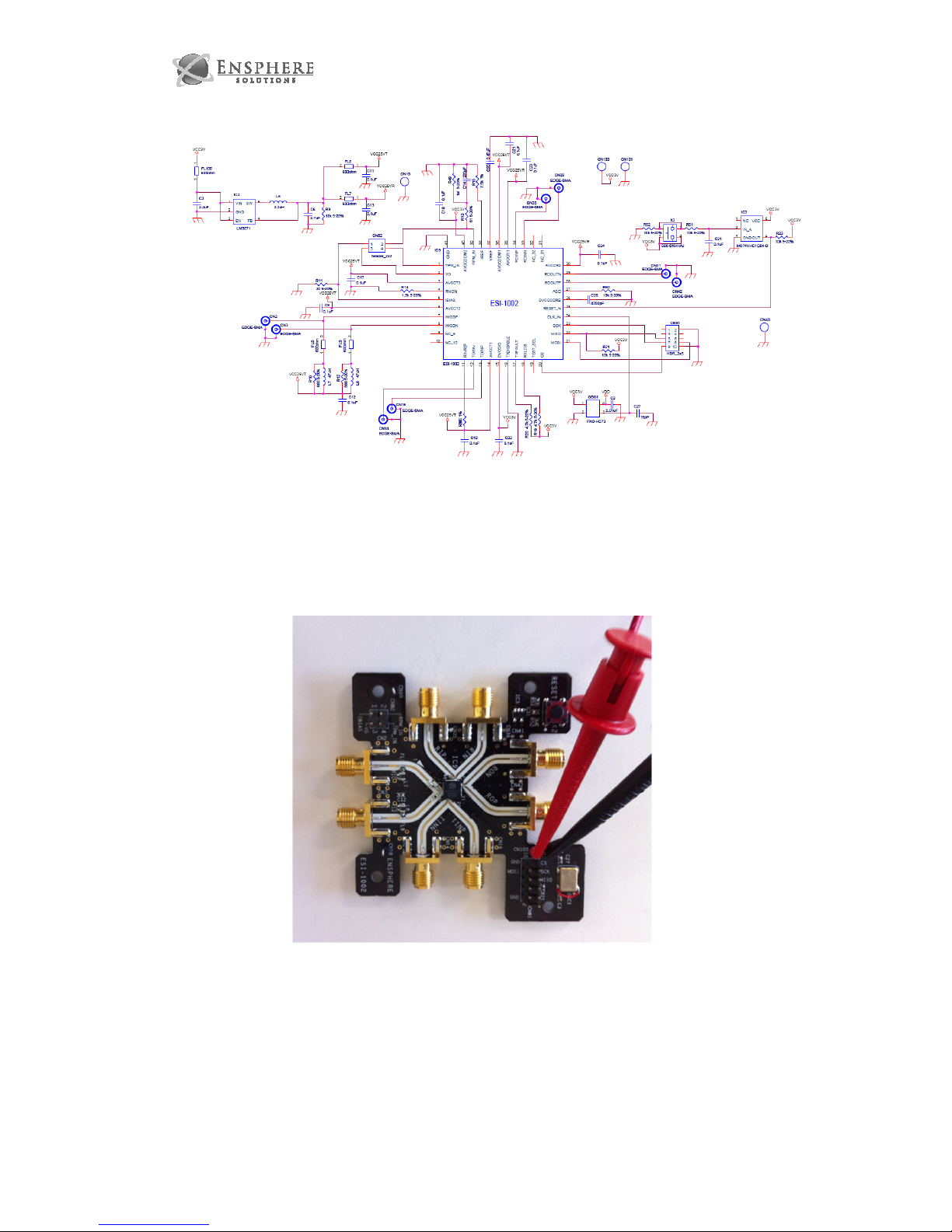
ESI-1002 Evaluation Board Schematic
1. Connect 3.3V power supply and ground to ESI board
Power Supply Connections
2. Connect Cheetah USB to SPI interface to evaluation board. Match pin 1 on Cheetah
interface with pin 1 on ESI-1002 Cheetah connector.
ESI-1002 EVALUATION USER MANUAL | ADVANCE INFORMATION – SUBJECT TO CHANGE | ENSPHERE CONFIDENTIAL
ENSPHERE SOLUTIONS, INC | 2900 LAKESIDE DRIVE, SUITE 228 | SANTA CLARA, CA 95054 | www.enspheresolutions.com
Page 3

3. Turn on 3.3V power supply.
4. Start GUI and Connect. Please see GUI user manual for GUI operation. Also see
datasheet for detailed register configuration information.
5. Configure ESI-1002 for test.
ESI-1002 EVALUATION USER MANUAL | ADVANCE INFORMATION – SUBJECT TO CHANGE | ENSPHERE CONFIDENTIAL
ENSPHERE SOLUTIONS, INC | 2900 LAKESIDE DRIVE, SUITE 228 | SANTA CLARA, CA 95054 | www.enspheresolutions.com
ESI-1002 Config Utility/GUI
Page 4
4. Applications
1. TX/VCSEL Driver Test:
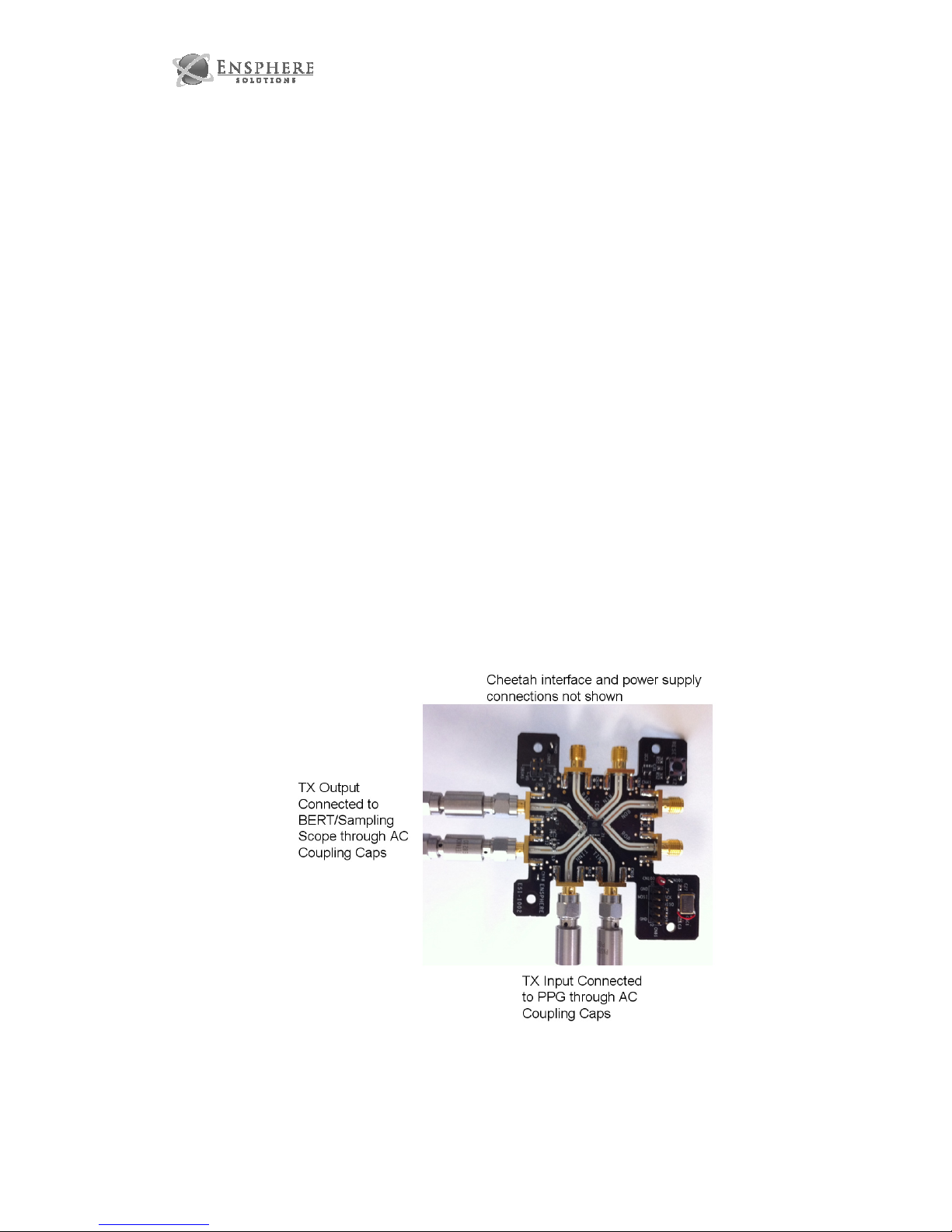
a. After setting up evaluation board for test connect TX input to PPG thru SMA
AC coupling caps and TX output to load.
b. Load TX driving script and observe output on scope.
c. IMOD amplitude control
d. TX waveform control
i. Adjust crossing percentage of waveform by changing Pulse width
control
ii. Adjust Pre-driver current.
iii. Negative impedance control in TX input
iv. Adjust IMOD peaking height. Please check IMOD Peaking enable
control box to activate.
v. Adjust IMOD compensation. Please check IMOD Compensating
control enable control box to activate.
vi. Adjust IMOD peaking width. Please check IMOD Peaking enable
control box to activate.
2. RX Test:
ESI-1002 EVALUATION USER MANUAL | ADVANCE INFORMATION – SUBJECT TO CHANGE | ENSPHERE CONFIDENTIAL
ENSPHERE SOLUTIONS, INC | 2900 LAKESIDE DRIVE, SUITE 228 | SANTA CLARA, CA 95054 | www.enspheresolutions.com
Page 5
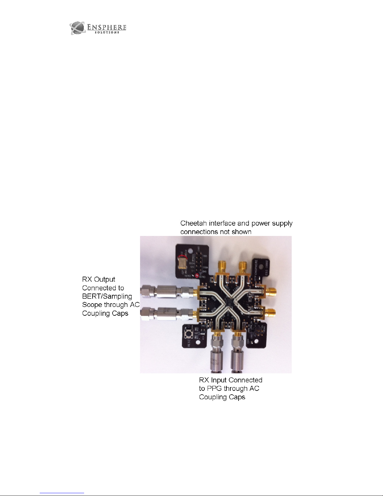
a. After setting up evaluation board for test connect RX input to PPG thru SMA
AC coupling caps and RX output to load.
b. Load RX driving script and observe output on scope.
c. RX waveform control
i. Adjust Preemphasis magnitude. Please check Preemphasis enable
control box to activate.
ii. Adjust Preemphasis phase. Please check Preemphasis enable
control box to activate.
iii. Activate LNB by unchecking LNB buffer power down control. Do not
activate LNB while LIA is active.
iv. Activate LIA by unchecking LIA buffer power down control. Do not
activate LIA while LNB is active
v.
3. Gate Voltage DAC test
a. After setting up evaluation board for test connect VG pin to load
ESI-1002 EVALUATION USER MANUAL | ADVANCE INFORMATION – SUBJECT TO CHANGE | ENSPHERE CONFIDENTIAL
ENSPHERE SOLUTIONS, INC | 2900 LAKESIDE DRIVE, SUITE 228 | SANTA CLARA, CA 95054 | www.enspheresolutions.com
Page 6

b. Run script to activate all DACs.
c. Modify DAC setting value for VG to modify VG voltage
4. Temperature Sensor Reading Test
a. Set up evaluation board for test.
b. Run script for Temp Sensor reading.
c. Observe temperature reading in GUI.
5. Run any generic test by setting registers manually. If there is a particular test or
setting you would like to run please contact Ensphere’s applications team as they
can advise as to how to successfully run any test. Other possible tests you may
consider:
a. Receive Power Monitoring
b. Bias current programming
c. Set Alarms for Transmit power monitor, Power supply monitor, Receive
Power monitor, Temperature Monitor, Bias current Monitor
d. Set Warnings for Transmit power monitor, Power supply monitor, Receive
Power monitor, Temperature Monitor, Bias current Monitor
e. Measure bias current monitor voltage
ESI-1002 EVALUATION USER MANUAL | ADVANCE INFORMATION – SUBJECT TO CHANGE | ENSPHERE CONFIDENTIAL
ENSPHERE SOLUTIONS, INC | 2900 LAKESIDE DRIVE, SUITE 228 | SANTA CLARA, CA 95054 | www.enspheresolutions.com
Page 7

Notice
Information furnished is believed to be accurate and reliable. However, ALL
ENSPHERE DESIGN SPECIFICATIONS, FILES, DRAWINGS,
DIAGNOSTICS, LISTS, AND OTHER DOCUMENTS (TOGETHER AND
SEPARATELY, “MATERIALS”) ARE PROVIDED “AS IS.” ENSPHERE
MAKES NO WARRANTIES, EXPRESSED, IMPLIED, STATUTORY, OR
OTHERWISE WITH RESPECT TO THE QUALITY AND ACCURACY OF
THESE MATERIALS, AND EXPRESSLY DISCLAIMS ALL IMPLIED
WARRANTIES OF NONINFRINGEMENT, MERCHANTABILITY, AND
FITNESS FOR A PARTICULAR PURPOSE.
Ensphere Solutions Incorporated assumes no responsibility for the
consequences of use of such information or for any infringement of patents
or other rights of third parties that may result from its use. N license is
granted by implication or otherwise under any patent or patent rights of
Ensphere Solutions Incorporated. Specifications mentioned in this
publication are subject to change without notice. This publication
supersedes and replaces all information previously provided.
Trademarks
Ensphere and the Ensphere logo are trademarks or registered trademarks of
Ensphere Solutions Incorporated in the U.S. and other countries. Other
company and product names may be trademarks of the respective
companies with which they are associated.
Copyright
© 2009, 2010 Ensphere Solutions Incorporated. All rights reserved.
ESI-1002 EVALUATION USER MANUAL | ADVANCE INFORMATION – SUBJECT TO CHANGE | ENSPHERE CONFIDENTIAL
ENSPHERE SOLUTIONS, INC | 2900 LAKESIDE DRIVE, SUITE 228 | SANTA CLARA, CA 95054 | www.enspheresolutions.com
 Loading...