

ENSONIQ OEX-6sr Operation Manual

Output Expander
OEX-6sr

OEX-6sr
Operation Manual
What is the OEX-6sr Output Expander?
The
OEX6sr
is a multi-function digital device that adds six
individual outputs, or three additional pairs of stereo outputs to an
ASR- 10, ASR-88, or EPS- 16 PLUS keyboard, enhancing the
capabilities and flexibility of the ASR/EPS-16 PLUS.
The power of the OEX-6sr Output Expander lies in its unique
configuration: six individual outputs or three stereo pairs (AUX 1,
AUX 2, AUX 3). The addition of these outputs allows you to
route separate signals for independent processing, or isolate parts
for click or monitoring references. Even individual WaveSamples
within an instrument (for instance, the snare and kick drum from a
drum kit) can be sent to different outputs for discrete external
effects processing (such as with the ENSONIQ DP/4+ Parallel
Effects Processor). The design of this product resulted from
customer requests for a multi-purpose output device that could be
configured with stereo outputs and/or individual outputs. As with
any product, getting to know its operation will help to increase
your productivity and enhance the performance and expression of
your music.
IMPORTANT! Because the OEX-6sr is a digital device, no audio
signal passes through the connector cable from the ASR/EPS-16
PLUS to the OEX-6sr.
Do not connect this cable to any other
device that uses a similar connector (such as a Macintosh), as
this will damage both units and void their warranties.
Important points about the OEX-6sr
l
Never connect the OEX-6sr while the power to the
ASIUEPS-16 PLUS is on. This will damage both units
and void their warranties.
l
The signals sent to AUX 1, AUX 2, and AUX 3 on the
OEX-6sr are dry; these outputs do not pass signals with
effects. The wet signal is only present at the Main
Audio Outputs.
l
The AUX 1, AUX 2, and AUX 3 outputs on the OEX-
6sr are always active when the
OEX-6sr
is connected;
see the signal flow diagram.
l
The Outputs on the OEX-6sr are not affected by the
ASR/EPS- 16 PLUS master Volume Slider.
l
Assigning of sounds to the
OEX-6sr
can be handled two
I
OEX-6sr Operation Manual
ways; at the WaveSample level or at the track level.
Setting-up the OEX-6sr
Although you can set-up your OEX-6sr any way you like, we
suggest using one of these practical mounting methods:
Rubber Feet Only Mount
Here’s what you’ll need to get started:
1)
2)
l OEX-6sr Output Expander
l
Six foot connection cable (cable lengths of 10 feet or
longer may not give optimal results, and are not
recommended by ENSONIQ)
l
Four rubber feet (included)
Apply rubber feet to the bottom of the
OEX-6sr.
Place the OEX-6sr in the
position of your choice,
such as the recess over the
ASR/EPS-
16 PLUS logo,
or on the floor beneath
your keyboard stand.
Velcro Only Mount
Here’s what you’ll need to get
started:
1)
2)
3)
l OEX-6sr Output
Expander
l
Six foot connection cable (cable lengths of 10 feet or
longer may not give optimal results, and are not
recommended by ENSONIQ)
l
Two strips of adhesive velcro (included)
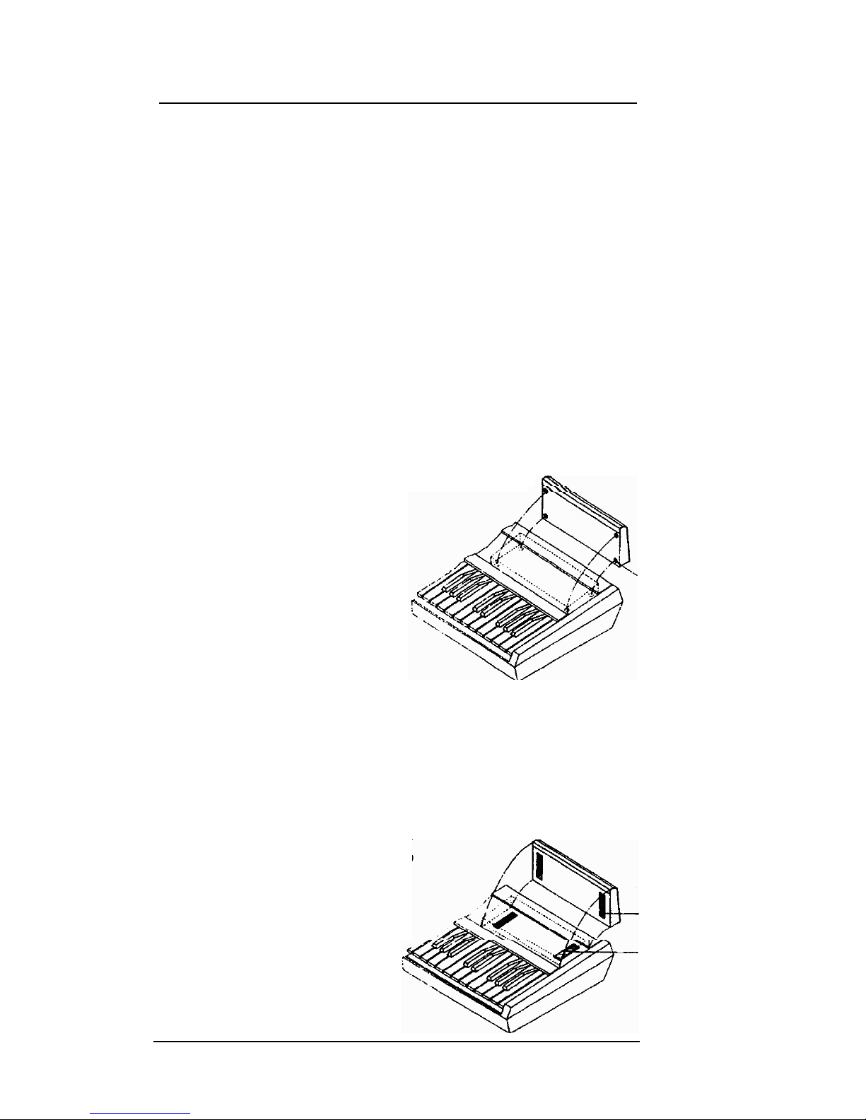
Position the
OEX-6sr
on the top
right corner of the
ASR/EPS-16
PLUS. It fits comfortably in
the recess directly over the
ASR/EPS-16 PLUS logo.
Mark the position with
masking tape (not included).
Place the “furry” side of the
two adhesive velcro strips
2
OEX-6sr
Operation Manual
(included) in the position marked by your masking tape.
Remember to remove the masking tape and discard. Then
place the “hook” side of the velcro strips on the bottom of
the OEX-6sr. Use your thumb to apply pressure to all
velcro strips to ensure a secure fit. Keep in mind, that it
could be difficult to remove the velcro from the front panel
of the ASR/EPS- 16 PLUS at a later time.
You should now be able to place your OEX-6sr on the velcro strips
and have it remain in position. We suggest cleaning the velcro
strips periodically to maintain a secure fit.
Rubber Feet and Velcro Mount
Here’s what you’ll need to get started:
1)
2)
3)
l OEX-6sr Output Expander
l
Six foot connection cable (cable lengths of 10 feet or
longer may not give optimal results, and are not
recommended by ENSONIQ)
l
Four rubber feet (included)
l
Two strips of adhesive velcro (included)
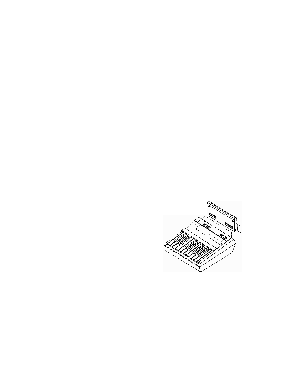
It is also possible to mount the
OEX-6sr with a combination of
rubber feet and velcro. Apply
the rubber feet to the bottom
front of the
OEX-6sr
as shown
in the illustration.
Mark a location on the upper
right hand lip of the
ASR/
EPS-16 PLUS. This is
where your velcro will be
positioned (the velcro is
mounted horizontally in this application).
Place the “furry” side of the two adhesive velcro strips
(included) in the position marked by the masking tape.
Remember to remove the masking tape and discard. Then
place the “hook” side of the two velcro strips on the bottom
of the OEX-6sr. Use your thumb to apply pressure to all
velcro strips to ensure a secure fit.
3
OEX-6sr
Operation Manual
Single Space 19” Rack Shelf Mount
Here’s what you’ll need to get started:
l
OEX-6sr
Output Expander
l
Six foot connection cable (cable lengths of 10 feet or
longer may not give optimal results, and are not
recommended by
ENSONIQ)
l Two 6-32 x
3/8
SEM machine screws (included)
l Optional 19” rack mount shelf. The following universal
rack shelves are compatible with the OEX-6sr:
l MIDDLE ATLANTIC PRODUCTS model #UTR- 1
For the dealer nearest you, contact:
MIDDLE ATLANTIC PRODUCTS, INC.
P.O. Box 29
Riverdale, NJ 07457-0029
USA
telephone: (201) 839-1011 (New Jersey)
(805) 529-6104 (California)
l
RAXXESS model #UNS- 1
For the dealer nearest you, contact:
RAXXESS Metalsmiths
Precision Industry Specialties
P.O. Box 417
Riverside Station
Paterson, NJ 07544-04 17
USA
telephone: (800) 398-7299
(201) 523-1425

OEX-6sr
Operation Manual
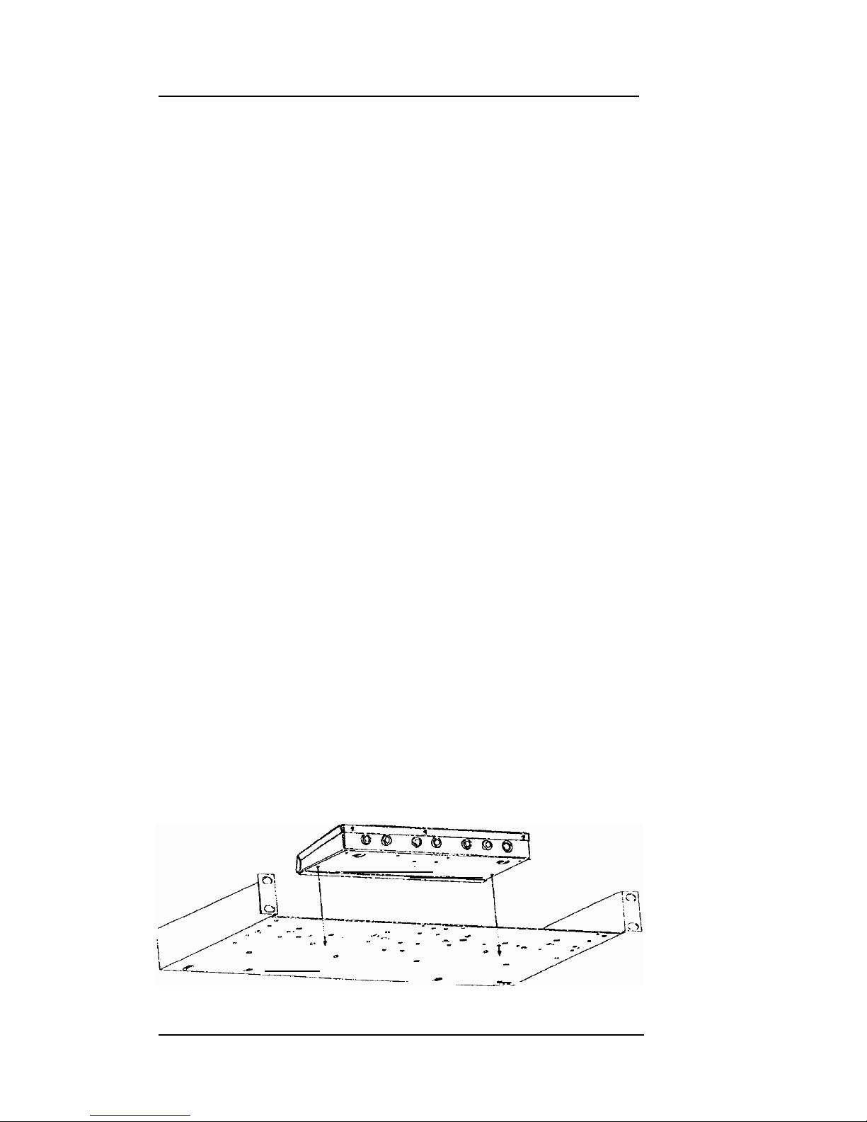
1) Position the OEX-6sr on the optional rack shelf, aligning the
two outer holes on the bottom of the
OEX-6sr
with a pair of
holes on the rack shelf. The OEX-6sr can be mounted
facing either way, but we suggest facing the Output jacks of
the OEX-6sr towards the front of the rack shelf. This will
aid in quick changes for recording purposes.
2) Attach the OEX-6sr to the rack shelf using two (included)
screws.
3)
Once the
OEX-6sr
is attached to the rack shelf, you can
mount the shelf into a rack mount housing.
Mic Flange Mount
Here’s what you’ll need to get started:
1)
2)
l OEX-6sr Output Expander
l
Six foot connection cable (cable lengths of 10 feet or
longer may not give optimal results, and are not
recommended by ENSONIQ)
l Three 6-32 x
3/8
SEM machine screws (included)
l
Optional microphone stand hardware
l Optional flange. The following 5/8”-27 F. microphone
stand mounting flanges are compatible with the
OEX-6sr:
l
ATLAS/SOUNDOLIER
models #AD- 11 B (chrome)
and #AD-
11
BE (ebony)
For the dealer nearest you, contact:
ATLAS/SOUNDOLIER
Atapco Security & Communications Group
1859 Intertech Drive
Fenton, MO 63026
USA
telephone: (800) 876-7337
(3 14) 349-3 110
Turn the OEX-6sr upside
OEX-6sr can be positioned
in a variety of ways. One
5

OEX-6sr
Operation Manual
of the simplest mountings would be to remove the
microphone holder from a mic stand and attach the
OEX-6sr
(flange) to the stand.
Connecting the
OEX-6sr
Once the
OEX-6sr
has been mounted, connect the multiplexed
input of the OEX-6sr to the Output Expander jack on the
ASR/
EPS-16 PLUS, with the enclosed connection cable.
Important! Power to the
ASR/EPS-16
PLUS must be off prior
to connecting or disconnecting the OEX-6sr. Connecting the
OEX-6sr with the power on can cause damage to the
ASR/
EPS-16 PLUS and/or the OEX-6sr itself.
Understanding the ASR-10/ASR-88 Output Busses
A sound in the ASR can be assigned to one of six stereo sends,
which we call busses. An understanding of how these busses are
routed to the OEX-6sr, as well as to the ASR Main Audio Outputs,
is crucial to your getting the most out of the OEX-6sr. The signal
flow of the six output busses is shown in the diagram on the facing
page. We suggest you study it carefully, as it can answer many of
your questions regarding what signal will be routed where.
When the PAN parameter is set to -99, the sound will be sent only
to the left signal of the bus. When the PAN parameter is set to
+99,
the sound will be sent only to the right signal of the bus. This
is how you can create six individual outputs.
The six output busses are as follows:
* BUS 1,2,3
Sounds assigned to these busses will always be
routed to the
ASR’s
internal effects processor and on
to the Main Audio Outputs.
l
AUX
1,2,3
Sounds assigned to these busses will always be
routed to the output labeled AUX 1, 2, or 3 on the
OEX-6sr,
and only to that output. Sounds assigned to
AUX 1,2, or 3 will always be dry, with no effects
processing.
6
 Loading...