

Page 1

6 4 V o i c e E x p a n d a b l e S y n t h
M u s i c i a n ’ s M a n u a l
V e r s i o n 1 . 5 0
Page 2

M R - R a c k M u s i c i a n ’ s M a n u a l :
Documentation Team: Robby Berman, Jonathan Coulton, Tom Tracy, Bill Whipple
Copyright © 1995, 1996
ENSONIQ® Corp
155 Great Valley Parkway
Box 3035
Malvern, PA 19355-0735
USA
Printed in U.S.A.
All Rights Reserved
Please record the following information:
Your Authorized ENSONIQ Dealer:___________________________ Phone:_______________
Your Dealer Sales Representative:_________________________________________________
Serial Number of Unit:___________________________ Date of Purchase:_________________
Your Authorized ENSONIQ Dealer is your primary source for service and support. The above information will
be helpful in communicating with your Authorized ENSONIQ Dealer, and provide necessary information
should you need to contact ENSONIQ Customer Service. If you have any questions concerning the use of this
unit, please contact your Authorized ENSONIQ Dealer first. For additional technical support, or to find the
name of the nearest Authorized ENSONIQ Repair Station, call ENSONIQ Customer Service at (610) 647-3930
Monday through Friday 9:30 AM to 12:15 PM and 1:15 PM to 6:30 PM Eastern Time. Between 1:15 PM and
5:00 PM we experience our heaviest call load. During these times, there may be delays in answering your
call.
You can utilize ENSONIQ’s Automatic Fax Retrieval System to obtain further information about your MRRack and other ENSONIQ products. The Fax Retrieval System is available 24 hours a day at (800) 257-1439.
If you’re connected to the Internet, visit ENSONIQ’s World Wide Web site at www.ensoniq.com for more
information on the MR-Rack and other ENSONIQ products. CompuServe subscribers can also find ENSONIQ
at GO ENSONIQ.
This manual is copyrighted and all rights are reserved by ENSONIQ Corp. This document may not, in whole
or in part, be copied, photocopied, reproduced, translated, or reduced to any electronic medium or machine
readable form without prior written consent from ENSONIQ Corp. The MR-Rack software/firmware is
copyrighted and all rights are reserved by ENSONIQ Corp. Although every effort has been made to ensure the
accuracy of the text and illustrations in this manual, no guarantee is made or implied in this regard.
IMPORTANT:
Note: This equipment has been designed and found to comply with the limits for a Class B digital device,
pursuant to Part 15 of the FCC rules. These limits are designed to provide reasonable protection against
harmful interference in a residential installation. This equipment generates, uses and can radiate radio
frequency energy and, if not installed and used in accordance with the instructions, may cause harmful
interference to radio communications. However, there is no guarantee that interference will not occur in a
particular installation. If this equipment does cause harmful interference to radio or television reception,
which can be determined by turning the equipment off and on, the user is encouraged to try to correct the
interference by one or more of the following measures:
* Reorient or relocate the receiving antenna.
* Increase the separation between the equipment and receiver.
* Connect the equipment into an outlet on a circuit different from that to which the receiver is connected.
* Consult the dealer or an experienced radio/TV technician for help.
Changes or modifications to the product not expressly approved by ENSONIQ could void the user’s FCC
authority to operate the equipment.
CAUTION! Danger of explosion if battery is incorrectly replaced. Replace only with the same or
equivalent type recommended by the manufacturer. Discard used batteries according to
manufacturer's instructions.
In order to fulfill warranty requirements, the MR-Rack should be serviced only by an Authorized ENSONIQ
Repair Station. The ENSONIQ serial number label must appear on the outside of the unit, or the ENSONIQ
warranty is void.
• ENSONIQ, MR-Rack are trademarks of ENSONIQ Corp.
Part # 9310 0191 01 - E Model # MM-130
Page 3

I n s t a n t M R - R a c k !
The following is not a description of the only way to use the MR-Rack—it simply
gets you down to the business of making music immediately. It doesn’t explain
any of the whys and wherefores or discuss the many creative possibilities of the
MR-Rack. The rest of this manual, however, does.
To Get Started
1. Turn the MR-Rack’s front-panel Volume knob down all the way.
2. Connect the MR-Rack’s Main Outs (the two jacks on the right when viewing
the MR-Rack from the rear) to a mixer or stereo keyboard amplifier set to
conservative levels, or connect a pair of stereo headphones to the MR-Rack’s
front-panel Phones jack.
3. Connect the MIDI Out of your sequencer/interface/controller, etc. to the MRRack’s MIDI In.
4. Power up your sequencer/interface/controller, etc.
5. Connect the MR-Rack to a grounded AC outlet, using its supplied AC cord.
6. Power up the MR-Rack.
7. Bring up the MR-Rack’s Volume knob about halfway—you can adjust it
later, after you start playing some music. Your display looks something like
this:
pt01:§01 ROM:004:030
DEMO-SND: Dense Mist
You’re seeing the Sound selected for Part 01. The MR-Rack contains 16 Parts,
which are currently set to MIDI channels 1-16. Try the Sound out, if you like, by
setting your MIDI controller to transmit on MIDI channel 1.
To Change the Sound on This Part
1. Turn the Sound Type knob clockwise or counter-clockwise to select the type
of Sound you want.
2. Turn the Sound Name knob in either direction to choose a particular Sound.
To Get to the Other 15 Parts (MIDI Channels 2-16)
• Press one of the Select Parts buttons to select another Part.
The number of the Part you’re working on will be shown in the upper left-
hand part of the display.
To Mute a Part
• Select the Part you want to silence and press the Mute button.
The button’s red LED will light, and the word “mute” will be displayed.
Page 4

T e m p e r a t u r e G u i d e l i n e s
The MR-Rack contains a substantial
amount of computerized and
electronic circuitry that can be
susceptible to damage when exposed
to extreme temperature changes.
When the MR-Rack is brought inside
after sitting in a cold climate (i.e.,
the back seat of your car),
condensation builds up on the
internal circuitry in much the same
way a pair of glasses fogs up when
you come inside on a cold day. If the
unit is powered up as this
condensation occurs, components
can short out or be damaged.
Excessively high temperatures also
pose a threat to the unit, stressing
both the internal circuits as well as
the case. With this in mind, it is
highly advisable to follow these
precautions when storing, mounting
and setting up your MR-Rack:
• Avoid leaving the MR-Rack in
temperatures of less than 50
degrees Fahrenheit or more than
100 degrees Fahrenheit.
• When bringing the MR-Rack
indoors after travel, allow the
unit at least 20 minutes to reach
room temperature before
powering up. In the case of
excessive outdoor temperatures
(below 50 degrees Fahrenheit or
above 100 degrees Fahrenheit),
allow an hour or more before
power up.
• Avoid leaving the MR-Rack
inside a vehicle exposed to direct
sunlight.
C l e a n U p a n d M a i n t e n a n c e
Clean the exterior of your MR-Rack
with a soft, lint-free, dry (or slightly
damp) cloth. You can use a slightly
dampened cloth (with a mild neutral
detergent) to remove stubborn dirt,
but make sure that the MR-Rack is
thoroughly dry before turning on
the power. Never use alcohol,
benzene, volatile cleaners, solvents,
abrasives, polish or rubbing
compounds.
R a c k M o u n t I n s t r u c t i o n s
The MR-Rack can be rack mounted
in a standard 19” audio rack:
• The MR-Rack occupies one
standard rack space (1 3/4”). We
recommend the use of nylon
washers when rack mounting
any unit. This will protect the
faceplate from any damage.
• If you’re using only two screws
to mount your unit into a rack
space (we don’t recommend this),
we suggest that you support the
bottom of the unit.
• You may want to install the MRRack into a rack using quickrelease screws. Quick release
screws don’t require a
screwdriver, so it’s easy to move
things in and out of a rack. Four
posts are screwed into the rack
holes, the unit goes over the
posts, and then knurled nuts are
screwed on by hand.
Page 5
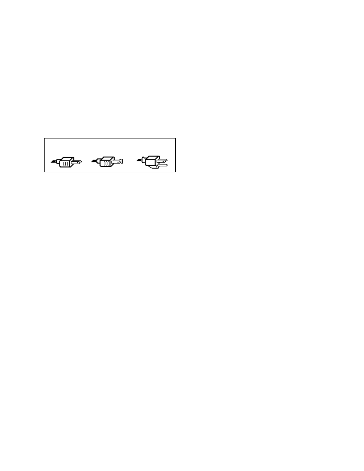
P o l a r i z a t i o n a n d G r o u n d i n g
Like many modern electrical devices,
your ENSONIQ product has a threeprong power cord with earth ground
to ensure safe operation. Some
products have power cords with
only two prongs and no earth
ground. To ensure safe operation,
modern products with two-prong
power cords have polarized plugs
which can only be inserted into an
outlet the proper way.
Three-prong
PolarizedNon-polarized
Some products, such as older guitar
amplifiers, do not have polarized
plugs and can be connected to an
outlet incorrectly. This may result in
dangerous high voltages on the
audio connections, which could
cause you physical harm or damage
any properly grounded equipment to
which they are connected, such as
your ENSONIQ product.
To avoid shock hazards or
equipment damage, we recommend
the following precautions:
• If you own equipment with twopronged power cords, check to
see if they are polarized or nonpolarized. You might consider
having an authorized repair
station change any nonpolarized plugs on your
equipment to polarized plugs to
avoid future problems.
• Exercise caution when using
extension cords or plug adapters.
Proper polarization should
always be maintained from the
outlet to the plug. The use of
polarized extension cords and
adapters is the easiest way to
maintain proper polarity.
• Whenever possible, connect all
products with grounded power
cords to the same outlet ground.
This will ensure a common
ground level to prevent
with earth ground
equipment damage and minimize
hum in the audio output.
AC outlet testers are available from
many electronic supply and
hardware stores. These can be used
to check for proper polarity of outlets
and cords.
A C L i n e C o n d i t i o n i n g
As with any computer device, the
MR-Rack is sensitive to sharp peaks
and drops in the AC line voltage.
Lightning strikes, power drops, or
sudden and erratic surges in the AC
line voltage can scramble the
internal memory, and in some cases,
damage the unit’s hardware. Here
are a few suggestions to help guard
against such occurrences:
• A Surge/Spike Suppressor. The
cheaper of the options, a
surge/spike suppressor absorbs
surges and protects your gear
from all but the most severe
over-voltage conditions. You can
get multi-outlet power strips
with built-in surge/spike
suppressors for little more than
the cost of unprotected power
strips, so using one is a good
investment for all your electronic
equipment.
• A Line Conditioner. This is the
best, but by far the more
expensive way to protect your
gear. In addition to protecting
against surges and spikes, a line
conditioner guards the
equipment against excessively
high or low line voltages. If you
use the MR-Rack in lots of
different locations with varying
or unknown AC line conditions,
you might consider investing in
a line conditioner.
Page 6

Table of Contents
Instant MR-Rack!
Chapter 1—Welcome
Welcome!....................................................................................................................1
Getting Ready to Listen.............................................................................................1
Powering Up...............................................................................................................1
Choosing Sounds......................................................................................................2
Understanding the MR-Rack......................................................................................3
Sounds....................................................................................................................3
Parts........................................................................................................................3
Performances...........................................................................................................4
Choosing Performances on the MR-Rack............................................................4
Effects......................................................................................................................4
Drum Kits................................................................................................................5
Staks.......................................................................................................................5
SoundFinder™........................................................................................................5
How the MR-Rack’s Memory Works........................................................................5
ROM and RAM........................................................................................................6
ROM Cards..............................................................................................................6
SRAM Cards............................................................................................................6
EXP Series Wave Expansion Boards.......................................................................6
The MR-Rack Display.............................................................................................6
Playing the MR-Rack Demo.......................................................................................7
To Play the MR-Rack Main Demo........................................................................7
Playing Other Demos.................................................................................................7
To Play Other MR-Rack Demos...........................................................................7
Other Points of Interest.............................................................................................8
All Notes Off............................................................................................................8
The MR-Rack’s Battery...........................................................................................8
Battery Low Warning...........................................................................................8
If You Experience Odd Behavior.............................................................................9
To Perform A Soft Reset.......................................................................................9
To Perform a Standard Reinitialization..............................................................9
To Perform a Hard Reinitialization......................................................................9
Available Options for Your MR-Rack........................................................................10
Need More Help?.........................................................................................................10
Table of Contents
Chapter 2—Connections
Introduction...............................................................................................................13
To Get Ready..........................................................................................................13
What Connections Need to be Made?.....................................................................13
Making MIDI Connections.........................................................................................13
Using the MR-Rack with a Controller.....................................................................14
What You’ll Need.................................................................................................14
To Connect the MR-Rack.....................................................................................14
Connecting the Rest of Your System..................................................................14
Using the MR-Rack with a Workstation.................................................................14
What You’ll Need.................................................................................................14
To Connect the MR-Rack.....................................................................................15
Connecting the Rest of Your System..................................................................15
Using the MR-Rack with a Stand-Alone Sequencer...............................................15
What You’ll Need.................................................................................................15
To Connect the MR-Rack.....................................................................................16
Connecting the Rest of Your System..................................................................16
Editing Sounds with the MR-Rack and a Computer..............................................16
ENSONIQ MR-Rack Musician’s Manual Table of Contents — 1
Page 7

Table of Contents
Sequencing with the MR-Rack, a Computer and a Controller..............................17
Using the MR-Rack with a Computer, Controller and MIDI Merger.......................18
Using the MR-Rack with a Computer, Controller and MIDI Patchbay..................19
Making Audio Connections.......................................................................................21
Making the Power Connection..................................................................................22
Powering Up............................................................................................................22
Confirming Your MIDI Connection...........................................................................23
To Verify that the MR-Rack is Receiving MIDI.......................................................23
Setting Volume Levels...............................................................................................24
Using the MR-Rack for General MIDI Music..............................................................25
Moving On.................................................................................................................25
What You’ll Need.................................................................................................16
To Connect the MR-Rack....................................................................................16
Connecting the Rest of Your System..................................................................17
What You’ll Need.................................................................................................17
To Connect the MR-Rack....................................................................................17
Connecting the Rest of Your System..................................................................18
What You’ll Need.................................................................................................18
To Connect the MR-Rack....................................................................................18
Connecting the Rest of Your System..................................................................19
What You’ll Need.................................................................................................20
To Make Your MIDI Patchbay Connections........................................................20
Connecting the Rest of Your System..................................................................20
To Connect the MR-Rack’s AC Power..................................................................22
To Confirm that the MR-Rack is Responding to MIDI........................................24
Chapter 3—Personalizing Your System
Using the Global Pitch Bend Settings.......................................................................26
Global Pitch Bend Up and Down...........................................................................27
To Determine the Global Pitch Bend Up Range..................................................27
To Determine the Global Pitch Bend Down Range.............................................27
Setting the Global Pitch Bend Mode......................................................................27
To Determine the Global Pitch Bend’s Behavior................................................28
Retuning the MR-Rack..............................................................................................28
Fine Tuning the MR-Rack......................................................................................28
To Fine Tune the MR-Rack.................................................................................28
Using Pitch Tables..................................................................................................28
To Assign a Global Pitch Table...........................................................................29
To Assign a Part to a Special Pitch Table...........................................................29
Synchronizing the MR-Rack to MIDI........................................................................29
To Set the Global Tempo Clock as the Timing Reference...................................29
To Sync the MR-Rack’s Clock to an External MIDI Device.................................29
To Set the Global Clock Tempo...........................................................................30
Protecting Part Settings.............................................................................................30
To Protect Part Parameter Settings When New Sounds are Selected.................30
To Protect Part Parameters from Reset All Controllers MIDI Messages...............31
To Allow the Selection of New Sounds to Reset Part Parameter Settings..........31
To Allow Reset All Controllers Messages to Reset Part Parameter Settings.......31
Letting the MR-Rack Pick Your Chorus or Reverb....................................................31
To Let the MR-Rack Automatically Pick a Sound’s Chorus or Reverb...............32
To Protect Part Effect Bus Settings When a New Sound is Selected..................32
Using the MR-Rack’s Four Outputs..........................................................................32
Routing Sounds to Specific Outputs.....................................................................33
To Send a Part, Its Sound and Effect to the Desired Outputs...........................33
To Send a Part and Its Dry Sound to the Desired Outputs...............................33
Determining the Behavior of the Aux Outs...........................................................34
To Enable Automatic Aux Out Routing Based on Cabling................................34
To Use the Aux Outs with Permanently Connected Outputs...........................34
Auditioning Sounds on the MR-Rack.......................................................................35
To Set What’s Heard When the Audition Button is Pressed..............................35
Table of Contents — 2 ENSONIQ MR-Rack Musician’s Manual
Page 8

Table of Contents
Waking up..................................................................................................................35
To Set How the MR-Rack Will Wake Up .............................................................36
Protecting the MR-Rack’s Memory.............................................................................36
To Enable the Write Protect Prompt....................................................................36
To Disable the Write Protect Prompt...................................................................36
Setting the Stak MIDI Channel.................................................................................37
To Set the Stak MIDI Channel............................................................................37
Adjusting Stak Coherence.........................................................................................37
To Perfectly Synchronize the Start of All Notes in a Stak..................................37
To Allow All Notes in a Stak to Start Normally...................................................38
Using MIDI Program Changes....................................................................................38
Changing Performances Via MIDI...........................................................................38
To Select New Performances With MIDI Program Changes.................................38
To Disable the Selection of Performances By Program Changes........................39
Setting the Global Reception of MIDI Bank Selects and Program Changes...........39
To Enable Reception of Bank Selects and Program Changes..............................39
To Disable Reception of Bank Selects and Program Changes.............................39
Responding to MIDI “Panic” Messages.......................................................................40
Setting the MR-Rack’s Response to Reset All Controllers MIDI Messages................40
To Set the Response to Reset All Controllers Messages......................................40
Setting the MR-Rack’s Response to All Notes Off MIDI Messages.............................40
To Set the MR-Rack’s Response to All Notes Off Messages.................................40
Using MIDI SysEx.......................................................................................................41
Enabling and Disabling System Exclusive Communication..................................41
To Enable or Disable SysEx Communication.....................................................41
Using SysEx Device IDs.............................................................................................41
To Set the MR-Rack’s SysEx Device ID Number..................................................41
Setting Up New Real-Time Controllers......................................................................42
To Set Up the Four System Controllers..............................................................42
Learning How Much RAM is Available for New Sounds...........................................43
To Find Out How Much Free Memory (RAM) is Available in the MR-Rack........43
Learning the Number of Banks on a Data Card........................................................43
To Learn How Many Banks are on the Currently Installed Card.......................44
Identifying Installed Wave Expansion Boards..........................................................44
To Identify an Installed Expansion Board..........................................................44
Using the MR-Rack to Play General MIDI Music.......................................................45
To Use the MR-Rack as a General MIDI Sound Module......................................45
To Set the MR-Rack to Power Up Ready for General MIDI Music.......................45
To Reset the MR-Rack for Use with Non-General MIDI Music............................46
MR-Rack General MIDI Details for the Curious......................................................46
Chapter 4—Parts
To Select a Performance.........................................................................................47
To Select a Part.......................................................................................................47
Choosing a Sound for a Part..................................................................................48
To Change Sounds on a Part..............................................................................48
A Note About Sounds and Effects..........................................................................49
To Designate a Part as the Insert Control Part...................................................49
Auditioning Sounds...............................................................................................49
To Audition a Sound...........................................................................................49
To Stop the Auditioning of a Sound...................................................................49
Editing Parts............................................................................................................49
Understanding Part Parameters.................................................................................51
The Two Kinds of Part Parameters.........................................................................51
Parts Parameters and Sounds.............................................................................51
When a Part Has Been Edited.................................................................................51
Working With an Edited Performance That Hasn’t Yet Been Saved......................51
To Recall an Edited Performance.........................................................................52
Saving a Performance.............................................................................................52
To Save a Performance........................................................................................52
ENSONIQ MR-Rack Musician’s Manual Table of Contents — 3
Page 9

Table of Contents
Saving a Part’s Sound............................................................................................53
The Structure of MR-Rack Sounds........................................................................55
How Sound-Related Part Parameters Work...........................................................55
Getting Back to Square One In a Flash....................................................................56
To Instantly Reset the MR-Rack’s Parts, Sounds, and Effects..............................56
Protecting Your Part Edits......................................................................................56
Muting and Soloing Parts.........................................................................................57
Mute........................................................................................................................58
Solo.........................................................................................................................58
Group Solo.............................................................................................................59
Setting a Part’s MIDI Channel...................................................................................60
Using Staks................................................................................................................61
Controlling a Part’s Loudness...................................................................................63
Adjusting a Part’s Stereo Positioning........................................................................64
Adding Effects to Part Sounds...................................................................................65
Routing a Non-Insert Control Part to an FX Bus via MIDI....................................65
Controlling a Part’s Pitch Bend Response.................................................................66
Retuning a Part.........................................................................................................67
Using Special Pitch Tables........................................................................................68
Determining Whether a Part’s Sound Will Glide......................................................69
Setting a Part’s Glide Time.....................................................................................70
Delaying Part Sounds...............................................................................................71
Customizing Part LFOs.............................................................................................71
Controlling the Shape of Part Sounds......................................................................74
To Save a Part’s Sound.......................................................................................53
To Set What Happens to Edits When New Sounds Are Selected.......................56
To Set the MR’s Response to Reset All Controllers Messages.............................57
About the Mute LED............................................................................................57
To Mute a Part.....................................................................................................58
To Un-Mute a Part...............................................................................................58
To Solo a Part......................................................................................................59
To Un-Solo a Part................................................................................................59
To Learn Whether Other Parts Were Already Muted..........................................59
To Group-Solo Parts...........................................................................................60
To Un-Solo a Part from a Group Solo.................................................................60
To Learn Whether Other Parts Were Already Muted..........................................60
To Set a Part’s MIDI Channel..............................................................................60
To Create a Stak..................................................................................................61
To Set a Part’s Maximum Volume.......................................................................63
To Adjust the Relative Loudness of a Part.........................................................63
To Invert a Part’s Response to Volume and Expression Values.........................64
To Set a Part’s Panning.......................................................................................65
To Route a Part to an Effect................................................................................65
To Set the Part’s Response To a Pitch Bend Wheel Pushed Forward................66
To Set the Part’s Response To a Pitch Bend Wheel Pulled Back........................67
To Re-Tune a Part by Octaves............................................................................67
To Re-Tune a Part by Semitones........................................................................67
To Fine-Tune a Part............................................................................................68
To Assign a Part to a Special Pitch Table...........................................................68
To Enable a Part’s Glide Mode From the MR-Rack’s Front Panel.......................69
To Disable a Part’s Glide Mode From the MR-Rack’s Front Panel.....................69
To Enable or Disable a Part’s Glide Mode via MIDI.............................................70
To Set a Part’s Glide Time...................................................................................71
To Set a Part’s Delay Time..................................................................................71
To Convert Sync’d LFOs and Noise to Normal LFOs and Noise........................72
To Set the Relationship of Sync’d LFOs and Noise to the System Clock..........72
To Change a Part Sound’s Normal (Unsynchronized) LFO Rates......................73
To Set a Part Sound’s LFO Depth......................................................................73
To Set a Part’s LFO Delay...................................................................................73
To Adjust the Attack Time of Notes in a Part.....................................................74
Table of Contents — 4 ENSONIQ MR-Rack Musician’s Manual
Page 10

Table of Contents
To Adjust the Decay of Notes in a Part...............................................................74
To Adjust the Release of Notes in a Part.............................................................75
To Adjust the Filter Cutoff of a Part....................................................................75
To Adjust the Filter Attack of a Part....................................................................75
To Adjust the Filter Decay of a Part....................................................................76
To Adjust the Filter Release of a Part..................................................................76
To Adjust Amp and Filter Envelopes’ Velocity Sensitivity..................................77
Changing a Part’s Key Range.....................................................................................77
To Set a Part’s Keyboard Range..........................................................................77
To Create a Keyboard Split..................................................................................78
To Create a Split with Layered Regions..............................................................78
Setting Part Velocity Ranges.....................................................................................79
To Set a Part’s Velocity Window.........................................................................79
Isolating Velocity-Dependent Components of Sounds.............................................79
To Extract Favorite Velocity-Dependent Components of Sounds......................80
Setting a Part's Response To MIDI Pressure Messages..............................................80
To Set a Part’s Pressure Response.......................................................................80
Working with Program Changes and Bank Selects...................................................81
To Enable or Disable a Part’s Reception of Program Change Messages..............81
To Enable or Disable a Part’s Reception of Bank Select Messages......................81
Finding Out What Bank Select and Program Change Values to Send..................82
How to Select the Current Sound Via MIDI........................................................82
Enabling and Disabling Part Response to MIDI Controllers.....................................82
To Enable or Disable a Part’s Reception of Data Entry Messages.......................82
To Enable or Disable a Part’s Reception of Pitch Bend Messages.......................83
To Enable or Disable a Part’s Reception of Mod Wheel Messages.......................83
To Enable or Disable a Part’s Reception of Foot Pedal Messages........................83
To Enable or Disable a Part’s Reception of Volume Messages............................83
To Enable or Disable a Part’s Reception of Pan Messages..................................84
To Enable or Disable a Part’s Reception of Expression Messages.......................84
To Enable or Disable a Part’s Reception of Sustain/Sostenuto Messages.........84
Working With System MIDI Controllers....................................................................84
To Enable or Disable a Part’s Reception of Assigned System Controllers..........84
Editing Drum Kits......................................................................................................85
To Edit a Drum Kit You’ve Chosen for a Part.....................................................85
To Edit the Current Performance’s PerfEditKit....................................................86
Selecting a DrumKey for Editing.............................................................................87
To Select a DrumKey for Editing.........................................................................87
Changing the Source of a DrumKey’s Sound........................................................87
To Change the Sound Type Used by the Selected DrumKey..............................88
Changing a DrumKey’s Sound by its Sound Name...............................................88
To Change a DrumKey’s Sound By its Name......................................................88
Changing a DrumKey’s Sound by its Program Change Number............................89
To Change a DrumKey’s Sound By Program Change Number...........................89
Changing a DrumKey’s Volume..............................................................................89
To Change a DrumKey’s Volume.........................................................................90
Changing a DrumKey’s Panning............................................................................90
To Change a DrumKey’s Panning.......................................................................90
Changing a DrumKey’s Effect.................................................................................91
To Change a DrumKey’s Effect............................................................................91
Changing a DrumKey’s Tuning..............................................................................92
To Change a DrumKey’s Tuning.........................................................................92
Saving Your Edited Drum Kit Sound.....................................................................92
To Save Your Drum Kit as a New Sound............................................................92
Using RPNs and NRPNs to Edit Part Parameters........................................................94
ENSONIQ MR-Rack Musician’s Manual Table of Contents — 5
Page 11

Table of Contents
Chapter 5—Effects
Understanding the MR-Rack Effects..........................................................................95
Insert Effects...........................................................................................................96
Global Chorus........................................................................................................96
Global Reverb.........................................................................................................96
Dry..........................................................................................................................97
Understanding Effect Busses.....................................................................................97
The Insert Bus........................................................................................................97
The Chorus Bus.....................................................................................................97
The Three Reverb Busses.......................................................................................98
The Dry Bus...........................................................................................................98
Understanding the Special Alt. FX Bus..................................................................98
A Diagram of the MR-Rack Effects.............................................................................99
Working with the Insert Effect...................................................................................99
Using the Insert Control Part.................................................................................100
Editing the Insert Effect..........................................................................................101
Selecting an Insert Effect Preset.............................................................................102
Using the Insert FX Bus Input Mix.........................................................................103
Adding Global Reverb to the Insert Effect..............................................................104
Adding Global Chorus to the Insert Effect.............................................................105
Modulating the Insert Effect in Real Time..............................................................105
Choosing a Real-Time Insert Effect Modulator......................................................106
Verifying That Your Real-Time Controller Is Enabled...........................................107
Setting the Real-Time Insert Effect Modulation Reception Window.....................107
Setting the Insert Effect Parameter to be Modulated in Real-Time........................108
Setting the Allowable Amount of Real-Time Insert Effect Modulation..................109
Determining Which MR-Rack Outputs the Insert Effect Will Use..........................110
Working with the Global Chorus..............................................................................111
Selecting a Global Chorus Preset...........................................................................112
Using the Chorus Bus Wet/Dry Mix......................................................................112
Adding Reverb to the Global Chorus.....................................................................113
Adjusting the Global Chorus LFO Rate.................................................................114
Adjusting the Global Chorus Depth......................................................................115
Adjusting the Global Chorus Center......................................................................115
Adjusting the Global Chorus Spread.....................................................................116
The LightReverb Bus...........................................................................................98
The MediumReverb Bus......................................................................................98
The WetReverb Bus.............................................................................................98
To Designate a Performance’s Insert Control Part..............................................100
Using the Insert Control Part to Determine the Insert Effect..............................100
Using the Insert Control Part to Pick Insert Effects Via MIDI..............................100
To Edit the Insert Effect.......................................................................................101
To Manually Select an Insert Effect....................................................................101
To Select an Insert Effect Preset..........................................................................102
To Set the Insert FX Bus Wet/Dry Input Mix.....................................................103
To Add Global Reverb to the Insert Effect...........................................................104
To Add Global Chorus to the Insert Effect..........................................................105
To Assign a Real-Time Insert Effect Modulator...................................................107
To Confirm That Real-Time Controller Reception Is Enabled............................107
To Set the Insert Effect’s Modulation Reception Window..................................108
To Select an Insert Effect Parameter for Real-Time Modulation.........................109
To Set the Insert Effect Modulation Amount......................................................109
To Set the Insert Effect’s Output Routing..........................................................110
To Access the Global Chorus Parameters...........................................................111
To Select a Global Chorus Preset........................................................................112
To Set the Chorus FX Bus Wet/Dry Input Mix..................................................113
To Add Global Reverb to the Global Chorus......................................................113
To Adjust the Global Chorus LFO Rate..............................................................114
To Adjust the Global Chorus Depth...................................................................115
To Adjust the Global Chorus Center..................................................................116
Table of Contents — 6 ENSONIQ MR-Rack Musician’s Manual
Page 12

Table of Contents
To Adjust the Global Chorus Spread..................................................................116
Adjusting the Global Chorus Phase.......................................................................117
To Adjust the Global Chorus Phase....................................................................117
Determining Which MR-Rack Outputs the Global Chorus Will Use.....................118
To Set the Global Chorus’s Output Routing......................................................118
Working with the Global Reverb................................................................................118
To Access the Global Reverb Parameters............................................................119
Selecting a Global Reverb Preset............................................................................119
To Select a Global Reverb Preset.........................................................................119
Setting Reverb Amounts for the Light, Medium and Wet Reverb Busses..............120
To Set the LightReverb Amount..........................................................................120
To Set the MediumReverb Amount.....................................................................121
To Set the WetReverb Amount............................................................................121
Setting the Global Reverb’s Volume.......................................................................122
To Set the Global Reverb Overall Volume..........................................................122
Setting the Global Reverb’s Decay Time................................................................122
To Set the Global Reverb’s Decay Time..............................................................123
Setting the Global Reverb’s High-Frequency Damping..........................................123
To Set the Global Reverb’s HF Damping.............................................................123
Setting the Global Reverb’s Brightness..................................................................124
To Set the Global Reverb’s HF Bandwidth..........................................................124
Setting the Global Reverb’s Diffusion....................................................................125
To Set the Global Reverb’s High-Frequency Diffusion.......................................125
To Set the Global Reverb’s Low-Frequency Diffusion........................................125
Setting the Global Reverb’s Definition...................................................................126
To Set the Global Reverb’s Definition.................................................................126
Determining Which MR-Rack Outputs the Global Reverb Will Use......................127
To Set the Global Reverb’s Output Routing.......................................................127
Working with Dry Sounds.........................................................................................128
To Set the Dry Bus’s Output Routing................................................................128
Bypassing Effects.......................................................................................................128
Bypassing and Un-Bypassing With the Effects Button.........................................129
To Bypass an Individual Effect Using the Effects Button...................................129
To Un-Bypass an Individual Effect Using the Effects Button.............................130
To Use the Effects Button Alone to Bypass All Effects at Once..........................130
To Use the Effects Button to Un-Bypass All Effects at Once..............................130
Bypassing and Un-Bypassing with the Bypass Parameter....................................131
To Bypass and Un-Bypass Effects With the Bypass Parameter..........................131
Quick Bypass of All Effects with the Bypass Parameter......................................132
Learning Which Effects are Bypassed When the Red Effects LED Is Lit.................132
To Easily Find Out Which Effects are Bypassed.................................................132
Chapter 6—Special Commands
The Four Special Commands....................................................................................133
To Abort a Command..........................................................................................133
Saving Commands.....................................................................................................134
Saving the Current Performance............................................................................134
To Save the Current Performance.......................................................................134
Saving the Current Effects Setup...........................................................................135
To Save the Current Effects Setup......................................................................135
Saving the Current PerfEditKit...............................................................................136
To Save the Current PerfEditKit..........................................................................136
Saving the Current Part’s Sound...........................................................................137
To Save the Current Part’s Sound......................................................................137
Dump Functions........................................................................................................139
Dumping the Current Performance........................................................................139
To Dump the Current Performance.....................................................................139
Dumping the Current PerfEditKit...........................................................................139
To Dump the Current PerfEditKit........................................................................140
Dumping the Current Part’s Sound.......................................................................140
ENSONIQ MR-Rack Musician’s Manual Table of Contents — 7
Page 13

Table of Contents
Dumping All RAM Performances............................................................................141
Dumping All RAM Sounds.....................................................................................141
Performing a System Parameters Dump.................................................................142
Sending SysEx Data Back to the MR-Rack............................................................143
Copy Functions.........................................................................................................143
Copying RAM Performances to a PCMCIA Card.....................................................143
Copying PCMCIA Card Performances to RAM........................................................144
Copying RAM Sounds to a PCMCIA Card..............................................................146
Copying PCMCIA Card Sounds to RAM.................................................................147
Initialize Functions...................................................................................................148
Initializing a Performance.......................................................................................148
Initializing an Effects Setup...................................................................................149
Initializing a PerfEditKit..........................................................................................150
Initializing a Part’s Sound......................................................................................151
Initializing RAM Performances...............................................................................152
Initializing RAM Sounds........................................................................................152
Initializing the System Setup.................................................................................153
Formatting a PCMCIA Card....................................................................................154
To Dump the Current Part’s Sound....................................................................140
To Dump All RAM Performances.........................................................................141
To Dump All RAM Sounds..................................................................................141
To Perform a System Parameters Dump.............................................................142
To Receive a SysEx Dump...................................................................................143
To Copy RAM Performances to a PCMCIA Card..................................................143
To Copy PCMCIA Card Performances to RAM.....................................................144
To Copy RAM Sounds to a PCMCIA Card...........................................................146
To Copy PCMCIA Card Sounds to RAM..............................................................147
To Initialize a Performance..................................................................................148
To Initialize an Effects Setup..............................................................................149
To Initialize a PerfEditKit.....................................................................................150
To Initialize a Part’s Sound.................................................................................151
To Initialize RAM Performances..........................................................................152
To Initialize RAM Sounds...................................................................................152
To Initialize the System Setup............................................................................153
To Initialize and Format a PCMCIA Card............................................................154
Chapter 7—Expanding the MR-Rack
Using PCMCIA Data Cards.........................................................................................156
Working With ROM PCMCIA Data Cards...............................................................156
To Install a ROM Data Card...............................................................................156
To Remove a ROM Data Card.............................................................................158
Accessing a ROM Card’s Sounds, Performances and Demos.............................158
Working With SRAM PCMCIA Data Cards.............................................................158
SRAM PCMCIA Cards and Batteries.......................................................................158
To Install the Battery in an SRAM PCMCIA Card...............................................158
To Install a New SRAM Data Card......................................................................159
To Initialize and Format a PCMCIA Card............................................................161
To Install an Already-Formatted SRAM Data Card............................................161
To Remove an SRAM Data Card.........................................................................162
Accessing an SRAM Card’s Sounds, Performances and Demos.........................162
Using ENSONIQ EXP Series Wave Expansion Boards..............................................162
An Important Note About Electro Static Discharge...............................................162
Installing and Removing Expansion Boards.............................................................163
How To Install an Expansion Board...................................................................163
How To Remove an Expansion Board................................................................164
To Identify an Installed Expansion Board..........................................................165
Updating the MR-Rack Operating System................................................................166
Learning the Version Number of Your MR-Rack Operating System......................166
To Find the Operating System............................................................................166
Table of Contents — 8 ENSONIQ MR-Rack Musician’s Manual
Page 14

Table of Contents
Chapter 8—Insert Effect Parameters
List of MR-Rack Insert Effects....................................................................................168
List of Effect Modulators............................................................................................168
LFO Wave Shapes.....................................................................................................169
Distortion Curves......................................................................................................169
Insert Effect Parameters.............................................................................................170
Common Insert Effect Parameters...........................................................................170
Common Modulation Parameters...........................................................................170
Insert Effect Descriptions...........................................................................................170
01 Parametric EQ...................................................................................................170
02 Hall Reverb........................................................................................................171
03 Large Room.......................................................................................................171
04 Small Room.......................................................................................................171
05 Large Plate.........................................................................................................172
06 Small Plate........................................................................................................172
07 NonLinReverb1.................................................................................................173
08 NonLinReverb2.................................................................................................173
09 Gated Reverb.....................................................................................................174
10 Stereo Chorus...................................................................................................175
11 8-VoiceChorus..................................................................................................175
12 Rev→Chorus.....................................................................................................176
13 Rev→Flanger.....................................................................................................177
14 Rev→Phaser......................................................................................................178
15 Chorus→Rev.....................................................................................................179
16 Flanger→Rev.....................................................................................................180
17 Phaser→Rev......................................................................................................181
18 EQ→Reverb.......................................................................................................182
19 Spinner→Rev....................................................................................................183
20 DDL→Chorus....................................................................................................184
21 DDL→Flanger....................................................................................................185
22 DDL→Phaser.....................................................................................................186
23 DDL→EQ...........................................................................................................187
24 Multi-Tap DDL..................................................................................................188
25 Dist→Chorus.....................................................................................................189
26 Dist→Flanger.....................................................................................................190
27 Dist→Phaser......................................................................................................192
28 Dist→AutoWah.................................................................................................193
29 ResVCF→DDL....................................................................................................194
30 Dist→VCF→DDL................................................................................................195
31 Pitch Detuner....................................................................................................197
32 Chatter Box.......................................................................................................198
33 Formant Morph.................................................................................................199
34 RotarySpeaker...................................................................................................200
35 Tunable Spkr....................................................................................................202
36 Guitar Amp.......................................................................................................203
37 Dist→DDL→Trem..............................................................................................205
38 Comp→Dist→DDL.............................................................................................206
39 EQ→Comp→Gate..............................................................................................208
40 EQ→Chorus→DDL............................................................................................209
Chapter 9—Supplemental Information
List of SoundFinder Types........................................................................................211
Performance Types..................................................................................................211
Sound Types...........................................................................................................211
List of Wave Names and Classes...............................................................................213
What Is MIDI..............................................................................................................214
Life In The MIDI World............................................................................................214
ENSONIQ MR-Rack Musician’s Manual Table of Contents — 9
Page 15

Table of Contents
Understanding MIDI..................................................................................................214
MIDI Hardware........................................................................................................214
How MIDI Channels Work......................................................................................215
How MIDI Messages Work.......................................................................................216
The Art of MIDI.......................................................................................................217
What Is General MIDI................................................................................................217
General MIDI Sounds.............................................................................................217
General MIDI Drum Kits.........................................................................................217
Earning the Logo....................................................................................................217
General MIDI Sound Map..........................................................................................218
GM and GS Percussion Key Maps (Channel 10).......................................................219
MR-Rack MIDI Implementation.................................................................................221
MIDI Implementation Chart......................................................................................222
MIDI Controllers Reception Behavior........................................................................223
List of MIDI Controller Names...................................................................................224
Reset All Controllers (MIDI controller 121) Reception Behavior...............................225
Registered Parameters................................................................................................225
Non-Registered Parameters........................................................................................226
Registered and Non-Registered Parameters (RPN/NRPN)..........................................226
Universal Non-Real-Time SysEx General MIDI On/Off............................................227
Pitch Tables and the MIDI Tuning Standard Format...............................................228
List of ROM System Pitch Tables..............................................................................228
Using the MR-Rack Outputs.....................................................................................230
A Note About the Main and Aux Output Jacks....................................................230
Ground Compensated Outputs.............................................................................231
Using XLR Outs with the MR-Rack........................................................................231
Using Headphones with the MR-Rack....................................................................231
Troubleshooting the MR-Rack..................................................................................232
If the MR-Rack Doesn’t Play...................................................................................232
If You’re Hearing Sounds You Don’t Expect to Hear.............................................232
If You’re Seeing One Sound on the Display but Hearing Another.......................233
If You’re Selecting New Sounds But What You Hear Remains the Same.............234
If Sounds Are Behaving Unexpectedly...................................................................234
If the Sounds You’re Hearing Sound Unexpectedly Strange.................................235
If You’re Hearing Music You Don’t Expect to Hear................................................236
Sounds That You Expect to Hear Are Unexpectedly Silent..................................236
The MR-Rack is Not Responding to Program Changes or Bank Selects................237
You’re Trying to Modulate a Sound Via MIDI, But Nothing’s Happening............237
You’re Trying to Modulate an Effect Via MIDI, But Nothing’s Happening............238
Error/Informational Messages...................................................................................239
Storage Prompts and Messages.................................................................................239
The Unisyn MR-Rack Software.................................................................................241
Using the Unisyn Sound Editor................................................................................241
Getting Pre-Existing Standard Sounds From the MR-Rack Into Unisyn..............241
Creating New Standard Sounds or Editing Pre-Existing Sounds..........................242
Copying Layer Parameters......................................................................................242
Sending Standard Sounds From Unisyn to the MR-Rack.....................................243
Sound Editor Overview..........................................................................................244
Sound Settings.......................................................................................................245
Edit Context Parameters.........................................................................................246
Select Parameters...................................................................................................247
Pitch Parameters.....................................................................................................249
Wave Parameters....................................................................................................250
Sending the Aux Signals to the Headphones.....................................................231
To Route the Aux Signals to the Main Outputs
To Move a Standard Sound From the MR-Rack Into Unisyn............................241
To Prepare Unisyn for Sound Editing.................................................................242
To Copy Layer Parameters Within the Same Standard Sound.........................243
To Copy Layer Parameters Between Standard Sounds......................................243
To Send Sounds From Unisyn to the MR-Rack..................................................243
Table of Contents — 10 ENSONIQ MR-Rack Musician’s Manual
Page 16

Table of Contents
Envelope 1 Parameters............................................................................................252
Filter Parameters.....................................................................................................254
Filter 1 Parameters..................................................................................................254
Filter 2 Parameters..................................................................................................255
Envelope 2 Parameters............................................................................................255
Amp Parameters......................................................................................................257
Envelope 3 Parameters............................................................................................258
LFO Parameters......................................................................................................260
Effect Parameters.....................................................................................................262
Using the Unisyn DrumKit Editor..............................................................................263
Getting Pre-Existing Drum Kit Sounds From the MR-Rack Into Unisyn...............263
To Move a Drum Kit Sound From the MR-Rack Into Unisyn.............................263
Creating New Drum Kit Sounds, Editing Pre-Existing Sounds with Unisyn.........263
To Prepare Unisyn for Drum Kit Sound Editing..................................................264
Sending Drum Kit Sounds From Unisyn to the MR-Rack.....................................264
To Send Drum Kit Sounds From Unisyn to the MR-Rack..................................264
DrumKit Editor Overview.......................................................................................265
DrumKey Parameters..............................................................................................265
Drum Kit Parameters..............................................................................................266
Using the Unisyn Perform (Performance) Editor........................................................267
Getting the Current Performance From the MR-Rack to Unisyn...........................267
To Move the Current MR-Rack Performance Into Unisyn...................................267
Creating New Sounds and Editing Pre-Existing Performances with Unisyn.........268
To Prepare Unisyn for Sound Editing..................................................................268
Sending a Performance From Unisyn to the MR-Rack...........................................268
To Send a Performance From Unisyn to the MR-Rack........................................268
Perform (Performance) Editor Overview..................................................................269
Part Assign Parameters...........................................................................................269
Part Pan Parameters...............................................................................................269
Part Volume Parameters.........................................................................................269
Part Edit (1/3) Parameters......................................................................................269
Part Edit (2/3) Parameters......................................................................................271
Part Edit (3/3) Parameters......................................................................................273
Reverb.....................................................................................................................274
Reverb Routing.......................................................................................................274
Reverb Params........................................................................................................275
Chorus....................................................................................................................275
Chorus Routing......................................................................................................275
Insert.......................................................................................................................276
Insert Routing......................................................................................................276
Output Assigns.......................................................................................................277
Glossary.....................................................................................................................278
How did we do?..........................................................................................................282
ENSONIQ MR-Rack Musician’s Manual Table of Contents — 11
Page 17

Table of Contents
Table of Contents — 12 ENSONIQ MR-Rack Musician’s Manual
Page 18

We lc om e !
Congratulations on your purchase of the MR-Rack, and thank you for choosing ENSONIQ.
We designed the MR-Rack with a single goal in mind: to create an easy-to-use box packed
with great sounds. With ENSONIQ’s exclusive SoundFinder™, picking Sounds couldn’t be
easier.
This chapter will show you how to find Sounds in the MR-Rack. It will also provide an easyto-understand conceptual overview of the MR-Rack, show you how to play the built-in
demonstration songs, offer a few technical notes and provide you with some additional
reading resources to help deepen your understanding of sound and MIDI.
Chapter 1—Welcome
Ch apt e r 1
We lc om e
Ge t t ing R e ady to List e n
The simplest way to listen to the MR-Rack is by using stereo headphones. Turn the frontpanel Volume knob all the way down and plug your headphones into the Phones jack. Turn
the Volume knob up to a comfortable listening level once the MR-Rack starts making sound.
The Phones jack output is designed to work with both low- and high-impedance
headphones. Make sure you set the Volume knob carefully—high output volume levels could
damage your hearing.
You may also use MR-Rack’s rear-panel Main Outs. If you’re connecting the MR-Rack to a
mixer, turn the MR-Rack’s Volume knob all the way up for the best possible sound. Adjust
the input trims on your mixer to set the MR-Rack to an appropriate level.
If you’d like to run the MR-Rack’s Main Outs through your home stereo, bear in mind that
the MR-Rack is capable of producing a far greater dynamic range than what your system
may be used to, and so, a little care is required. Turn the MR-Rack’s Volume knob to about
12 o’clock, and operate your stereo at conservative levels to be on the safe side.
There’s a more detailed description of how to connect the MR-Rack and set appropriate
volume levels in “Setting Volume Levels” in Chapter 2 of the MR-Rack Musician’s Manual.
P ow e r ing U p
Once you’ve got a listening method established, you can power up the MR-Rack.
1. Plug the MR-Rack’s line cord into the line receptacle on its rear panel.
2. Connect the other end of the cable to a grounded AC outlet.
3. Press the Power button on the MR-Rack’s front panel.
ENSONIQ MR-Rack Musician's Manual 1
Page 19
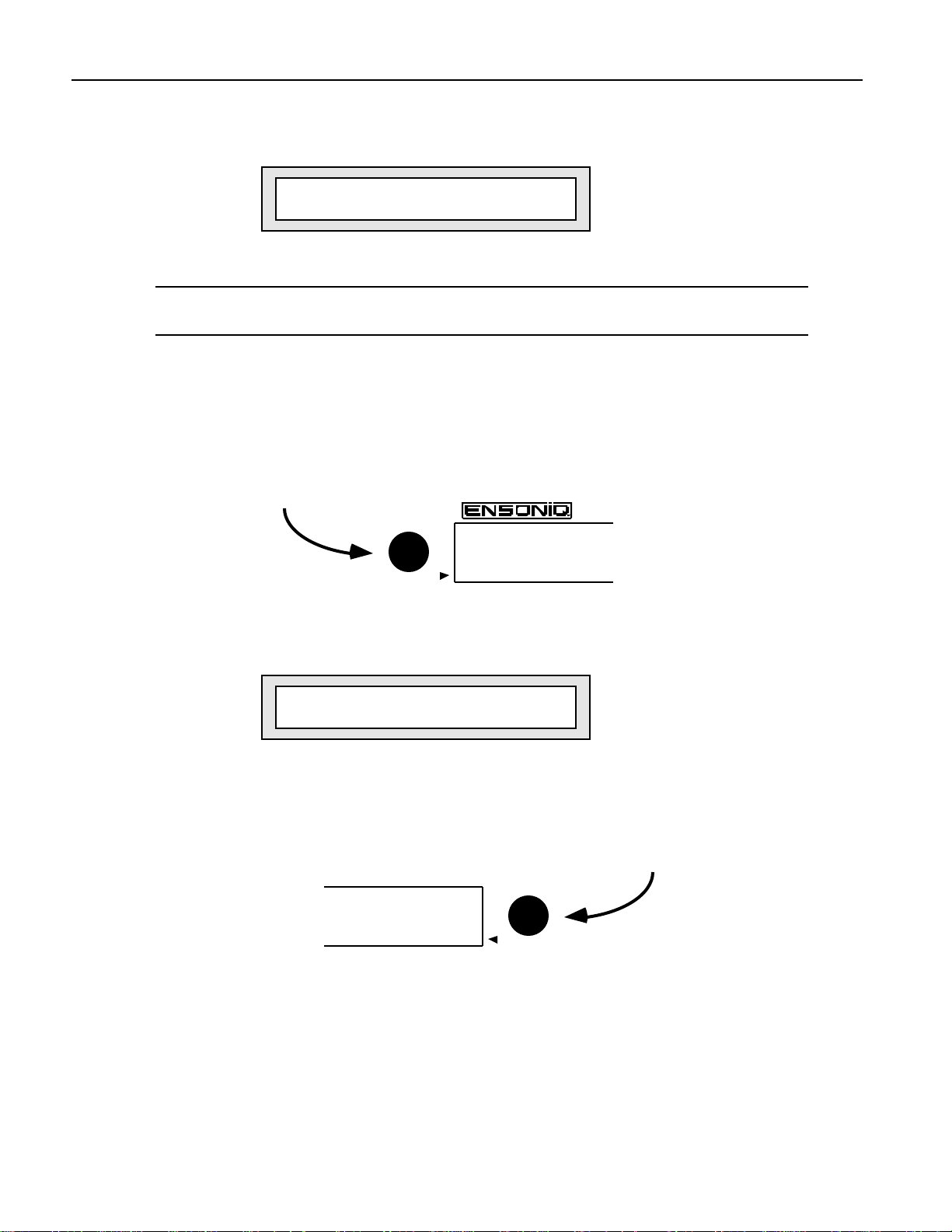
Chapter 1—Welcome
Once the MR-Rack completes its power-up sequence, the display will look something
like this:
You’re ready to start exploring the MR-Rack Sounds.
Note: If you’ve already customized the MR-Rack’s wake-up mode—as described in
Chapter 3—press the Performance and Sound buttons simultaneously.
C hoosing Sounds
The MR-Rack’s SoundFinder™ makes choosing Sounds a snap!
1. Press the Sound button—its LED lights up.
2. Turn the left-hand Sound Type knob on the MR-Rack’s front panel clockwise or
counter-clockwise.
pt01:§01 ROM:004:030
DEMO-SND: Dense Mist
Sound Type
SoundFinder™
As you turn the Sound Type knob, you’ll see different Sound categories appear in the
lower left part of the MR-Rack’s display.
pt01:§01 RAM:005:021
VOCALS : Aaaahhhs
i
Sound Type
3. Find a Sound Type category that interests you.
4. Turn the Sound Name knob clockwise or counter-clockwise to choose a Sound of the
selected type.
64 Voice Expandable Synth
SoundFinder™
Sound Name
2 ENSONIQ MR-Rack Musician's Manual
Page 20
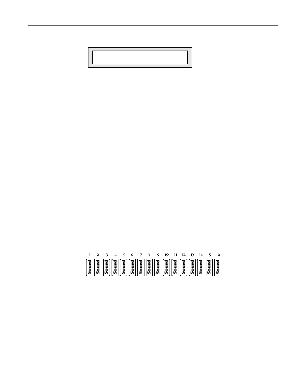
Sound names appear on the lower right-hand portion of the display.
pt01:§01 RAM:001:015
VOCALS :Airy Voices
5. To hear what a Sound sounds like, press the Audition button. A brief demo of the
Sound will play. (You can change what plays when you press the Audition button—see
“Auditioning Sounds on the MR-Rack” in Chapter 3.)
If you’ve already connected your MR-Rack to your MIDI set-up, you can set your
controller to MIDI channel 1 and use it to play the Sound. You can also use MIDI
program changes to select other Sounds. Chapter 2 shows how the MR-Rack can be
wired into your rig.
U nde r st anding the M R - R ac k
The MR-Rack is easy to use, once you understand its simple internal structure. Here’s how
it works.
Chapter 1—Welcome
i
Sound Name
Sounds
Sounds are the basic building blocks of the MR-Rack. They’re constructed from digital
sound waves resident in the MR-Rack’s permanent memory.
If you’ve got a Macintosh or IBM-compatible computer, you can also create your own
Sounds using the Unisyn editor ENSONIQ will supply to you when you send in your
completed MR-Rack warranty card.
You can add additional Sounds by purchasing MRC Series Sound Cards and ENSONIQ EXP
Series Wave Expansion Boards, which will be explained later in this chapter.
Parts
The MR-Rack can play 16 individual Sounds at once. Each Sound fits into one of 16 slots,
called Parts. You can select any MR-Rack Sound for use by any Part.
Each Part can have its own MIDI channel, and provides options—called Part parameters—for
controlling the behavior of the Part. Part parameters also offer tools that allow each Part to
shape the Sound it uses. See Chapter 4 for details.
ENSONIQ MR-Rack Musician's Manual 3
Page 21
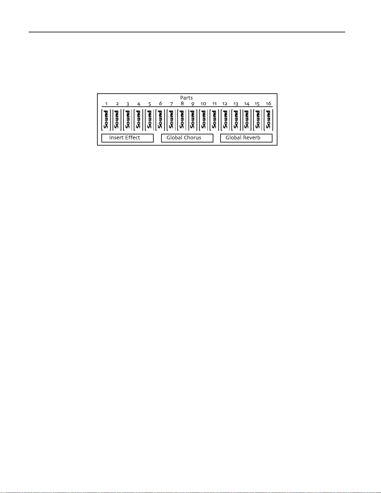
Chapter 1—Welcome
Performances
A collection of up to 16 Parts—including all the Sounds they contain and any of the
alterations you’ve made to them, as well as a complete Effects setup—is called a
Performance.
You can save Performances to the MR-Rack’s internal memory. This is useful for keeping
track of the Sounds and settings for a particular song, project or live performance.
Choosing Performances on the MR-Rack
You can select the Performances in the MR-Rack in a manner very similar to the manner in
which Sounds are selected.
1. Press the Performance button so that its amber LED lights.
2. Turn the Sound Type knob clockwise or counter-clockwise to choose the type of
Performance you’d like.
3. Turn the Sound Name knob clockwise or counter-clockwise to pick an individual
Performance.
Performances can also be selected via MIDI. See “Using MIDI Program Changes” in Chapter
3 for details.
Effects
The MR-Rack contains a powerful 24-bit effect processor that provides a wide range of
Effects that can be applied to any Sound. Each Performance contains three types of Effects:
• an Effect that can be borrowed from one of the Sounds in the Performance, known as
the Insert Effect.
• a Global Chorus
• a Global Reverb
To provide maximum flexibility, the MR-Rack offers six busses to these Effects:
• the Insert FX Bus
• the Chorus FX Bus
• the LightReverb FX Bus
• the MediumReverb FX Bus
• the WetReverb FX Bus
• the Dry FX Bus
Each bus has its own settings that determine how it will use the Effect—or Effects—it can
access, as well as which rear-panel outputs it will ultimately utilize. Parts may be assigned
to any one of the six busses. The bus settings and the Part assignments are saved with each
Performance. For more information on Effects, see Chapter 5.
4 ENSONIQ MR-Rack Musician's Manual
Page 22

Chapter 1—Welcome
Drum Kits
The MR-Rack contains a special category of Sounds called Drum Kit Sounds. Drum Kit
Sounds allow you to have up to 64 non-Drum Kit Sounds assigned to individual keys.
Though these are most commonly drum and percussion Sounds, you can use any kind of
Sound you’d like in a Drum Kit. Each Drum Kit key has its own Volume, Pan, Tuning and
Effect settings. You can use as many Drum Kits in a Performance as there are Parts. In
addition, every Performance offers an editable Drum Kit, called the PerfEditKit, which you
can customize and save as a Drum Kit Sound that you can use again. Drum Kits are
described fully in “Editing Drum Kits” Chapter 4.
Staks
The MR-Rack features an innovative device called a Stak, which is used for grouping Sounds
together on a single MIDI channel. Staks make it easy to create layered Sounds and
keyboard splits. Every Performance provides one Stak, which is created by assigning Parts
to the designated Stak MIDI channel.
Staks provide a number of improvements over the traditional method of stacking or splitting
Sounds assigned to a common MIDI channel. In conventional layers and splits, a program
change sent over the common MIDI channel would set all of the layered or split Sounds to
the same program number, ruining your carefully chosen sound selection—Staks, on the
other hand, are program-change proof. The Stak MIDI channel can also be changed with a
single adjustment, sparing you the work of reassigning every layered or split component
individually, should you need to change the channel you want to use. And since the Stak
MIDI channel is a global setting, you can easily access Staks in ROM Performances without
having to copy the Performance into RAM.
For more information on Staks, see “Using Staks” in Chapter 4.
SoundFinder™
SoundFinder™ is an exclusive ENSONIQ feature that makes it simple to find the Sounds
and Performances you want. Computer users may be familiar with databases, which allow
you to view information in a manner of your choosing. SoundFinder™ operates in much the
same way. The MR-Rack keeps a list of all the Sounds and Performances available to it at
any given time, and shows them to you in logical, musically convenient categories called
Sound Types and Performance Types.
Sound Types let you view Sounds by instrument family—Vocals or Bells, for example—or by
a number of other useful criteria, including the location in the MR-Rack’s memory where
they reside. The ALL-SND category is especially useful, since it shows all of the MR-Rack’s
Sounds arranged in alphabetical order. If you program your own sounds, you can store
them in the USER-SND or *CUSTOM SoundFinder categories.
Performance Types allow you to view Performances according to where in the MR-Rack they
reside.
How the MR-Rack’s Memory Works
Sounds and Performances are stored in memory locations called banks. Each bank may
store up to 128 Sounds—depending on how much memory each Sound requires—and 32
Performances. The MR-Rack is designed to access up to 128 banks. Banks may reside in the
MR-Rack’s internal memory or on PCMCIA data cards and ENSONIQ EXP Series Wave
Expansion Boards you can purchase separately.
Banks become most important when using MIDI Program Changes to select Sounds and
Performance. Each Sound or Performance is invoked with a Bank Select message—which
tells the MR-Rack where the Sound or Performance resides—and a Program Change
ENSONIQ MR-Rack Musician's Manual 5
Page 23

Chapter 1—Welcome
message, which pinpoints the Sound or Performance itself.
Tip: When you’d like to know the necessary Bank Select and Program Change for a
Sound you’ve currently got selected, press the Sounds button and consult the upper
right-hand corner of the MR-Rack’s display: the pair of three-digit numbers tell you,
first, the Bank Select and, second, the Program Change required for that Sound. To
learn a Performance’s Bank Select and Program Change, press the Performance
button—the Performance display shows Bank Select and Program Change
information in the same manner as the Sound display.
ROM and RAM
ROM (“Read Only Memory’”) and RAM (“Random Access Memory”) are the two areas within
the MR-Rack’s internal memory where Performances and Sounds are stored in banks.
Performances and Sounds saved into ROM memory are permanent and unalterable—these
Performances and Sounds are always available. (You can edit them using the MR-Rack’s
Part parameters, and then save the edited versions to non-ROM memory locations.)
Performances and Sounds you edit or create are saved into the MR-Rack’s RAM memory
bank. RAM can be used over and over again, and, therefore, Performances and Sounds
stored in RAM can be edited, re-saved or erased, as you wish.
ROM Cards
The Data Card slot on the MR-Rack’s front panel allows you to add new Sounds and
Performances to the MR-Rack through the purchase of ENSONIQ’s MRC Series Sound
Cards. These PCMCIA ROM cards are inserted into the Data Card slot on the MR-Rack’s
front panel. The Sounds and Performances on these cards are permanent. (You can use the
various Part parameters to customize them, and then save the edited versions to the MRRack’s RAM memory.)
SRAM Cards
The Data Card slot on the MR-Rack’s front panel also allows you to add additional RAM
memory banks through the purchase of SRAM PCMCIA cards, such as ENSONIQ’s MC-512
card. These cards are great for storing your own MR-Rack Sounds and Performances.
EXP Series Wave Expansion Boards
The MR-Rack can be upgraded to hold more digital sound waves and more Sound and
Performance banks with the installation of ENSONIQ EXP Series Wave Expansion Boards.
EXP Boards are mounted inside the MR-Rack’s case—you can easily install them yourself!
For more details, see “Using ENSONIQ EXP Series Wave Expansion Boards” in Chapter 7.
The MR-Rack Display
The MR-Rack’s display has been designed to provide you with all the information you’ll need
as you use the MR-Rack. The display will change as you perform different tasks, since what
you’ll need to know at any given time will vary depending on what you’re doing. Each
chapter in the MR-Rack Musician’s Manual contains an introductory section describing how
the display will function in that chapter’s context.
P laying the M R - R ac k D e m o
The MR-Rack can play special demonstration songs to give you an idea of how terrific it
sounds.
6 ENSONIQ MR-Rack Musician's Manual
Page 24
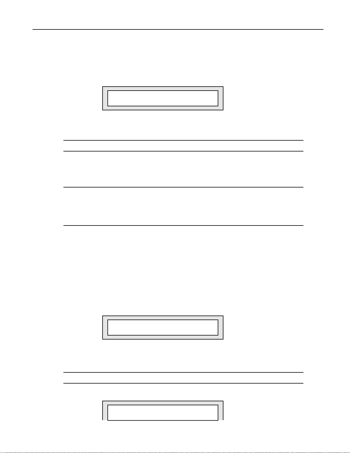
Chapter 1—Welcome
To Play the MR-Rack Main Demo
1. Press the Audition button, and hold it down.
2. While still holding Audition, press the Save button.
3. Let go of both buttons.
In an unexpanded MR-Rack, the display shows:
Hit ENTER to Play:
MAINDEMO:MR Internal
If you’ve installed any Expansion boards or a ROM card containing MAINDEMO-type
demonstration songs, your display will differ. Turn the Value knob counter-clockwise
until the display looks as it does above.
Note: When MR-Rack demos are being viewed or playing, MIDI In is disabled.
4. Press Enter to play the demo.
5. Press Enter again to stop the demo.
6. When you’re done listening to the demo song, press Exit to return to normal MR-Rack
operation.
Note: When you press Exit after selecting and/or listening to the MR-Rack’s demos,
three System parameters are reset if the MR-Rack’s WakeUpMode System parameter
is set to Demo: the AutoSelect FXBus and Part Param Reset parameters are set to
On, and the Perf ProgChgRecv parameter is set to Off (see Chapter 3 if you’d like
more information on these System parameters).
P laying Ot he r De m os
ROM data cards, wave expansion boards and future operating systems can provide
additional demos for your MR-Rack.
To Play Other MR-Rack Demos
1. Press the Audition button, and hold it down.
2. While still holding Audition, press the Save button.
3. Let go of both buttons.
4. Turn the left-hand Sound Type knob to select a demo type.
Hit ENTER to Play:
WORLD : Paddy&Pals
Demo Type
i
The demos you see may differ from the demos shown here.
Note: When MR-Rack demos are being viewed or playing, MIDI In is disabled.
5. Turn the right-hand Sound Name knob to choose a demo.
Hit ENTER to Play:
AMBIENT : MR Trance
ENSONIQ MR-Rack Musician's Manual 7
Page 25
Chapter 1—Welcome
6. Press Enter to play the demo.
7. Press Enter again to stop the demo.
8. When you’re done listening to the demo songs, press Exit to return to normal MR-Rack
operation.
Note: When you press Exit after selecting and/or listening to the MR-Rack’s demos,
three System parameters are reset if the MR-Rack’s WakeUpMode System parameter
is set to Demo: the AutoSelect FXBus and Part Param Reset parameters are set to
On, and the Perf ProgChgRecv parameter is set to Off (see Chapter 3 if you’d like
more information on these System parameters).
Ot he r P oint s of In te r e st
All Notes Off
When using MIDI equipment, there are occasions when your system may get confused. This
can cause a barrage of notes to sound which will continue until you do something to stop
them. The MR-Rack provides an All Notes Off button, which you can double-click (press two
times quickly) to silence these unwanted notes. You'll find it to the right of the MR-Rack’s
display. Think of the All Notes Off button as a “panic button.”
i
Demo Name
All Notes Off
Audition
The MR-Rack’s Battery
The MR-Rack “remembers” Sounds, Performances and its various settings even when its
power is turned off, since it contains a battery which keeps its memory intact. All batteries
eventually become discharged, and though your MR-Rack battery should last for years, you
may eventually need to have it replaced by an Authorized ENSONIQ Repair Station.
Battery Low Warning
The MR-Rack will tell you when its battery needs replacing. It will flash the following when
you power up:
Sorry! Main battery
is low. See manual.
8 ENSONIQ MR-Rack Musician's Manual
Page 26

Chapter 1—Welcome
This display will appear only briefly, and then allow you to proceed normally. Make sure that
everything in RAM that you’d like to keep—or any special System settings—has been safely
stored on a Data Card or external MIDI storage device, and take the MR-Rack to an
Authorized ENSONIQ Repair Station as soon as possible to have the battery replaced.
For more about saving MR-Rack data, see Chapter 6.
If You Experience Odd Behavior
If your MR-Rack is behaving peculiarly—for instance, the display is showing characters that
shouldn’t be there, or you’re experiencing surprising Unexpected Event messages—a soft
reset may cure the problem. There are three special procedures you can try:
• A soft reset is similar to turning the MR-Rack’s power off and then on again. This
procedure doesn’t erase or adversely affect the contents of the MR-Rack’s memory.
• A reinitialization procedure clears out the MR-Rack’s internal memory, including any
system data corruption. Reinitializing erases the contents of the MR-Rack’s internal
memory. This means that any Performances, Sounds, Effect set-ups or PerfEditKits
stored in RAM will be lost. If you decide to reinitialize, try saving any items you want to
preserve to a Data Card or via MIDI SysEx (see Chapter 6 for details).
• A hard reinitialization procedure performs a very deep-level reinitialization of the MRRack. This means that any Performances, Sounds, Effect set-ups or PerfEditKits stored
in RAM will be lost. If you decide to reinitialize, try saving any items you want to
preserve to a Data Card or via MIDI SysEx (see Chapter 6 for details). This procedure
should be used in cases when the MR-Rack’s front-panel buttons, for some reason,
don’t allow you to perform a standard reinitialization.
To Perform A Soft Reset
1. Press and hold down the Save button.
2. While still holding Save, press the Exit button.
If performing a soft reset doesn’t end the strange occurrences, you may need to
reinitialize the MR-Rack. Make sure that everything in RAM that you’d like to keep—or
any special System settings—has been safely stored on a Data Card or external MIDI
storage device before you reinitialize, since reinitialization will clear the MR-Rack’s
internal memory.
To Perform a Standard Reinitialization
Make sure that everything in RAM that you’d like to keep—or any special System
settings—has been safely stored on a Data Card or external MIDI storage device before you
reinitialize, since reinitialization will clear the MR-Rack’s internal memory.
1. Press and hold down the Save button.
2. While still holding Save, press the Enter button.
3. Let go of both buttons.
4. Press the Enter button again to perform the reinitialization
To Perform a Hard Reinitialization
Make sure that everything in RAM that you’d like to keep—or any special System
settings—has been safely stored on a Data Card or external MIDI storage device before you
reinitialize, since reinitialization will clear the MR-Rack’s internal memory.
1. Using its front-panel Power switch, turn the MR-Rack’s power off.
The hard reinitialization process is performed by switching the MR-Rack off and on
eight times in rapid succession. Use the following technique:
2. Turn the MR-Rack’s power back on just until the display flickers on, then shut if off
again, then immediately back on—do this eight times.
If reinitializing the MR-Rack fails to correct the problem, contact an Authorized
ENSONIQ Repair Station.
ENSONIQ MR-Rack Musician's Manual 9
Page 27

Chapter 1—Welcome
A vailable Opt ions f or Your M R - R ac k
These optional accessories are available from your Authorized ENSONIQ Dealer:
• EXP Series Wave Expansion Boards — a user-installable board for Sound memory
expansion. Each EXP Board contains 256 ROM Sounds, up to 24 MB of wave ROM,
with Performances and demos. The MR-Rack can have up to three different EXP Wave
Expansion Boards.
• ROM Card — a PCMCIA type ROM card containing 256 ROM Sounds, and 32 ROM
Performances
• SRAM Card, including ENSONIQ’s MC-512 Card — a PCMCIA type SRAM card
containing a variable number of banks of Sounds and Performances. The number of
banks on a card depends on the size of the card. Each bank is equal in size to the base
unit RAM, and can hold the same number of Sounds (up to 128 RAM Sounds per bank)
and Performances (128 RAM Performances per bank). The number of RAM Sounds
depends on the number of layers in each Sound.
N e e d M or e He lp?
Whether you’re an aspiring programmer looking for additional information about basic effect
processing techniques and MIDI theory, or a professional sound engineer working with
advanced applications, you may want more detailed information beyond the scope of this
manual. The following books can help enhance your understanding of effect processing,
MIDI, and related topics. These, in addition to the numerous monthly magazines, provide a
wealth of information. While we don’t endorse any one of these publications, we offer this
partial list as a resource for you to draw on.
The Mix Bookshelf
For prices and more information call: (800) 233-9604
MIDI
BECOMING A COMPUTER MUSICIAN, Jeff Bowen
MAKING MUSIC WITH YOUR COMPUTER, David (Rudy) Trubitt, Ed.
MIDI: A COMPREHENSIVE INTRODUCTION, Joseph Rothstein
MIDI XPLAINED, Steinberg/Jones
THE MIDI MANUAL, David Huber
UNDERSTANDING MIDI, David Wills
WHAT’S MIDI?, Jon Eiche
RECORDING
IMPROVING YOUR SIGNAL PROCESSING SKILLS, (cassette & manual) Bill Gibson
MASTER HANDBOOK OF ACOUSTICS, F. Alton Everest
MODERN RECORDING TECHNIQUES, Huber & Runstein
SOUND REINFORCEMENT HANDBOOK, Davis & Jones
SYNTHESIS
FUNDAMENTAL TECHNOLOGIES OF THE SYNTHESIZER, Errol G. Specter
SYNTHESIZER PERFORMANCE, Jeff Pressing
WHAT’S A SYNTHESIZER?, Jon Eiche
VIDEOS
SHAPING YOUR SOUND, (video series) Tom Lubin
Alfred Publishing Company
For prices and more information call (818) 891-5999
10 ENSONIQ MR-Rack Musician's Manual
Page 28

MIDI
ADVANCED MIDI APPLICATIONS, GPI
BASIC MIDI APPLICATIONS, GPI
WHAT IS MIDI?, GPI
Hal Leonard Publishing
For prices and more information call (414) 774-3630
MIND OVER MIDI, GPI
TUNING IN: MICROTONALITY IN ELECTRONIC MUSIC, Scott R. Wilkinson
Monthly Magazines
The following magazines offer many specific articles and columns that can provide
additional information.
THE TRANSONIQ HACKER
For prices and more information about this independent news magazine for ENSONIQ
Users, call (503) 227-6848
KEYBOARD
For subscription rates and more information call (800) 289-9919
Chapter 1—Welcome
ELECTRONIC MUSICIAN
For subscription rates and more information call (800) 888-5139
HOME & STUDIO RECORDING
For subscription rates and more information call (818) 407-0744
MIX
For subscription rates and more information call (800) 888-5139
EQ
For subscription rates and more information call (212) 213-3444
ENSONIQ MR-Rack Musician's Manual 11
Page 29

Int r oduc t ion
The MR-Rack is an outstanding addition to any MIDI set-up. This chapter describes how to
connect the MR-Rack in some of the most popular MIDI environments.
The key to setting up any MIDI system is to approach the process in an orderly, methodical
manner. As each cable or wire is added, the system grows in complexity. If you have a firm
grasp of what’s connected, and where, you’ll find managing your rig to be much more
pleasant. As you add more gear—or troubleshoot—the extra care you take now will pay off in
the ease with which you’ll be able to adapt your system to future needs.
Chapter 2—Connections
Ch apt e r 2
Con ne ct i ons
To Get Ready
It’s always good policy to turn everything off—and all volume settings down—before you wire
equipment together. This protects you and your gear from unwelcome surprises.
1. Turn the volume off for each piece of equipment you plan to include in your set-up.
2. Turn down any mixer faders or other volume controls for the sound system you’re
using.
3. Turn off the power for everything being included in your set-up.
What Connections Need to be Made?
In any MIDI system, there are three types of connections to be made:
• MIDI connections
• Audio connections
• Power connections
M aking MID I C onne c t ions
The MR-Rack will communicate with the rest of your equipment via MIDI. The nature of
these connections and the number of MIDI cables you’ll need varies, depending on your setup. Each system has its own needs, which we’ll explain in the individual set-ups in this
chapter.
The MIDI set-ups described in “Making MIDI Connections” are:
• Using the MR-Rack with a controller
• Using the MR-Rack with a workstation
• Using the MR-Rack with a computer/stand-alone sequencer
• Editing Sounds with the MR-Rack and a computer
• Sequencing with the MR-Rack, a computer and a controller
• Using the MR-Rack with a computer, a controller and a merger
• Using the MR-Rack with a computer, a controller and a MIDI patchbay
If you’ve got questions about MIDI itself, or any of the terms above, consult the Glossary or
“What Is MIDI?” sections of Chapter 9.
ENSONIQ MR-Rack Musician's Manual 1
Page 30
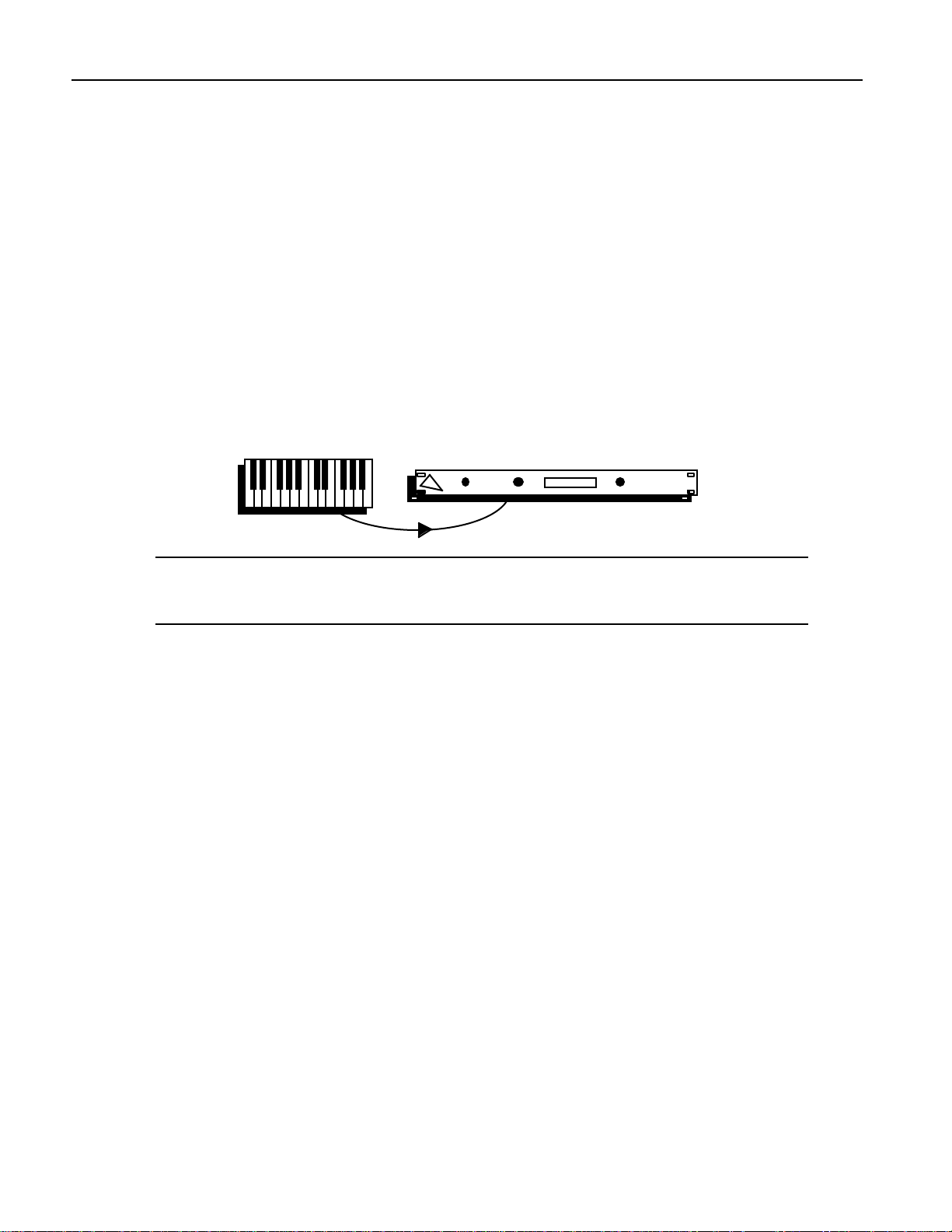
Chapter 2—Connections
Even if your plans for the MR-Rack differ from the scenarios described in this chapter,
you’re likely to find the set-ups you’ll find here useful as starting points for your own system
design.
Using the MR-Rack with a Controller
The MR-Rack can be used as a sound source with any type of MIDI controller. This includes
MIDI keyboards, MIDI drum pads or triggers, MIDI guitars, or anything else a musician
might play which sends out MIDI data.
What You’ll Need
• A single MIDI cable.
• Stereo headphones, for verifying your connections
To Connect the MR-Rack
1. Connect one end of your MIDI cable to your controller’s MIDI Out.
2. Connect the other end to the MR-Rack’s MIDI In.
Note: If your set-up utilizes a MIDI patcher, consult your patcher’s documentation to
learn how to set up the equivalent of this MIDI connection, or see “Using the MRRack With a Computer, Controller and MIDI Patchbay” later in this chapter.
Connecting the Rest of Your System
Now that you’ve made the MIDI connections between your controller and the MR-Rack, skip
ahead to “Making Audio Connections” later in this chapter.
Using the MR-Rack with a Workstation
A workstation is a MIDI instrument with a keyboard, a sequencer, built-in synthesizer or
sampler, effects processor and disk drive or memory card. Adding an MR-Rack vastly
expands the workstation’s sonic palette and provides 64 voices of added polyphony. The MRRack can be played via MIDI from a workstation’s keyboard, or addressed by its sequencer.
Often, a workstation’s disk drive can be used to archive the memory contents of external
devices—such as the MR-Rack—through the “dumping” of MIDI System Exclusive (SysEx)
data. (If you’d like to know more about SysEx, see the Glossary and “What Is MIDI?” in
Chapter 9.) Consult your workstation’s manual to see if yours can receive MIDI SysEx
dumps—if not, you can simply skip the MIDI connection which would run from the MRRack back to your workstation. To learn how to perform a SysEx dump from the MR-Rack,
see Chapter 6.
What You’ll Need
• Two MIDI cables
• Stereo headphones, for verifying your connections
To Connect the MR-Rack
1. Connect one end of a MIDI cable to your workstation’s MIDI Out.
2. Connect the cable’s other end to the MR-Rack’s MIDI In.
3. Connect one end of the other MIDI cable to the MR-Rack’s MIDI Out.
2 ENSONIQ MR-Rack Musician's Manual
Page 31

Chapter 2—Connections
4. Connect its other end to the workstation’s MIDI In.
Note: If you use a MIDI patcher, consult your patcher’s documentation to learn how
to set up the equivalent of these MIDI connections, or see “Using the MR-Rack With a
Computer, Controller and MIDI Patchbay” later in this chapter.
Connecting the Rest of Your System
Now that you’ve made your MIDI connections between your workstation and the MR-Rack,
skip ahead to “Making Audio Connections” later in this chapter.
Using the MR-Rack with a Stand-Alone Sequencer
Sequencers provide a means of playing and/or recording MIDI music (including General
MIDI music). There are essentially two physical types of sequencers. There are sequencer
programs which run on a personal computer, and there are stand-alone boxes dedicated
solely to the job of sequencing. This set-up describes how to use a stand-alone sequencer
with the MR-Rack.
Note: If you’ve got a controller and a MIDI merger, you can follow the instructions in
“Using the MR-Rack with a Computer, Controller and MIDI Merger” later in this
chapter, by simply replacing any references to “computer” with “sequencer.”
A sequencer is also likely to include a disk drive. Often, the drive can be used to archive the
memory contents of external devices—such as the MR-Rack—through the “dumping” of
MIDI System Exclusive (SysEx) data. (If you’d like to know more about SysEx, see the
Glossary and “What Is MIDI?” in Chapter 9.) Consult your sequencer’s manual to see if
yours can receive MIDI SysEx dumps—if not, you can simply skip the MIDI connection
which would run from the MR-Rack back to your sequencer. Chapter 6 describes how to
perform a SysEx dump.
What You’ll Need
• Two MIDI cables
• Stereo headphones, for verifying your connections
ENSONIQ MR-Rack Musician's Manual 3
Page 32

Chapter 2—Connections
To Connect the MR-Rack
1. Connect one end of a MIDI cable to your sequencer’s MIDI Out.
2. Connect the cable’s other end to the MR-Rack’s MIDI In.
3. Connect one end of the other MIDI cable to the MR-Rack’s MIDI Out.
4. Connect its other end to the sequencer’s MIDI In.
Note: If you use a MIDI patcher, consult your patcher’s documentation to learn how
to set up the equivalent of these MIDI connections, or see “Using the MR-Rack With a
Computer, Controller and MIDI Patchbay” later in this chapter.
Connecting the Rest of Your System
Now that you’ve made your MIDI connections between your sequencer and the MR-Rack,
skip ahead to “Making Audio Connections” later in this chapter.
If you’re using a General MIDI (GM) sequencer, you’ll want to see “Using the MR-Rack for
General MIDI Music” near the end of this chapter once you’ve finished setting up.
Editing Sounds with the MR-Rack and a Computer
Computers are powerful musical tools when outfitted with the proper musical hardware and
software. Some computers sport MIDI In/Out/Thru jacks. If yours doesn’t, you’ll need to
purchase a MIDI interface for your computer.
ENSONIQ will provide you with Unisyn sound editing software for your computer when you
fill out and mail in your completed warranty card. Once you’ve installed the Unisyn editor
on your computer, you’ll be able to create your own new Sounds for the MR-Rack (Chapter 9
provides information on using the Unisyn software).
What You’ll Need
• Two MIDI cables
• Stereo headphones, for verifying your connections
To Connect the MR-Rack
1. Connect one end of a MIDI cable to your computer’s MIDI Out.
2. Connect the cable’s other end to the MR-Rack’s MIDI In.
3. Connect one end of the other MIDI cable to the MR-Rack’s MIDI Out.
4 ENSONIQ MR-Rack Musician's Manual
Page 33

Chapter 2—Connections
4. Connect its other end to the computer’s MIDI In.
Note: This set-up is for MR-Rack users working with minimal MIDI hardware. If you
own a MIDI merger or a MIDI patchbay, see “Using the MR-Rack with a Computer,
Controller and MIDI Merger,” or “Using the MR-Rack with a Computer, Controller
and MIDI Patchbay” later in this chapter.
Connecting the Rest of Your System
Now that you’ve made your MIDI connections between your computer and the MR-Rack,
skip ahead to “Making Audio Connections” later in this chapter.
Sequencing with the MR-Rack, a Computer and a Controller
Computers are powerful musical tools when outfitted with the proper musical hardware and
software. Some computers sport MIDI In/Out/Thru jacks. If yours doesn’t, you’ll need to
purchase a MIDI interface for your computer. There are many excellent MIDI sequencing
programs on the market, including General MIDI sequencers. Once you’ve installed one on
your computer, you’ll be able to purchase and play pre-recorded sequences—or record your
own music—using the Sounds onboard the MR-Rack.
This set-up will allow you to play the MR-Rack’s Sounds from your controller while
recording into the computer sequencer. When the sequencer plays back the music, it will
use the same MR-Rack Sounds. When using a computer sequencer, it’s critical that your
controller, sequencer, computer and—if you’re using one—your MIDI interface be configured
correctly. Consult their documentation to learn how to use them with a multi-timbral
module such as the MR-Rack.
What You’ll Need
• Two MIDI cables
• Stereo headphones, for verifying your connections
To Connect the MR-Rack
1. Connect one end of a MIDI cable to your controller’s MIDI Out.
2. Connect the cable’s other end to the computer’s MIDI In.
3. Connect one end of the other MIDI cable to the computer’s MIDI Out.
4. Connect its other end to the MR-Rack’s MIDI In.
ENSONIQ MR-Rack Musician's Manual 5
Page 34

Chapter 2—Connections
Note: This set-up is for MR-Rack users working with minimal MIDI hardware. If you
own a MIDI merger or a MIDI patchbay, see “Using the MR-Rack with a Computer,
Controller and MIDI Merger,” or “Using the MR-Rack with a Computer, Controller
and MIDI Patchbay” later in this chapter.
Connecting the Rest of Your System
Now that you’ve made your MIDI connections between your computer, controller and the
MR-Rack, skip ahead to “Making Audio Connections” later in this chapter.
If you’re using a General MIDI (GM) sequencer, you’ll want to see “Using the MR-Rack for
General MIDI Music” near the end of this chapter once you’ve finished setting up.
Using the MR-Rack with a Computer, Controller and MIDI Merger
Computers are powerful musical tools when outfitted with the proper musical hardware and
software. Some computers provide MIDI In/Out/Thru jacks. If yours doesn’t, you’ll need to
purchase a MIDI interface for your computer. There are many excellent MIDI sequencing
programs on the market, including General MIDI sequencers. Once you’ve installed one on
your computer, you’ll be able to purchase and play pre-recorded sequences—or record your
own music—using the Sounds onboard the MR-Rack. ENSONIQ will provide you with
Unisyn sound editing software for your computer when you fill out and mail in your
completed warranty card. Once you’ve installed the Unisyn editor on your computer, you’ll
be able to create your own new Sounds for the MR-Rack (Chapter 9 explains how to use the
Unisyn software). You can also use the computer’s storage devices to archive the contents of
the MR-Rack’s internal memory, via SysEx dumps. (If you’re unfamiliar with SysEx, see the
Glossary and “What Is MIDI?” in Chapter 9.) Chapter 6 describes how to perform a SysEx
dump.
When using a computer, it’s critical that your controller, all of your computer’s software
and—if you’re using one—your MIDI interface be configured correctly. Consult their
documentation to learn how to use them with a multi-timbral module such as the MR-Rack.
Note: The following set-up will also work for MR-Rack users with a stand-alone
sequencer, a controller and a MIDI merger. Follow the instructions below, and simply
replace any references to “computer” with “sequencer.”
What You’ll Need
• Four MIDI cables
• Stereo headphones, for verifying your connections
To Connect the MR-Rack
1. Connect one end of a MIDI cable to your controller’s MIDI Out.
2. Connect the cable’s other end to one of the merger’s MIDI Ins.
3. Connect one end of a second MIDI cable to the merger’s MIDI Out.
4. Connect its other end to the computer’s MIDI In.
5. Connect a third cable from the computer’s MIDI Out to the MR-Rack’ s MIDI In.
6 ENSONIQ MR-Rack Musician's Manual
Page 35

Chapter 2—Connections
6. Connect the fourth cable from the MR-Rack’s MIDI Out to the merger’s second MIDI In.
MIDI
merger
Note: This set-up is for MR-Rack users with a computer (or a stand-alone sequencer),
a controller and a MIDI merger. If you don’t own a MIDI merger, see “Editing Sounds
with the MR-Rack and a Computer,” Sequencing with the MR-Rack, a Computer and
a Controller,” or “Using the MR-Rack with a Stand-Alone Sequencer” earlier in this
chapter. If you’ve got a MIDI patchbay, see “Using the MR-Rack with a Computer, a
Controller and a MIDI Patchbay” below.
Connecting the Rest of Your System
Now that you’ve made your MIDI connections between your computer, controller and the
MR-Rack, skip ahead to “Making Audio Connections” later in this chapter.
If you’re using a General MIDI (GM) sequencer, you’ll want to see “Using the MR-Rack for
General MIDI Music” near the end of this chapter once you’ve finished setting up.
Using the MR-Rack with a Computer, Controller and MIDI Patchbay
Today’s personal computers can be musical powerhouses when outfitted with MIDI In and
Out jacks and used in conjunction with a device like the MR-Rack. Some computers have
MIDI In/Out/Thru jacks. If yours doesn’t, you’ll need to purchase a MIDI interface for your
computer.
With a computer, you can create new Sounds for the MR-Rack by using the Unisyn editing
software ENSONIQ will provide to you when you send in your completed warranty card (see
Chapter 9 to learn more about using the Unisyn software).
Some people use computer sequencers to play back General MIDI songs that they’ve
purchased. If you’re not sure exactly what General MIDI is, consult the Glossary or “What Is
General MIDI?” in Chapter 9. Other people use computers sequencers to create their own
music. For these musicians, it’s desirable to include a MIDI controller in their
computer/MR-Rack system so they can perform their parts and record them into the
sequencer.
Any storage device connected to the computer— a floppy drive or a hard disk, for
example—can provide a place to store the contents of the MR-Rack’s memory. You can also
use the computer’s storage devices to archive the contents of the MR-Rack’s internal
memory, via SysEx dumps.(If you’re unfamiliar with SysEx, see the Glossary and “What Is
MIDI?” in Chapter 9.) Chapter 6 describes how to perform a SysEx dump.
A MIDI patchbay—especially one with merging capabilities—is the ideal way to connect your
controller, computer, MR-Rack and any other MIDI device. Once everything is wired up to
the patchbay, all inter-device connections are just a few mouse clicks, button presses or
knob twists away.
MIDI patchbays typically provide numbered pairs of MIDI In and Out jacks—each of these
pairs is used by a single MIDI device. Consult your patchbay’s documentation to see if the
manufacturer has recommendations as to which location—that is, pair—should be used by
ENSONIQ MR-Rack Musician's Manual 7
Page 36

Chapter 2—Connections
your controller or computer. If not, you can connect any device to any location.
What You’ll Need
• Six MIDI cables
• Stereo headphones, for verifying your MR-Rack connections
To Make Your MIDI Patchbay Connections
1. Select three patchbay locations: one for your computer, one for your controller and one
for the MR-Rack.
2. Connect the computer’s MIDI Out to the MIDI In of the patchbay location you’ve chosen
for the computer.
3. Connect the same location’s MIDI Out to the computer’s MIDI In.
4. Connect the controller’s MIDI Out to the MIDI In of the patchbay location you’ve chosen
for the controller.
5. Connect the same location’s MIDI Out to the controller’s MIDI In.
6. Connect the MR-Rack’s MIDI Out to the MIDI In of the patchbay location you’ve chosen
for the MR-Rack.
7. Connect the same location’s MIDI Out to the MR-Rack’s MIDI In.
MIDI Patchbay
Consult your patchbay’s documentation to learn how to route MIDI signals from one MIDI
device to another (or others). The optimal routings will vary for the different software
programs you’ll be using—consult their manuals for details.
Connecting the Rest of Your System
Once you’ve programmed your patchbay, skip ahead to “Making Audio Connections” below.
If you’re using a General MIDI (GM) sequencer, you’ll want to see “Using the MR-Rack for
General MIDI Music” near the end of this chapter once you’ve finished setting up.
8 ENSONIQ MR-Rack Musician's Manual
Page 37

M aking Audio C onne c t ions
In any set-up, you’ll need to determine what type of audio connection you’d prefer to
establish between the MR-Rack and the rest of your system. There are a number of options.
• You can listen to the MR-Rack with headphones plugged into the front-panel Phones
jack. This is great for privacy—when you’re practicing, no one else can hear what you’re
up to. It’s also a convenient way to troubleshoot your system, and it’s perfect for simply
experiencing the MR-Rack’s crystal-clear sound without added noise from other
equipment in your rig. The MR-Rack’s Volume knob controls your listening volume.
Phones Volume
Using headphones is always available as an option, regardless of other audio
connections you’ve made with the MR-Rack.
Plugging them in does not automatically mute the other audio outputs from the MRRack.
• If you’d prefer to use the MR-Rack in mono through a traditional keyboard or guitar
amplifier, or through a single fader on a mixing console, connect one end of a 1/4”
phone-type audio cable to the Main Out Left jack on the MR-Rack’s back panel, and the
other end to your amplifier or mixer. The “MR-Rack Output Jacks” section in Chapter 9
contains technical information about the MR-Rack’s output jacks.
Chapter 2—Connections
Aux Out
Right Left
Mono
Right Left
Mono
• If you’d like to operate your MR-Rack in stereo through a pair of faders on a mixing
console, a stereo amplifier or two separate mono amps, you’ll need two 1/4” phone-type
cables. Connect one end of each cable to the MR-Rack’s rear-panel Main Out Left and
Right jacks and the other end to your desired destination. The “MR-Rack Output Jacks”
section in Chapter 9 contains technical information about the MR-Rack’s output jacks.
Aux Out
Right Left
Mono
Right Left
Mono
• You can also connect the MR-Rack to your home stereo, though a bit of caution is
required. The MR-Rack is capable of producing a far greater dynamic range than a
home stereo typically encounters when playing compact discs, cassettes and LPs. See
“Setting Volume Levels” later in this chapter to learn how to safely set the MR-Rack’s
Volume when using it with a home stereo. You’ll need two 1/4”-phone-to-RCA-type
ENSONIQ MR-Rack Musician's Manual 9
Page 38

Chapter 2—Connections
Right Left
Mono
cables, or you’ll need to create some by attaching adapters to standard 1/4” phone or
RCA cables. Connect the 1/4” phone plug end of each 1/4”-to-RCA cable to the MRRack’s rear-panel Main Out Left and Right jacks and the RCA end to your stereo’s
auxiliary inputs. The “MR-Rack Output Jacks” section in Chapter 9 contains technical
information about the MR-Rack’s output jacks.
Right Left
Aux Out
Right Left
Mono
Mono
• If you’re connecting the MR-Rack to an audio patch bay, or if you’ve got four available
inputs on your mixing console, you may elect to use all of the MR-Rack’s Outs. The MRRack offers—in addition to its Main Outs—a pair of Aux Outs, useful for extracting
Sounds or groups of Sounds from the MR-Rack’s Main Outs mix. This allows you to
treat the extracted material with its own outboard processing, or to control its volume
more easily by assigning it its own faders on a mixer. To use all four Outs, you’ll need
four 1/4” phone-type cables. connect one end of each to the MR-Racks’ rear-panel Main
and Aux Outs Left and Right, and the other end to a patch bay position or mixer
channel. The “MR-Rack Output Jacks” section in Chapter 9 contains technical
information about the MR-Rack’s output jacks.
Aux Out
Right Left
Mono
Chapter 3 of the MR-Rack Musician’s Manual describes how to route specific Sounds to the
Aux Outs. The MR-Rack also provides a simple switch for easily sending everything you may
have routed to the Aux Outs back into the Main Outs mix. See “Using the MR-Rack’s Four
Outputs” in Chapter 3.
M aking the P ow e r C onne c t ion
The MR-Rack requires grounded AC power, supplied through the power cord that came with
your MR-Rack. The MR-Rack power supply is intelligent and will adjust to your local
voltage.
To Connect the MR-Rack’s AC Power
1. Connect one end of the MR-Rack’s power cable to a grounded AC outlet.
2. Connect the other end of the MR-Rack’s power cord to the jack labeled “Line” on the
MR-Rack’s rear panel.
3. Connect the other pieces of equipment in your system requiring AC power to AC outlets.
Powering Up
You should always turn on the device which will be transmitting MIDI before you turn on
the device which will be receiving it. If you have a series of MIDI devices, start with the first
device in the chain, then power up the second, the third, and so on. This prevents
10 ENSONIQ MR-Rack Musician's Manual
Page 39

unpleasant surprises which can result from unplanned MIDI information being “spit” out of
transmitting devices as they power up. Such MIDI garbage could confuse a receiving device,
and possibly disable it temporarily. If this should happen for some reason, turn the MRRack’s power off, and then back on.
C onf ir m ing You r MID I C on ne ct ion
It’s important when setting up a MIDI system to verify your connections in an orderly
manner, one step at a time. This is the best way to ascertain what’s working and what isn’t.
The following verification procedure details how to confirm that the MR-Rack is receiving
MIDI properly. If your set-up requires communication in the opposite direction—from the
MR-Rack back to another device—you’ll need to consult that device’s documentation to
ascertain its method for verifying MIDI reception.
MIDI patchbay users should test their set-up with either the controller or the computer
sending MIDI to the MR-Rack.
To Verify that the MR-Rack is Receiving MIDI
• Play a few notes on your controller or play a sequence from your computer or standalone sequencer.
• If you’re using the “Editing Sounds with the MR-Rack and a Computer” set-up, and
Unisyn editing software, open up a Sound-editing window and use the Screen Keys or
Mouse Play feature to play a few notes. (Consult your Unisyn manual for information on
configuration instructions and using these features.)
There’s a MIDI light on the MR-Rack’s front panel, located between the Audition and Save
buttons.
Chapter 2—Connections
All Notes Off
Audition
MIDI
Save
As you play, you should see it flicker. This tells you that your MIDI controller is properly
connected to your MR-Rack.
If the MR-Rack’s MIDI light doesn’t flicker as you play your controller:
1. Check your controller’s MIDI transmission settings to make sure that it is set to
transmit MIDI. Consult your controller’s manual if you’re not sure how to do this.
2. Double-check your MIDI cables. Is your controller’s MIDI Out connected to the MRRack’s MIDI In?
ENSONIQ MR-Rack Musician's Manual 11
Page 40

Chapter 2—Connections
To Confirm that the MR-Rack is Responding to MIDI
1. Press the Performance button on the MR-Rack’s front panel.
2. Turn the left-hand Sound Type knob so that the lower left-hand part of the display
looks like this:
Performance System Effects
Sound Params Mute
perf ROM004:000
ALL-PERF:~PlaySounds
i
Performance Type
Bypass
Part
3. If "→PlaySounds" doesn't already appear in the lower right-hand corner of the display,
turn the right-hand Sound Type knob until the display looks like this:
perf ROM004:000
ALL-PERF:~PlaySounds
4. Plug a pair of stereo headphones into the MR-Rack’s front-panel Phones jack.
5. Bring up the MR-Rack’s Volume knob as you play your controller.
You should be hearing notes as you play. If you’re not hearing anything, check your
MIDI cabling, and make sure that your MIDI controller is set to transmit MIDI.
Se t t ing Vol um e Le ve ls
The MR-Rack’s best sound is obtained when its Volume knob is turned all the way up—you
should always set it as high as possible. How high you can go before audible distortion
occurs will vary, depending on how you’re using the MR-Rack. Here are some tips:
• If you’re using the MR-Rack’s Phones jack, the Volume knob controls your listening
level. Set it to a comfortable level.
• If you’re using the MR-Rack with a keyboard or guitar amplifier, start with your amp
input at a low setting. Turn the MR-Rack’s Volume up as far as you can without
experiencing distortion (unless that’s what you want). Then turn up your amp channel
to a comfortable listening level.
• If you’re routing the MR-Rack directly to a mixing console, or indirectly through a
patchbay, turn the MR-Rack’s Volume all the way up and make adjustments to the
input gain of your mixer faders to ensure the sound doesn’t undesirably distort.
• If you’re listening to the MR-Rack through a home stereo, set your stereo’s volume to its
normal level. With the MR-Rack’s Volume knob all the way down, play your controller
with maximum force, or load up the loudest sequence you have and press Play. Slowly
bring up the MR-Rack’s Volume knob as far as you can without hearing distortion. The
i
Performance Name
12 ENSONIQ MR-Rack Musician's Manual
Page 41

MR-Rack is capable of producing a far greater dynamic range than a home stereo
typically encounters when playing compact discs, cassettes and LPs, and you’ll have to
make sure that loud notes from the MR-Rack will not damage your system.
U sing the M R - R ac k f or Ge ne r al M ID I Music
Once you’ve made all of your connections, getting the MR-Rack ready for General MIDI is
simple:
• Press the System button until the display shows:
System parameters:
Hit ENTER for GM!
• Press the Enter button.
16
Enter
Select Part
Exit
1
Chapter 2—Connections
The MR-Rack is now General-MIDI-ready. Start your General MIDI sequencer and the MRRack will do the rest.
M oving On
Since the MR-Rack is capable of playing 16 different Sounds at once—on 16 different MIDI
channels—you’ll want to get familiar with the way MIDI channels, Sounds and Parts work
together. For a brief overview of the MR-Rack, see “Understanding the MR-Rack” in the first
chapter of the MR-Rack Musician’s Manual, Welcome. For more detailed information on this
subject, turn to Chapter 4.
ENSONIQ MR-Rack Musician's Manual 13
Page 42

Chapter 3—Personalizing Your System
Ch apt e r 3
P er son ali z in g Your Sys t em
The MR-Rack offers a range of options that allow you tailor its behavior to suit your way of
working. These global, system-wide settings operate in the background, letting you get on
with the art of making music. They remain in effect at all times and are preserved when the
MR-Rack’s power is switched off.
To access these options, press the System button. When you press the System button, its
yellow LED will light.
Performance System Effects
Sound Params Mute
Part
Each of the System options is called a parameter. When you change the setting of a
parameter, you are editing the parameter’s value.
To select System parameters, turn the Parameter knob. To edit a System parameter’s value,
turn the Value knob.
Parameter Value
When selecting and editing System parameters, the MR-Rack always shows “System
parameters:” on the top line of the display.
U sing the Global Pit c h Be nd Se t t ings
A Pitch Bend Wheel is a spring-loaded wheel typically located to the far left of a MIDI
keyboard. It’s most commonly used to bend the pitch of notes up or down by pushing the
wheel forward (up) or pulling it back (down). Some manufacturers employ a left/right
scheme.
Bypass
Most MR-Rack Sounds are programmed to respond to MIDI Pitch Bend messages in ways
appropriate to the Sound. The MR-Rack also offers a global Pitch Bend set-up, which is
always available. By setting the Part’s Pitch Bend Up and Down Part parameters to “Sys,”
To access the Parameters described on this page (unless otherwise noted):
Press the System button, turn the Parameter knob to locate the parameter,
and then turn the Value knob to change the parameter's setting.
ENSONIQ MR-Rack Musician’s Manual 1
Page 43

Chapter 3—Personalizing Your System
you can instruct a Part—and its Sound—to use the global Pitch Bend settings instead of
those originally programmed into the Sound. (See “Controlling a Part’s Pitch Bend Response”
in Chapter 4 for details.)
The MR-Rack offers three parameters for controlling the global Pitch Bend range:
• Pitch Bend Up
• Pitch Bend Down
• PitchBendMode
Global Pitch Bend Up and Down
Both Pitch Bend Up and Pitch Bend Down have their own individual settings, and either can
be set to raise or lower the pitch of any Part Sound whose Pitch Bend Up or Down Part
parameter is set to “Sys.”
To Determine the Global Pitch Bend Up Range
1. Press System.
2. Turn the Parameter knob until the display shows “Pitch Bend Up=.”
The global Pitch Bend Up parameter can be set to:
• 1-12dn or 1-12up—the pitch of Part Sounds whose Pitch Bend Up=Sys will be
lowered or raised by the number of equal-temper semitones set here when a Pitch
Bend Wheel is pushed all the way forward
• Off—any Part Sounds whose Pitch Bend Up=Sys will ignore MIDI messages
received from a Pitch Bend Wheel pushed forward
3. Use the Value knob to set the Pitch Bend Up value you desire.
To Determine the Global Pitch Bend Down Range
1. Press System.
2. Turn the Parameter knob until the display shows “Pitch Bend Down=.”
The global Pitch Bend Down parameter can be set to:
• 1-12dn or 1-12up—the pitch of Part Sounds whose Pitch Bend Down=Sys will be
lowered or raised by the number of equal-temper semitones set here when a Pitch
Bend Wheel is pulled all the way back
• Off—any Part Sounds whose Pitch Bend Up=Sys will ignore MIDI messages
received from a Pitch Bend Wheel pulled back
3. Use the Value knob to set the Pitch Bend Down value you desire.
Setting the Global Pitch Bend Mode
The PitchBendMode parameter unlocks a powerful feature that allows you to decide which
notes will be affected by Pitch Bend messages when Part Sounds use the global Pitch Bend.
(See “Controlling a Part’s Pitch Bend Response” in Chapter 4 for details.) It can be set to one
of three values:
• Normal—Pitch Bend messages will affect all notes currently sounding.
• Held—Pitch Bend messages will affect only those notes sounding from keys which are
being physically held down.
Notes held with the sustain pedal or in their release stage will remain at their original
pitch. This feature can be used to create guitar-style pitch bends or to “paint” with
pitch, leaving different notes sustaining at different pitches.
• Prog—the global Pitch Bend will not alter the Normal/Held settings programmed into
To access the Parameters described on this page (unless otherwise noted):
Press the System button, turn the Parameter knob to locate the parameter,
and then turn the Value knob to change the parameter's setting.
2 ENSONIQ MR-Rack Musician’s Manual
Page 44

any Sounds using the global Pitch Bend set-up.
To Determine the Global Pitch Bend’s Behavior
1. Press System.
2. Turn the Parameter knob until the display shows “PitchBendMode=.”
The global PitchBend Mode parameter can be set to:
• Normal—all notes of Part Sounds utilizing the global Pitch Bend will be affected
when Pitch Bend messages are received
• Held—only notes of Part Sounds utilizing the global Pitch Bend set-up which are
being physically held down will be affected when Pitch Bend messages are received
• Prog—notes set to bend according to the programming of Part Sounds utilizing the
global Pitch Bend will be affected when Pitch Bend messages are received
3. Use the Value knob to set the PitchBend Mode to the desired value.
R e t uning the M R - R ac k
Fine Tuning the MR-Rack
There may be a time when you need to use the MR-Rack with an instrument that just can’t
be tuned, or if you have to deal with musicians who don’t want to retune for one reason or
another. The tuning parameter allows you to adjust the MR-Rack's tuning to match other
instruments. The MR-Rack defaults to A=440, with an equi-tempered pitch table.
Chapter 3—Personalizing Your System
To Fine Tune the MR-Rack
1. Press System.
2. Turn the Parameter knob until the display shows “Fine Tuning=.”
3. Use the Value knob to set the amount that you want to raise or lower the pitch. The
pitch can be lowered or raised from -50 to +49 cents.
Note: Setting the MR-Rack to 0 cents is equivalent to A=440. 100 cents is the
equivalent of a semitone.
Using Pitch Tables
The intervals (or relationships) between notes in a scale can be altered to create special pitch
tables. The MR-Rack’s pitch tables have a tuning resolution of 256 cents per semitone. The
default pitch table is “EqualTemper,” the western 12-tone equi-tempered pitch table.
However, you can select from a large assortment of traditional, modern, ethnic, and exotic
pitch tables in the MR-Rack. The MR-Rack also provides a RAM location for a custom pitch
table, and supports the MIDI pitch table Bulk Tuning Dump and Single Note Tuning Change
standards. If you’ve got the appropriate computer program, you can create your own pitch
tables, and transmit them to the MR-Rack via SysEx (see “Pitch Tables and the MIDI
Standard Tuning Format” in Chapter 9 to learn more).
To access the Parameters described on this page (unless otherwise noted):
Press the System button, turn the Parameter knob to locate the parameter,
and then turn the Value knob to change the parameter's setting.
ENSONIQ MR-Rack Musician’s Manual 3
Page 45

Chapter 3—Personalizing Your System
To Assign a Global Pitch Table
1. Press System.
2. Turn the Parameter knob until the display shows “PitchTbl=.”
3. Use the Value knob to select the pitch table that you want to use. This selects the
system pitch table, and will affect all Parts that have their PitchTbl Part parameter set to
PitchTbl=Sys. (See Chapter 4 for details.)
To Assign a Part to a Special Pitch Table
1. Use the Select Part Buttons to choose the Part whose pitch table you’d like to set.
2. Press the Params button.
3. Turn the Parameter knob until the display shows “PitchTbl=.”
PitchTbl can be set to:
• Prog—to use the PitchTbl value programmed into the Sound.
• Sys—to use the global System PitchTbl.
• use one of the special pitch tables built in to the MR-Rack’s memory.
4. Turn the Value knob to set PitchTbl to Sys.
Note: When you select a new Sound for the Part, PitchTbl will be reset to Prog if the
System Part Param Reset parameter is set to On. The Part Param Reset parameter is
described later in this chapter in “Protecting Part Settings.”
This parameter also responds to an NRPN LSB value of 021. See “Using RPNs and NRPNs to
Edit Part Parameters” at the end of Chapter 4.
For a complete list of pitch tables and their descriptions, see Chapter 9.
Sync hr oniz ing the M R - R ac k t o MID I
MR-Rack Sounds and Insert Effect LFOs and DDLs use Low Frequency Oscillators (LFOs) as
a means of creating vibrato and other rhythmic sonic changes. LFOs can be synchronized to
a reference tempo. The MR-Rack contains an internal clock to provide such a reference. The
clock can also be synchronized to MIDI clocks received from an external source—this is
useful if you want to use another device (such as a computer sequencer or drum machine)
as the master clock source, and want to synchronize the MR-Rack’s LFOs to it.
To Set the Global Tempo Clock as the Timing Reference
1. Press System.
2. Turn the Parameter knob until the display shows “Tempo Clock Src=.”
The Tempo Clock Src parameter can be set to:
• Int—to use the MR-Rack’s own internal clock as the timing source.
• MIDI—to use external MIDI clocks as the timing source.
3. Turn the Value knob to set Tempo Clock Src to Int.
To Sync the MR-Rack’s Clock to an External MIDI Device
1. Press System.
2. Turn the Parameter knob until the display shows “Tempo Clock Src=.”
The Tempo Clock Src parameter can be set to:
• Int—to use the MR-Rack's own internal clock as the timing source.
To access the Parameters described on this page (unless otherwise noted):
Press the System button, turn the Parameter knob to locate the parameter,
and then turn the Value knob to change the parameter's setting.
4 ENSONIQ MR-Rack Musician’s Manual
Page 46

• MIDI—to use external MIDI clocks as the timing source.
3. Turn the Value knob to set Tempo Clock Src to MIDI.
To Set the Global Clock Tempo
If the Global Tempo Clock Source parameter is set to Int, this parameter sets the tempo of
the MR-Rack’s internal clock.
1. Press System.
2. Turn the Parameter knob until the display shows “System Tempo=.”
3. The System Tempo parameter can be set to any tempo from 25 bpm (beats per minute)
to 250 bpm.
4. Turn the Value knob to set System Tempo to the tempo that you want to use.
Note: If the Global Tempo Clock Source is set to MIDI, this display will show
“MIDIbpm” as its value, and cannot be changed.
P r ot e c t ing P ar t Se t t ings
Sounds are programmed with their own optimal Part settings built-in, and when you choose
a Sound, those settings are applied to the currently selected Part. The following Part
parameters may be reset when you select a new Sound on a Part: FX Bus (see Chapter 5 for
details), Pitch Bend Up, Pitch Bend Down, Octave Tuning, Coarse Tuning, Fine Tuning,
PtchTbl, Glide Mode, Glide Time, Delay Time, SyncLFO&Noise, Normal LFO Rates, LFO
Depth, LFO Delay Time, Amp Env Attack, Amp Env Decay, Amp Env Release, Filter Cutoff,
Filt Env Attack, Filt Env Decay, Filt Env Release and Amp&FiltEnv Vel.
Chapter 3—Personalizing Your System
You might prefer to choose new Sounds without losing your current Part settings. You can
use the Part Param Reset System parameter to determine whether or not these Part
parameter settings will be retained when you select a new Sound. This parameter affects
Sound selection from the MR-Rack’s front panel, as well as Sound selection through the
reception of MIDI Program Changes.
The Part Param Reset System parameter also affects the response of Parts to a Reset All
Controllers MIDI message. When the ResetControlRecv System parameter—described later
in this chapter—is set to On, a number of Part parameters are reset to default values when
the MR-Rack receives a Reset All Controllers message. (See “Receiving Reset All Controllers
MIDI Messages” later in this chapter.) Setting the Part Param Reset to Off will protect the
settings of the Part parameters listed above from Reset All Controllers MIDI messages.
To Protect Part Parameter Settings When New Sounds are Selected
1. Press System.
2. Turn the Parameter knob until the display shows “Part Param Reset=.”
The Part Param Reset parameter may be set to:
• On—Part parameters will be reset when new Sounds are selected for a Part or
Reset All Controllers MIDI messages are received
• Off—Part parameters will not be reset when new Sounds are selected for a Part, or
when Reset All Controllers MIDI messages are received
3. Use the Value knob to set Part Param Reset to Off.
To Protect Part Parameters from Reset All Controllers MIDI Messages
To access the Parameters described on this page (unless otherwise noted):
Press the System button, turn the Parameter knob to locate the parameter,
and then turn the Value knob to change the parameter's setting.
ENSONIQ MR-Rack Musician’s Manual 5
Page 47

Chapter 3—Personalizing Your System
1. Press System.
2. Turn the Parameter knob until the display shows “Part Param Reset=.”
The Part Param Reset parameter may be set to:
• On—Part parameters will be reset when new Sounds are selected for a Part or
Reset All Controllers MIDI messages are received
• Off—Part parameters will not be reset when new Sounds are selected for a Part, or
when Reset All Controllers MIDI messages are received
3. Use the Value knob to set Part Param Reset to Off.
To Allow the Selection of New Sounds to Reset Part Parameter Settings
1. Press System.
2. Turn the Parameter knob until the display shows “Part Param Reset=.”
The Part Param Reset parameter may be set to:
• On—Part parameters will be reset when new Sounds are selected for a Part or
Reset All Controllers MIDI messages are received
• Off—Part parameters will not be reset when new Sounds are selected for a Part, or
when Reset All Controllers MIDI messages are received
3. Use the Value knob to set Part Param Reset to On.
To Allow Reset All Controllers Messages to Reset Part Parameter Settings
1. Press System.
2. Turn the Parameter knob until the display shows “Part Param Reset=.”
The Part Param Reset parameter may be set to:
• On—Part parameters will be reset when new Sounds are selected for a Part or
Reset All Controllers MIDI messages are received
• Off—Part parameters will not be reset when new Sounds are selected for a Part, or
when Reset All Controllers MIDI messages are received
3. Use the Value knob to set Part Param Reset to On.
Le t t ing t h e MR - R ac k P ic k Your C hor us or R e ve r b
Each Sound in the MR-Rack has a special Effect bus parameter called the Alt. FX Bus. When
a sound uses an Insert Effect, its Alt. FX Bus setting designates a second-choice Effect for
situations in which the Insert Effect is already in use (in Sounds that use an Insert Effect,
the Alt. FX Bus parameter can be edited using the Unisyn editing software). The Alt. FX Bus
is also used for routing non-Insert Effect Sounds to the Global Chorus or Global
Reverb—when you set a Part’s FX Bus parameter to Chorus or one of the Reverbs, you’re
editing the Alt. FX Bus parameter as well.
The MR-Rack can use the Alt. FX Bus to automatically choose an appropriate Chorus or
Reverb for Sounds that are meant to use an Insert Effect but are not assigned to the Insert
Control Part in a Performance. The Sound’s Part will be assigned to the FX Bus designated
by its Alt. FX Bus setting. The AutoSelect FXBus parameter enables this process. For more
on how the MR-Rack ’s Effects work, see Chapter 5.
To access the Parameters described on this page (unless otherwise noted):
Press the System button, turn the Parameter knob to locate the parameter,
and then turn the Value knob to change the parameter's setting.
6 ENSONIQ MR-Rack Musician’s Manual
Page 48

Chapter 3—Personalizing Your System
To Let the MR-Rack Automatically Pick a Sound’s Chorus or Reverb
1. Press System.
2. Turn the Parameter knob until the display shows “AutoSelect FXBus=.”
The AutoSelect FXBus parameter can be set to:
• On—to let the MR-Rack pick the Chorus or Reverb for newly-selected Sounds on
Parts not designated as the Insert Control Part.
• Off—to leave the Part’s FX Bus assignment unchanged when a new Sound is
selected.
3. Use the Value knob to set AutoSelect FXBus to On.
To Protect Part Effect Bus Settings When a New Sound is Selected
1. Press System.
2. Turn the Parameter knob until the display shows “AutoSelect FXBus=.”
The AutoSelect FXBus parameter can be set to:
• On—to let the MR-Rack pick the Chorus or Reverb for newly-selected Sounds on
Parts not designated as the Insert Control Part
• Off—to leave the Part’s FX Bus assignment unchanged when a new Sound is
selected
3. Use the Value knob to set AutoSelect FXBus to Off.
U sing the M R - R ac k’ s F our Out put s
The MR-Rack rear panel offers four audio outputs. There are two stereo pairs: the Main
Outs and the Aux Outs. The Main Outs are used as the primary feed from the MR-Rack. The
Aux Outs are useful for extracting Sounds or groups of Sounds from the MR-Rack’s Main
Out mix. By routing a Sound to the Aux Outs, you can treat it to its own outboard
processing, or control its volume individually by assigning it to its own fader on a mixer.
Use standard balanced (TRS stereo cables) or unbalanced (TS mono cables) for the Main and
Aux Outs.
Aux Out
Right Left
Mono
As the labels below the Aux Out jacks and Main Out jacks indicate, the MR-Rack employs
automatic switching on each pair of outputs:
• Main Outputs Left and Right are normally stereo outputs. However, if nothing is
plugged into the Right Output, the stereo signal will be summed to mono and sent to
the Left Main Output.
• Similarly, the Aux Outputs Left and Right are normally stereo outputs. However, if
nothing is plugged into the Right Aux Output, the stereo signal will be summed to mono
and sent to the Left Aux Output.
Right Left
Mono
The Main Outs
To access the Parameters described on this page (unless otherwise noted):
Press the System button, turn the Parameter knob to locate the parameter,
and then turn the Value knob to change the parameter's setting.
ENSONIQ MR-Rack Musician’s Manual 7
Page 49

Chapter 3—Personalizing Your System
Routing Sounds to Specific Outputs
All Parts—and the Sounds they use—are routed to an FX (Effect) bus. Each bus goes to an
Effect, which is then assigned to either the Main Outs or the Aux Outs. The Dry bus is a
special case in that it’s assigned to the Main or Aux Out without going through an Effect.
These assignments are part of the current Performance and may be saved with the
Performance; the FX Bus parameter setting can also be saved into a Part’s Sound. (See
Chapter 6 for details on saving Performances and Sounds.)
In routing a Sound to a particular pair of Outs, here’s what happens:
• The Sound is assigned to a Part
• The Part is assigned to an FX bus
• The bus goes to an Effect (except the Dry bus, which goes directly to the Outs you
choose)
• The Effect is assigned to either the Main Outs or the Aux Outs
To Send a Part, Its Sound and Effect to the Desired Outputs
1. Use the Select Part Buttons to make sure the Part you want to assign to the Main Outs
is selected.
2. Press the Params button.
3. Turn the Parameter knob until the display shows “FX Bus=.”
4. Using the Value knob, select an Effect bus to route the Part’s Sound through the Effect
you desire.
5. Press the Effect button.
6. Turn the Parameter knob until the display shows:
Hit ENTER to edit:
Output Assigns
7. Press Enter.
8. Turn the Parameter knob until the display shows the Output Assign parameter for the
FX bus you’ve chosen.
Note: The LightReverb, Medium Reverb and WetReverb busses all use the Global
Reverb Output Assign.
9. Use the Value knob to select either the Main or Aux Outs.
To Send a Part and Its Dry Sound to the Desired Outputs
1. Use the Select Part buttons to make sure the Part you want to assign to the Main Outs
is selected.
2. Press the Params button.
3. Turn the Parameter knob until the display shows “FX Bus=.”
4. Using the Value knob, select Dry.
5. Press the Effect button.
To access the Parameters described on this page (unless otherwise noted):
Press the System button, turn the Parameter knob to locate the parameter,
and then turn the Value knob to change the parameter's setting.
8 ENSONIQ MR-Rack Musician’s Manual
Page 50

Chapter 3—Personalizing Your System
6. Turn the Parameter knob until the display shows:
Hit ENTER to edit:
Output Assigns
7. Press Enter.
8. Turn the Parameter knob until the display shows the Output Assign parameter for the
Dry bus.
Note: The LightReverb, MediumReverb and WetReverb busses all use the Global
Reverb Output Assign.
9. Use the Value knob to select either the Main or Aux Outs.
Determining the Behavior of the Aux Outs
The Aux Outs are used for the extraction of Sounds from the Main Outs mix. The MR-Rack
is designed to provide the maximum flexibility when using the Aux Outs in your rig. The
AuxToMainOuts System parameter offers three different ways to employ the Aux Outs. You
can choose which one will work best for you.
When AuxToMainOuts is set to Auto, the MR-Rack employs intelligent jack switching, which
allows it to sense whether or not you’ve got a cable plugged into the Left Aux Out jack. If you
do, the Main and Aux Outs function as totally discrete stereo feeds. If there’s nothing
connected to the jack, any signal sent to the Aux Outputs will be summed into the Main
Outputs. This is convenient for musicians whose limited instrument inputs necessitate an
economical, flexible use of cables, or who anticipate using the Aux Outs only rarely.
Musicians who would prefer to permanently connect all four MR-Rack Outs will find the
remaining two AuxToMainOuts values useful. When the parameter is set to Never, the Aux
and Main Outs are kept discrete. When it’s set to Always, the Aux Outs are summed into the
Main Outs. This allows musicians to leave all four MR-Rack output cables connected. When
the Aux Outs are needed as a separate stereo feed, the AuxToMainOuts parameter can be
set to Never. When only the Main Outs are required, it can be set to Always.
To Enable Automatic Aux Out Routing Based on Cabling
1. Press System.
2. Turn the Parameter knob until the display shows “AuxToMainOuts=.”
The AuxToMainOuts parameter can be set to:
• Never—the Aux and Main Outs will be discrete, even if the Left Aux Out is not
connected
• Always—the Aux signal will be summed into the Main outputs, even if the Left Aux
Out is connected
• Auto—the MR-Rack will sum any Sounds sent to the Aux Outs into the Main Outs
if there’s no cable plugged into the Left Aux Out jack
3. Use the Value knob to set AuxToMainOuts to Auto.
To Use the Aux Outs with Permanently Connected Outputs
1. Press System.
2. Turn the Parameter knob until the display shows “AuxToMainOuts=.”
To access the Parameters described on this page (unless otherwise noted):
Press the System button, turn the Parameter knob to locate the parameter,
and then turn the Value knob to change the parameter's setting.
ENSONIQ MR-Rack Musician’s Manual 9
Page 51

Chapter 3—Personalizing Your System
The AuxToMainOuts parameter can be set to:
• Never—the Aux and Main Outs will be kept as discrete stereo feeds
• Always—the Aux signal will be summed into the Main Out stereo feed
• Auto—the MR-Rack will sum any Sounds sent to the Aux Outs into the Main Outs
if there’s no cable plugged into the Left Aux Out jack
3. Use the Value knob to set AuxToMainOuts=Never when you need to use the Aux Outs as a
discrete stereo feed, or to Always when using the Main Outs only.
A udit ioning Sounds on the M R - R ac k
Pressing the Audition button on the front panel will play a brief Sound audition demo for the
Sound on the currently selected part. The nature of the audition material is determined with
the setting of the Audition System parameter. When the Audition button is pressed, the MRRack can play octaves in any key, a major chord in any key, or a brief piece of music that’s
appropriate to the currently selected Sound Type.
To Set What’s Heard When the Audition Button is Pressed
1. Press System.
2. Turn the Parameter knob until the display shows “Audition=.”
3. The Audition parameter can be set to:
• Sound Type—a short composition appropriate to the currently selected Sound Type
will play when the Audition button is pressed
• A Octaves to G# Octaves—arpeggiated octaves up the keyboard will play when the
Audition button is pressed
• A maj Chord to G# maj Chord—a major chord in a central pitch range will play
when the Audition button is pressed
• A maj Arpeg to G# maj Arpeg—an arpeggiated major chord will play when the
Audition button is pressed
4. Turn the Value knob to set the Audition type that you prefer.
Waking up
You can determine how the MR-Rack will “wake up” when you turn its power on. It can
power up a number of different ways, depending on the setting of the WakeUpMode
parameter. The MR-Rack can turn on showing the last display—or “page”—you viewed when
you turned the MR-Rack off. It can display the last Sound you selected. It can power up
ready for General MIDI. Or it can wake up with the →PlaySounds Performance and Part 1
selected.
Note: The MR-Rack powers on with the Sounds LED lit, except when WakeUpMode is
set to Last Page—in that case, the LED that was lit when the power was turned off
will be lit when the MR-Rack is turned back on.
To access the Parameters described on this page (unless otherwise noted):
Press the System button, turn the Parameter knob to locate the parameter,
and then turn the Value knob to change the parameter's setting.
10 ENSONIQ MR-Rack Musician’s Manual
Page 52

To Set How the MR-Rack Will Wake Up
1. Press System.
2. Turn the Parameter knob until the display shows “WakeUpMode=.”
The WakeUpMode parameter can be set to:
• Last Page—the last page displayed when the MR-Rack was turned off will be
restored when it’s turned on
• Last Sound—the last Sound selected when the MR-Rack was turned off will be
displayed when it’s turned on
• GM—when the MR-Rack is turned on, it will be ready to operate with a General
MIDI sequencer. See "Using the MR-Rack to Play General MIDI Music" later in this
chapter for further details on how the MR-Rack works with General MIDI
• Demo—when the MR-Rack is turned on, the Demo Performance and Part 1 will be
selected, the AutoSelect FX Bus and PartParamReset parameters will be turned on
and the Perf ProgChg parameter will be switched off (these parameters are
described elsewhere in this chapter)
3. Use the Value knob to set Wake Up Mode to the desired value.
P r ot e c t ing t he MR - R ac k’ s M e m or y
When operating in the heat of creativity, it’s all too easy to inadvertently erase things you’d
rather preserve. The MR-Rack offers a special display prompt as a reality check during
activities that could result in the loss of Sounds or Performances you don’t really want to
lose. When saving, copying or initializing Sounds and Performances—or when initializing
data cards—the MR-Rack can be set to display:
Chapter 3—Personalizing Your System
System Write Protect
On! ENTER overrides.
When you encounter this message, you can press Enter to continue what you were doing, or
press Exit to abort the procedure. The Write Protect System parameter allows you to enable
this feature if you feel you’d benefit from this double-check, or to disable it if you’d find the
prompt unnecessary.
To Enable the Write Protect Prompt
1. Press the System button.
2. Use the Parameter knob to scroll until the display shows “Write Protect.”
• Off—the MR-Rack will execute the Save, Copy or Initialize procedure without
displaying the Write Protect prompt
• Prompt—the MR-Rack will display the Write Protect prompt before it executes Save,
Copy or Initialize procedures
3. Use the Value knob to set Write protect to Prompt.
To Disable the Write Protect Prompt
1. Press the System button.
2. Use the Parameter knob to scroll until the display shows “Write Protect.”
• Off—the MR-Rack will execute the Save, Copy or Initialize procedure without
displaying the Write Protect prompt
To access the Parameters described on this page (unless otherwise noted):
Press the System button, turn the Parameter knob to locate the parameter,
and then turn the Value knob to change the parameter's setting.
ENSONIQ MR-Rack Musician’s Manual 11
Page 53

Chapter 3—Personalizing Your System
• Prompt—the MR-Rack will display the Write Protect prompt before it executes Save,
Copy or Initialize procedures
3. Use the Value knob to set Write protect to Off.
Se t t ing th e St ak MI D I C hanne l
The MR-Rack introduces Staks, a convenient new way to create layers and keyboard splits.
Staks are created by assigning two or more MR-Rack Parts—and the Sounds they use—to
the Stak MIDI channel. (See “Using Staks” in Chapter 4 for a fuller explanation of Staks.)
The Stak MIDI channel plays another important role in the operation of the MR-Rack. It can
be used to receive MIDI Program Changes that will select new Performances. This will occur
when the Perf ProgChgRecv System parameter is enabled (see “Changing Performances Via
MIDI” below).
To Set the Stak MIDI Channel
1. Press System.
2. Turn the Parameter knob until the display shows “Stak MIDI Channel=.”
The Stak MIDI channel parameter may be set to any MIDI channel.
3. Use the Value knob to select the Stak MIDI Channel you prefer.
Note: When this parameter is edited, all currently sounding voices on all Parts will be
muted.
A dj ust ing St ak C ohe r e nc e
Since Staks contain multiple Parts, it may appear at times that they respond in a loosely
synchronized manner. This can be a desirable effect, as it makes a Stak sound bigger. In
other situations, it’s not as musically appropriate. The Stak Coherence parameter allows you
to instruct the MR-Rack to fire off all of the Staks voices precisely at once, for a tighter
sound. The Stak Coherence parameter can be used to tighten up any Parts that share MIDI
channels, even when they aren't assigned to the Stak MIDI channel.
Tip: When Stak Coherence=On, the overall timing of Parts that share MIDI channels
may appear a bit sluggish as the MR-Rack perfectly lines up all of the notes before
sounding any of them. If you're sequencing, you can compensate for this slower,
more synchronized response by shifting tracks slightly ahead of the beat.
To Perfectly Synchronize the Start of All Notes in a Stak
1. Press System.
2. Turn the Parameter knob until the display shows “Stak Coherence=.”
The Stak Coherence parameter may be set to:
• Off—the Stak’s notes will sound normally
• On—all notes in a Stak will sound at exactly the same time
3. Use the Value knob to set Stak Coherence to On.
Note: When this parameter is edited, all currently sounding voices on all Parts will be
muted.
To access the Parameters described on this page (unless otherwise noted):
Press the System button, turn the Parameter knob to locate the parameter,
and then turn the Value knob to change the parameter's setting.
12 ENSONIQ MR-Rack Musician’s Manual
Page 54

To Allow All Notes in a Stak to Start Normally
1. Press System.
2. Turn the Parameter knob until the display shows “Stak Coherence=.”
The Stak Coherence parameter may be set to:
• Off—the Stak’s notes will sound normally
• On—all notes in a Stak will sound at exactly the same time
3. Use the Value knob to set Stak Coherence to Off.
Note: When this parameter is edited, all currently sounding voices on all Parts will be
muted.
U sing MID I P r ogr am C han ges
Changing Performances Via MIDI
The MR-Rack allows you to send MIDI Program Changes on the Stak MIDI channel as a
means of selecting Performances. See “Setting the Stak MIDI Channel” above to learn how to
set the Stak MIDI channel.
When the Perf ProgChgRecv System parameter is set to On, Program Changes received on
the Stak MIDI channel will select new Performances. Any Part whose MIDI channel is set to
Stak or to the same channel as the Stak MIDI channel will ignore Program Changes.
Chapter 3—Personalizing Your System
When ProgChgRecv is set to Off, Program Changes received on the Stak MIDI channel won’t
select Performances. They’ll also be ignored by any Parts whose MIDI channel is set to Stak.
Parts which use the same channel as the Stak MIDI channel, however, will respond to
Program Changes received on this channel normally.
Note: The Perf ProgChgRecv parameter only affects Parts whose MIDI channels are set
to Stak, or to the same channel as the Stak MIDI channel. Whether the Perf
ProgChgRecv parameter is set to On or Off, all other Parts receive MIDI Program
Changes according to the settings of their ProgramChngeRecv and Bank Select Recv
Part parameters (see Chapter 4 for details), and the setting of the Global
Bank&ProgChgRecv System parameter described below.
To Select New Performances With MIDI Program Changes
1. Press System.
2. Turn the Parameter knob until the display shows “Stak MIDI Channel=.”
3. Use the Value knob to select the Stak MIDI Channel you prefer.
4. Turn the Parameter knob until the display shows “Perf ProgChgRecv=.”
The Perf ProgChgRecv parameter can be set to:
• On—Program Changes received on the Stak MIDI channel will select new
Performances
• Off—Program Changes received on the Stak MIDI channel won’t select new
Performances.
5. Turn the Value knob to set Perf ProgChgRecv to On
6. Send Program Changes on the Stak MIDI channel to select Performances.
To access the Parameters described on this page (unless otherwise noted):
Press the System button, turn the Parameter knob to locate the parameter,
and then turn the Value knob to change the parameter's setting.
ENSONIQ MR-Rack Musician’s Manual 13
Page 55

Chapter 3—Personalizing Your System
Note: This parameter is overridden if Bank&ProgChgRecv (described below) is set to
Off.
To Disable the Selection of Performances By Program Changes
1. Press System.
2. Turn the Parameter knob until the display shows “Perf ProgChgRecv=.”
The Perf ProgChgRecv parameter can be set to:
• On—Program Changes received on the Stak MIDI channel will select new
Performances
• Off—Program Changes received on the Stak MIDI channel won’t select new
Performances
3. Turn the Value knob to set Perf ProgChgRecv to Off.
Any Parts set to the same channel as the Stak MIDI channel will respond to Program
Changes received on the channel.
Note: This parameter is overridden if Bank&ProgChgRecv (described below) is set to
Off.
Setting the Global Reception of MIDI Bank Selects and Program Changes
The MR-Rack allows you to enable or disable its response to MIDI Bank Selects and Program
Changes on a system-wide basis. The global Bank&ProgChgRecv System parameter
functions as a master switch that can turn off the MR-Rack’s reception of Bank Selects and
Program Changes regardless of the ProgramChngeRecv and Bank Select Recv Part
parameter settings, or the setting of the Perf ProgChgRecv System parameter described
earlier in this chapter. When Bank&ProgChgRecv=On, the above parameters control how
each Part responds to or ignores Bank Select and Program Change messages, and whether
or not Program changes received on the Stak MIDI channel will select new Performances.
When Bank&ProgChgRecv is set to Off, the MR-Rack will ignore MIDI Bank Select and
Program Changes completely.
To Enable Reception of Bank Selects and Program Changes
1. Press System.
2. Turn the Parameter knob until the display shows “Bank&ProgChgRecv=.”
The Bank&ProgChgRecv parameter can be set to:
• On—MIDI Bank Selects and Program Changes will be responded to according to
the settings of the ProgramChngeRecv and Bank Select Recv Part parameter and
the Perf ProgChgRecv System parameter
• Off—the MR-Rack will ignore MIDI Bank Selects and Program Changes
3. Turn the Value knob to set Bank&ProgChgRecv to On.
To Disable Reception of Bank Selects and Program Changes
1. Press System.
2. Turn the Parameter knob until the display shows “Bank&ProgChgRecv=.”
The Bank&ProgChgRecv parameter can be set to:
• On—MIDI Bank Selects and Program Changes will be responded to according to
the settings of the ProgramChngeRecv and Bank Select Recv Part parameter and
the Perf ProgChgRecv System parameter
To access the Parameters described on this page (unless otherwise noted):
Press the System button, turn the Parameter knob to locate the parameter,
and then turn the Value knob to change the parameter's setting.
14 ENSONIQ MR-Rack Musician’s Manual
Page 56

• Off—the MR-Rack will ignore MIDI Bank Selects and Program Changes
3. Turn the Value knob to set Bank&ProgChgRecv to Off.
R e sponding to M ID I “P anic ” M e ssage s
Occasionally MIDI devices get confused. As a result, some MIDI products are able to send
out “panic” messages to quickly bring MIDI chaos under control. The MR-Rack responds to
the following panic messages:
• Reset All Controllers (MIDI controller #121)
• All Notes Off (MIDI controller #123)
• All Sounds Off (MIDI controller #120)
Setting the MR-Rack’s Response to Reset All Controllers MIDI Messages
The ResetControlRecv System parameter allows you to determine how the MR-Rack will
respond to Reset All Controllers MIDI messages. When it’s set to On, and a Part receives a
Reset All Controllers message on its MIDI channel, it will return all of its real-time
controllers and any parameters that respond to MIDI controllers to their default values,
clearing up any hung values or unexpected settings. When ResetControlRecv is set to Off, no
MR-Rack Parts will respond to Reset All Controllers messages. For more information on the
MR-Rack's response to Reset All Controllers messages, see "Reset All Controllers (MIDI
controller 121) Reception Behavior" in Chapter 9.
Chapter 3—Personalizing Your System
To Set the Response to Reset All Controllers Messages
1. Press System.
2. Turn the Parameter knob until the display shows “ResetControlRecv=.”
The ResetControlRecv parameter can be set to:
• Off—the MR-Rack will ignore Reset All Controllers MIDI messages
• On—any Part receiving a Reset All Controllers message on its MIDI channel will
reset its real-time controllers and any parameters that respond to MIDI controllers
to default values
3. Turn the Value knob to set ResetControlRecv to the desired value.
Setting the MR-Rack’s Response to All Notes Off MIDI Messages
The MR-Rack can respond to All Notes Off and All Sounds Off MIDI control messages. When
a Part receives either of these on its MIDI channel, it silences any of its notes that are
currently sounding. The AllNotesOff Recv System parameter is a combined filter for both of
these messages. When it’s set to On, the MR-Rack will respond to them—when it’s set to Off,
it will ignore them.
To Set the MR-Rack’s Response to All Notes Off Messages
1. Press System.
2. Turn the Parameter knob until the display shows “AllNotesOff Recv=.”
This AllNotesOff Recv parameter is a combined All Notes Off (MIDI control #123) and All
Sounds Off (MIDI control #120) reception filter. It can be set to:
• Off—the MR-Rack will ignore the All Notes Off and All Sounds Off MIDI messages
• On—any Part receiving an All Notes Off and/or All Sounds Off MIDI message on its
MIDI channel will silence all of its currently-sounding notes
3. Turn the Value knob to set AllNotesOff Recv to the desired value.
To access the Parameters described on this page (unless otherwise noted):
Press the System button, turn the Parameter knob to locate the parameter,
and then turn the Value knob to change the parameter's setting.
ENSONIQ MR-Rack Musician’s Manual 15
Page 57

Chapter 3—Personalizing Your System
U sing MID I SysEx
Enabling and Disabling System Exclusive Communication
The MR-Rack can use MIDI System Exclusive (or “SysEx”) messages to communicate with
computer programs—such as the Unisyn sound editor ENSONIQ will provide you with when
you send in your completed warranty card—and as a means of archiving the contents of its
memory to an external storage device such as a floppy disk drive or a computer’s hard drive.
SysEx data is a special kind of MIDI data which doesn’t require a specific MIDI channel. The
SysEx Recv System parameter globally enables or disables the MR-Rack’s MIDI SysEx
communication capabilities, with exception of SysEx data dumps, described in Chapter 6,
which can always be performed. (If you’d like to learn more about MIDI SysEx, see “What Is
MIDI” in Chapter 9.)
To Enable or Disable SysEx Communication
1. Press System.
2. Turn the Parameter knob until the display shows “SysEx Recv=.”
The SysEx Recv parameter can be set to:
• Off—the MR-Rack will not receive or transmit MIDI SysEx data, except for the
always-enabled SysEx data dumps described in Chapter 6
• On—the MR-Rack will receive and transmit MIDI SysEx data
3. Use the Value knob to set SysEx Recv to the desired value.
Using SysEx Device IDs
Every MIDI product has its own SysEx identity—but what if you’ve got several MR-Racks
connected at the same time? Each one of them can be assigned its own SysEx Device ID
number, from 000 to 127. In this way, each MR-Rack can identify the MIDI SysEx data that
it’s meant to receive. Of course, it’s vital that no two MR-Racks share the same SysEx Device
ID number.
Note: The SysEx ID number is not a MIDI channel—SysEx data doesn’t require one.
To Set the MR-Rack’s SysEx Device ID Number
1. Press System.
2. Turn the Parameter knob clockwise to “SysEx Device ID=.”
The SysEx Device ID parameter can be set to any number from 000 to 127.
3. Use the Value knob to select the System Exclusive Device ID number you want to use
for this MR-Rack.
Note: When performing SysEx dumps from the MR-Rack using the Dump commands
described in Chapter 6, make note of your MR-Rack’s current SysEx Device ID
number. This number is embedded in the dumped data. Your MR-Rack will need to
be set to this ID number when you want to re-transmit the data back into the MRRack.
Se t t ing Up N e w R e al- Tim e Cont r olle r s
To access the Parameters described on this page (unless otherwise noted):
Press the System button, turn the Parameter knob to locate the parameter,
and then turn the Value knob to change the parameter's setting.
16 ENSONIQ MR-Rack Musician’s Manual
Page 58

Chapter 3—Personalizing Your System
Each Part in the MR-Rack can respond to the following real-time MIDI controllers and
messages:
• Data Entry Slider
• Pitch Bend Wheel
• Mod Wheel
• Foot Pedal
• Sustain/Sostenuto pedals
• MIDI Volume messages
• MIDI Pan messages
• MIDI Expression messages
In addition, the MR-Rack allows you to define four additional real-time MIDI controllers:
System Controller 1, System Controller 2, System Controller 3 and System Controller 4.
These can be assigned to respond to any legitimate MIDI controller. Any one of the four can
be used to modulate the MR-Rack’s Sounds or Effects. See Chapter 5 to learn how to use
one of these System Controllers as an Effect modulator. See Chapter 9 to learn about using
the System Controllers to modulate elements within MR-Rack sounds.
Note: Each Part has four parameters which determine whether or not its Sound
or—when the Part is designated as the Insert Control Part—its Insert Effect will
respond to each of the four controllers. See “Working With System MIDI Controllers”
in Chapter 4 for details.
To Set Up the Four System Controllers
1. Press System.
2. Turn the Parameter knob until the display shows the name of the System Controller
you’d like to use:
• CTRL1—System Controller 1
• CTRL2—System Controller 2
• CTRL3—System Controller 3
• CTRL4—System Controller 4
3. After selecting one of the four System Controllers, use the Value knob to locate the MIDI
controller number you’d like to assign to the System Controller you’ve selected.
To access the Parameters described on this page (unless otherwise noted):
Press the System button, turn the Parameter knob to locate the parameter,
and then turn the Value knob to change the parameter's setting.
ENSONIQ MR-Rack Musician’s Manual 17
Page 59

Chapter 3—Personalizing Your System
Note: If more than one System Controller is assigned to the same MIDI controller
number, only the lower-numbered System Controller will respond to the MIDI
controller.
When the MR-Rack is shipped from the factory:
• CTRL1 is assigned to Breath Controller (MIDI controller #002).
• CTRL2 is assigned to FXControl1 (MIDI controller #012).
• CTRL3 is assigned to PatchSelct (MIDI controller #070).
• CTRL4 is assigned to Timbre (MIDI controller #071).
Le ar ning How M uc h RA M is Avai lable f or N e w Sounds
Unisyn, a computer-based, external sound editing program, can be used to create and edit
your own Sounds. ENSONIQ will provide you a copy of the Unisyn MR-Rack Editor when
you send in your completed MR-Rack warranty card. See the Unisyn documentation to learn
how to install it on your computer. Chapter 9 describes using the Unisyn editor to create
and edit MR-Rack Sounds.
When you create a new Sound, you’ll need to know if there’s enough memory available in
the MR-Rack to accommodate it. Each MR-Rack Sound can contain up to 16 layers. Each
bank can contain up to 361 layers. The amount of free internal memory (RAM) in the MRRack is expressed as the number of layers still available in its RAM Sound bank.
To Find Out How Much Free Memory (RAM) is Available in the MR-Rack
To get an idea of how much RAM memory is available for creating your sounds, the MRRack displays the amount of free Sound layers.
1. Press System.
2. Turn the Parameter knob until the display shows “Free RAM:.”
This read-only display shows the number of free Sound layers still available in RAM.
Le ar ning the N um be r of Banks on a Dat a C ar d
Data cards—or PCMCIA cards, as they’re known throughout the computer and musical
instrument industries—are credit-card-sized memory cards. A PCMCIA card is an easy way
to instantly access new MR-Rack Sounds, Performances, and demos. MR-Rack-formatted
cards may be inserted into the Data Card slot on the MR-Rack ’s front panel. There are two
types of PCMCIA cards that can be used with the MR-Rack.
ROM cards provide new Sounds, Performances and demos in a read-only format that can’t
be erased. Each ENSONIQ MRC Series ROM Sound card offers two Banks of new Sounds,
Performances and demos.
SRAM cards—for saving your own Sounds and Performances. These cards vary in size, from
512k up to 2 MB. The number of banks on a card depends on the card’s size:
• 512k cards can hold 4 Banks of Sounds and Performances
• 1 MB cards can hold 9 Banks of Sounds and Performances
• 2 MB cards can hold 18 Banks of Sounds and Performances
Each card bank is equal in size to the MR-Rack’s RAM memory—with a maximum
To access the Parameters described on this page (unless otherwise noted):
Press the System button, turn the Parameter knob to locate the parameter,
and then turn the Value knob to change the parameter's setting.
18 ENSONIQ MR-Rack Musician’s Manual
Page 60

Chapter 3—Personalizing Your System
capacity of 361 Sound layers—and can hold the same number of Sounds (up to 128)
and Performances (32).
SRAM Cards can be purchased inexpensively from computer supply stores or from
ENSONIQ, whose MC-512 SRAM Card offers 4 Sound/Performance banks.
For more information, see “Using PCMCIA Data Cards” in Chapter 7.
Note: The MR-Rack will not accept Flash PCMCIA cards, or any special-function
PCMCIA cards, such as modem cards for portable computers, etc.
To Learn How Many Banks are on the Currently Installed Card
1. Insert an MR-Rack formatted PCMCIA data card into the Data Card slot with its label
side up and its connection edge toward the MR-Rack.
To learn how to format a PCMCIA SRAM card, see Chapter 7.
The display will momentarily show:
PCMCIA Card Inserted
Registering...
2. Press System.
3. Turn the Parameter knob until the display shows “CRD Size:”
This read-only display shows the number of banks on the installed card. If no card is
installed, the display will show “ No card!” in place of the bank number.
Ide nt if ying Inst alle d Wave Expansion Boar ds
The MR-Rack can accommodate up to three ENSONIQ EXP Series Wave Expansion Boards.
Wave Expansion Boards provide new wave data for the MR-Rack, as well as new Sounds,
Performances and demos. For a full description of how to install and use ENSONIQ EXP
Series Wave Expansion Boards, see “Using ENSONIQ EXP Wave Expansion Boards” in
Chapter 7.
The MR-Rack provides three displays which can identify any EXP Wave Expansion boards
you have installed.
To Identify an Installed Expansion Board
1. Press the System button.
2. Turn the Parameter knob until the display shows:
System parameters:
WaveEXP1:xxxxxxxxxxx
i
Expansion Board name
When an Expansion Board is installed, this read-only display will show the name of the
Expansion Board located in the first slot.
To access the Parameters described on this page (unless otherwise noted):
Press the System button, turn the Parameter knob to locate the parameter,
and then turn the Value knob to change the parameter's setting.
ENSONIQ MR-Rack Musician’s Manual 19
Page 61

Chapter 3—Personalizing Your System
3. Turning the Parameter knob two more times will reveal two more displays which show
the names of the Expansion Boards in Wave EXP Slots 2 and 3 (if they’re installed).
If there are no Expansion Boards installed, the display will show “WaveEXP1= **EMPTY**.”
Note: If you’ve installed Expansion Boards and the MR-Rack appears not to be
recognizing them, carefully repeat the instructions in “How To Install an Expansion
Board” from Chapter 7. If the MR-Rack still doesn’t recognize the Expansion Board,
call ENSONIQ Customer Service at 610-647-3930.
U sing the M R - R ac k t o Play Ge ne r al MID I M usic
General MIDI is an agreed-upon set of sounds and protocols which aims to ensure that, no
matter what brand or model General MIDI instrument you use in conjunction with your
personal computer to play back a General MIDI recording, the music is guaranteed to sound
good. For a more detailed description of General MIDI, see “What Is General MIDI?” found in
Chapter 9.
To Use the MR-Rack as a General MIDI Sound Module
1. Press System.
2. Press System again. The display shows:
System parameters:
Hit ENTER for GM!
3. If you’d like to continue, press Enter. If not, press Exit.
Pressing Enter selects the ROM GM performance, selects Part 1, and sets Perf
ProgChgRecv=Off.
The MR-Rack is now prepared to operate in conjunction with General MIDI. If your GM
sequencer’s MIDI Out is connected to the MR-Rack’s MIDI In, you’re ready to start the
music!
To Set the MR-Rack to Power Up Ready for General MIDI Music
1. Press System.
2. Turn the Parameter knob until the display shows “WakeUpMode=.”
The WakeUpMode parameter can be set to:
• Last Page—the last page displayed when the MR-Rack was turned off will be
restored when it’s turned on
• Last Sound—the last Sound selected when the MR-Rack was turned off will be
displayed when it’s turned on
• GM—when the MR-Rack is turned on, it will be ready to operate with a General
MIDI sequencer
• Demo— when the MR-Rack is turned on, the Demo Performance and Part 1 will be
selected, and Program Changes received on the Stak MIDI channel will choose new
Performances
3. Use the Value knob to set WakeUpMode to GM.
To Reset the MR-Rack for Use with Non-General MIDI Music
To access the Parameters described on this page (unless otherwise noted):
Press the System button, turn the Parameter knob to locate the parameter,
and then turn the Value knob to change the parameter's setting.
20 ENSONIQ MR-Rack Musician’s Manual
Page 62

Chapter 3—Personalizing Your System
1. Press the Performance button.
2. Use the Sound Type and Sound Name knobs to select a new Performance.
When the MR-Rack prepares itself for General MIDI music, it alters the settings of a
number of System parameters.
3. Check the settings of the Part Param Reset, PitchBendMode, AutoSelect FXBus, Perf
ProgChgRecv, Bank&ProgChgRecv, ResetControlRecv, AllNotesOff Recv and SysEx
System parameters to see if you’d like to reset them.
MR-Rack General MIDI Details for the Curious
General MIDI is designed to be extremely easy to use, and requires no background
knowledge of its workings. However, for MR-Rack users who are interested, here’s what
happens when you “Hit ENTER for GM!”
• The MR-Rack selects a General MIDI Performance whose Parts 1-16 are set to MIDI
channels 1-16, respectively. These Parts are pointed towards the MR-Rack’s banks of
General MIDI Sounds, and their Bank Select reception has been disabled so that they’ll
only be able to select Sounds from these banks when they receive Program Changes.
The GM Standard drum kit is assigned to Part 10.
• The System Perf ProgChgRecv parameter is set to Off to ensure that Program Changes
don’t unintentionally select a new, non-GM Performance.
• The System AutoSelect FX Bus parameter is set to Off to allow General MIDI Effect
change messages to control the MR-Rack’s chorus and reverb.
• The Part Param Reset parameter is set to Off to protect various Part parameters that are
preset for General MIDI.
• PitchBendMode is set to Prog so that the GM Sounds are allowed to interpret Pitch
Bend messages as they’re programmed to, in accordance with General MIDI.
• Bank&ProgChgRecv is set to On so that the MR-Rack can respond to General MIDI
Program Changes.
• ResetControlRecv and AllNotesOff Recv are set to On so that the MR-Rack can respond
to MIDI panic messages.
• SysEx Recv is set to On so that you can return the MR-Rack to its original General MIDI
settings any time you like, via a General MIDI On SysEx message.
To access the Parameters described on this page (unless otherwise noted):
Press the System button, turn the Parameter knob to locate the parameter,
and then turn the Value knob to change the parameter's setting.
ENSONIQ MR-Rack Musician’s Manual 21
Page 63

Chapter 4—Parts
Ch apt e r 4
P art s
The MR-Rack can play 16 individual Sounds at once. Each Sound fits into one of 16 slots,
called Parts. You can assign any MR-Rack Sound to any Part.
All 16 Parts, their settings and the current Effects set-up are components of a Performance.
For a conceptual overview of the MR-Rack, see “Understanding the MR-Rack” in Chapter 1.
To Select a Performance
1. Press the Performance button so that its LED lights up. If it’s flashing, press it again.
2. Use the knob to the left of the MR-Rack’s display to select an area of the MR-Rack’s
memory you’d like to select a Performance from.
3. Use the knob on the right side of the display to select a Performance.
To Select a Part
To select a Part, press one of the Select Part buttons, which are located just to the left of the
Parameter knob.
16
for higher-numbered Parts
Select Part
for lower-numbered Parts
The upper button moves upward through the Parts, and the lower one downward. The Part
Number field on the display will change to reflect your Part selection.
Tip: To move more quickly through the Parts, hold down either Select Part button
when the Sound or Params LED is lit—the MR-Rack will scroll through the Parts for
you. You can also hold a Select Part button down and use the Parameter knob to dial
in the desired Part.
Enter
Exit
1
ENSONIQ MR-Rack Musician’s Manual 1
Page 64

Chapter 4—Parts
number
Choosing a Sound for a Part
Each of the 16 Parts in every Performance can have its own Sound. The MR-Rack’s
SoundFinder makes choosing Sounds easy.
To Change Sounds on a Part
1. Using the Select Part buttons, choose a Part.
2. Press the Sound button. The display will look something like this:
Part
Part MIDI
channel
Part Sound
residency
MIDI Bank
Select number
MIDI Program
Change number
l l l m n
pt01 §01 ROM004:080
DEMO-SND: Evolution
i i
Sound Type Sound Name
The MR-Rack display provides helpful information when selecting Sounds. The top line
tells you where you are, starting with the Part Number field, which shows you which of
the 16 Parts you're editing, and the Part MIDI Channel, which shows you which
channel the Part will respond to.
Note: To hear Sounds as you select them, you’ll need to make sure that your MIDI
controller is transmitting on the MIDI channel that the currently selected Part uses.
Any Part can be set to any MIDI channel or the special Stak channel. See “Setting a
Part’s MIDI Channel” later in this chapter to learn how to assign a Part to a MIDI
channel. “Using Staks” describes Staks and how to use them.
The Part Sound Residency is a three-letter abbreviation to tell you where in the MRRack’s memory the current Sound resides. The next two fields provide the current
Sound’s MIDI address: its MIDI Bank location and its Program number.
Tip: When you’ve selected a Sound that you’d like to invoke with MIDI program
changes, the upper right-hand corner of the Sounds display gives you the Bank
Select LSB and Program Change values required to call up the Sound. If you’d like,
you can select Sounds in the MR-Rack with Program Changes that are
unaccompanied by Bank Select messages—they’ll simply choose Sounds from the
currently selected bank. Unaccompanied Bank Select messages can be sent to the
MR-Rack to “arm” a Part for a bank change that will occur when the next
unaccompanied Program Change is received.
3. Turn the Sound Type knob. As you turn it, you’ll see different Sound categories appear
in the lower left part of the MR-Rack’s display.
Tip: You can press the Sound button to toggle the Sound Type display field between
the selected Sound’s musical instrument category and its location within the MRRack’s memory.
4. Locate a SoundFinder Sound Type category that interests you.
(You can find a list of the SoundFinder Sound Types in Chapter 9.)
When you select new Sounds from the MR-Rack’s front panel, each SoundFinder
category remembers which of its Sounds you selected last, and goes immediately to that
Sound when you pick the category again. This makes it easy to get back to your favorite
Sounds.
2 ENSONIQ MR-Rack Musician’s Manual
Page 65

Chapter 4—Parts
5. Turn the Sound Name knob to choose a Sound of the selected type.
Sound names appear on the lower right-hand portion of the display. When you select a
new Sound, any notes currently playing on the selected Part will be silenced.
6. To listen to the Sound you’ve selected, send MIDI data to the MR-Rack on the MIDI
channel to which the Part is assigned, as shown in the display above. Any Part can be
edited to use any MIDI channel.
Note: If you hear more than one Sound playing as you listen to Sounds, it may be
that another Part is set to the same MIDI channel you’re using for the currently
selected Part. Press the Select Part buttons to go through the other Parts and see if
there’s a conflict. If necessary, change the other Parts to a MIDI channel you’re not
using, or mute the unwanted Part. (See “Setting a Part’s MIDI Channel” or “Muting
and Soloing Parts” later in this chapter).
A Note About Sounds and Effects
Most MR-Rack Sound are programmed with an Effect. Each Performance offers three types
of Effects—an Insert Effect, Global Chorus and Global Reverb—and Parts may be routed to
any of the three, or left dry. Sounds often sound best when they’re on a Part that’s been
designated as the current Performance’s Insert Control Part. Chapter 5 provides a full
explanation of the MR-Rack Effects.
To Designate a Part as the Insert Control Part
1. Press the Effects button.
2. Turn the Parameter knob until the bottom line of the display shows the InsertContrlPart
parameter.
3. Turn the Value knob to select the number of the Part you’d like to use as the current
Performance’s Insert Control Part.
Auditioning Sounds
The MR-Rack offers several convenient ways to audition Sounds. You can hear a brief
demonstration of the Sound playing a piece of music appropriate to its SoundFinder Sound
Type category, playing octaves in any key, or playing a major chord, also in any key. As
shipped from the factory, the MR-Rack will play a piece of music appropriate to the
currently selected Sound Type. To learn how to change what you’ll hear when you audition a
Sound, see the Audition parameter in Chapter 3 .
Note: Pressing the Audition button will have no effect when the Sound is being used
on a Part that’s muted.
To Audition a Sound
• Press the Audition button.
To Stop the Auditioning of a Sound
• Press the Audition button again.
You can also turn the Sound Type knob or press any of the MR-Rack's buttons to stop
auditioning.
Editing Parts
Each Part offers a number of options for determining how it—and any Sound the Part
uses—will behave. These options are called Part parameters. When you edit a Part
parameter’s setting, you are editing its value.
To access Part parameters, press the Params button. When you press the Params button,
ENSONIQ MR-Rack Musician’s Manual 3
Page 66

Chapter 4—Parts
its green LED will light.
Once you've pressed the Params button, turn the Parameter knob to select the desired
parameter. To edit a parameter’s value, turn the Value knob.
The MR-Rack display provides helpful information when working with parameters.
Performance System Effects
Sound Params Mute
Part
Parameter Value
Bypass
Select Part
Part number Part MIDI channel Sound Name
m m m
16
Enter
Exit
1
pt01 §01 Harpsichord
Part MIDI Chan = 1
i i
Selected parameter Value setting
The top line tells you where you are, starting with the Part Number field, which shows you
which of the 16 Parts you're editing. To select another Part, press one of the Select Part
buttons, which are located just to the left of the Parameter knob.
16
for higher-numbered Parts
Select Part
for lower-numbered Parts
The upper button moves upward through the Parts, and the lower one downward. The Part
Number field on the display will change to reflect your Part selection.
Tip: To move more quickly through the Parts, hold down either Select Part button
when the Sound or Params LED is lit—the MR-Rack will scroll through the Parts for
you. You can also hold a Select Part button down and use the Parameter knob to dial
in the desired Part.
The Part MIDI Channel field shows which MIDI channel the Part will be responding to, or if
the Part is set to the Stak MIDI channel, which is described later in this chapter. Whenever
you’re selecting Sounds or editing Parts, you can always look to this spot on the display to
quickly learn a Part’s MIDI channel, or if it belongs to a Stak. The Sound Name field tells
you which Sound is assigned to the Part. The bottom line of the display shows the currently
selected parameter on the left, and its current value on the right.
Enter
Exit
1
4 ENSONIQ MR-Rack Musician’s Manual
Page 67

To access the Parameters described on this page (unless otherwise noted):
press the Params button, turn the Parameter knob to locate the parameter,
and then turn the Value knob to change the parameter's setting.
U nde r st anding Par t P ar am e t e r s
The Two Kinds of Part Parameters
Each Part contains a broad selection of settings called Part parameters. These parameters
fall into two general types of settings:
• Some Part parameters control the behavior of the Part, for example, the MIDI channel
on which the selected Part will receive MIDI data, and whether or not the Part will
respond to MIDI Bank Select and Program Change messages and various other MIDI
controllers
• Some Part parameters determine the behavior of the Part’s Sound while it’s being used
by the Part—a broad collection of Sound-modifying tools lets each Part use its Sound in
a manner of your choosing.
Parts Parameters and Sounds
It’s important, when editing Part parameters, to understand the relationship between Parts
and the Sounds they use. You can think of a Part as a bin—or a slot, as mentioned
above—that contains a Sound. When you adjust Part parameters to change the way a
Sound is heard, the Sound is altered only for as long as it’s being used by the Part you’re
editing. You’re not permanently altering the Sound itself—you’re merely changing the way
the Part uses the Sound.
Chapter 4—Parts
When a Part Has Been Edited
Since the MR-Rack’s 16 Parts collectively comprise a Performance, whenever you edit a
Part’s parameters, you’re altering the currently selected Performance. Changes you make to
any of the 16 Parts are temporary until you save this edited Performance to the MR-Rack’s
memory or a PCMCIA card. This is accomplished through the use of the Save:
ThisPerformance command, described below in “Saving a Performance.”
If you’ve used a Part’s parameters to alter the nature of a Sound it’s using, and would like to
save those changes into the Sound itself, the MR-Rack allows you to do so by using the
Save: ThisPart’sSound command, described below in “Saving a Part’s Sound.” By saving a
Part’s Sound, the changes you’ve made to the Sound will be heard whenever the Sound is
selected for use by any Part.
Working With an Edited Performance That Hasn’t Yet Been Saved
When the Performance button is pressed after a Part parameter has been changed—or when
a parameter setting is changed via MIDI while the Performance is being displayed—the word
“EDITED” appears on the display to signify that the Performance has been altered.
(“EDITED” also appears in the Performance display when an Effect has been edited; see
Chapter 5.)
m
perf **EDITED**
ROM-PERF:~PlaySounds
Before you save a Performance, the MR-Rack temporarily stores your changes in an edit
buffer. You can listen to other Performances without losing these edits, as long as you don’t
ENSONIQ MR-Rack Musician’s Manual 5
Page 68

Chapter 4—Parts
To access the Parameters described on this page (unless otherwise noted):
press the Params button, turn the Parameter knob to locate the parameter,
and then turn the Value knob to change the parameter's setting.
do any further editing. Once you make any further changes, those edits will be placed in the
buffer, wiping out your earlier work. To truly protect your edits, you’ll need to save your
Performance, or the Sound—or Sounds—you’ve been working with.
Warning: If a single Performance is transmitted to the MR-Rack via SysEx, it will be
placed in the Performance edit buffer, replacing any edited Performance you have
there. (See Chapter 6 for more information on MIDI SysEx transmission and
reception.)
To Recall an Edited Performance
• Press the Performance button twice if it’s not already lit, or once if it is.
Saving a Performance
When you save a Performance, you save the current Part parameter settings for all 16
Parts—including which Sounds they use—and the current Effects setup (Chapter 5
describes the MR-Rack’s Effects).
To Save a Performance
1. Press the Performance button and select the Performance that you want to save.
2. Press the Save button.
3. Turn the Parameter knob all the way counter clockwise.
4. Turn the Value knob all the way counterclockwise. The display shows:
The Performance button’s LED will begin blinking on and off and the display will flash
“**EDITED**.” You can now hear your edited Performance.
Hit ENTER to:
Save:ThisPerformance
5. Press the Enter button.
If the System Write Protect parameter is set to Prompt, the display will show:
System Write Protect
On! ENTER Overrides.
This display is offered as a double-check for you to make sure you really want to save
this Performance. If you’d like to avoid this prompt in the future, see “Protecting the
MR-Rack’s Memory” in Chapter 3.
6. If you’d like to cancel the operation, press the Exit button. If you’d like to proceed, press
the Enter button. The display now allows you to name your Performance:
6 ENSONIQ MR-Rack Musician’s Manual
Page 69

Chapter 4—Parts
To access the Parameters described on this page (unless otherwise noted):
press the Params button, turn the Parameter knob to locate the parameter,
and then turn the Value knob to change the parameter's setting.
Left knob function Right knob function
m m
LEFT:pos RIGHT:char
New Name=FinePerform
i
New Performance Name
The Parameter knob (left) is used to select the character position within the name. You
will know which character is selected because the position in the display will be
underlined. Turning the knob clockwise moves the location to the right, and
counterclockwise moves it to the left. The Value knob (right) is used to select the alphanumeric character for that location.
7. Use the Parameter and Value knobs to select a name for your Performance.
8. When you’ve named your Performance, press the Enter button.
9. Use the Parameter knob to select either:
• RAM—to save the Performance to the MR-Rack’s internal RAM memory.
• CRD—to save the Performance to an installed data card (see “Formatting a PCMCIA
Card” below for instructions on how to prepare a data card for storage).
10. Use the Value knob to select a specific location for your Performance.
11. When you’ve selected a location for your Performance, press the Enter button. The MRRack will provide confirmation of your Save operation’s success, and then display the
newly-saved Performance.
Warning: When saving a Performance to a data card, avoid removing the card from its
slot until the saving procedure is complete—doing so may result in corrupted data on
the card and/or in the MR-Rack’s internal memory.
Saving a Part’s Sound
When you save a Part’s Sound, all of the selected Part’s parameter settings affecting the way
its Sound is heard become permanent attributes of the Sound.
To Save a Part’s Sound
1. Press the Sound button, and use the Select Part buttons to find the Sound that you
want to save.
2. Press the Save button.
3. Turn the Parameter knob all the way counterclockwise.
4. Turn the Value knob until the display shows:
Hit ENTER to:
Save:ThisPart’ sSound
5. Press the Enter button.
ENSONIQ MR-Rack Musician’s Manual 7
Page 70

Chapter 4—Parts
To access the Parameters described on this page (unless otherwise noted):
press the Params button, turn the Parameter knob to locate the parameter,
and then turn the Value knob to change the parameter's setting.
6. If you’d like to cancel the operation, press the Exit button. If you’d like to proceed, press
7. Use the Parameter and Value knobs to select a name for your Sound.
8. When you’ve named your Sound, press the Enter button.
9. Use the Value knob to select a SoundFinder type for your Sound. This feature allows
10. When you’ve defined a SoundFinder type, press the Enter button.
11. Use the Parameter knob to select either:
12. Use the Value knob to select a specific location for your Sound.
13. When you’ve selected a location for your Sound, press the Enter button. The display
If the System Write Protect parameter is set to Prompt, the display will show:
System Write Protect
On! ENTER Overrides.
This display is offered as a double-check for you to make sure you really want to save
this Sound. If you’d like to avoid this prompt in the future, see “Protecting the MRRack’s Memory” in Chapter 3.
the Enter button. The display now allows you to name your Sound:
Left knob function Right knob function
m m
LEFT:pos RIGHT:char
New Name=MySoundName
i
New Sound Name
The Parameter knob (left) is used to select the character position within the name. You
will know which character is selected because the position in the display will be
underlined. Turning the knob clockwise moves the location to the right, and
counterclockwise moves it to the left. The Value knob (right) is used to select the alphanumeric character for that location.
you to easily locate similar Sounds. For more information about using SoundFinder, see
Chapter 1. For a complete list of SoundFinder types, see Chapter 9.
• RAM—to save the Sound to the MR-Rack’s internal RAM memory.
• CRD—to save the Sound to an installed data card (see “Formatting a PCMCIA
Card” below for instructions on how to prepare a data card for storage).
momentarily confirms the successful completion of your command, and selects the
newly-saved Sound. All of the Part’s Sound-related parameters are reset to their
nominal values.
Warning: When saving a Sound to a data card, avoid removing the card from its slot
until the saving procedure is complete—doing so may result in corrupted data on the
card and/or in the MR-Rack’s internal memory.
If you’d like to install the newly-saved Sound as a SoundFinder category’s favorite, turn the
Value knob one tick clockwise or counter-clockwise and back to register the new Sound as
the current category’s favorite.
The Structure of MR-Rack Sounds
8 ENSONIQ MR-Rack Musician’s Manual
Page 71

Chapter 4—Parts
To access the Parameters described on this page (unless otherwise noted):
press the Params button, turn the Parameter knob to locate the parameter,
and then turn the Value knob to change the parameter's setting.
The MR-Rack contains two types of Sounds: standard Sounds and Drum Kit Sounds.
Standard MR-Rack Sounds—constructed from high-quality digital sound waves resident in
the MR-Rack’s permanent memory or on wave expansion boards—can employ up to 16
layers, any number of which may be heard simultaneously, or switched on and off by
modulators such as velocity.
Drum Kits allow you to have up to 64 different standard Sounds assigned to individual keys
from the B two octaves below Middle C (B1) to the D three octaves above (D7). Though these
are most commonly drum and percussion Sounds, you can use any kind of Sound you’d like
in a Drum Kit. Each Drum Kit key, or DrumKey, has its own Volume, Pan, Effect and Tuning
settings.
Note: When you assign a Sound to a DrumKey, the DrumKey makes note of the
location of the Sound in the MR-Rack’s memory. When you play the DrumKey, it
looks to that location and uses the Sound it finds there. If you edit the Sound or
replace it, the DrumKey will play the edited version or the Sound you’ve replaced it
with. If you’ve assigned a memory card or Expansion board Sound to the DrumKey,
and removed the card or board, the DrumKey will be unable to locate its Sound and
will produce silence when played.
You can use as many Drum Kit Sounds in a Performance as there are Parts. In addition,
every Performance offers an editable Drum Kit, called the PerfEditKit, which you can
customize and save with the Performance or as a new Drum Kit Sound that can be used
again. Drum Kits have a number of special parameters of their own, which are described
“Using Drum Kits” later in this chapter.
The parameters and procedures described in this chapter apply to both types of Sounds,
except as noted.
How Sound-Related Part Parameters Work
Each MR-Rack Sound is programmed on a computer using Unisyn editing software.
(ENSONIQ will provide you with Unisyn software when you send in your warranty card).
This software allows the programming of the individual layers within each Sound (see
Chapter 9 for details). The Part parameters let you quickly alter this programming in two
ways. The parameters offer:
• overrides, which set all of the layers in the currently selected Sound to the absolute
value you set
• offsets, which raise or lower the programmed values by the amount you set
A Part parameter is an override when its typical use would be to set all of a Sound’s layers to
the same absolute value.
Layer 1's parameter is set to 96
Layer 2's parameter is set to 27
Layer 3's parameter is set to 44
When an override parameter is set to “Prog,” the originally programmed setting for each
layer is retained.
An override
value of 10
changes all of
the Sound's
layers to a
setting of 10
Layer 1's parameter is set to 10
Layer 2's parameter is set to 10
Layer 3's parameter is set to 10
ENSONIQ MR-Rack Musician’s Manual 9
Page 72

Chapter 4—Parts
To access the Parameters described on this page (unless otherwise noted):
press the Params button, turn the Parameter knob to locate the parameter,
and then turn the Value knob to change the parameter's setting.
A Part parameter is an offset when it would typically be used to affect all of a Sound’s layers
at once while retaining their different settings in relation to one other. Offset parameters
offer values that have positive/negative aspects (denoted with a “+” or “-”). When an offset is
set to “0,” the originally programmed value for each layer is in effect.
Layer 1's parameter is set to 96
Layer 2's parameter is set to 27
Layer 3's parameter is set to 44
Note: Part offsets adjust layer parameters only within the parameters’ legitimate
ranges—offsets will not force them beyond those limits. If a Part offset parameter
appears to be having no effect, it’s likely that the layer parameter has already
reached its maximum or minimum setting.
An offset
value of +10
raises all of
the Sound's
layers by
value of +10
Ge t t ing Bac k to S quar e One In a Flash
There may be times when you’d like to abandon your Part editing or Sound selections and
quickly return the MR-Rack to the state it was in when you first powered it up.
The MR-Rack contains a special Performance called “→PlaySounds,” which is selected when
you turn the MR-Rack on (unless you’ve changed the MR’s wake-up settings—see Chapter
3).
In the →PlaySounds Performance:
• Parts 1 through 16 are set to MIDI channels 1 through 16.
• a Sound from the DEMO-SND SoundFinder category is selected for each Part.
• all of the Part parameters are reset to their default settings.
• Part 1 is designated as the Insert Control Part (Chapter 5 contains a description of the
Insert Control Part).
• the Sound LED lights.
• Part 1 is selected.
You can instantly reset the MR-Rack to the →PlaySounds Performance, and these settings.
Layer 1's parameter is set to 106
Layer 2's parameter is set to 37
Layer 3's parameter is set to 54
To Instantly Reset the MR-Rack’s Parts, Sounds, and Effects
• Press the Performance and Sound buttons simultaneously.
Protecting Your Part Edits
When you’ve made changes to a Part’s parameters, those changes are temporary until you
save the current Performance or the Part’s Sound. The MR-Rack lets you choose whether
your edits will be retained when new Sounds are selected for Parts, and when the MR-Rack
receives Reset All Controllers MIDI messages.
To Set What Happens to Edits When New Sounds Are Selected
1. Press the System button.
2. Turn the Parameters knob until the display shows:
10 ENSONIQ MR-Rack Musician’s Manual
Page 73

Chapter 4—Parts
To access the Parameters described on this page (unless otherwise noted):
press the Params button, turn the Parameter knob to locate the parameter,
and then turn the Value knob to change the parameter's setting.
System parameters:
Part Param Reset= On
i
This may say “Off”
3. Set the Part Param Reset parameter’s value to suit your needs:
• If you’d prefer Part parameters to be reset for each new Sound selected for a Part,
set Part Param Reset to On.
• If you’d prefer for the current Part parameter settings to remain intact when a new
Sound is selected for that Part, set to Part Param Reset to Off.
To Set the MR’s Response to Reset All Controllers Messages
1. Press System.
2. Turn the Parameter knob until the display shows “ResetControlRecv=.”
The ResetControlRecv parameter can be set to:
• Off—the MR-Rack will ignore Reset All Controllers MIDI messages
• On—any Part receiving a Reset All Controllers message on its MIDI channel will
reset its real-time controllers and any parameters that respond to MIDI controllers
to default values
3. Turn the Value knob to set ResetControlRecv to Off if you want to protect changes
you’ve made to Part parameters, or to On if you prefer Reset All Controllers messages to
reset the Part parameters described above.
M ut ing and Soloing Par t s
The Mute button serves three functions:
• It can mute a Part.
• It can solo a single Part.
• It can group solo multiple Parts.
About the Mute LED
The Mute LED informs you of the mute/solo status of any Part you select:
• The Mute LED turns off if the selected Part is not muted.
• The Mute LED lights solidly if the selected Part is muted.
• The Mute LED flashes if the selected Part is soloed (single or group solo).
Performance System Effects
Sound Params Mute
Part
Bypass
ENSONIQ MR-Rack Musician’s Manual 11
Page 74

Chapter 4—Parts
To access the Parameters described on this page (unless otherwise noted):
press the Params button, turn the Parameter knob to locate the parameter,
and then turn the Value knob to change the parameter's setting.
Mute
The mute function can be used to silence individual Parts. This can be handy as a
temporary measure when you’re refining your set-up. In addition, Performances remember
which Parts are muted—when you save a Performance, the mute status of each Part is saved
as well—so you can also make your mutes a permanent feature of any given Performance.
It’s worth noting that, even though muting turns off a Part’s Sound, MIDI controllers are still
received by the Part. This allows the silenced Part to continue to control the Insert Effect if
it’s designated as a Performance’s Insert Control Part (see Chapter 5 for more information on
Insert Effects).
The setting of the Part Param Reset System parameter (see "Protecting Your Part Edits"
above) will determine whether or not the Part will automatically un-mute when you select a
new Sound for it. If Part Param Reset=On, the Part will be un-muted when you pick a new
Sound; if it’s set to Off, the Part will remain muted until you un-mute it with the Mute
button.
To Mute a Part
1. Make sure the Part you want to mute is selected. If it’s not, use the Select Part buttons
2. Press the Mute button once—its LED will light.
This parameter also responds to an NRPN LSB value of 36. See “Using RPNs and NRPNs to
Edit Part Parameters” at the end of this chapter.
to select it.
To Un-Mute a Part
1. Make sure the Part you want to un-mute is selected. If it’s not, use the Select Part
buttons to select it.
2. Press the Mute button once—its LED will turn off.
This parameter also responds to an NRPN LSB value of 36. See “Using RPNs and NRPNs to
Edit Part Parameters” at the end of this chapter.
Solo
The Mute button can also be used for soloing Parts. When a Part is soloed, all the other
Parts in a Performance are silenced. Soloing allows you to isolate an individual Part when a
number of them are currently responding to incoming MIDI. If more than one Part is
responding to the same MIDI channel—as when you’re using a Stak—soloing lets you listen
to a single Part all by itself. If you’re using a sequencer, soloing provides a way to quickly
turn off all of the Parts so that you can listen to one Part alone.
The MR-Rack’s solo feature is exceptionally smart—when you solo a Part, the MR-Rack
remembers the mute/solo status of all the other Parts in the Performance. When you unsolo the soloed Part, all the other Parts will be conveniently returned to their prior state.
Parts can be soloed temporarily as you refine your set-up. In addition, Performances
remember which Parts are soloed—when you save a Performance, the solo status of each
Part is saved as well—so you can also make a soloed Part a permanent feature of any given
Performance.
12 ENSONIQ MR-Rack Musician’s Manual
Page 75

Chapter 4—Parts
To access the Parameters described on this page (unless otherwise noted):
press the Params button, turn the Parameter knob to locate the parameter,
and then turn the Value knob to change the parameter's setting.
To Solo a Part
1. Make sure the Part you want to solo is selected. If it’s not, use the Select Part buttons to
select it.
2. Double-click the Mute button—its LED will start to blink on and off.
This parameter also responds to an NRPN LSB value of 36. See “Using RPNs and NRPNs to
Edit Part Parameters” at the end of this chapter.
To Un-Solo a Part
1. Make sure the Part you want to un-solo is selected. If it’s not, use the Select Part
buttons to select it.
2. Press the Mute button once—its LED will turn off.
This parameter also responds to an NRPN LSB value of 36. See “Using RPNs and NRPNs to
Edit Part Parameters” at the end of this chapter.
To Learn Whether Other Parts Were Already Muted
While you’ve got a Part soloed, you can tell whether or not the currently muted Parts had
already been muted.
1. Select the Part whose prior status interests you, using the Select Part buttons.
On the top line of the display, next to the number of the Part you selected, the word
“mute” will appear.
m
pt02mute ROM004:000
AC-PIANO: Piano
(The rest of the display will vary depending on what you were doing before you soloed
your Part.)
• If the “mute” is solidly lit, this Part was not muted before you soloed your Part.
• If “mute” is flashing, this Part was muted before you soloed your other Part.
Group Solo
The Mute button can be used to solo multiple Parts, which is referred to as a group solo.
When the group of Parts is soloed, all the other Parts in a Performance are silenced. Soloing
groups of Parts allows you to isolate them when other Parts responding to MIDI are making
them hard to hear. Group soloing would allow you to listen only to particular components in
a Stak, or selected elements of a Performance when using an external sequencer.
The MR-Rack’s solo feature is exceptionally smart—when you solo Parts, the MR-Rack
remembers the mute/solo status of all the other Parts in the Performance. When you unsolo the soloed Parts, all the other Parts will be conveniently returned to their prior state.
Parts can be group soloed temporarily as you refine your set-up. In addition, Performances
remember which Parts are soloed—when you save a Performance, the solo status of each
Part is saved as well—so you can also make a group of soloed Parts a permanent feature of
any given Performance.
ENSONIQ MR-Rack Musician’s Manual 13
Page 76

Chapter 4—Parts
To access the Parameters described on this page (unless otherwise noted):
press the Params button, turn the Parameter knob to locate the parameter,
and then turn the Value knob to change the parameter's setting.
To Group-Solo Parts
1. Make sure the first Part you want to solo is selected. If it’s not, use the Select Part
2. Double-click the Mute button—its LED will start to blink on and off.
3. Repeat these two steps for all of the Parts you want to solo.
This parameter also responds to an NRPN LSB value of 36. See “Using RPNs and NRPNs to
Edit Part Parameters” at the end of this chapter.
To Un-Solo a Part from a Group Solo
1. Make sure the Part you want to un-solo is selected. If it’s not, use the Select Part
2. Quickly double-click the Mute button—the Part’s LED stops blinking, indicating that
This parameter also responds to an NRPN LSB value of 36. See “Using RPNs and NRPNs to
Edit Part Parameters” at the end of this chapter.
To Learn Whether Other Parts Were Already Muted
While you’ve got multiple Parts soloed, you can tell whether or not the currently muted Parts
had already been muted.
1. Select the Part whose prior status interests you, using the Select Part buttons.
buttons to select it.
buttons to select it.
the Part is now muted along with the other un-soloed Parts.
On the top line of the display, next to the number of the Part you selected, the word
“mute” will appear.
m
pt02mute ROM004:000
PIANO-A :StereoGrand
(The rest of the display will vary depending on what you were doing before you soloed
any Parts.)
• If the “mute” is solidly lit, this Part was not muted before you soloed any Parts.
• If “mute” is flashing, this Part was muted before you soloed any Parts.
Se t t ing a P ar t ’ s M ID I Channe l
Each Part can be set to any of the standard 16 MIDI channels, or to a special channel called
the Stak channel.
To Set a Part’s MIDI Channel
1. Use the Select Part buttons to select the Part whose MIDI channel you’d like to set.
2. Press the Params button.
3. Move the Parameter knob all the way counterclockwise. The display will show “Part
MIDI Chan=.”
You can set any Part to any of the 16 MIDI channels, or to Stak.
4. Use the Value knob to select the Part MIDI Channel.
When edited, all currently sounding voices on the selected Part will be muted.
The display will reflect the changes you make.
14 ENSONIQ MR-Rack Musician’s Manual
Page 77

To access the Parameters described on this page (unless otherwise noted):
press the Params button, turn the Parameter knob to locate the parameter,
and then turn the Value knob to change the parameter's setting.
Tip: When a standard Sound (not a Drum Kit) is assigned to a Part, repeatedly
pressing the Params button will toggle between this parameter and the FX Bus
parameter. If the Part uses a Drum Kit, pressing the Params button will toggle
between the Part MIDI Channel parameter and the DrumKey FX Bus parameter.
U sing St aks
The MR-Rack offers a powerful new device for layering Sounds or creating splits—it’s called
a Stak—and there’s one available in each Performance.
Multi-timbral MIDI modules have traditionally offered the possibility of creating layers and
splits by assigning multiple Sounds to the same MIDI channel. (In the case of splits, the
Sounds are mapped to respond to different pitch ranges.) Creating layers and splits in this
manner can be awkward, however, since any program changes on the common MIDI
channel will undo your carefully-designed Sound combinations, forcing all of the Sounds to
the same program. In addition, if you decide to change the MIDI channel you want to use for
the layer or split, you have to individually reset the MIDI channel of each Sound involved.
While you’re free to use the traditional method with the MR-Rack, Staks offer a more elegant
approach.
Chapter 4—Parts
The current Part’s MIDI channel
m
Pt01§01 Harpsichord
Part MIDI Chan= 01
In the MR-Rack, you can create layers and splits by assigning Parts—and their Sounds—to
the Stak MIDI channel. This accomplishes four things:
• All of the Parts—and their Sounds—will respond to the same MIDI channel.
• By changing a single System parameter you can set the entire group of Parts to respond
to the MIDI channel of your choice.
• You can protect your Sound combinations from unintentional alteration.
• You can still customize each Part independently without affecting the other Parts in the
Stak.
To Create a Stak
1. Press the System button and turn the Parameter knob until the following display
appears:
System parameters:
Stak MIDI Channel=01
i
This number may be different on your display
2. Turn the Value knob to select the MIDI channel you want to use to control the Stak.
3. Press the Params button.
4. Press the up or down Select Part buttons until the number of the first Part you want to
ENSONIQ MR-Rack Musician’s Manual 15
Page 78

Chapter 4—Parts
To access the Parameters described on this page (unless otherwise noted):
press the Params button, turn the Parameter knob to locate the parameter,
and then turn the Value knob to change the parameter's setting.
5. Turn the Parameters knob until the bottom line of the display shows “Part MIDI
6. Turn the Value knob until Part MIDI Channel=Stak.
use in your Stak is displayed in the upper-left-hand corner of the display.
Channel.”
Your top line may look a bit different
m
pt01 §01 Harpsichord
Part MIDI Chan= 01
i
This number may be different on your display
Note that the Part’s MIDI channel on the top line of the display has changed to “stak.”
When you’re selecting Sounds for a Part, or editing Part parameters, you can look to
this area to quickly ascertain if the selected Part is assigned to a Stak.
m
pt01stak Harpsichord
Part MIDI Chan= Stak
The Part you’re working with will now respond to MIDI on the Stak MIDI channel you
chose in Step 2.
7. Press the Sounds button.
8. Use the Sound Type knob and the Sound Name knob to select a Sound for the first Part
in your Stak.
9. Repeat Steps 3 through 8 to add other Parts—and Sounds—to the Stak.
Each Part in the Stak can be edited, using the Part parameters described in this chapter,
without affecting the other Parts in the Stak. You create splits by setting Parts in a Stak to
different key ranges with the Key Range Lo and Hi parameters, described later in this
chapter.
The System parameter Stak Coherence allows you to perfectly synchronize the beginning of
any notes played in a Stak. Details on this parameter can be found in Chapter 3 .
Tip: If you’d like to enjoy the layers or splits in any of the MR-Rack’s ROM
Performances, Steps 1 and 2 above will allow you to access them on any MIDI
channel that’s convenient for you.
16 ENSONIQ MR-Rack Musician’s Manual
Page 79

To access the Parameters described on this page (unless otherwise noted):
press the Params button, turn the Parameter knob to locate the parameter,
and then turn the Value knob to change the parameter's setting.
C ont r olling a P ar t ’ s Lou dne ss
The loudness for each Part can be set manually from the MR-Rack’s front panel or via MIDI
Volume or Expression control messages. The Volume amount determines the maximum
loudness of a Part’s Sound. Expression can raise or lower the Part’s level, but only up to the
maximum set by Volume.
Volume setting
Mix (Expression)
This allows you to set an acceptable loudness ceiling for a Part, and to adjust its level
without worrying that it will ever become too loud. It’s also possible to invert the Part’s
response to Volume and Expression messages, so that greater values lower the Part’s
volume, and vice versa. This can be useful, for instance, when you’d like a Part to fade in as
a result of MIDI Volume or Expression messages, while another Part fades out from the very
same messages.
Chapter 4—Parts
127
0
To Set a Part’s Maximum Volume
The Part Volume parameter allows you to override the loudness level programmed into the
Sound currently installed on the Part you’re editing. A Volume setting of 100 will leave the
Sound’s level set as programmed. Lower values will reduce the Sound’s loudness—down by
96dB at a value of 0—and values above 100 will make it louder than programmed.
1. Use the Select Part buttons to choose the Part whose volume ceiling you’d like to set.
2. Press the Params button.
3. Turn the Parameter knob until the display shows “Part Volume=.”
4. Turn the Value knob from 0 to 127 to adjust the part’s Volume, or transmit MIDI
Controller #7 values to the MR-Rack. See “To Enable or Disable a Part’s Reception of
Pitch Bend Messages” later in this chapter.
The MR-Rack’s display will reflect Volume changes made via MIDI just as if you’d made
them from the front panel.
When this parameter is edited on a Part that uses a Drum Kit, all of the Sounds in the
Drum Kit are affected simultaneously by the changes you make.
To Adjust the Relative Loudness of a Part
1. Use the Select Part buttons to choose the Part whose relative loudness you’d like to
adjust.
2. Press the Params button.
3. Turn the Parameter knob until the display shows “Expression (Mix)=.”
The Part Expression parameter allows you to mix the level of the Sound currently
installed on the Part you’re editing, up to the maximum set by the Part Volume
parameter above. A setting of 000 will reduce the Part’s loudness -96dB below the level
set with the Part Volume parameter.
ENSONIQ MR-Rack Musician’s Manual 17
Page 80

Chapter 4—Parts
To access the Parameters described on this page (unless otherwise noted):
press the Params button, turn the Parameter knob to locate the parameter,
and then turn the Value knob to change the parameter's setting.
4. Turn the Value knob from 000 to 127 to adjust the part’s Expression, or transmit MIDI
To Invert a Part’s Response to Volume and Expression Values
The Vol/MixPolarity parameter reverses the manner in which a Part will respond to Volume
and Expression settings. When set to +Pos, the Part will respond normally: higher Volume
and Expression values will result in greater loudness. When it’s set to -Neg, higher Volume
and Expression values will lower the level of the Part’s Sound.
1. Use the Select Part buttons to choose the Part whose relative loudness you’d like to
2. Press the Params button.
3. Turn the Parameter knob until the display shows “Vol/MixPolarity=.”
4. Turn the Value knob to set the Part’s Volume/Mix polarity as you prefer.
Controller #11 values to the MR-Rack. See “To Enable or Disable a Part’s Reception of
Pitch Bend Messages” later in this chapter.
This parameter also responds to an NRPN LSB value of 034. See “Using RPNs and
NRPNs to Edit Part Parameters” at the end of this chapter.
The MR-Rack’s display will reflect Expression changes made via MIDI just as if you’d
made them from the front panel.
When this parameter is edited on a Part that uses a Drum Kit, all of the Sounds in the
Drum Kit are affected simultaneously by the changes you make.
adjust.
When this parameter is edited on a Part that uses a Drum Kit, all of the Sounds in the
Drum Kit are affected simultaneously by the changes you make.
A dj ust ing a P ar t ’ s St er e o Posit ioning
MR-Rack Sounds are programmed to appear in specific places in the left/right stereo field.
By adjusting a Part’s pan setting, you can offset the stereo placement of any Sound it uses.
A value of Center 00 will leave the Sound panned as it was programmed. Lower values will
shift it to the left, and higher values will move it to the right. A Part Pan value of Left -64
shifts a Sound hard left, while +63 shifts it hard right.
64 Left 63 Right
00
Center
If components within the Sound are panned differently, their relative positions will be
maintained as the Part Pan value shifts the Sound in either direction.
To Set a Part’s Panning
1. Use the Select Part buttons to choose the Part whose stereo panning you’d like to
adjust.
18 ENSONIQ MR-Rack Musician’s Manual
Page 81

To access the Parameters described on this page (unless otherwise noted):
press the Params button, turn the Parameter knob to locate the parameter,
and then turn the Value knob to change the parameter's setting.
2. Press the Params button.
3. Turn the Parameter knob until the display shows “Pan=.”
The Pan Part parameter can be set from -64 (hard left) to +63 (hard right).
4. Turn the Value knob to select a location within the stereo field for the part, or transmit
MIDI Controller #10 values to the MR-Rack.
The MR-Rack’s display will reflect Part Pan changes made via MIDI just as if you’d made
them from the front panel.
When this parameter is edited on a Part that uses a Drum Kit, all of the Sounds in the
Drum Kit are affected simultaneously by the changes you make.
A dding Ef f e c ts t o P ar t Sounds
Every MR-Rack Performance contains three Effects:
• a stereo Insert Effect
• a stereo Global Chorus
• a stereo Global Reverb
You’ll find a detailed description of the MR-Rack Effects in Chapter 5.
Parts may be routed to any of these Effects, or left dry. To send a Part’s Sound to an Effect,
the Part must be assigned to an Effect bus. There are six possible busses, named for the
Effect they access. You can select:
• Insert—to send a Part to the Performance’s Insert Effect.
• Chorus—to send a Part through the Global Chorus.
• LightReverb—to add a minimal amount of Global Reverb to a Part’s Sound.
• MediumReverb—to add a greater amount of Global Reverb to a Part’s Sound.
• WetReverb—to add a large amount of Global Reverb to a Part’s Sound.
• Dry—for Parts that you don’t want to send through any of the Effects.
Chapter 4—Parts
Tip: When a standard Sound (not a Drum Kit) is assigned to a Part, repeatedly
pressing the Params button will toggle between this parameter and the Part MIDI
Channel parameter.
The following parameter is not present when the Part being edited uses a Drum Kit.
To Route a Part to an Effect
1. Use the Select Part buttons to choose the Part you’d like to route to an Effect.
2. Press the Params button.
3. Turn the Parameter knob until the display shows “FX Bus=.”
4. Use the Value knob to select Insert, Chorus, LightReverb, MediumReverb, WetReverb, or
Dry.
Routing a Non-Insert Control Part to an FX Bus via MIDI
Part that are not designated as the Insert Control Part can be assigned to the Chorus bus,
one of the Reverb busses or the Dry bus via MIDI. If such a Part receives MIDI controller 93
with a value of 1 or higher, it will be assigned to the Chorus FX bus. If the Part receives
MIDI controller 93 with a zero value, it will be assigned to one of the Reverb busses or the
Dry bus, according to the following scheme:
• If the Part receives a Controller 91 value of 0, it will be assigned to the Dry bus.
ENSONIQ MR-Rack Musician’s Manual 19
Page 82

Chapter 4—Parts
To access the Parameters described on this page (unless otherwise noted):
press the Params button, turn the Parameter knob to locate the parameter,
and then turn the Value knob to change the parameter's setting.
• If the Part receives a Controller 91 value of 1-40, it will be assigned to the LightReverb
bus.
• If the Part receives a Controller 91 value of 41-80, it will be assigned to the
MediumReverb bus.
• If the Part receives a Controller 91 value of 81-127, it will be assigned to the WetReverb
bus.
Tip: See “Using the Insert Control Part to Pick Insert Effects Via MIDI” in Chapter 5
to learn how to select Insert Effects via MIDI.
C ont r olling a P ar t ’ s P it c h Be nd R e spon se
A Pitch-Bend Wheel is a spring-loaded wheel typically located to the far left of a MIDI
keyboard. It’s most commonly used to bend the pitch of notes up or down by pushing the
wheel forward (up) or pulling it back (down). Some manufacturers employ a left/right
scheme.
The MR-Rack offers two parameters—Pitch Bend Up and Pitch Bend Down—that allow you
to separately set how you want each Part to respond to MIDI Pitch Bend messages received
from a Pitch Bend Wheel pushed in either direction.
These parameters will have no effect if the Pitch Bend Recv parameter is set to Off. See “To
Enable or Disable a Part’s Reception of Pitch Bend Messages” later in this chapter.
The following parameter is not present when the Part being edited uses a Drum Kit.
To Set the Part’s Response To a Pitch Bend Wheel Pushed Forward
1. Use the Select Part buttons to choose the Part whose Pitch Bend you’d like to
customize.
2. Press the Params button.
3. Turn the Parameter knob until the display shows “Pitch Bend Up=.”
Pitch Bend Up can be set to:
• 1-12dn or 1-12up—to lower or raise the pitch of the Part’s Sound by 1 to 12 equaltemper semitones when a Pitch Bend Wheel is pushed all the way forward
• Prog—to respond to upward Pitch Bend movements according to the value
programmed into the Sound
• Sys—to use the global System Pitch Bend Up value (see Chapter 3 for details)
• Off—to ignore MIDI messages received from a Pitch Bend Wheel pushed forward
4. Turn the Value knob to select the Pitch Bend Up value you prefer.
This parameter also responds to an RPN LSB value of 000 and an NRPN LSB value of 022.
See “Using RPNs and NRPNs to Edit Part Parameters” at the end of this chapter.
The following parameter is not present when the Part being edited uses a Drum Kit.
To Set the Part’s Response To a Pitch Bend Wheel Pulled Back
1. Use the Select Part buttons to choose the Part whose Pitch Bend you’d like to
customize.
2. Press the Params button.
3. Turn the Parameter knob until the display shows “Pitch Bend Down=.”
Pitch Bend Down can be set to:
20 ENSONIQ MR-Rack Musician’s Manual
Page 83

To access the Parameters described on this page (unless otherwise noted):
press the Params button, turn the Parameter knob to locate the parameter,
and then turn the Value knob to change the parameter's setting.
• 1-12dn or 1-12up—to lower or raise the pitch of the Part’s Sound by 1 to 12 equaltemper semitones when a Pitch Bend Wheel is pulled all the way back
• Prog—to respond to downward Pitch Bend movements according to the value
programmed into the Sound
• Sys—to use the global System Pitch Bend Down value (see Chapter 3 for details)
• Off—to ignore MIDI messages received from a Pitch Bend Wheel pulled back
4. Turn the Value knob to select the Pitch Bend Down value you prefer.
This parameter also responds to an RPN LSB value of 000 and an NRPN LSB value of 023.
See “Using RPNs and NRPNs to Edit Part Parameters” at the end of this chapter.
Note: When you select a new Sound for the Part, Pitch Bend Up and Pitch Bend Down
will be reset to Prog if the System Part Param Reset parameter is set to On (see
Chapter 3 for details).
R e t uning a P ar t
On a global level, the MR-Rack’s overall tuning can be adjusted with the System Fine Tuning
parameter (see Chapter 3 for details). This parameter retunes all the Parts in the MR-Rack
simultaneously. You can also re-tune individual Parts with the Part Octave Shift, Semitone
Shift and Fine Tuning parameters.
Chapter 4—Parts
The following parameter is not present when the Part being edited uses a Drum Kit.
To Re-Tune a Part by Octaves
1. Use the Select Part buttons to choose the Part whose octave tuning you’d like to alter.
2. Press the Params button.
3. Turn the Parameter knob until the display shows “Octave Shift=.”
4. Use the Value knob to retune the Part’s Sound in octave steps, if desired.
A setting of 0oct will result in the Part using the octave tuning value programmed into
any Sound it uses. You can shift the Part up or down by a maximum of four equaltemper octaves.
This parameter also responds to an NRPN LSB value of 011. See “Using RPNs and NRPNs to
Edit Part Parameters” at the end of this chapter.
The following parameter is not present when the Part being edited uses a Drum Kit.
To Re-Tune a Part by Semitones
1. Use the Select Part buttons to choose the Part whose coarse—or semitone—tuning you’d
like to alter.
2. Press the Params button.
3. Turn the Parameter knob until the display shows “Semitone Shift=.”
4. Use the Value knob to set the semitone tuning for the part.
A setting of 0st will result in the Part using the semitone tuning value programmed into
any Sound it uses. You can shift the Part upward by a maximum of 63 keyboard equaltemper semitones or downward by a maximum of 64.
This parameter also responds to an RPN LSB value of 002. See “Using RPNs and NRPNs to
Edit Part Parameters” at the end of this chapter.
ENSONIQ MR-Rack Musician’s Manual 21
Page 84

Chapter 4—Parts
To access the Parameters described on this page (unless otherwise noted):
press the Params button, turn the Parameter knob to locate the parameter,
and then turn the Value knob to change the parameter's setting.
The following parameter is not present when the Part being edited uses a Drum Kit.
To Fine-Tune a Part
1. Use the Select Part buttons to choose the Part whose fine-tuning you’d like to alter.
2. Press the Params button.
3. Turn the Parameter knob until the display shows “Fine Tuning=.”
4. Use the Value knob to adjust the fine tuning for the Part.
A setting of 0cents will result in the Part using the fine-tuning value programmed into
any Sound it uses. You can lower or raise the Part's fine tuning by -50 to +49 cents.
100 cents equals one semitone.
This parameter also responds to an RPN LSB value of 001. See “Using RPNs and NRPNs to
Edit Part Parameters” at the end of this chapter.
Note: When you select a new Sound for the Part, all of the Part tuning values will be
reset to obey the tuning values programmed into the new Sound if the System Part
Param Reset parameter is set to On (see Chapter 3 for details).
U sing Spe c ial P it c h Table s
The MR-Rack provides a number of special pitch tables, as well as a custom pitch table
which you can design on your computer with the proper software and transmit via MIDI over
to the MR-Rack. "About RAM Pitch Tables" in Chapter 9 provides detailed information on
creating your own pitch tables, and Chapter 3 contains more information on setting the
MR-Rack’s system, or global, pitch table. Any Part can be assigned to use one of these
special tuning tables.
The following parameter is not present when the Part being edited uses a Drum Kit.
To Assign a Part to a Special Pitch Table
1. Use the Select Part buttons to choose the Part whose pitch table you’d like to set.
2. Press the Params button.
3. Turn the Parameter knob until the display shows “PitchTbl=.”
PitchTbl can be set to:
• Prog—to use the PitchTbl value programmed into the Sound
• Sys—to use the global System PitchTbl (see Chapter 3 for details)
• One of the special pitch tables built in to the MR-Rack’s memory
Chapter 9 provides a list of the MR-Rack pitch tables.
4. Turn the Value knob to select the PitchTbl value you prefer.
Note: When you select a new Sound for the Part, PitchTbl will be reset to Prog if the
System Part Param Reset parameter is set to On (see Chapter 3 for details).
This parameter also responds to an NRPN LSB value of 021. See “Using RPNs and NRPNs to
Edit Part Parameters” at the end of this chapter.
D e t e r m ining Whe t he r a P ar t ’ s Sound Will Glide
It can be desirable for the notes in a Sound to glide from one to the next as you play them.
22 ENSONIQ MR-Rack Musician’s Manual
Page 85

Chapter 4—Parts
To access the Parameters described on this page (unless otherwise noted):
press the Params button, turn the Parameter knob to locate the parameter,
and then turn the Value knob to change the parameter's setting.
By setting the Part Glide Mode parameter to On, the Sound the Part is using will be
endowed with this gliding capability. Some of the MR-Rack’s Sounds are already
programmed with components that glide between notes—if you’d like, you can disable the
glide built into such a Sound by setting its Part’s Glide Mode parameter to Off. If you’d like
the Sound to operate as programmed, you can choose the Prog value for the parameter.
The following parameter is not present when the Part being edited uses a Drum Kit.
To Enable a Part’s Glide Mode From the MR-Rack’s Front Panel
1. Use the Select Part buttons to choose the Part whose glide mode you’d like to enable.
2. Press the Params button.
3. Turn the Parameter knob until the display shows “Glide Mode=.”
You can set the Part Glide Mode to:
• Prog—to use the glide characteristics of the Sound used by the Part
• Off—to disable the glide characteristics of the Sound used by the Part
• On—to enable the Part’s Sound to glide from note to note
4. Turn the Value knob to set the parameter to On.
Note: When you select a new Sound for the Part, Glide Mode will be reset to Prog if
you’ve changed it by using the MR-Rack’s front-panel controls, and if the System
Part Param Reset parameter is set to On (see Chapter 3 for details).
The following parameter is not present when the Part being edited uses a Drum Kit.
To Disable a Part’s Glide Mode From the MR-Rack’s Front Panel
1. Use the Select Part buttons to choose the Part whose Glide mode you’d like to disable.
2. Press the Params button.
3. Turn the Parameter knob until the display shows “Glide Mode=.”
You can set the Part Glide Mode to:
• Prog—to use the glide characteristics of the Sound used by the Part
• Off—to disable the glide characteristics of the Sound used by the Part
• On—to enable the Part’s Sound to glide from note to note
4. Turn the Value knob to set the parameter to Off.
Note: When you select a new Sound for the Part, Glide Mode will be reset to Prog if
you’ve changed it by using the MR-Rack’s front-panel controls, and if the System
Part Param Reset parameter is set to On (see Chapter 3 for details).
The MR-Rack also supports the use of MIDI controller 65 as a switch for turning a Part’s
glide—or portamento—on and off (with no Prog option). Some MIDI control devices allow you
to accomplish this with a foot switch. Since the MR-Rack’s Glide Mode parameter has three
options—Prog, On and Off—and MIDI controller 65 supports only two settings (a simple On
and Off switch), Glide Mode in the MR-Rack is a bit more complex than other Part
parameters. The two-way MIDI controller 65 is supported behind the scenes, while the
three-way MR-Rack control is accessible through the Glide Mode parameter and display.
The two methods for turning Glide Mode on and off overlap in function, and therefore, a
particular methodology is required when using controller 65 to switch glide on and off.
ENSONIQ MR-Rack Musician’s Manual 23
Page 86

Chapter 4—Parts
To access the Parameters described on this page (unless otherwise noted):
press the Params button, turn the Parameter knob to locate the parameter,
and then turn the Value knob to change the parameter's setting.
To Enable or Disable a Part’s Glide Mode via MIDI
1. Use the Select Part buttons to choose the Part whose Glide mode you’d like to enable or
2. Press the Params button.
3. Turn the Parameter knob until the display shows “Glide Mode=.”
4. Using the Value knob, set Glide Mode to Off.
5. Send a MIDI controller 65 value of 64 or higher to turn Glide Mode on.
6. To turn Glide Mode off, send a MIDI controller 65 value of 63 or lower.
The following parameter is not present when the Part being edited uses a Drum Kit.
disable.
If either the hidden two-way controller 65 switch or the visible three-way parameter are
set to On, Glide Mode will remain On. By setting the visible three-way parameter to Off,
you allow the Part to respond to MIDI controller 65 without any unintended interference
from the visible parameter.
At this point, Glide Mode will be enabled, even though the display remains unchanged
(it still shows “Off”).
If you’ve enabled glide via MIDI, the MR-Rack’s Value knob will have no effect on the
Glide Mode setting until the two-way controller 65 switch has been set to Off via MIDI,
following the same logic discussed above in Step 4—neither switch can be on if you’d
like to turn Glide Mode off, or to Prog.
This parameter also responds to an NRPN LSB value of 031. See “Using RPNs and
NRPNs to Edit Part Parameters” at the end of this chapter.
Note: When you select a new Sound for the Part, Glide Mode will be reset to Prog if
neither the visible three-way parameter or hidden two-way switch are set to On, and
if the System Part Param Reset parameter is also set to On (see Chapter 3 for details).
Setting a Part’s Glide Time
When a Sound in the MR-Rack is set to glide—as a result of its original programming or the
Part Glide Mode parameter—you can adjust the speed at which its notes will glide from one
to the next. This is accomplished by adjusting the Glide Time of the Part that uses the
Sound. A Glide Time of 0 means that the Sound will glide at its programmed speed. If the
Sound is gliding only as a result of the Part Glide Mode parameter, it probably has no glide
time programmed into it at all, and therefore won’t glide with a Glide Time setting of 0.
Higher Glide Time values speed up the Sound’s glide; lower values slow it down. The
maximum Glide Time setting is +63, the minimum is -64.
24 ENSONIQ MR-Rack Musician’s Manual
Page 87

To access the Parameters described on this page (unless otherwise noted):
press the Params button, turn the Parameter knob to locate the parameter,
and then turn the Value knob to change the parameter's setting.
The following parameter is not present when the Part being edited uses a Drum Kit.
To Set a Part’s Glide Time
1. Use the Select Part buttons to choose the Part whose Glide Time you’d like to adjust.
2. Press the Params button.
3. Turn the Parameter knob until the display shows “Glide Time=.”
4. Turn the Value knob to adjust the Part’s Glide Time.
This parameter also responds to MIDI controller 5 or an NRPN LSB value of 032. See “Using
RPNs and NRPNs to Edit Part Parameters” at the end of this chapter.
Note: When you select a new Sound for the Part, Glide Time will be reset to 0 if the
System Part Param Reset parameter is set to On (see Chapter 3 for details).
D e laying Par t Sounds
You can use the Part Delay Offset parameter to increase the amount of time it will take for a
Part’s Sound to be heard after it receives a MIDI Note On message. If a Sound has a delay
time already programmed into it, the Part Delay Offset can be used to lengthen that delay by
up to 2500 milliseconds (ms). If a Sound has no programmed delay time, the Delay Offset
parameter can delay it up to 2500ms. If the Part Delay Offset is set to 0ms, no delay time
will be added to the Sound the Part uses.
Chapter 4—Parts
The following parameter is not present when the Part being edited uses a Drum Kit.
To Set a Part’s Delay Time
1. Use the Select Part buttons to choose the Part whose Sound you’d like to delay.
2. Press the Params button.
3. Turn the Parameter knob until the display shows “Delay Offset=.”
4. Turn the Value knob to select the Delay Offset value you prefer.
This parameter also responds to an NRPN LSB value of 024. See “Using RPNs and NRPNs to
Edit Part Parameters” at the end of this chapter.
Note: When you select a new Sound for the Part, the Delay Offset will be reset to 0ms
if the System Part Param Reset parameter is set to On (see Chapter 3 for details).
C ust om iz ing Part LF Os
LFOs—Low Frequency Oscillators—and noise generators are two important programming
devices used in the creation of MR-Rack Sounds. They’re both rhythm-oriented sound
modulators. Some of the LFOs and noise generators in MR-Rack Sounds are programmed to
be synchronized (or “sync’d”) to the MR-Rack’s internal clock (see Chapter 3 for more
information on using the system clock). By setting the SyncLFO&Noise Part parameter to
Normal, you can convert a Sound’s sync’d LFOs and Noise to the normal, unsynchronized
variety. You can also use this parameter to alter the relationship of a Sound’s sync’d LFOs
and Noise to the system clock by setting them to a division of the tempo produced by the
system clock, from 1/1 to 1/32, including triplets.
ENSONIQ MR-Rack Musician’s Manual 25
Page 88

Chapter 4—Parts
To access the Parameters described on this page (unless otherwise noted):
press the Params button, turn the Parameter knob to locate the parameter,
and then turn the Value knob to change the parameter's setting.
You can adjust a Part Sound’s normal LFO rates with the Normal LFO Rate parameter, and
the depth and delay time for all of its LFOs with the LFO Depth and LFO Delay Time Part
parameters.
To Convert Sync’d LFOs and Noise to Normal LFOs and Noise
1. Use the Select Part buttons to choose the Part whose System-sync’d LFOs and Noise
2. Press the Params button.
3. Turn the Parameter knob until the display shows “SyncLFO&Noise=.”
4. Turn the Value knob to set the SyncLFO&Noise parameter to Normal.
This parameter also responds to an NRPN LSB value of 25. See “Using RPNs and NRPNs to
Edit Part Parameters” at the end of this chapter.
The following parameter is not present when the Part being edited uses a Drum Kit.
you’d like to convert.
The SyncLFO&Noise parameter can be set to:
• Prog—to leave the sync’d LFOs and Noise as they’re programmed into the Part’s
Sound.
• Normal—to convert the sync’d LFOs and Noise to unsync’d LFOs and Noise.
• 1/1 to 1/32T—to set the rhythmic relationship of the sync’d LFOs and Noise to the
system clock’s tempo—a "T" following a number signifies a triplet value.
Note: When you select a new Sound for the Part, SyncLFO&Noise will be reset to Prog
if the System Part Param Reset parameter is set to On (see Chapter 3 for details).
The following parameter is not present when the Part being edited uses a Drum Kit.
To Set the Relationship of Sync’d LFOs and Noise to the System Clock
1. Use the Select Part buttons to choose the Part whose Sound contains the System-sync’d
LFOs and Noise you’d like to re-time.
2. Press the Params button.
3. Turn the Parameter knob until the display shows “SyncLFO&Noise=.”
The SyncLFO&Noise parameter can be set to:
• Prog—to leave the sync’d LFOs and Noise as they’re programmed into the Part’s
Sound.
• Normal—to convert the sync’d LFOs and Noise to unsync’d LFOs and Noise.
• 1/1 to 1/32T—to set the rhythmic relationship of the sync’d LFOs and Noise to the
system clock’s tempo—a "T" following a number signifies a triplet value.
4. Turn the Value knob to set the SyncLFO&Noise parameter to the desired fractional
value to the system clock.
This parameter also responds to an NRPN LSB value of 25. See “Using RPNs and NRPNs to
Edit Part Parameters” at the end of this chapter.
Note: When you select a new Sound for the Part, SyncLFO&Noise will be reset to Prog
if the System Part Param Reset parameter is set to On (see Chapter 3 for details).
The following parameter is not present when the Part being edited uses a Drum Kit.
To Change a Part Sound’s Normal (Unsynchronized) LFO Rates
26 ENSONIQ MR-Rack Musician’s Manual
Page 89

Chapter 4—Parts
To access the Parameters described on this page (unless otherwise noted):
press the Params button, turn the Parameter knob to locate the parameter,
and then turn the Value knob to change the parameter's setting.
1. Use the Select Part buttons to choose the Part whose Sound contains the Normal LFOs
you’d like to re-time.
2. Press the Params button.
3. Turn the Parameter knob until the display shows “Normal LFO Rates=.”
The Normal LFO Rates parameter can be set anywhere from -64 to +63 to subtract from
or add to the Part Sound’s programmed LFO rates. A value of 0 will leave the Part
Sound’s normal LFOs at their programmed rate.
4. Turn the Value knob to set the Normal LFO Rates parameter to the desired rate offset.
This parameter also responds to MIDI controller 75 or an NRPN LSB value of 008. See
“Using RPNs and NRPNs to Edit Part Parameters” at the end of this chapter.
The following parameter is not present when the Part being edited uses a Drum Kit.
To Set a Part Sound’s LFO Depth
1. Use the Select Part buttons to choose the Part containing the LFOs whose depth you’d
like to adjust.
2. Press the Params button.
3. Turn the Parameter knob until the display shows “LFO Depth=.”
The LFO Depth parameter can be set to -64 to +63 to subtract from or add to the Part
Sound’s programmed LFO depth. A value of 0 will leave the Part Sound’s LFOs at their
programmed depth.
4. Turn the Value knob to set the LFO Depth parameter to the desired depth offset.
This parameter also responds to an NRPN LSB value of 009. See “Using RPNs and NRPNs to
Edit Part Parameters” at the end of this chapter.
Note: When you select a new Sound for the Part, LFO Depth will be reset to 0 if the
System Part Param Reset parameter is set to On (see Chapter 3 for details).
The following parameter is not present when the Part being edited uses a Drum Kit.
To Set a Part’s LFO Delay
1. Use the Select Part buttons to choose the Part containing the LFOs whose delay time
you’d like to adjust.
2. Press the Params button.
3. Turn the Parameter knob until the display shows “LFO Delay Time=.”
4. Turn the Value knob to set the Delay Time offset to the desired amount.
The LFO Delay parameter can be set to -64 to +63 to subtract from or add to the Part
Sound’s programmed LFO delay time. A value of 0 will leave the Part Sound’s LFOs at
their programmed delay setting.
This parameter also responds to an NRPN LSB value of 010. See “Using RPNs and NRPNs to
Edit Part Parameters” at the end of this chapter.
Note: When you select a new Sound for the Part, LFO Delay will be reset to 0 if the
System Part Param Reset parameter is set to On (see Chapter 3 for details).
C ont r olling the Shape of P ar t S ounds
Most of the Sounds in the MR-Rack use envelopes to shape the volume and frequency
ENSONIQ MR-Rack Musician’s Manual 27
Page 90

Chapter 4—Parts
To access the Parameters described on this page (unless otherwise noted):
press the Params button, turn the Parameter knob to locate the parameter,
and then turn the Value knob to change the parameter's setting.
content of their components. The MR-Rack provides a number of Part parameters that allow
you to adjust these envelopes to suit your needs. These parameters subtract from or add to
the programmed values of the envelopes programmed into a Part’s Sound. This preserves
the relationship between all the various envelopes that may exist in a Sound while still
giving you a great degree of control over the Sound’s volume and timbral contours. The Part
parameters which refer to volume, or amplitude, shaping are Amp Env Attack, Amp Env
Decay, and Amp Env Release. The parameters which affect the filtering of the Sound’s
frequency content are Filter Cutoff—which allows you to adjust its filter cutoff settings—Filt
Env Attack, Filt Env Decay, and Filt Env Release. Many envelopes in the MR-Rack’s Sounds
respond to MIDI Velocity. The Amp&Filt Env Vel Part parameter allows you to subtract from
or add to the velocity sensitivity programmed into the amplitude and filter envelopes of a
Part’s Sound.
To Adjust the Attack Time of Notes in a Part
1. Use the Select Part buttons to choose the Part containing the Sound whose amplitude
2. Press the Params button.
3. Turn the Parameter knob until the display shows “Amp Env Attack=.”
4. Turn the Value knob to set the Amp Env Attack offset to the desired amount.
This parameter also responds to MIDI controller 73 or an NRPN LSB value of 014. See
“Using RPNs and NRPNs to Edit Part Parameters” at the end of this chapter.
The following parameter is not present when the Part being edited uses a Drum Kit.
attack time you’d like to adjust.
The Amp Env Attack parameter can be set anywhere from -64 to +63 to subtract from
or add to the Part Sound’s programmed attack times. A value of 0 will leave the Part
Sound’s various attack times at their programmed settings.
Note: When you select a new Sound for the Part, Amp Env Attack will be reset to 0 if
the System Part Param Reset parameter is set to On (see Chapter 3 for details).
The following parameter is not present when the Part being edited uses a Drum Kit.
To Adjust the Decay of Notes in a Part
1. Use the Select Part buttons to choose the Part containing the Sound whose amplitude
decay time you’d like to adjust.
2. Press the Params button.
3. Turn the Parameter knob until the display shows “Amp Env Decay=.”
The Amp Env Decay parameter can be set anywhere from -64 to +63 to subtract from or
add to the Part Sound’s programmed decay times. A value of 0 will leave the Part
Sound’s various decay times at their programmed settings.
4. Turn the Value knob to set the Amp Env Decay offset to the desired amount.
This parameter also responds to MIDI controller 76 or an NRPN LSB value of 015. See
“Using RPNs and NRPNs to Edit Part Parameters” at the end of this chapter.
28 ENSONIQ MR-Rack Musician’s Manual
Page 91

Chapter 4—Parts
To access the Parameters described on this page (unless otherwise noted):
press the Params button, turn the Parameter knob to locate the parameter,
and then turn the Value knob to change the parameter's setting.
Note: When you select a new Sound for the Part, Amp Env Decay will be reset to 0 if
the System Part Param Reset parameter is set to On (see Chapter 3 for details).
The following parameter is not present when the Part being edited uses a Drum Kit.
To Adjust the Release of Notes in a Part
1. Use the Select Part buttons to choose the Part containing the Sound whose amplitude
release time you’d like to adjust.
2. Press the Params button.
3. Turn the Parameter knob until the display shows “Amp Env Release=.”
The Amp Env Release parameter can be set anywhere from -64 to +63 to subtract from
or add to the Part Sound’s programmed release times. A value of 0 will leave the Part
Sound’s various release times at their programmed settings.
4. Turn the Value knob to set the Amp Env Release offset to the desired amount.
This parameter also responds to MIDI controller 72 or an NRPN LSB value of 016. See
“Using RPNs and NRPNs to Edit Part Parameters” at the end of this chapter.
Note: When you select a new Sound for the Part, Amp Env Release will be reset to 0 if
the System Part Param Reset parameter is set to On (see Chapter 3 for details).
The following parameter is not present when the Part being edited uses a Drum Kit.
To Adjust the Filter Cutoff of a Part
1. Use the Select Part buttons to choose the Part containing the Sound whose filter cutoff
you’d like to adjust.
2. Press the Params button.
3. Turn the Parameter knob until the display shows “Filter Cutoff=.”
The Filter Cutoff parameter can be set anywhere from -64 to +63 to subtract from or
add to the Part Sound’s programmed filter cutoff settings. A value of 0 will leave the
Part Sound’s various filter cutoffs at their programmed settings.
4. Turn the Value knob to set the Filter Cutoff offset to the desired amount.
This parameter also responds to MIDI controller 74 or an NRPN LSB value of 012. See
“Using RPNs and NRPNs to Edit Part Parameters” at the end of this chapter.
Note: When you select a new Sound for the Part, Filter Cutoff will be reset to 0 if the
System Part Param Reset parameter is set to On (see Chapter 3 for details).
The following parameter is not present when the Part being edited uses a Drum Kit.
To Adjust the Filter Attack of a Part
1. Use the Select Part buttons to choose the Part containing the Sound whose filter attack
time you’d like to adjust.
2. Press the Params button.
3. Turn the Parameter knob until the display shows “Filt Env Attack=.”
The Filt Env Attack parameter can be set anywhere from -64 to +63 to subtract from or
add to the Part Sound’s programmed filter attack times. A value of 0 will leave the Part
Sound’s various filter attack times at their programmed settings.
ENSONIQ MR-Rack Musician’s Manual 29
Page 92

Chapter 4—Parts
To access the Parameters described on this page (unless otherwise noted):
press the Params button, turn the Parameter knob to locate the parameter,
and then turn the Value knob to change the parameter's setting.
4. Turn the Value knob to set the Filt Env Attack offset to the desired amount.
This parameter also responds to an NRPN LSB value of 017. See “Using RPNs and NRPNs to
Edit Part Parameters” at the end of this chapter.
Note: When you select a new Sound for the Part, Filt Env Attack will be reset to 0 if
the System Part Param Reset parameter is set to On (see Chapter 3 for details).
To Adjust the Filter Decay of a Part
1. Use the Select Part buttons to choose the Part containing the Sound whose filter decay
2. Press the Params button.
3. Turn the Parameter knob until the display shows “Filt Env Decay=.”
4. Turn the Value knob to set the Filt Env Decay offset to the desired amount.
This parameter also responds to an NRPN LSB value of 018. See “Using RPNs and NRPNs to
Edit Part Parameters” at the end of this chapter.
The following parameter is not present when the Part being edited uses a Drum Kit.
time you’d like to adjust.
The Filt Env Decay parameter can be set anywhere from -64 to +63 to subtract from or
add to the Part Sound’s programmed filter decay times. A value of 0 will leave the Part
Sound’s various filter decay times at their programmed settings.
Note: When you select a new Sound for the Part, Filt Env Decay will be reset to 0 if
the System Part Param Reset parameter is set to On (see Chapter 3 for details).
The following parameter is not present when the Part being edited uses a Drum Kit.
To Adjust the Filter Release of a Part
1. Use the Select Part buttons to choose the Part containing the Sound whose filter release
time you’d like to adjust.
2. Press the Params button.
3. Turn the Parameter knob until the display shows “Filt Env Release=.”
The Filt Env Release parameter can be set anywhere from -64 to +63 to subtract from or
add to the Part Sound’s programmed filter release times. A value of 0 will leave the Part
Sound’s various filter release times at their programmed settings.
4. Turn the Value knob to set the Filt Env Release offset to the desired amount.
This parameter also responds to an NRPN LSB value of 019. See “Using RPNs and NRPNs to
Edit Part Parameters” at the end of this chapter.
Note: When you select a new Sound for the Part, Filt Env Release will be reset to 0 if
the System Part Param Reset parameter is set to On (see Chapter 3 for details).
30 ENSONIQ MR-Rack Musician’s Manual
Page 93

To access the Parameters described on this page (unless otherwise noted):
press the Params button, turn the Parameter knob to locate the parameter,
and then turn the Value knob to change the parameter's setting.
The following parameter is not present when the Part being edited uses a Drum Kit.
To Adjust Amp and Filter Envelopes’ Velocity Sensitivity
1. Use the Select Part buttons to choose the Part containing the amplitude and filter
envelopes whose velocity sensitivity you’d like to adjust.
2. Press the Params button.
3. Turn the Parameter knob until the display shows “Amp&Filt Env Vel=.”
The Amp&Filt Env Vel parameter can be set anywhere from -64 to +63 to subtract from
or add to the Part Sound’s amplitude and filter envelopes’ velocity sensitivity. A value of
0 will leave the envelopes’ sensitivity to MIDI velocity at their programmed settings.
4. Turn the Value knob to set the Amp&Filt Env Vel offset to the desired amount.
This parameter also responds to an NRPN LSB value of 020. See “Using RPNs and NRPNs to
Edit Part Parameters” at the end of this chapter.
Note: When you select a new Sound for the Part, Amp&Filt Env Vel will be reset to 0 if
the System Part Param Reset parameter is set to On (see Chapter 3 for details).
C hanging a P ar t ’ s Ke y R ange
Each Part in the MR-Rack can be set to respond to MIDI Note-Ons received from within a
specified region of a MIDI keyboard controller. This allows the creation of splits and layers.
You can split the entire 88-note keyboard range into as many as 16 different key zones by
assigning up to 16 Parts to separate keyboard ranges (some MIDI keyboards have only 76 or
61 keys). In addition, you can set a Part’s key range to overlap another’s, producing
“layered” ranges in which you would hear Sounds from more than one Part. A Part’s key
range is defined by setting its lowest note with the Key Range Lo Part parameter, and its
highest with the Key Range Hi Part parameter.
Chapter 4—Parts
Note: A Part’s Key Range Lo value should not be set above its Key Range Hi setting,
nor should its Key Range Hi value be set below its Key Range Lo setting.
To Set a Part’s Keyboard Range
1. Use the Select Part buttons to choose the Part whose keyboard range you’d like to set.
2. Press the Params button.
3. Turn the Parameter knob until the display shows “Key Range Lo=.”
The low end of a Part’s key range can be any note you desire, from A0 to C8
4. Turn the Value knob to set the Key Range Lo to the desired note.
Middle C is C4 (some MIDI controller manufacturers refer to Middle C as C3 check your
controller’s or sequencer’s manual to see if that’s the case).
This parameter also responds to an NRPN LSB value of 026. See “Using RPNs and
NRPNs to Edit Part Parameters” at the end of this chapter.
5. Turn the Parameter knob until the display shows “Key Range Hi=.”
The high end of a Part’s key range can be any note you desire, from A0 to C8.
6. Turn the Value knob to set the Key Range Hi to the desired note.
This parameter also responds to an NRPN LSB value of 027. See “Using RPNs and
NRPNs to Edit Part Parameters” at the end of this chapter.
If you want to reset the range, simply reselect these parameters and repeat the process.
ENSONIQ MR-Rack Musician’s Manual 31
Page 94

Chapter 4—Parts
To access the Parameters described on this page (unless otherwise noted):
press the Params button, turn the Parameter knob to locate the parameter,
and then turn the Value knob to change the parameter's setting.
To Create a Keyboard Split
1. Press the System button.
2. Turn the Parameter knob until the display shows “Stak MIDI Channel.”
3. Set the Stak MIDI channel to the channel you’d like to use for your split.
4. Press the Sound button.
5. Use the Select Part buttons to choose the first Part you’d like to use in your split.
6. Using the Sound Type knob and the Sound Name knob, locate a Sound you’d like to use
7. Press the Params button.
8. Turn the Parameter knob until the display shows “Part MIDI Chan.”
9. Set Part MIDI Chan to Stak.
10. Turn the Parameter knob until the display shows “Key Range Lo=.”
11. Turn the Value knob to set the Key Range Lo to the desired note.
12. Turn the Parameter knob until the display shows “Key Range Hi=.”
When this parameter is edited on a Part that uses a Drum Kit, all of the Sounds in the
Drum Kit are affected simultaneously by the changes you make.
for your first split Part.
The low end of a Part’s key range can be any note you desire, from A0 to C8.
Middle C is C4 (some MIDI manufacturers refer to Middle C as C3 check your
controller’s or sequencer’s manual to see if that’s the case).
This parameter also responds to an NRPN LSB value of 026. See “Using RPNs and
NRPNs to Edit Part Parameters” at the end of this chapter.
The high end of a Part’s key range can be any note you desire, from A0 to C8.
Note: A Part’s Key Range Lo value cannot be set above its Key Range Hi setting, nor
can its Key Range Hi value cannot be set below its Key Range Lo setting.
13. Turn the Value knob to set the Key Range Hi to the desired note.
This parameter also responds to an NRPN LSB value of 027. See “Using RPNs and
NRPNs to Edit Part Parameters” at the end of this chapter.
If you want to reset the range, simply reselect these parameters and repeat the process.
14. Repeat steps 4-14 for each Part you’d like to use in your split, setting each Part to a
unique keyboard range.
Once you’ve set up your split, you’ll probably want to set up the Effects and Effect
routing for your Parts. See Chapter 5 to learn more about Effects.
To Create a Split with Layered Regions
1. Press the System button.
2. Turn the Parameter knob until the display shows “Stak MIDI Channel.”
3. Set the Stak MIDI channel to the channel you’d like to use for your split.
4. Press the Sound button.
5. Use the Select Part buttons to choose the first Part you’d like to use in your split.
6. Using the Sound Type knob and the Sound Name knob, locate a Sound you’d like to use
for your first split Part.
7. Press the Params button.
8. Turn the Parameter knob until the display shows “Part MIDI Chan.”
9. Set Part MIDI Chan to Stak.
10. Turn the Parameter knob until the display shows “Key Range Lo=.”
The low end of a Part’s key range can be any note you desire, from A0 to C8.
32 ENSONIQ MR-Rack Musician’s Manual
Page 95

Chapter 4—Parts
To access the Parameters described on this page (unless otherwise noted):
press the Params button, turn the Parameter knob to locate the parameter,
and then turn the Value knob to change the parameter's setting.
Middle C is C4 (some MIDI controller manufacturers refer to Middle C as C3 check your
controller’s or sequencer’s manual to see if that’s the case).
11. Turn the Value knob to set the Key range Lo to the desired note.
This parameter also responds to an NRPN LSB value of 026. See “Using RPNs and
NRPNs to Edit Part Parameters” at the end of this chapter.
12. Turn the Parameter knob until the display shows “Key Range Hi=.”
The high end of a Part’s key range can be any note you desire, from A0 to C8.
Note: A Part’s Key Range Lo value cannot be set above its Key Range Hi setting, nor
can its Key Range Hi value cannot be set below its Key Range Lo setting.
13. Turn the Value knob to set the Key Range Hi to the desired note.
This parameter also responds to an NRPN LSB value of 027. See “Using RPNs and
NRPNs to Edit Part Parameters” at the end of this chapter.
If you want to reset the range, simply reselect these parameters and repeat the process.
14. Repeat steps 4-14 for each Part you’d like to use in your split. Parts that you’d like to
layer over each other should share portions, or all, of their keyboard ranges. Parts that
are meant to be unlayered should be set to key ranges that are unused by any other
Part.
Once you’ve set up your split, you’ll probably want to set up the Effects and Effect
routing for your Parts. See Chapter 5 to learn more about Effects.
Se t t ing Par t Ve loc it y R ange s
Parts can be programmed so that the Sounds they use are only heard when the Part receives
MIDI Velocity messages within a specified range.
To Set a Part’s Velocity Window
1. Use the Select Part buttons to choose the Part whose velocity window you’d like to set.
2. Press the Params button.
3. Turn the Parameter knob until the display shows “VelocityRange Lo=.”
The low boundary of a Part’s velocity window can range from 0 to 127.
4. Turn the Value knob to set the VelocityRange Lo parameter to the desired value.
This parameter also responds to an NRPN LSB value of 028. See “Using RPNs and
NRPNs to Edit Part Parameters” at the end of this chapter.
5. Turn the Parameter knob until the display shows “VelocityRange Hi=.”
The high boundary of a Part’s velocity window can range from 0 to 127.
6. Turn the Value knob to set the VelocityRange Hi parameter to the desired value.
VelocityRangeLo and Hi also respond to an NRPN LSB value of 029. See “Using RPNs
and NRPNs to Edit Part Parameters” at the end of this chapter.
When this parameter is edited on a Part that uses a Drum Kit, all of the Sounds in the
Drum Kit are affected simultaneously bythe changes you make.
Isolat ing Ve locit y- D e pe nde nt Com pone nt s of Sounds
Many of the Sounds in the MR-Rack are designed to respond to MIDI Velocity messages. It’s
not uncommon for different components of Sounds to be revealed only when the Part
receives specific MIDI Velocity values. The MR-Rack provides a way to set Parts so you can
reliably produce these values and therefore, the Sound components they produce. This lets
you easily extract favorite aspects MR-Rack Sounds that are only heard at specific velocities.
ENSONIQ MR-Rack Musician’s Manual 33
Page 96

Chapter 4—Parts
To access the Parameters described on this page (unless otherwise noted):
press the Params button, turn the Parameter knob to locate the parameter,
and then turn the Value knob to change the parameter's setting.
When the Velocity Mode Part parameter is set to any value other than Normal, Velocity
messages that fall within the Part’s velocity window (see “Setting Part Velocity Ranges”
above) are automatically converted to the velocity set with the Velocity Mode parameter.
To Extract Favorite Velocity-Dependent Components of Sounds
1. Use the Select Part buttons to choose the Part whose Sound contains component you’d
2. Press the Params button.
3. Turn the Parameter knob until the display shows “Velocity Mode=.”
• Normal—to allow the Part Sound’s velocity response to function normally.
• 0 to 127—to convert any Velocity messages received within the Part’s velocity window to
4. Turn the Value knob to set the Velocity Mode parameter to the desired velocity value.
This parameter also responds to an NRPN LSB value of 035. See “Using RPNs and NRPNs to
Edit Part Parameters” at the end of this chapter.
like to isolate.
The Velocity Mode parameter can be set to:
the value selected.
When this parameter is edited on a Part that uses a Drum Kit, all of the Sounds in the
Drum Kit are affected simultaneously bythe changes you make.
Se t t ing a P ar t 's R e spons e To M ID I Pr e ssur e M e ssage s
The MR-Rack supports Key Pressure as a modulator of its Sounds and Effects. A MIDI
keyboard controller produces Key Pressure when a key is physically pressed down after it
has traveled through its normal range of motion. There are two types of Key Pressure:
Channel Pressure and Key Pressure (also referred to as PolyKey or Polyphonic Pressure).
Channel Pressure simultaneously affects all currently-sounding notes as if they were a
single entity. Key Pressure allows you to affect each note individually by applying pressure
to its counterpart key on your keyboard controller.
MR-Rack Parts can be set to respond to both types of Pressure. Set the PressureMode Part
parameter to Channel if you’d like the Part’s Sound to respond only to Channel Pressure, or
set it to Key if you’d like it to respond only to Key Pressure. If you’re not sure which type of
Pressure you’d like to use, you can set the parameter to Auto—the Part will sense which
type of Pressure is required, based on what kind of MIDI Pressure data it receives.
To Set a Part’s Pressure Response
1. Use the Select Part buttons to choose the Part whose Pressure response you’d like to
set.
2. Press the Params button.
3. Turn the Parameter knob until the display shows “Pressure Mode=.”
The Pressure Mode parameter can be set to:
• Off—so that the Part will not respond to Pressure. If Pressure is assigned as an FX
Mod Source, effects modulation is disabled.
• Auto—so that the Part senses the appropriate type of Pressure required based on
the incoming MIDI Pressure data.
• Channel—so that the Part will only respond to Channel Pressure.
• Key—so that the Part will only respond to Key Pressure.
4. Turn the Value knob to set the Pressure Mode parameter to the desired value.
This parameter also responds to an NRPN LSB value of 030. See “Using RPNs and NRPNs to
34 ENSONIQ MR-Rack Musician’s Manual
Page 97

To access the Parameters described on this page (unless otherwise noted):
press the Params button, turn the Parameter knob to locate the parameter,
and then turn the Value knob to change the parameter's setting.
Edit Part Parameters” at the end of this chapter.
Note: When you select a new Sound for the Part, Pressure Mode will be reset to Auto
if the System Part Param Reset parameter is set to On (see Chapter 3 for details).
When this parameter is edited on a Part that uses a Drum Kit, all of the Sounds in the
Drum Kit are affected simultaneously bythe changes you make.
Wor king wit h P r ogr am C han ges and Bank Se le c t s
MIDI allows you to select MR-Rack Sounds remotely from your MIDI controller through the
transmission of Bank Select and Program Change messages. A Bank Select message will
specify the area in the MR-Rack’s memory where a particular Sound resides, and a Program
Change message will select the Sound itself. Each Part can receive Bank Select and Program
Change messages on its MIDI channel, or it can be set to ignore either type of message.
When using Program Changes, you can guarantee that the Sound will be selected from the
intended bank by sending the appropriate Bank Select message along with, and just prior
to, the Program Change. If you’d like, you can select Sounds in the MR-Rack with Program
Changes that are unaccompanied by Bank Select messages—they’ll simply choose Sounds
from the currently selected bank. Unaccompanied Bank Select messages may be sent to the
MR-Rack to “arm” a Part for a bank change that will occur when the next unaccompanied
Program Change is received.
Chapter 4—Parts
To Enable or Disable a Part’s Reception of Program Change Messages
1. Use the Select Part buttons to choose the Part whose reception of MIDI Program
Changes you’d like to enable or disable.
2. Press the Params button.
3. Turn the Parameter knob until the display shows “ProgramChngRecv=.”
The ProgramChngRecv parameter may be set to:
• On—to instruct the Part to respond to MIDI Program Change messages
• Off—to instruct the Part to ignore MIDI Program Change messages
4. Turn the Value knob to set the ProgramChngRecv parameter value.
Note: BankSelect Recv will have no effect if the global Bank&ProgChgRecv is set to
Off. See Chapter 3 for details.
To Enable or Disable a Part’s Reception of Bank Select Messages
1. Use the Select Part buttons to choose the Part whose reception of MIDI Bank Selects
you’d like to enable or disable.
2. Press the Params button.
3. Turn the Parameter knob until the display shows “Bank Select Recv=.”
The Bank Select Recv parameter functions as a combined filter for Bank Select MSB
and LSB values. It may be set to:
• On—to instruct the Part to respond to MIDI Bank Select messages
• Off—to instruct the Part to ignore MIDI Bank Select messages
4. Turn the Value knob to set the Bank Select Recv parameter to the desired value.
Note: This parameter will have no effect if the global Bank&ProgChgRecv is set to Off.
ENSONIQ MR-Rack Musician’s Manual 35
Page 98

Chapter 4—Parts
To access the Parameters described on this page (unless otherwise noted):
press the Params button, turn the Parameter knob to locate the parameter,
and then turn the Value knob to change the parameter's setting.
See Chapter 3 for details.
Finding Out What Bank Select and Program Change Values to Send
The MR-Rack’s display makes it easy to find out which Bank Select and Program Change
values you’ll need to select the current Sound via MIDI.
How to Select the Current Sound Via MIDI
1. Press the Sound button.
2. Using the Sound Type and Sound Name knobs, select a Sound.
3. Instruct your controller to send the MR-Rack the displayed Bank Select and Program
The display will tell you which Bank Select and Program Change values you’ll need to
send the MR-Rack to select the current Sound from your controller:
The Bank Select value for this Sound The Program Change value for this Sound
l n
pt01 §01 RAM001:033
ALL-SND Your Sound
Change values.
Enabling and D isabling Par t R e sponse to M ID I Cont r olle r s
The MR-Rack recognizes all of the major MIDI controllers. You can set individual Parts to
respond to a each of these controllers, or to ignore it.
To Enable or Disable a Part’s Reception of Data Entry Messages
1. Use the Select Part buttons to choose the Part whose reception of MIDI Data Entry
messages you’d like to enable or disable.
2. Press the Params button.
3. Turn the Parameter knob until the display shows “Data Entry Recv=.”
The Data Entry Recv parameter functions as a combined filter for Data Entry, Data
Increment and Decrement, NRPN MSB 099 and LSB 098, and RPN MSB 101 and LSB
100 messages. It may be set to:
• On—to instruct the Part to respond the above messages
• Off—to instruct the Part to ignore the above messages
4. Turn the Value knob to set the Data Entry Recv parameter to the desired value.
Note: When the Data Entry Recv parameter is edited, Data Entry settings for the
currently selected Part will be reset to 000 in order to prevent hung Data Entry
values.
To Enable or Disable a Part’s Reception of Pitch Bend Messages
1. Use the Select Part buttons to choose the Part whose reception of MIDI Pitch Bend
messages you’d like to enable or disable.
2. Press the Params button.
3. Turn the Parameter knob until the display shows “Pitch Bend Recv=.”
The Pitch Bend Recv parameter may be set to:
36 ENSONIQ MR-Rack Musician’s Manual
Page 99

Chapter 4—Parts
To access the Parameters described on this page (unless otherwise noted):
press the Params button, turn the Parameter knob to locate the parameter,
and then turn the Value knob to change the parameter's setting.
• On—to instruct the Part to respond to Pitch Bend messages
• Off—to instruct the Part to ignore Pitch Bend messages
4. Turn the Value knob to set the Pitch Bend parameter to the desired value.
Note: When the Pitch Bend parameter is edited, Pitch Bend settings for the currently
selected Part will be reset to 064 in order to prevent hung Pitch Bend values.
To Enable or Disable a Part’s Reception of Mod Wheel Messages
1. Use the Select Part buttons to choose the Part whose reception of MIDI Mod Wheel
(MIDI Controller #1) messages you’d like to enable or disable.
2. Press the Params button.
3. Turn the Parameter knob until the display shows “Mod Wheel (1) Recv=.”
The Mod Wheel (1) Recv parameter may be set to:
• On—to instruct the Part to respond to Mod Wheel messages
• Off—to instruct the Part to ignore Mod Wheel messages
4. Turn the Value knob to set the Mod Wheel (1) Recv parameter to the desired value.
Note: When the Mod Wheel (1) Recv parameter is edited, Mod Wheel settings for the
currently selected Part will be reset to 000 in order to prevent hung Mod Wheel
values.
To Enable or Disable a Part’s Reception of Foot Pedal Messages
1. Use the Select Part buttons to choose the Part whose reception of MIDI Foot Pedal (MIDI
Controller #4) messages you’d like to enable or disable.
2. Press the Params button.
3. Turn the Parameter knob until the display shows “FootPedal (4) Recv=.”
The FootPedal (4) Recv parameter may be set to:
• On—to instruct the Part to respond to Foot Pedal messages
• Off—to instruct the Part to ignore Foot Pedal messages
4. Turn the Value knob to set the FootPedal (4) Recv parameter to the desired value.
Note: When the FootPedal (4) Recv parameter is edited, Foot Pedal settings for the
currently selected Part will be reset 000 in order to prevent hung Foot Pedal values.
To Enable or Disable a Part’s Reception of Volume Messages
1. Use the Select Part buttons to choose the Part whose reception of MIDI Volume (MIDI
Controller #7) messages you’d like to enable or disable.
2. Press the Params button.
3. Turn the Parameter knob until the display shows “Volume(7)Recv=.”
The Volume(7)Recv parameter may be set to:
• On—to instruct the Part to respond to Volume messages
• Off—to instruct the Part to ignore Volume messages
4. Turn the Value knob to set the Volume(7)Recv parameter to the desired value.
To Enable or Disable a Part’s Reception of Pan Messages
1. Use the Select Part buttons to choose the Part whose reception of MIDI Pan (MIDI
Controller #10) messages you’d like to enable or disable.
2. Press the Params button.
ENSONIQ MR-Rack Musician’s Manual 37
Page 100

Chapter 4—Parts
To access the Parameters described on this page (unless otherwise noted):
press the Params button, turn the Parameter knob to locate the parameter,
and then turn the Value knob to change the parameter's setting.
3. Turn the Parameter knob until the display shows “Pan(10)Recv=.”
4. Turn the Value knob to set the Pan(10)Recv parameter to the desired value.
To Enable or Disable a Part’s Reception of Expression Messages
1. Use the Select Part buttons to choose the Part whose reception of MIDI Expression
2. Press the Params button.
3. Turn the Parameter knob until the display shows “Expressn(11)Recv=.”
4. Turn the Value knob to set the Expressn(11)Recv parameter to the desired value.
To Enable or Disable a Part’s Reception of Sustain/Sostenuto Messages
1. Use the Select Part buttons to choose the Part whose reception of MIDI Sustain and
2. Press the Params button.
3. Turn the Parameter knob until the display shows “Sustain/SostRecv=.”
4. Turn the Value knob to set the Sustain/SostRecv parameter to the desired value.
The Pan(10)Recv parameter may be set to:
• On—to instruct the Part to respond to Pan messages
• Off—to instruct the Part to ignore Pan messages
(MIDI Controller #11) messages you’d like to enable or disable.
The Expressn(11)Recv parameter may be set to:
• On—to instruct the Part to respond to Expression messages
• Off—to instruct the Part to ignore Expression messages
Sostenuto messages you’d like to enable or disable.
The Sustain/SostRecv parameter may be set to:
• On—to instruct the Part to respond to Sustain and Sostenuto messages
• Off—to instruct the Part to ignore Sustain and Sostenuto messages
Note: When the Sustain/SostRecv parameter is edited, Sustain and Sostenuto
settings for the currently selected Part will be reset to 000 in order to prevent hung
Sustain and Sostenuto values.
Wor king Wit h Syst e m MID I C ont r olle r s
The MR-Rack allows you to add four new MIDI controllers in addition to those the MR-Rack
is already designed to receive. This is accomplished by designating your new MIDI controller
as System Controller 1, System Controller 2, System Controller 3 or System Controller 4, via
the System parameters CTRL1, CTRL2, CTRL3 and CTRL4. (See “Setting Up New Real-Time
Controllers” in Chapter 3 for more information.) Once you’ve assigned your new controller
one of these identities, you can enable or disable each Part’s response to each controller.
To Enable or Disable a Part’s Reception of Assigned System Controllers
1. Use the Select Part buttons to choose the Part whose reception of Controller 1,
Controller 2, Controller 3 or Controller 4 you’d like to enable or disable.
2. Press the Params button.
3. Turn the Parameter knob until the display shows “SysCTRL1 Recv=.”
4. Use the Value knob to turn SysCTRL1 Recv On or Off.
5. Turn the Parameter knob until the display shows “SysCTRL2 Recv=.”
6. Use the Value knob to turn SysCTRL2 Recv On or Off.
7. Turn the Parameter knob until the display shows “SysCTRL3 Recv=.”
8. Use the Value knob to turn SysCTRL3 Recv On or Off.
38 ENSONIQ MR-Rack Musician’s Manual
 Loading...