

Page 1
ASR
Service Manual
I
EN50Ni’alm
P/N
9312001801 . B
November 1995
Page 2
Table
of
Contents
TABLE OF CONTENTS
IMPORTANT THINGS TO KNOW
Known Areas of Concern
Avoid Damage from ESD (Electrostatic Discharge)
SIMMS
What SIMMs to Use .............................................................................................................
What Changed?
How to Tell Which Rev Board You Have
THE DISK DRIVE
Transporting a unit
What disks
Testing the Disk Drive.. ........................................................................................................
UNIT SOUNDS DISTORTED..
FUSES ..................................................................................................................................
The 20-pin
Customer Thinks the Unit is Broken
MECHANICAL ISSUES.. ..................................................................................................
ASR
High - retention Force Connectors (Repair Technicians
OEX-6sr Connector on ASR Keyboard and ASR-88 Caution! Important!
HOW THE
Keyboard
Communications Path ...........................................................................................................
CHECKING THE POWER SUPPLY
Analog Board Regulator Voltages
POWER SUPPLY
Fuse Ratings
TESTING THE POWER SUPPLY UNLOADED
CHECKING THE DISPLAY
DISPLAY SELF-TEST
Using Self-Test Mode to Diagnose
Troubleshooting an ASR-10 With No LEDS Lit
Troubleshooting an ASR-10 With All LEDS Lit, No Display
KEYBOARD AND FOOTSWITCH INPUTS
The ASR-10 Keyboard and the
ASR-10 Footswitch and Patch Select Inputs
ASR-88 KEYBOARD
Key
Pressure Response
ERROR MESSAGES .........................................................................................................
ASR-10188
ASR TEST PROCEDURE..
1.
Power Up and Load in Sounds..
2.
..................................................................................................................................
.....................................................................................................................
.............................................................................................................
................................................................................................................
to use ..................................................................................................................
KeyboardIKPC Simulator Ribbon Cable
Case
(Avoid Stripping Screws).
ASR WORKS..
and Rack Similarites..
VOLTAGE CHECK POINTS
..........................................................................................................................
Response Problems.. ......................................................................................................
Problems..
SOFTWARE NOTES..
Test
Keyboard
(ASR-10188
...................................................................................................
............................................................
............................................................................
.........................................................................................
...........................................................
....................................................................................
...................................................................................
Label)
...................................................................................
...........................................................................................
TROUBLESHOOTING
..............................................................................
........................................................................................
..........................................................
...........................................................
............................................................................................
MODE
........................................................................................:................ 20
.........................................................................................
the Keypad/Display Board..
..................................................................
.................................................................
KPC
Simulator Board..
........................................................................
............................................................................................... 22
.................................................................................... 25
............................................................................................... 35
........................................................................................ 35
Keyboard Only)
................................................................... 35
.......................................................
...........................................
..........................
..........................................
.............................................
.
.............
1
1
1
1
3
-
3
-
3
3
3
3
4
5
5
5
6
6
6
7
7
9
9
12
12
13
13
14
16
16
16
17
18
19
19
19
20
23
c
i-
ASR Service Manual
Page 3
Table
of
Contents
3. Headphone Check
.............................................................................................................
35
4. MIDI
Test..
........................................................................................................................
35
5.
Anlog Page..
......................................................................................................................
36
6. Disk Check.. ......................................................................................................................
37
7.
Sampling Check..
.............................................................................................................. 37
8. OEX-6sr Check..
...............................................................................................................
38
REPLACING
ASR-lOh38
MODULES
..............................................................................
41
Section A - Replacing the Digital Board
.............................................................................. 41
Section B-Replacing the Analog Board..
............................................................................
42
Section
C -
Replacing the Power Supply
Board
................................................................... 43
Section D-Replacing the Keypad/Display Board..
.............................................................. 44
Section E-Replacing the Keyboard
(ASR-10) ....................................................................
45
Section E-Replacing the Keyboard
(ASR-88) .................................................................... 46
Section F-Replacing the Digital Jack Board..
.....................................................................
47
Section G -Replacing the Analog Jack Board..
.................................................................... 47
Section H-Replacing the Disk Drive..
................................................................................. 48
Section
I -
Replacing the Transformer..
................................................................................ 48
Section J-Replacing the Line Filter..
...................................................................................
49
SectionK -
Installing and Removing the SCSI Board..
........................................................ 50
Section L -Replacing the Digital I/O Option Board
............................................................
5 1
Section
M-Replacing the
O.S.
EPROMs..
.......................................................................... 53
Section N -Replacing the Wheel Assembly..
.......................................................................
54
REPLACING ASR RACK MODULES..
..........................................................................
56
Section A-Replacing the Rack Digital Board
..................................................................... 56
Section B - Replacing the Rack Analog Board
..................................................................... 57
Section
C -
Replacing the Rack Power Supply Board..
........................................................ 58
Section D-Replacing the Rack Keypad/Display Board
...................................................... 59
Section E-Replacing the Rack KPC
Simulator Board
........................................................ 60
Section F -Replacing the Rack Digital Jack Board..
............................................................ 60
Section G -Replacing the Rack Analog Jack Board
............................................................
60
Section H-Replacing the Rack
Disk Drive
......................................................................... 61
Section I-Replacing the Rack Transformer..
.......................................................................
62
Section J - Replacing the Rack Line Filter
........................................................................... 62
SectionK-
Replacing the Rack
SCSI
Board..
...................................................................... 63
Section L -Replacing the Rack Digital
I./O
Option Board
................................................... 63
Section M - Replacing the Rack O.S. EPROMs
................................................................... 65
SectionN-
Replacing the Rack OEX-6sr Board..
................................................................ 65
Section 0- Replacing the
PCB
Mounting Bracket
.............................................................. 66
IMPORTANT INFORMATION ABOUT
SJMMs.. ........................................................
67
SCSI INFORMATION..
..................................................................................................... 74
DIGITAL I/O INFORMATION..
......................................................................................
76
OEX-6sr INFORMATION
................................................................................................ 77
Glossary..
............................................................................................................ Inside back cover
Part Numbers for ASR Modules
........................................................................
Inside back cover
Contacting ENSONIQ..
......................................................................................
Outside
back cover
ASR Service Manual
Page 4
Table of Contents
LIST OF FIGURES
Figure 1 - Note the single jumper above the Simm slots
Figure 2 - Note the two different jumpers above
Figure
3 -
Rear view of Panasonic Disk Drive .....................................................................
Figure 4-Correct Sony 420-l jumper settings..
Figure
Figure6-
Figure7Figure
Figure9-
5 -
Correct tool for removing cables..........................................................................
ASR Block Diagram.. ...........................................................................................
Communications Path
8 -
AC Line Voltage Check Points ............................................................................
ASR-10 Power Supply
..........................................................................................
Board..
.............................................................................
theSEvIM
...................................................................
Figure 10 - Incorrect Analog Power Supply Voltages (flow chart)
Figure 11 - Incorrect Digital Power Supply Voltages (flow chart)
Figure
Figure
Figure
Figure
Figure
Figure
Figure 18 - ASR-10 Analog Board
Figure
Figure 20-ASR- 10
Figure
Figure 22 - SCSI Board Mounting
12 -
No
LEDs Lit (flow chart) ...................................................................................
13 -
All LEDs Lit,
14 -
ROM and disk Compatibility
15 -
ASR-10 Exploded View.. ...................................................................................
16 -
ASR-88 Exploded View.. ................................................................................... 40
17 -
ASR-10 Digital Board..
No
Display (flow chart).
.............................................................................
......................................................................................
.......................................................................................
19 -
ASR-10 Center Support Bracket Assembly.. .....................................................
Keyboard Mounting Bracket..
21-ASR-88 Bracket locations..
................................................................................
........................................................................................
Figure 23 - Installing a DI-10 Board into an ASR-10 Keyboard Unit
Figure
24-ASR-1OR
Exploded View.. ................................................................................
Figure 25 - Top Side of the ASR-10 Rack PCB Mounting Bracket
......................................................
slots .........................................
......................................
.......................................
..............................................................
..............................................................
..................................
.....................................
Figure 26 - Installing a DI-10 Board into an ASR-10 Rack Unit.. ........................................
Figure
Figure
Figure
Figure
Figure
Figure 32
Figure
Figure
Figure
Figure
27-SIMM Layout.. ...................................................................................................
28-Board differences ...............................................................................................
29-Simm Access on the new Rev Board .................................................................
30 -
THESE ARE THE ONLY CONFIGURATIONS THAT WILL WORK PROPERLY!.
3 1 -
SIMM Access on the Old Rev Board..
-
THESE ARE THE ONLY CONFIGURATIONS THAT WILL WORK PROPERLY!.
...............................................................
33-SIMM Socket Components ................................................................................
34-Removing SIMMs ..............................................................................................
34-Installing SIMMs.. ..............................................................................................
36-A properly Installed SIMM
................................................................................
.7 1
.
.72
.
2
2
3
4
6
7
10
12
13
14
15
17
18
25
39
42
42
44
46
46
50
52
55
64
64
67
68
70
71
72
73
73
73
ASR Service Manual
Page 5
Important
IMPORTANT THINGS TO KNOW ABOUT THE ASR-1
O/88
About this manual: The instructions in this manual are for both the
ASR-10/M?
Keyboard and Rack
unless otherwise noted. When you are troubleshooting an ASR Rack and the instructions say to check the
keyboard, substitute a check of the KPC simulator board. When you are troubleshooting an a ASR-88 and the
instructions say to check the keyboard, substitute a check of the keyboard adapter board.
As with every ENSONIQ product, all ASR service is handled through the ENSONIQ Module Exchange
Program. Rather than diagnose and exchange individual components, you will replace complete modules.
We feel that this is the most time and cost effective method of repair, both for you and your customers.
Known Areas of Concern
The four known problem areas of ASRs have been: 1) SIMMs; 2) the disk drive; 3) distorted sound; and 4)
fuses blowing. Those items marked with a
G+=
are known areas of concern, other items are important things to
know about the ASR.
*
Avoid Damage from ESD
(Electra
Static Discharge) !!!
How can we minimize the possibility of causing ESD dama,e
0 ?
Here are some procedures you can follow
when working on ENSONIQ products.
l
Before beginning any work you should be grounded. Discharge any static electric charge built up on the
body. This will be accomplished by using a ground strap that attaches to your wrist and ground leaving your
hands free to work.
l
Always look for ESD warnings before opening any packages from ENSONIQ.
l Always avoid unnecessary physical movement, such as scuffing the feet when handling ESD sensitive
devices. That kind of movement can generate additional charges of static electricity.
l Minimize handling of ESD sensitive devices. Keep ESD sensitive devices in their static free packages
until needed. Only transport or store ESD sensitive devices in their protective packages.
l When handling ESD sensitive devices, avoid touching any connector pins, leads, or any other electrical
connections on the board. Try to handle ESD sensitive devices by the edges only.
a=SIMMs
Often a customer may think that a unit is broken, when it simply does not have the correct SIMMs installed.
It is important to thoroughly qualify the SIMMs that are installed before troubleshooting further.
Read and
understand the following notes about SIMMs, and refer to the special SIMMs section at the rear of this
manual to be sure a customer is not experiencing problems due to incorrect SIMMs, or SIMMs that are not
installed properly.
What
SlMMs
to Use
The ASR-10 and ASR-88 mainboard has been redesigned. It changes the type of SlMMs that can be used, and
the way that you install the
SIMMs.
The new mainboard is used starting from the following serial numbers:
ASR-10
-
20677
ASR- 1 ORack
-
014567
ASR-10 w/SCSI
-
13126
ASR-88
-
all units
4SR Service Manual
1
Page 6
Important
Note: It is possible that your unit has a different rev board than these cutoffs suggest, due to a repair or other
circumstance. Be sure to check it against the diagrams here to confirm which rev board you have.
What Changed?
The newer board can accept 2 chip and 8 chip 4meg SIMMs. The older board can only use the 8 chip parts.
Since the 2 chip parts are becoming more common (and possibly less expensive) we redesigned the board to
allow you to use them.
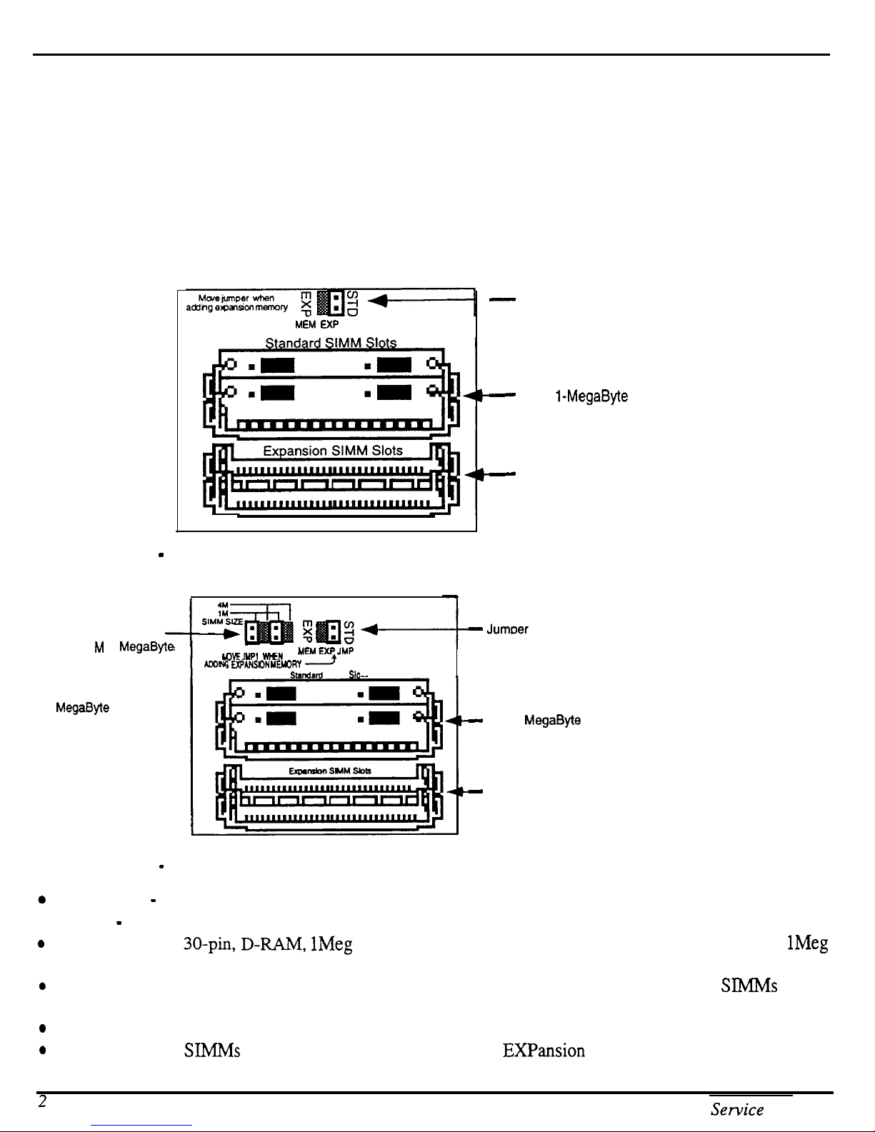
How to Tell Which Rev Board You Have
The old rev board looks like this:
-
Jumper is connected for
M6.4 EXP JMP
STANDARD SIMM Memory.
Move to the other pins when
using Expansion SIMM Slots.
-
Two 1-MegaByte SlMMs
Figure 1 - Note the single jumper above the SIMM slots.
The new rev board looks like this:
SIMM Size Jumpers (2)
are set to 1 M (1
SIMMS). Move the
jumpers to the 4M
positions when changing
to 4
MegaByte
MegaByte
SIMMS.
Figure 2 - Note the two different jumpers above the SIMM slots.
y- - -
DEJYPI
i EXPANSON
-.. M
WN
YMRY
Smndrfd
IEM EXF’JMP
)
SIMM Sk
-
Expansion slots are empty
-
Jumoer is connected for
STANDARD SIMM Memory.
Move to the other pins when
using expansion SIMM slots.
-
Two 1 MegaByte SlMMs
-
Expansion slots are empty
0
Keyboard - SIMMs may be installed by customer.
l
Rack - SlMMs must be installed by Repair Stations because the lid must be removed.
0
The ASR uses 30-pin, D-RAM,
9 or 4Meg x 9 parity SlMMs). The ASR will not accept static RAM or ROMs.
0
We do not recommend using parity SIMMs (designed for IBM PC compatibles). These SIMMs may not
operate properly, and may cause damage to the ASR.
0
We recommend using SIMMs with an access speed of 80 nanoseconds or faster.
0
When installing SIMhJs be sure to move the jumper to the Expansion position.
2
1Meg
x 8 or 4Meg x 8 (Macintosh-type) non-parity SIMMs (not
ASR Sewice Manual
1Meg
x
Page 7
Important
l
If SIMMs are installed in a less than optimal configuration (see pp.
71-72),
the display will read SIMMs
IN WRONG SOCKETS after booting. If this message is displayed, you should power off and check the
SIMMs configuration.
l
SIMMs that have GAL (gate array logic) or PAL (programmable array logic) chips on them may be too
thick to fit into the standard sockets that are used on the ASR. Even if the SIMMs with
GALS
or
PALS
fit, they will draw too much power and certain configurations (i.e. 2M x8 SIMMs) will not work
properly.
l
See Important Information About SIMMs, p. 67.
THE DISK DRIVE
Transporting a unit
We do not, under any circumstances, recommend the insertion of an actual disk during transport. Only
transport the unit with the drive empty. Please do not ship an ASR or a replacement disk drive in a box
packed with foam peanuts. If you must use foam peanuts, wrap the entire unit in plastic first. Foam peanuts
may cause severe damage to the disk drive or keyboard.
What disks to use
It is very important to use double-sided, double-density (DD) or high density (HD) 3.5” micro-floppy disks.
The ASR writes information to every track on a disk, so it is imperative that the disk be of superior quality.
Disks that have been pre-formatted for MS DOS are not always reliable and should not be used.
Testing the Disk Drive
The best way to test the disk drive is by formatting a disk. When a disk is formatted, the ASR reads and
writes every track on that disk. If the formatting fails, the disk itself may be faulty. Try formatting another
disk before determining that the disk drive is faulty. Unlike some computer systems, the ASR does not
automatically discard bad sectors when formatting. The entire disk must be good for successful formatting.
There is an exception, a disk that has been pre-formatted for MS DOS may be able to be formatted for use in
an ASR and still not work reliably in the ASR.
e
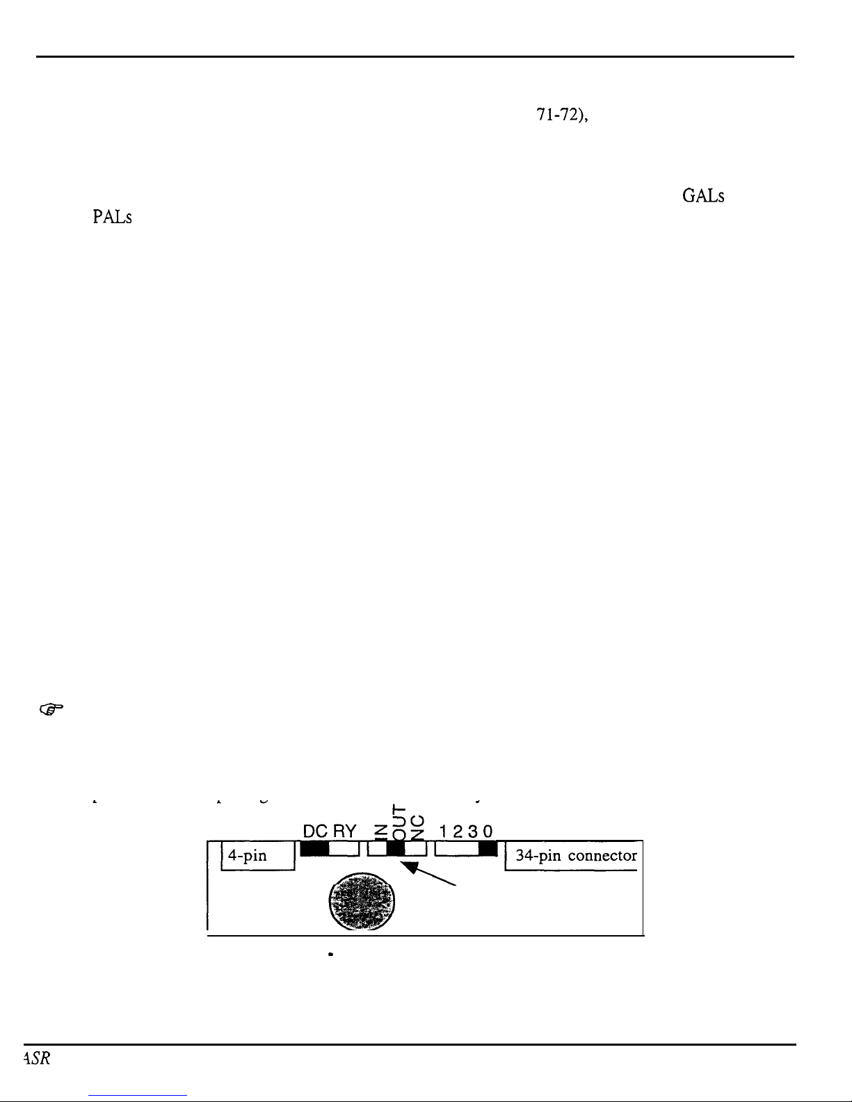
A few different disk drives were used in the ASR: two types of Panasonic drive and one Sony drive.
Make sure that when you install a new Panasonic disk drive that the switches on the rear of the drive are set as
shown in Figure 3. On some Panasonic disk drives, the Drive Select Switch has only two positions instead of
four. The drive select should always be set to zero (0). If the drive cable is too short, you may also need a
new 34 pin cable when replacing a Panasonic drive with a Sony drive.
-Make
sure that this
switch is in the middle!
Figure 3 - Rear view of Panasonic Disk Drive
4SR
Service Manual
3
Page 8
Imoortant
e
Customers may complain that their ASR will not read some of their disks.
Density
(I-ID)
disks that have been formatted as Double Density (DD) on a DD drive in a unit such as an EPS,
Please be aware that High
EPS-16 PLUS, or a Macintosh Plus will not be recognized in machines that have an HD drive. This would
include the ASR, as well as an IBM PC or clone. Disks that have been pre-formatted for MS DOS are not
always reliable and should not be used.
e
On early units, removing the disk drive causes the disk drive bezel to break.
The Sony 420-l disk drive has a jumper block. The correct jumper settings are shown in figure 4.
Figure 4 - Correct Sony 420-l jumper settings
CF In keyboard units, some plastic on both the wheel cover and end cap has to be removed. Replacement
disk drives now come with a template and instructions for cutting the plastic on the wheel cover for older
units. See the information included with the new drive.
UNIT SOUNDS DISTORTED
l
If the Peak LEDs on the Input Level are always on, this usually indicates a blown fuse.
l
Setting the loop end point before the loop start point can cause the unit to make funny sounds. To check
this, select the sound that this is occurring on, then select the wavesample: press Edit, underline WS, and
play a key that plays the offending sound so that the display shows a number (rather than ALL). If no
number will show up, underline layer and choose a new layer, then try again. Press Wave, press right
arrow repeatedly until the display shows LOOP START. Note the percentage number in the parenthesis.
Press right arrow again until the display shows LOOP END and note the number in the parenthesis for
loop end. The loop end number must be larger than the loop start number. No factory sounds are shipped
this way, so this is most likely to occur on sounds that the customer has created or modified.
l
Make sure that the cable for each jack board is connected properly.
l
ESP download failures will show up as either a “SYSTEM ERROR xxx” or as the outputs playing “dry”
without any effects, with garbled effects, or with no sound at all. If sounds set to DRY sound fine, but
sounds with effects don’t, replace the digital board.
l KEYBOARD ONLY: If there is distortion on the tail of every sound, and the serial number of the unit is
between 10970 and 11700, replace the analog board.
l
If a sample that the customer recorded into the ASR sounds distorted or there is a click in the beginning
and/or end of the sound, check the A/D chip on the Analog board:
a)
Make sure that NOTHlNG is plugged into either of the ASR Audio Input jacks.
b)
Keyboard only: Make sure that the MIC/LINE switch is in the LINE (down) position.
C
)
Make sure that the Input Level pot is turned fully down (counterclockwise when facing the back of
the ASR).
d) Press Command, then Env 1.
4
ASR Service Manual
Page 9
Imnortant
e)
Press the right arrow button until the display shows DC OFFSET.
fj’
Press
Enter*Yes.
The display should show: LEFT=
+/-0000x
RIGHT=
+/-OOOOy
g)
If one or both of the values is 32,767 replace the analog board.
h)
In a properly functioning unit, the reading should not be greater than 20 counts from zero (+/-
00020). If the values exceed this: RACK: Replace the analog board.
KEYBOARD: You can adjust each pot on the analog board to be as close to zero as possible:
1)
You can adjust the pots (these are the only two pots on the analog board) with your fingers. You
must reach under the unit and locate the pot that needs to be adjusted. Locate this visually before
grabbing it. Slowly turn the pot clockwise (to the RIGHT) to increase the reading, or counter-
clockwise (to the LEFT) to decrease the reading.
2)
If they cannot be adjusted within the allowable range of +/-00020, replace the Analog Board.
i) Press
Cancel*No
to stop the test. The display shows: DC OFFSET
FUSES
l
A system error may be the result of blown fuses. Check the fuses first.
0
If the Peak LEDs are always on, fuses may be blown. When the sample peak LEDs are on, it is usually a
blown fuse.
.
Fuse Ratings (as of October, 1995)
UL rated fuses
IEC 127 rated fuses Where Used
(lOOV, 12OV,24OV)
(230V units only)
Fl and F2
1.6A
fast blow
Tl
.OA slow blow
Analog
F3 and F4 4.OA
fast blow
F4.OA
fast blow +VD Digital/Display/KbdSCSI/DI-10
F5 1.6A
fast blow
F1.6A
fast blow Display
F6 and F7
l.OA slow blow Tl.OA slow blow
AIldOg
F9 2.OA
fast blow
F2.OA
fast blow Line Fuse
The 20-pin
Keyboard/KPC
Simulator Ribbon Cable
When reconnecting this cable to the digital board, make sure that the striped side is aligned with pin 1 and that
the cable is not mis-pinned. If the cable & r&-pinned or installed backward, fuses F3 and F4 on the power
supply board will blow. NOTE: If one fuse blows, the other will blow also; you must replace both.
Customer Thinks the Unit is Broken
l
Version 240 KPC software, when you hold down up arrow and press down arrow, numbers would
scroll instead of going to the halfway point. A new keyboard with 2.41 fixes this problem. See Software
Notes.
0
The sampling “Level Detect” screen should be looked at as an averaging meter and not as an accurate or
realtime signal. Some customers were concerned that their units were broken because the level detect
indicator bounces all over the place or does not respond to peaks.
.
Customers may complain that their ASR will not read some of their disks. Please be aware that High
Density (I-ID) disks that have been formatted as Double Density (DD) on a DD drive in a unit such as an
EPS, EPS-16 PLUS, or a Macintosh Plus will not be recognized in machines that have an HD drive. This
would include the ASR, as well as an IBM PC or clone. Disks that have been pre-formatted for DOS
are not always reliable and should not be used.
ISR Service Manual
5
Page 10
Important
MECHANICAL ISSUES
Keyboard:
two 6-32s into main board heat sink, and self-tapping into the extrusion. The 6-32s were eventually
changed to
Keyboard:
unit. The wheel cover was modified on later units to prevent this.
Keyboard: If the mounting posts for the wheel brackets break, call ENSONIQ for a new wheel cover
that has the posts reinforced.
Keyboard: Early units may have buttons sticking or keys clacking. To make sure that buttons don’t
stick on later units, a M4xlOmm hex head set screw was added to the extrusion rail that the
keypad/display board mounts to locate the keypad/display board properly. Don’t remove this set screw.
Rack:
screws are not used. Nylock screws have a patch of nylon on the threads for greater holding power.
Rack: On ASR Racks with serial numbers between 10000 and 10500, the rack ear screw PEMs (screw
mounting standoffs) may fall inside the unit.
W
ASR Case (Avoid Stripping Screws)
Be careful when assembling or disassembling any part of the ASR. Avoid over-tightening screws when
repairing a unit! Use no more than 8
made of aluminum extrusions and steel. Some parts are held in place by screws that
tighten into aluminum mounting rails that are part of the case. When replacing any of these screws, it is
possible to over-tighten the screws and strip out a hole.
Originally, three different types of screws were used in the ASR keyboard base pan 832s,
8-32s,
so that there are now only two different types of screws.
On early units, you may break the disk drive bezel when removing the disk drive from the
On Rack units, use a drop of Loctite on screws that hold the circuit boards in place if nylock
incMbs
of torque when tightening any screw. The ASR case is
W
High-Retention Force Connectors (Repair Technicians Label)
Inside the ASR is warning/information label just for you. We wanted to let you know that we use high
retention force connectors in the ASR. This means it is very difficult to remove a connector by just pulling.
We recommend the use of a scribe, screwdriver or similar object when disconnecting cables. Watch out for
them, and please don’t pull on the wires!
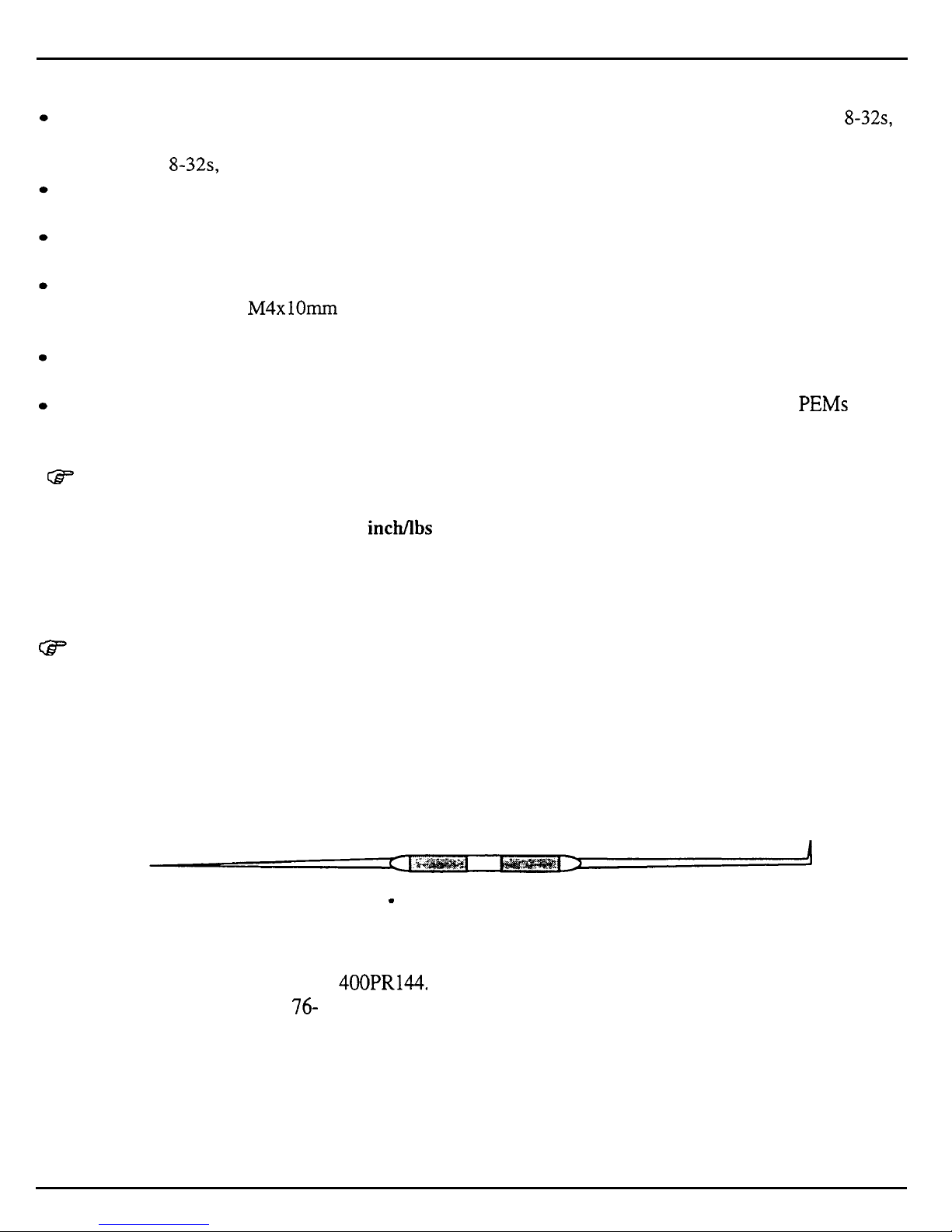
We have found that some units develop further problems once a module has been changed. This
may be
a result of improper handling of cables. We suggest removing all cable connectors using the angled end of a
scribe (see Figure 5).
Figure 5 - Correct tool for removing cables
Scribes can be found in the following catalogs:
l Techni-Tool catalog part number 400PR144.
l Newark catalog part number
76-
15 10.
6
ASR Service Manual
Page 11
Important
GF OEX-6sr CONNECTOR ON ASR KEYBOARD AND ASR-88 CAUTION!!! IMPORTANT!!!
The OEX-6sr should never be plugged in or unplu,,
OOed
with the ASR power on, as this could damage the
ASR. The 8-pin mini-DIN connector on the rear panel of the ASR should only be used to connect the
OEX-6sr Output Expander to the unit. This connector does not simply supply audio outputs and signal
ground and, therefore, cannot be used to generate separate outputs without the OEX-6sr. The ASR
generates digital signals that must be converted externally. The signals present on this connector include
digital control signals and
+/- 15VDC.
Improper connections to these signals could easily damage the
ASR or any external device connected.
HOW THE ASR WORKS
W
This section should help you understand what each module in the ASR does. Reading this may help you
decide what module is faulty by just knowing the ASR system better.
The ASR- 10 is a powerful self-contained computer system. It offers users the ability to accomplish many
tasks, some of these are:
l Sampling audio information from external sources
l Resampling its own audio output
l Adding digital effects to samples
l Sequencing
l Digital audio track recording
l Disk storage and retrieval
The ability to accomplish these tasks makes the ASR-10 a complex system.
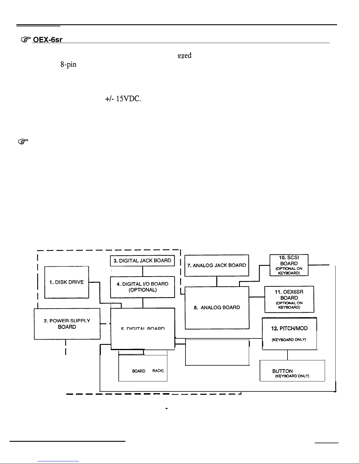
Figure 6 shows the ASR-10’s main components as a complete system.
WHEEL ASSEMBLY
m
ONLY)
9. KEYPAD/DISPLAY
BOARD
I
6. KEYBOARD
13. PATCH SELECT
I
(KPC
BOARD
ON
RACK)
I
BmON
BOARD
I
I
(KFfBOARO ONLY)
I
--------s-s
,,-----a
Figure 6 - ASR Block Diagram
ASR Service Manual
7
Page 12
Important
The block diagram also represents the modular design of the ASR-10. Each one of the main components
represented in the diagram can be replaced, if necessary, without disturbing the other components in the
system. Looking at the diagram you see:
1. Disk Drive
2. Power Supply Board
3. Digital Jack Board
4. Digital I/O Board
5. Digital Board
6. Keyboard (KPC Board on Rack)
Data storage and retrieval device.
Converts AC voltages to regulated DC and unregulated AC and DC to
be distributed throughout the system.
Connections to facilitate the use of the optional digital I/O board. MIDI
jacks, CV pedal jack, and footswitch jacks
Optional board that enables the ASR-10 to use digital audio data directly
from a digital source, such as DAT. It also allows the ASR-10 to output
digital audio data directly to a digital recorder, such as DAT.
The engine of the ASR-10. It has the microprocessor, the sound
processor, operating system memory, sound memory, effects processor,
and floppy disk controller. It also has the circuitry to control all inputs
to and outputs from the system.
Sends performance information (note on, note off, pressure) to the ASR-
10 digital board. Also handles communications to and from the
keypad/display board.
7. Analog Jack Board
8. Analog Board
9. Keypad/Display Board
10. SCSI Board
ll.OEX6sr
.12.
Pitch and Mod. Wheel
Board
Assembly
Has the input pre-amp circuitry on it, all of the audio inputs and outputs
(except for OEX-6).
Converts analog audio signals into digital audio signals and passes them
to the digital board. Converts digital audio signals to analog audio
signals and supplies them to the audio outputs and headphone amplifier
Transmits button presses to the digital board through the keyboard, and
receives display data from the digital board through the keyboard. See
figure 7 for further details.
Allows access to SCSI devices for storage and retrieval of data, and disk
track digital recording. It is an optional board on the ASR- 10 keyboard.
Optional board on the ASR-10 keyboard. Adds three additional stereo D
to A converters for six additional analog outputs.
Transmits pitch and modulation wheel movements to the digital board. It
is not included on the ASR-10 rackmount.
8
ASR Service Manual
Page 13
ImDortant
13. Patch Select Button Board
Transmits patch select button presses to the digital board. It is not
included on the ASR-10 rackmount.
The ASR-10 was designed with the analog and digital sections on different boards, and the analog and digital
jack boards separate, for some specific reasons.
l
Only the digital board requires a four-layer circuit board so there is a cost savings using a two-layer board
for the analog section.
l
It is easier to break the connections between the analog board and the digital board to install the optional
optically isolated SCSI board. This ensures that no matter how much digital noise is induced on the digital
board due to SCSI, it won’t reach the analog section.
l
Having separate jack boards allows the interface points with the outside world to be placed away from
circuitry that can be damaged by Electra Static Discharge that can be introduced at these points. This
decreases the instruments susceptibility to damage from ESD.
Keyboard and Rack Similarities
The Keyboard and the Rack use the same operating system (OS.) disk. The ASR-88 uses different EPROMs.
All circuit boards except the keypad/display board are the same for both the keyboard and the rack. However,
there are physical differences that will require you to specify for which unit you are ordering parts.
Instead of a Poly-Key keyboard assembly, the Rack has a KPC simulator board. The KPC simulator board
passes information between the keypad/display board and the digital board (like the keyboard does for the
keyboard unit). In the rest of this manual, whenever you see “keyboard,” substitute KPC simulator for the
Rack and keyboard adapter board for the ASR-88 (except where otherwise noted). The ASR Rack has the
OEX-6sr Output Expander and SCSI Interface (SP-3) built-in. These two expanders are options for the
Keyboard unit. Digital I/O is an option for all ASR models. The ASR-88 has 16Meg of RAM standard, and
SCSI. The ASR-88 has a keyboard adapter board instead of a KPC board.
Communications Path
It is important that you completely understand the communications path
of
the ASR.
Please read this
carefully.
The ASR digital board, keypad/display board and keyboard are complete computer systems in themselves,
each with its own microprocessor and operating software. The modules communicate with each other using
serial communication ports. Whenever a key is played on the keyboard, for example, the keyboard assembly
microprocessor transmits this information to the microprocessor on the digital board.
The keypad/display board communicates with the digital board through the keyboard. Whenever the digital
board wants to put a message on the display, it sends the message to the keyboard which then passes it on to
the display. Whenever a button is pressed on the control panel, the keypad/display board’sends the message to
the keyboard which, in turn, passes it on to the digital board.
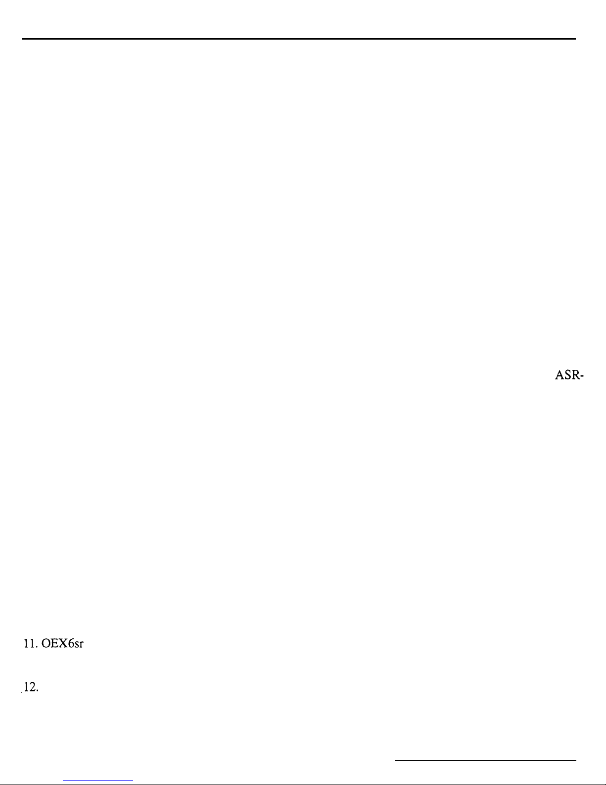
The communications path is shown in Figure 7. The digital board communicates with the keyboard over a
two-line asynchronous interface carried by the 20-pin keyboard ribbon cable. The keyboard communicates
with the keypad/display board over a three-line synchronous interface that is carried over to the digital board
via the 20-pin ribbon cable, then up to the keypad/display board via the 24-pin ribbon cable.
ASR Service Manual
9
Page 14

Imoortant
Due to the complexity of the modules involved, it is often difficult to determine which module is at fault when
a communications problem occurs.
KEYPAD/DISPLAY BOARD
1
DIGITAL BOARD
DATA DATA CLOCK
IN
/
I
OUT OUT
DATA DATA
IN
ASYNCHRONOUS
OUT
PORT
DATA
DATA CLOCK
I
Figure 7 - Communications Path
I
24 PIN DISPLAY
CABLE
If a communication problem occurs (i.e., no display or no response to button presses or keys), it could be
something as simple as a bad cable, or it could be a problem in one of the modules. To help you identify a
faulty module, a Communication Test Board is available from ENSONIQ Customer Service*. The
Communication Test Board simulates the operation of the keyboard and can be used as a “known good”
module in place of the keyboard for troubleshooting.
*This is the same communications test board that was sent out to service centers in 1990 to troubleshoot
polypressure keyboard problems.
IMPORTANT!
When using the Communication Test Board, keep in mind that it is sensitive to static discharge. Handle the
board by the edges and store it in the anti-static shipping bag when not in use. Do not let the board short out
when testing, place an insulator (cardboard, paper, etc.) underneath it,
Attaching the Communications Test Board
If an ASR has a communications problem, turn the unit off and unplug the 20-pin keyboard ribbon cable from
the digital board at connector J7. Plug the 20-pin ribbon cable from the Communication Test Board into
57.
This will eliminate the keyboard as a variable. Turn the system on. If the communications problem persists,
you know the keyboard is not at fault. If communication is restarted, however, the keyboard is at fault.
There is one further complication. Since the communications path between the keyboard and keypad/display
board is routed through the digital board, there is a remote possibility that the printed circuit connections
10
ASR Service Manual
Page 15
Important
between the two connectors are defective. If you have an ASR that has a problem communicating with its
keypad/display board, you may want to verify continuity between the connectors on the digital board.
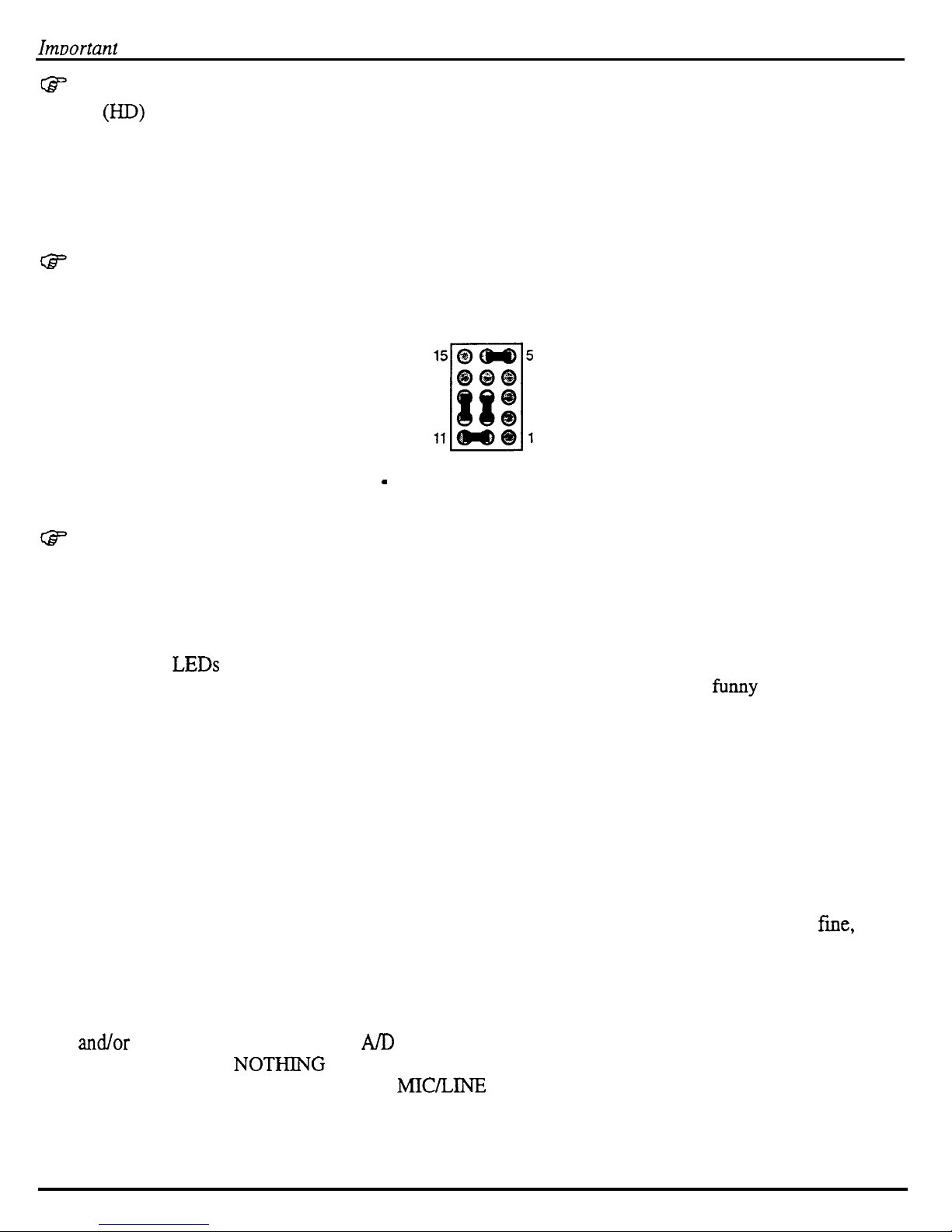
Turn off the power and unplug the 20-pin ribbon cable from the ASR digital board at J7 and the ASR 24-pin
display cable from the digital board at Jl. Using an ohmmeter, verify continuity between the following points
on the digital board:
57 (20~Din
connector)
J 1
(24-Din
connector)
Pin 1
to
Pin 9
Pin3 to Pin 10
Pin 5
to
Pin 11
TROUBLESHOOTING
Often the faulty module in an ASR can be determined through normal use. Sometimes, it is difficult to
isolate the problem. The following flowcharts can help you diagnose units that appear dead (no display).
When troubleshooting an ASR, always disconnect any expansion devices that may be present (such as the
SCSI Interface or OEX-6sr Output Expander). This will prevent a faulty expander from complicating your
troubleshooting. Remember, when you take out the SCSI board, connect the analog board to the digital
board via a 34 pin ribbon cable to J6 on the digital board and Jl on the analog board.
The following pages include troubleshooting information:
Pao,e
Problem
12
AC Line Voltages
13
Power Supply Voltage Check Points
14
ASR with Incorrect Analog Power Supply Voltages (flow chart)
15
ASR with Incorrect Digital Power Supply Voltages (flow chart)
16
Display Self-test Chart
17
ASR with No LEDs Lit (flow chart)
18
ASR with All LEDs Lit, No Display (flow chart)
19
ASR Foot Switch and Patch Select Inputs
20
ASR-88 Keyboard
ASR Service Manual
Page 16
Checking the Power Supply
CHECKING THE POWER SUPPLY
Some ASR-10 problems may be related to a faulty power supply, transformer or line filter. You should
check these before troubleshooting the rest of the unit. Measure continuity across all the fuses to
make sure they are not blown.
Make sure that all the cable connections are secure and correct. Plug the ASR-10 in and turn it on.
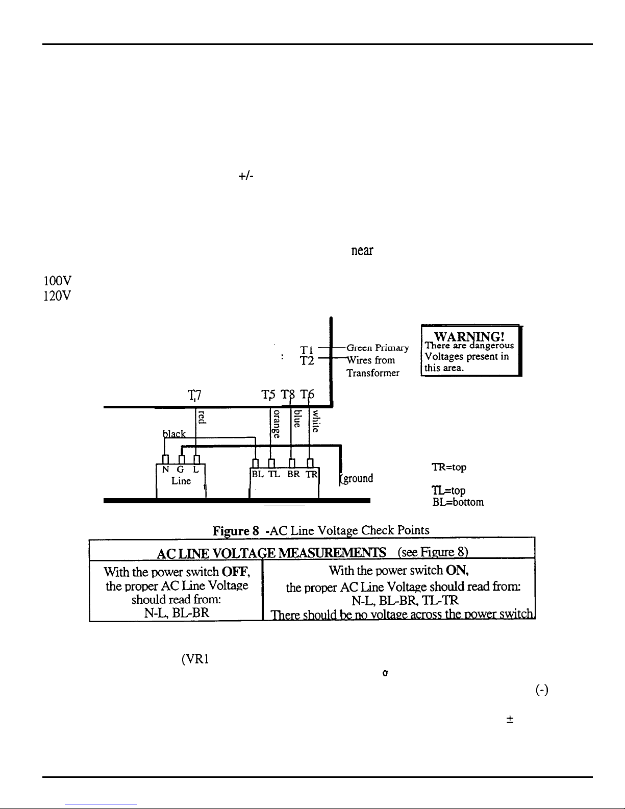
After it has warmed up for five minutes, begin to test the voltages at the points shown in Figures 8 and 9.
It is normal for Line Voltage to vary
+/-
10%. If the voltages vary outside the allowable limits, follow
the procedure described under TESTING THE POWER SUPPLY UNLOADED (pp. 14-15) before
replacing it.
The voltage and part number of the chassis mount transformer are on the label on the top of the
transformer. The power supply part number is silk-screened near the center of the power supply PC
board. The chassis mount transformer part numbers for the ASR-10 are:
1OOV
1450000722 230V
12OV
1450000342 240V
1450000352
1450000932
These lugs are on the
power supply board.
v
NOTE: Wiring
is the same for
the ASR-10 Rack
Filter 1
Power Switch
green wire
Tground
I
to
case)
TR=top
BR=bottom right lug
TL=top left lug
BL=bottom left lug
right lug
Rear of ASR-10 Keyboard Unit
Analog Board Regulator Voltages
There are seven regulators (VRl through VR7) attached to the analog board heat sink. On the keyboard
(J
version, you can easily check to make sure that they are generatin,
voltages are silkscreened onto the analog board next to the regulator name. Place your ground
the correct voltages. The correct
(-)
probe
on the tab of VR5. To measure the output, place the other probe on pin 3 of the regulator (when the
regulator legs are closest to you, pin 3 is the right leg). It is normal for the voltage to vary f 5%.
12
ASR Service Manual
Page 17
Checking The Power Supply
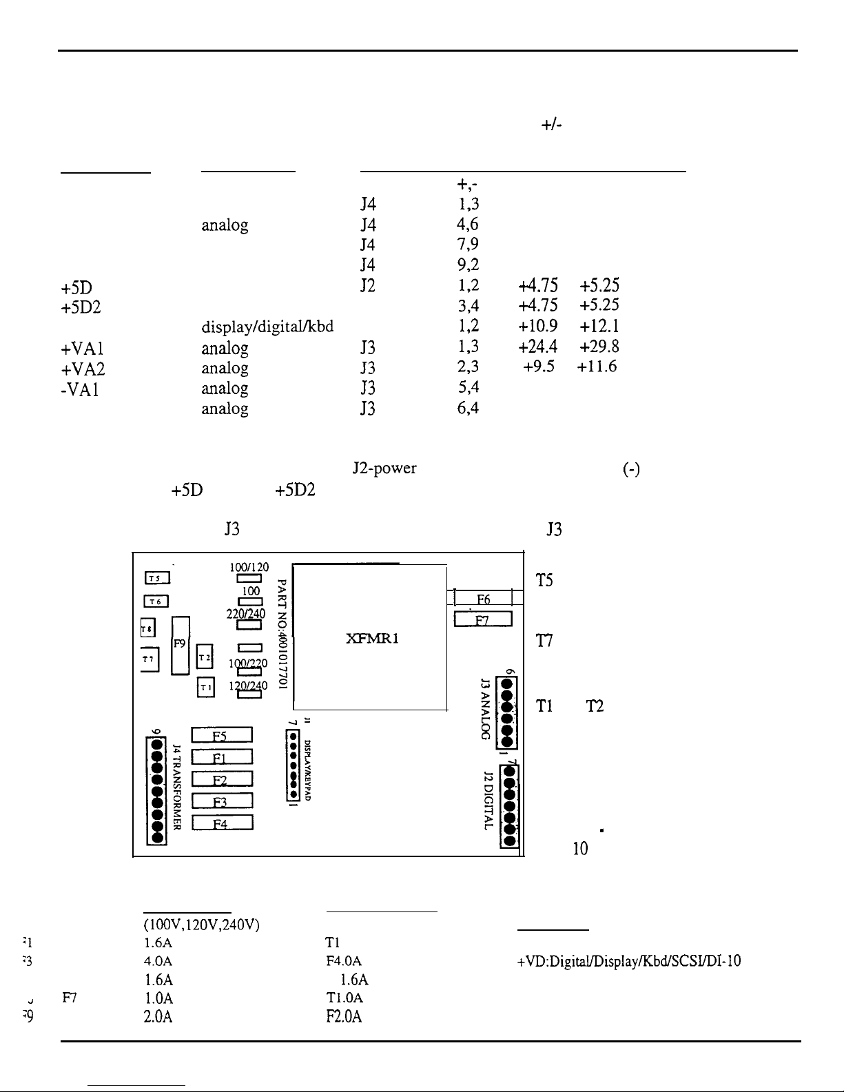
POWER SUPPLY VOLTAGE CHECK POINTS
Below are the voltage ranges for proper operation of each fully loaded supply and the pins to read across
with the voltmeter (see Figure 9). It is normal for line voltage to vary +/- 10%.
Designation
Where Used
Connector Pins Allowable range Units
+,-
Digital Supply
digital
54
193
18.7 to 22.8
VACrms
Analog Supply
XXil0g
54
496
17.1 to 20.9
VACrms
Display Filament display
54
799
5.1 to 6.2
VACrms
Display Offset
display
54
92
-25.0 to -30.6
VDC
+5D 1
digital
52
172
i4.75 to
+5.25 VDC
+5D2
digital J2
3-4
+4.75
to
+5.25 VDC
+VD
display/digital/kbd J 1
12
+10.9
to
+12.1 VDC
+VAl LUlal0g
53
193
+24.4
to
+29.8 VDC
+VA2
aIMlog
53
2,3
+9.5
to
+11.6 VDC
-VA1
Wtl0g
53
534
-27.6 to -33.8 VDC
-VA2
TilldOg
53
694
-10.9 to -12.1 VDC
J2 was marked Xl on some early versions of the power supply board. These voltages can also be
measured on the digital board (near the J2-power connector) with the ground
(-)
probe on the digital
board heat sink:
+5D
1 at FB3; +5D2 at FB2; and +VD at FB 1.
On keyboard units, the 53 power supply voltages may be measured at 53 of the analog board.
:l
and F2
:3
and F4
.,
and
F7
29
li%”
El
22OL240
0
120
t F6
1
Gil
T5 orange
T6 white
T8 blue
‘I7 red
Tl
and T2 are green
transformer wires
Figure 9
-
ASR- 10 Power Supply Board
UL rated fuses
(lOOV, 12OV,24OV)
1.6A fast blow
4.OA
fast blow
1.6A fast blow
l.OA slow blow
2.OA
fast blow
Fuse Ratings (as of October 1995)
IEC 127 rated fuses
(230V units only)
Where Used
Tl
.OA slow blow Analog
F4.OA
fast blow
+VD:DigitaL/Display/bdfSCWDI-10
F
1.6A
fast blow Display
Tl.OA slow blow
Analog
F2.OA
fast blow
Line Fuse
ASR Service Manual
13
Page 18
Checking the Power Supply
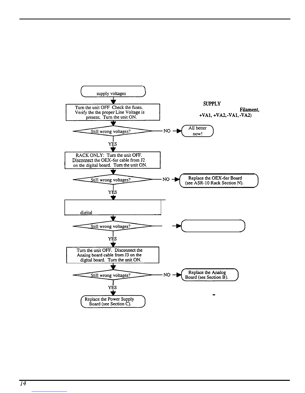
TESTING THE POWER SUPPLY UNLOADED
If the power supply readings exceed the indicated tolerance it is possible that a defective component one
of the other boards is drawing the power supply down. In this case, you should test the power supply
unloaded before proceeding. This involves unplugging circuit boards from the power supply one at a
time to see what board might be causing the incorrect readings. The procedure for doing this is shown in
the flow charts, figures 8 and 9.
/
Incorrect analog power
\
INCORRECT ANALOG POWER
SUPPLY VOLTAGES
(Analog Supply, Display
+VAl, +VAZ, -VA& -VA2)
Fiient,
Disconycf
the OEX-6sr cable from J2
$1
Turn the unit OFF. Disconnect the
Analog Jack board cable from J4 on the
dieital
board. Turn the unit ON.
NO
Replace the Analog Jack
Board (see Section G).
Figure 10
Incorrect Analog Power
Supply Voltages
-
14
ASR Service Manual
Page 19
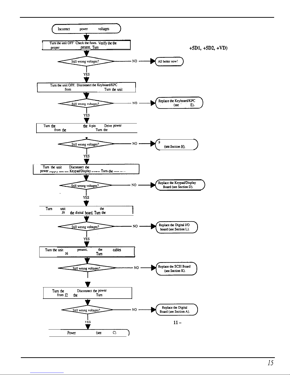
Checking The Power Supply
Incomct
digital power supply voltags
INCORRECT DIGITAL
TumtheunitOFF Checkthefuscs.
Vetifythetbe
pmpcr Line Voltage is present Turn the unit ON.
POWER SUPPLY VOLTAGES
(Digital Supply +5Dl, +5D2, +VD)
NO+=)
Simulator cable from J7 of tbe digital board. Turn the unit
Simulator (see Section E).
Turn tbc unit Off. Disconnect tbc Cpin Disk Drive power
cable
From
tbc keypad/display board. Turn dx unit ON.
I
l
Replace the Disk Drive
T-0+(
(see section IQ.
Turn tbz unit Off. Disconnect the ‘I-pin cable between the
power supply and the KcypxVDisplay Board. Turn the unit ON.
Turn the unit OFF. If present. disc-t tbc Digital I/O
cable fmm 19 on he didtal board. Turn the unit ON.
I
Turn the unit
OFF. If
prescn~
disc-t
tbc
SCSI
cables
fmm J4 and 16 on the digital board.
TUTI
the unit ON.
YES
v
Turn bc unit Off. Disconnect the
pwa
supply
cable fmm I2 on the digital board. Turn the unit ON.
Replace tbe Power Supply Board
(WC
Section C).
Figure
ll-
Incorrect Digital Power
Supply Voltages
ASR Service Manual
I.5
Page 20
Checking the Display
DISPLAY SELF-TEST MODE
When the keypad/display is receiving power from the power supply but is not in proper communication
with the digital board, the keypad/display board enters self-test mode. In self-test mode, the display
remains blank until you press the buttons on the control panel. Pressing various control panel buttons
will cause the display to print characters, home the cursor, etc.*
Using Self-test Mode to Diagnose the Keypad/Display Board
1.
If the unit comes in with a blank display, but is in self-test mode (i.e., the display prints
characters when buttons are pressed according to the chart below) this indicates the problem is either
the digital board or the communication link between the digital board, keyboard and the
keypad/display board. Before replacing anything, check all connections, particularly the 20-pin cable
to the keyboard.
If pressing buttons causes only the leftmost character of the display to change, this usually indicates a
defective cable connection (20-pin ribbon cable) between the digital board and keyboard or possibly
a bad keyboard.
2.
If the unit is in self-test mode but the display does not respond according to the chart below,
the problem is most likely in the keypad/display board. If certain buttons do not function properly
during normal ASR-10 operation, test them while the display is in self-test mode.
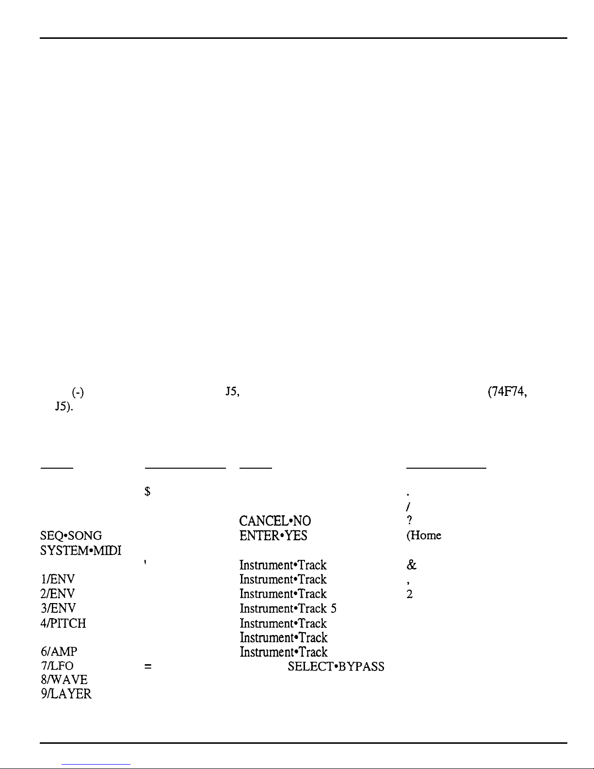
If you can’t isolate a problem that seems related to the display, the display can be forced into Self-test
mode using the following procedure. With the power off, face the front of the unit, then jumper the
minus
to
(-)
side of C83 (located below
JS).
On power up, the display will stay in self-test as long as the jumper is connected, allowing you to
J5,
the digital jack board connector) to pin 1 of U64
(74F74,
next
check the keypad/display board independently. The chart below details how the control panel buttons
are mapped in self-test mode:
Press:
LOAD
COMMAND
EDIT
INSTRUMENT
SEQ*SONG
SYSTEM~MIDI
EFFECTS
l/ENV
1
2lENV 2
3fENV 3
4/PlTCH
S/FILTER
6lAMP
7fLFO
8fWAVE
g/LAYER
O/TRACK
up Arrow
Displav Reads:
8
$
1.
3
9
I
+
0
1
6
7
<
=
(Home Cursor)
(Home Cursor)
*
3.
Press:
Down Arrow
Left Arrow
Right Arrow
CANCEL*NO
ENTER*YES
Instrument-Track 1
Instrument*Track
Instrument*Track
2
3
Instrument*Track 4
Instrument*Track
5
Instrument*Track 6
Instrument*Track
Instrument*Track
7
8
EFFECT SELECT*BYPASS
SAMPLE
RECORD
STOP/CONTINUE
PLAY
Displav Reads:
4.
;
;Home Cursor)
Space
&
;
(Home Cursor)
5.
4
2.
>
0.
5
6.
16
ASR Service Manual
Page 21
Checking the Display
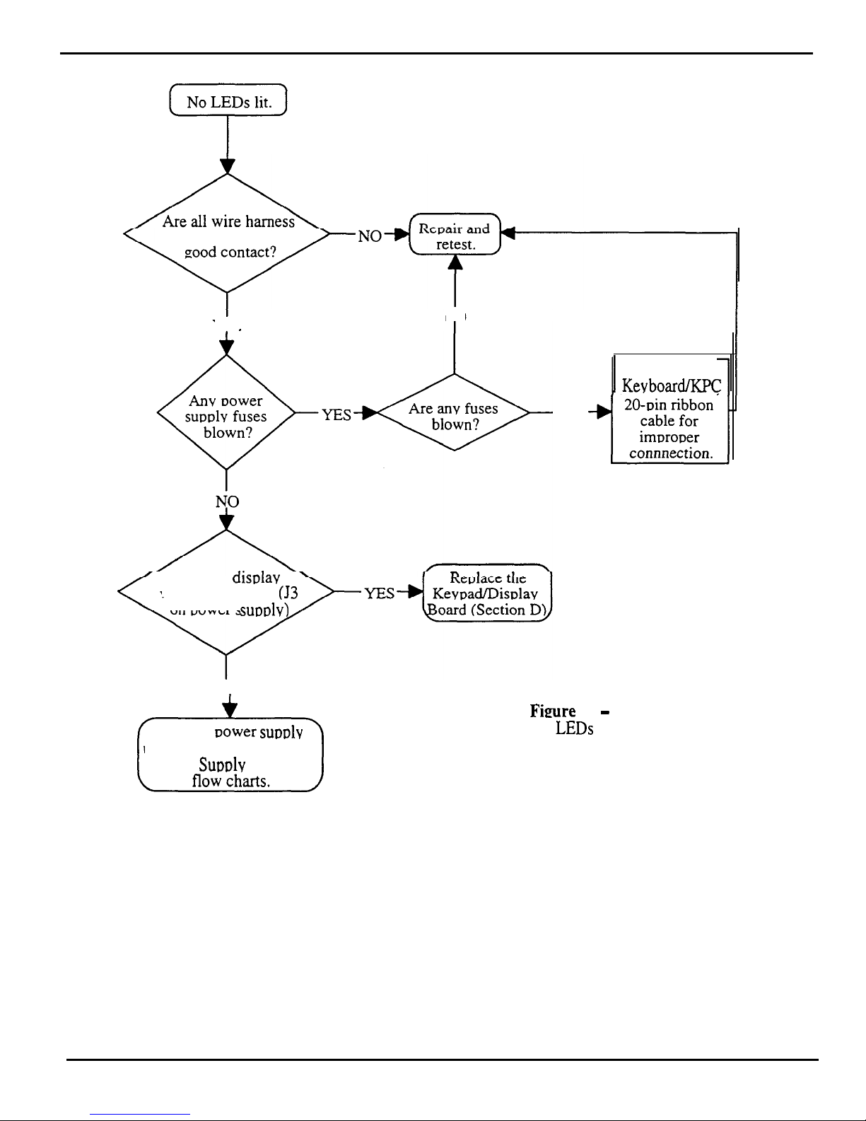
TROUBLESHOOTING AN
ASR-10 WITH NO LEDS LIT
connections making
YES
NO
I
Check
Kevboard/KPC
YES
Are the disulav
voltages correct?
(53
on Dower
suoolv)
NO
Test the
Dower
su~ulv
unloaded. Go to Incorrect
Power Supolv Voltages
Fimre 12
-
No LEDs Lit
ASR Service Manual
17
Page 22
Checking the Display
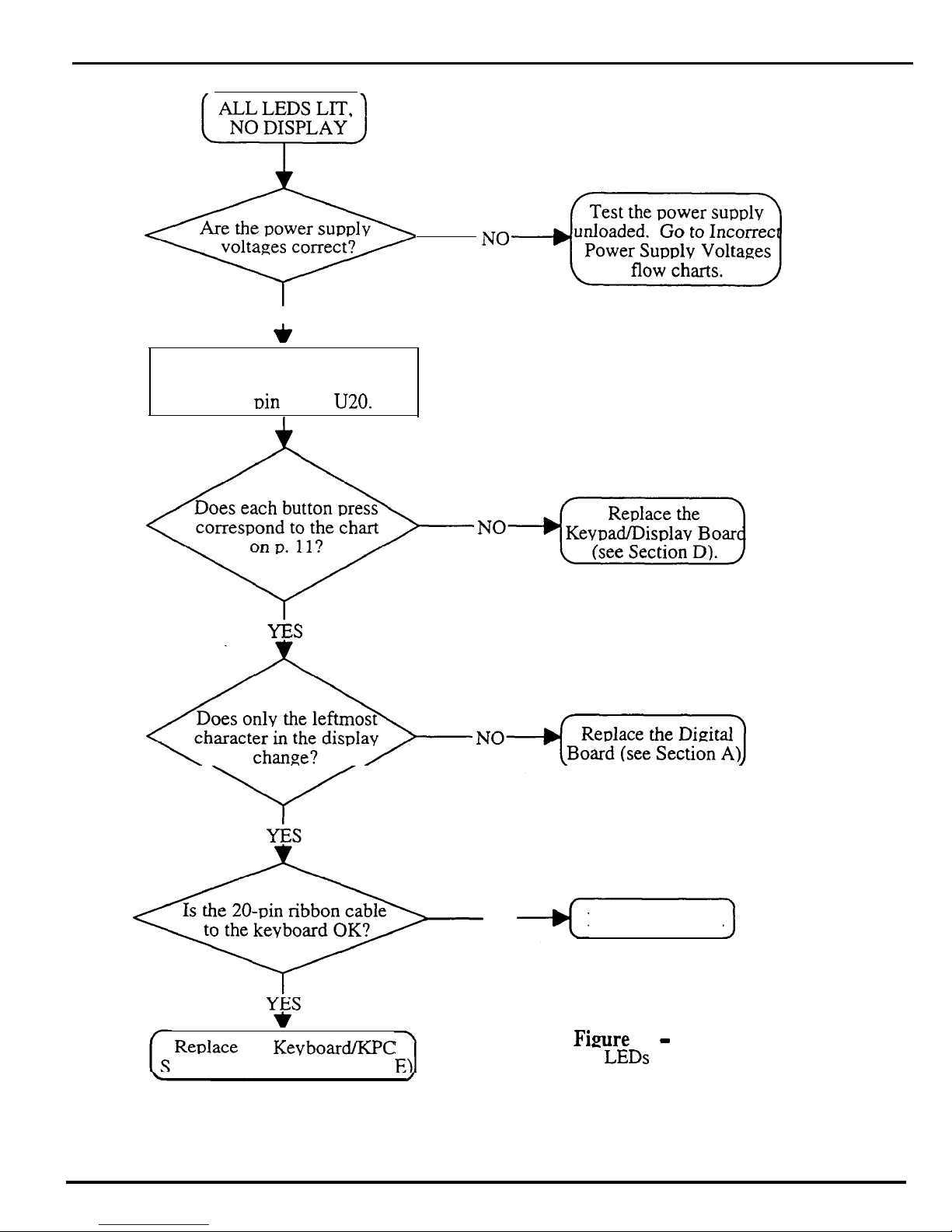
ALL LEDS LIT,
NO DISPLAY
z
Are the power supply
voltages correct?
YES
*
Force the unit into self-test mode
Jumper the negative (left) side
Cl9 to
Din
13 of
U20.
TROUBLESHOOTING AN ASR-10
WITH ALL LEDS LIT, NO DISPLAY
Reulace the KevboardXPC
imulator board (see Section
18
NO
Repair and retest.
Figure
13
-
All LEDs Lit, No Displav
ASR Service Manual
Page 23
Kevboard and Footswitch
Inuuts
The ASR-10 Keyboard and the KPC Simulator Board
The Poly-Key
-r~
Pressure Keyboard on the ASR-10 (and the KPC simulator board on the Rack) is a
complex module that contains its own computer and software. So, when necessary, you will be
swapping it out as a whole unit. Display information sent to and from the digital board is processed
through the keyboard/KPC simulator. What might appear to be a frozen display, therefore, could be a
bad keyboard/KPC simulator. For more troubleshooting hints, see Communications Path p. 10.
The 20-pin Ribbon Cable
(Kevboard/K.PC
Simulator)
When reconnecting this cable to the digital board, make sure that the striped side is aligned with pin 1
and that the cable is not r&-pinned. If the cable & mis-pinned or installed backward, fuses F3 and F4
on the power supply board will blow. NOTE: If one fuse blows, the other will blow also; you must
replace both.
ASR-10 Foot Switch and Patch Select Inputs
Foot Switch Jack
A single pedal foot switch (like the SW-5) plugged into the Ft. SW. jack is always a Sustain pedal.
When a dual foot switch (piano-type, like the SW-lo) is plugged into the Ft. SW. jack, the right pedal is
always a Sustain pedal and the left pedal is programmable (OFF, FX MODSRC, SAMPL YES, or
STOP/CONT).
To check to see what the left foot switch is set to, press Edit, then press
System*MIDI
repeatedly until the display shows LEFT Ff SWITCH=OFF (default).
Although the foot switch jack is mounted on the digital jack board, the foot switch signals go to the
keyboard, where they are sensed by the keyboard microprocessor.
Patch Select Jack
A single pedal foot switch (like the SW-5) plugged into the Patch Select jack causes the ASR-10 to think
that the left patch select button is always down
(X0).
The single pedal acts as the right patch select
button (XX).
When a dual foot switch (piano-type, like the SW-lo) is plugged into the patch select jack, the right acts
as the right patch select button and the left pedal acts as the left patch select button.
ASR Service Manual
19
Page 24

ASR-88 Kevboard
ASR-88 KEYBOARD
The ASR-88 uses the same keyboard as the KT-88 that has “bubble” switches, the ASR-88 keyboard is
only different in the adapter board. Instead of mechanical switches, this keyboard has a molded rubber
bubble under each key. The keyboard circuit board has conductive carbon contacts printed on it (which
appear as small black strips under each key). Each rubber bubble also has small conductive carbon dots
printed on the inside. The bubbles are made in strips which attach to the circuit board using small nubs.
The nubs on a strip are pushed through holes in the circuit board, in order to hold the strip in place.
As a key is pressed, it forces the bubble down until the carbon dots on the bubble hit the carbon contacts
on the circuit board. This completes the circuit. The circuit has two contacts per key, a back contact and
a front contact. The back contact closes first when a key is pressed, then the front contact closes. We
measure the amount of time between when the back contact closes and when the front contact closes.
This tells us how fast the key was hit, making the keyboard “velocity-sensitive”. In other words, we can
tell how hard the musician is playing and can adjust the volume and brightness of the sound in response
to the playing style. Each bubble switch also has a diode in series with it for proper circuit operation.
Key Response Problems
Although bubble switches are more reliable than mechanical switches, there are still many things that
can go wrong with this keyboard. If the bubble switches don’t switch in the proper order (first the back
contact, then the front contact) or if the switches don’t make clean contact, several problems can occur.
These include:
l Keys that don’t sound at all
l Erratic keys that “chatter” as they are played, held or released
l Keys that sound much louder than other keys
l Keys that sound much quieter that other keys
These problems can be caused by several things, including:
l Open or shorted traces on the circuit boards
l Bad or dirty carbon contacts on the circuit boards
l Bad or dirty carbon contacts on the bubbles
l Tom or otherwise damaged bubbles
l Bubble strips that are installed backward
l Interference between the key and the bubble (such as foreign material trapped between the key and
the bubble)
l Improper alignment between the key and the bubble
l Bad diodes
Usually failures will fall into two categories; either one key is bad, or a group of keys is bad. If a group
of keys is bad, all the keys may be grouped together (usually a group of eight) or they may be spread
across the keyboard (usually every eighth key).
If keys fail in a group of eight or every eighth key fails, the problem is most likely an open or shorted
trace on the circuit board or a problem with the keyboard processor board (that is mounted to the bottom
of the keyboard).
20
ASR Service Manual
Page 25
ASR-88 Keyboard
If only one key is bad (or if groups of keys are bad but not in groups of eight or every eighth key), the
problem could be any of the above. The first thing to do is remove the key and see if there is anything
obviously wrong with the bubble:
Look for damage to the bubble itself.
If the bubble is damaged, the circuit board must be removed so the strip can be replaced.
Check that the bubble strip is seated flat against the circuit board.
If the strip is improperly seated, use an appropriate tool (a straightened paper clip works well; don’t
use a sharp tool as it can puncture the rubber strip) to force the nubs on the strip into the holes on the
circuit board. The strip should lay flat against the circuit board.
Check that the bubble isn’t backward. If installed correctly, the deeper of the two bubble
contacts should be at the rear of the keyboard.
If the strip is in backward, remove the circuit board, pull the strip off the circuit board, turn it around
and reinstall it.
Remove any foreign material caught between the bubble and the key.
See if the plunger on the key makes proper contact with the top of the bubble.
If the piunger on the key forces the bubble down unevenly (with one side of the bubble being much
higher than the other side), loosen the screws that hold the circuit board in place and slide the circuit
board over slightly to better align the key and the bubble, then re-tighten the screws,
Check that both diodes for that key are inserted properly (the banded end of all diodes should
face the same way).
If a diode is in backward, the circuit board must be removed and the diode must be unsoldered,
reversed and re-soldered.
Check that both diodes for that key are working properly.
Select the “diode check” setting on an ohmmeter and test the diodes. The diode should conduct
when the negative (black) lead of the ohmrneter is on the cathode (banded) end of the diode and the
positive (red) lead of the ohmmeter is on the anode (unbanded) end of the diode. The diode should
not conduct when the negative (black) lead of the ohmmeter is on the anode (unbanded) end of the
diode and the positive (red) lead of the ohmmeter is on the cathode (banded) end of the diode. If a
diode is bad, replace it with a lN914B diode.
If there is no obvious problem, remove the circuit board:
l Examine the circuit board for short circuits.
These are usually caused by solder bridging. Touch up any shorts with a soldering iron and/or razor
knife.
l Look for open traces.
These usually occur at the break-away points along the edge of the board and near the connectors.
Solder a wire jumper in place to fix any broken connections.
l Remove the bubble strip and clean both the circuit board contacts and the bubble contacts
with alcohol and a cotton swab.
Allow them to air dry before putting the bubbles back on the circuit board.
If after all this the keyboard still doesn’t work properly, replace the entire keyboard assembly.
ASR Service Manual
21
Page 26

ASR-88 Keyboard
Pressure Response Problems
The ASR-88 keyboard, like the KT-88 and TS-12, has mono pressure response. This allows a
modulation effect to increase as you press harder on a key. Pressing harder on any key will affect all
other keys. To produce mono pressure, two pressure sensitive strips are inside the keyboard assembly.
Pressing on a key exerts a downward pressure on the strips. Two strips are used because of the large
88-
note span. The signals from the two strips are combined by the mono pressure circuit that resides on the
keyboard processor board that is mounted to the bottom of the 88-note keyboard near the wheel
assembly. Note that it is normal for pressure response to vary depending on the number of keys being
pressed.
If pressure response is not working properly, check the alignment of the pressure strips, and make sure
they are securely connected to the keyboard adapter board. Replacement of the pressure strips is not
practical on this keyboard assembly, if there is damage to the pressure strips, replace the entire keyboard
assembly.
22
ASR Service Manual
Page 27

Error Messages
ERROR MESSAGES
Occasional error messages are not unusual, and unless they become chronic, they are not a cause for
concern. It is important to realize that these messages are diagnostics and do not necessarily indicate a
problem. These messages were designed to help our software engineers in the development of the
software, not as hardware diagnostics.
Software Messages
The following error messages could be caused by software:
IDnU
Descrintion
ID#
Desctiution
013
software error in voice assignments
132
chk instruction register out of bounds
016
poly or mono pressure events sent to VC
133
trapv instruction ovefflow error
020 unknown button event
134 privilege violation
048 parameter error
135 trace
049 layer error
137 line 1111 emulator
080
bad buffer to MIDI
138 spurious interrupt
128 bus error
139 unused vector
129 odd address error
192
load all data error (from MIDI or card)
130 divide by zero
193
keyup
playback error
13 1llegal instruction
194
out of SDBs error
Digital Board Problems
The following error messages could be caused by a problem on the digital board:
005
could not synchronize audio input
033 bad ESP chip
006
could not synchronize audio input
034 bad
ESPFWM
019 Bad
OTTO
interrupt
040* bad ESP error
032 bad download
145
unknown DUART interrupt error
Analog or Digital Board Problem (clock comes from analog board, make sure there are no analog
fuses blown and that the analog power supplies are O.K.)
009
No
LRCLK
input to 68302
MIDI or Main Board Problems
The following error is usually caused by too much incoming MIDI data. It also could be caused by a
problem with the keyboard.
144
out of buffers
Disk File Operation Errors
The following error messages could be caused by software:
ID# DescriDtion
ID# Descrintion
00 illegal block # during read/write
07
current DIR & FAT info in buffer is not valid
01 Missing End of File marker
08 not enough space to save file
02 Premature End of File marker
10
file size > free blocks on device
03 file linked list points to unused block
15
no free blocks found on
the
diskette
04 file linked list points to bad block
16
illegal fat block # load was attempted
ASR Service Manual
23
Page 28

Error
05
06 current info in FAT buffer is not valid data 32-35 and 40*-44 NEC PD 72069 errors
*Please note that error 40 error 040 are separate errors. Error 40 is always a disk controller or disk drive related
problem. Error 040 is always an ESP problem. In the case of error 040 the problem will always be an ESP
problem, in the case of error 40 the problem can be the disk drive controller (located on the digital board) or a
disk drive problem. Replace the disk drive with a known good drive first. If the error still persists, than replace
the digital board.
The following errors could be caused by a bad disk or disk drive:
09 block write attempt failed
11
12
The following errors could be caused a bad external SCSI cable or a SCSI termination problem:
18
20 scsi last command ignored
2 1
MessaPes
current info in DIR buffer is not valid data 17 file size greater than limit = 33 Mbytes
13
directory save verify error
14
device id pcb load/save error
operating system pcb load/save error
scsi command not complete/no disconnect ret
scsi check condition error
fat save verify error
22 possible disk drive index pulse problem
The following special message is not an error message:
for further explaination.
Not an EPS device. See the SCSI section of this manual
24
ASR Service Manual
Page 29

Sofhyare Notes
ASR-1 O/88
SOFIWARE
NOTES
The O.S. version on the disk can be easily updated (call ENSONIQ Customer Service for the latest O.S.
version). You cannot copy the O.S. to a disk onto which you have already saved instruments or
sequences, but not the O.S. Attempts to do so will result in an error message.
To Check the ASR-10 Software Version:
l Press Command, then Env 1. The display shows NO COMMANDS ON PAGE.
l Repeatedly press the left or right arrow button until the display shows SOFIWARE
INFORMATION.
l Press Enter-Yes. The display shows RAM VERSION = X.Xx.
l Press
EntereYes.
The display shows ROM VERSION = Y.YY.
l Press Enter-Yes. The display shows KEYBOARD VERSION ZZZ. For the Rack, this will
always show 1.
Keyboard Software
In keyboard version 2.40 software, when you hold down up arrow button and press down arrow
button, numbers would scroll instead of going to the halfway point. A new keyboard with keyboard
software version 2.41 fixes this problem (released 16 March 93).
On March 16, 1993, Keyboard Software Version 2.41 went into production. Version 2.41 addresses
problems that were inherent in version 2.40. The problems that were addressed are:
l Rapid button presses (e.g. direct dialing or holding inc/dec to center a parameter value) could cause
any of the following symptoms:
1)
Garbled display. For example: message not centered properly in the display, characters
missing or repeating in a message. Subsequent messages are displayed properly.
2)
Missed buttons. For example: holding down the up arrow button and pressing the down
arrow button to center a parameter could cause unit to miss a button-up, which would make
the parameter value scroll to the extreme high or low end of its range. Subsequent button
presses are handled properly.
3) Display/Button lock-up in extreme cases. Power off/on corrects problem.
ASR-10 ROM/DISK Compatibility Issues
The following chart summarizes the Operating System compatibility of the ASR-10 Keyboard and
Rack. The Rack was released with
1SOB
EPROMs and must have at least version 1.50 disk.
* From version 2.00 on,
the OS uses more space in RAM
than previous versions.This is
due to the Disk Tracks feature.
Version 3.50 ROMS are for
the ASR-88 only.
Figure 14 - ROM and disk Compatibility
ASR Service Manual
25
Page 30

So&are Notes
Special note on making copies of the Operating System (O.S.) disk:
The code that loads the O.S. from disk at bootup is stored in the ROMs.
1 .OO ROMs made some
assumptions about the location and format of the O.S. on the disk. For that reason, there are some
limitations that we must impose when using the COPY OS TO DISK command to copy an O.S.
from one disk to another. Generally, if the O.S. that you are copying is the same version that you are
running with, you will have no problems. Where things get tricky is when you are copying an O.S.
that is different from what you are running with. Here are the rules:
O.S. That’s running:
1.00 thru 1.25
1.00 thru 1.25
1.50
1.50
1.60 and higher
1.60 and higher
O.S.
to c0I.w:
1.00 thru 1.25
Results/Rules:
OK
1.50 or higher DESTINATION DISK MUST BE EMPTY. Use a
freshly formatted disk as the destination, otherwise
system will report not enough space on disk.
1 .OO thru 1.25
DESTINATION DISK MUST BE EMPTY
AND
DESTINATION DISK MUST BE SAME DENSITY
AS SOURCE DISK. Use a freshly formatted disk as
the destination with same density as the source disk,
otherwise command appears to work but the system
was not copied correctly.
1.50 or higher
OK
1.00 thru 1.25 DESTINATION DISK MUST BE SAME DENSITY
AS SOURCE DISK. Otherwise the system is not
copied correctly. May get the message DISK
WRONG SIZE.
1.50 or higher
OK
Note: Version compatibility is not an issue if using the COPY DISK command.
To update O.S. Version on a floppy disk:
l Insert the disk containing the O.S. you want to copy (the source disk) into the floppy drive.
l Press Command, then SystemWIDI.
l Press the right arrow button until the display shows COPY OS TO DISK.
The OS. version on the disk can be easily updated (call ENSONIQ Customer Service for the latest O.S.
version). You cannot copy the O.S. to a disk onto which you have already saved instruments or
sequences, but not the O.S. Attempts to do so will result in an error message.
To Check the ASR-10 Software Version:
l Press Command, then Env 1. The display shows NO COMMANDS ON PAGE.
l Repeatedly press the left or right arrow button until the display shows SOFTWARE
INFORMATION.
l Press
l Press
EnteraYes.
EntereYes.
The display shows RAM VERSION = XXX.
The display shows ROM VERSION = Y.YY.
26
ASR Service Manual
Page 31

So&are Notes
l Press
EnteraYes.
The display shows KEYBOARD VERSION ZZZ. For the Rack, this will
always show 1.
Version 1.25 disk (released 8 FEB 93)
For ASR-10 Keyboards ONLY.
This disk is only compatible with 1.00 ROMS. This is not u typical O.S. Release?
This
OS.
update is intended for customers who have a keyboard with 1.00 ROMs but do not need or want the SCSI kit. (When they buy
SCSI, they automatically get 1.50 ROMs if they don’t have them.) This release provides them with a method of upgrading their operating
system without the expense of a ROM change. Because this was a patch to the existing 1.20 O.S. disk, there are some known problems
that still exist in this release. The purpose of this release is to address the serious problems that can cause a crash or corrupt data. No new
features are added.
SEQUENCER
Loading SINGLE sequences from disk corrupted parameters of sequence that was currently selected. The selected sequence inherited the
following parameters from the sequence being loaded: loop switch, tempo, time signature, sequence length in bars. Symptoms that would
show include: keeping new after track edit results in no data left on track or extra events on track, tempo mysteriously changing on
sequence, bar counters looping prematurely or beyond the actual end of the sequence data. Auto-locate malfunctioning on specific
sequence. This problem has been in existence since 1 .OO. It has been addressed in version 1.25.
QUANnZE
track had a problem that caused track cleaner to erase the track. Symptom will be that user quantizes, track auditions tine.
but
is erased on a keep new. Not extremely likely, but you will get some calls about this. The quantize problem has been around since the
EPS days, but the track cleaner (which was introduced in version 1.20) makes the problem much more visible. In version 1.05, an
improperly quantized sequence may have played tine but subsequent track edits or overdubs could crash the system or destroy other
sequence data. The quantize problem has been fixed in version 1.25, the track cleaner is still in place.
Attempting to change the length of a song track through the CHANGE SEQUENCE LENGTH command resulted in ERROR 129. This
command is not available for song tracks. The only way to change the length of a song is to edit song steps. If user attempts to run the
change sequence length command when a song is selected, version 1.25 now displays SELECT SEQUENCE FIRST message.
WAVESAMF’LE EDITS
l
Performing a command like FADE IN on a Stereo sample with STEREO LAYER LINK ON caused the ASR to stop recognizing WS
numbers when you play the keyboard.
Inc/dec
keys do not function properly for wavesample selection. This is a BIG problem introduced
in version 1.20 that can happen when you do any stereo wavesample command that gives you an audition. Wavesamples may appear in
both layers or may have “moved” from one layer to the companion layer. The only way to recover your instrument is to “rebuild” the
instrument layer/wave maps by creating a new instrument and copying over the wavesamples to the new instrument, then deleting the old
instrument. If you suspect this problem, here’s how you can check your stereo instruments for valid layer/wave maps:
1. With STEREO LAYER LINK ON, select the left layer, then select the wavesample field.
2. Use the up-arrow to scroll through all wavesamples. Verify all the wavesamples for that layer exist.
3. Repeat this on the same layer using the down-arrow. Any discrepancies indicate a bad layer map.
4. Select the right (companion) layer and repeat steps 2 and 3.
This problem has been addressed in version 1.25.
Also verify that no wavesample appears in both the left and right layer.
MISC
l
A low-level bug existed that could cause the system data to be corrupted. Due to the nature of this bug, the exact circumstances that would
cause a problem and the symptoms that would show up are entirely unpredictable. This has been addressed in version 1.25.
KNOWN PROBLEMS
J.N
VERSION 1.25:
The following problems are known to exist in version 1.25. If a customer has 1.00 ROMs and is reporting any of the following problems,
the 1.25 O.S. disk will
NOT
solve his problem. The only recourse is for the customer to upgrade to I .50 ROMs.
MERGE TRACK COMMAND incorrectly allows you to specify ranges. The ranges are ignored when the command executes and the
merge is performed over the entire track.
exists in version 1.25.
Version 1.50 no longer allows ranges to be specified for this command, but this problem still
AUDIO GLITCHES (distortion, loss of stereo phase) that occur intermittently when all sequencer tracks are playing. It is NOT voice
stealing or effects related. This is due to OTTO losing sync of the beginning of the sample. Low probability. NOT addressed in version
1.25.
TIME COMPRESS/EXPAND is still not 100% reliable. Some portions of samples may not compress or expand at all. Other sections
may compress too much. Particularly noticeable with jam loops. It appears that experimenting with the quality value can correct the
problem. (For example, a sample that would not compress at quality of 25 would compress at a quality of 26.) The algorithm is being
reviewed. A change should be forthcoming that at least reduces the chances of failure. (Note that the audition gives you an accurate
picture of what the compression/expansion has done, and keeping the old will leave the original wavesample intact.)
Also note that time
compression/expansion of stereo samples may result in loss of phase. (That’s the way it is.) Still a problem in version in 1.25
and
1.50.
Attempting to edit the KEY RANGE with the data slider for samples that have STEREO LAYER LINK=ON results in LAYER EDIT
NOT ALLOWED. Not addressed in version 1.25, use
incfdec
buttons or keyboard to set wavesample key ranges.
MACRO files will not load. Still a problem in version 1.25.
MACRO files will not save correctly. Saving a macro file to floppy disk results in display saying “SAVING ASR-10 OS.” This is a
display anomaly only, the O.S. is not being overwritten. Still a problem in version 1.25.
A problem exists in the logic that waits for Enter or Cancel to be hit. A typical example would be some floppy disk commands (COPY
OS DONE. ANOTHER?). We found that if the user does nothing for 60-seconds, the system will timeout and the timeout logic could
lockup the display. Still a problem in version 1.25.
ENTER PLAYS KEY feature does NOT exist in version 1.25.
ASR Service Manual
27
Page 32

Software Notes
Version 1.50 disk (released 28 JAN 93)
This release contains some minor improvements and fixes for problems that have been discovered since
the version 1.20 disk. The unit must have version
1SOB
O.S. ROMs to use this disk. This is the
original release for the Rack.
NEW FEATURE
l
ENTER PLAYS KEY feature has been added to this release. The Enter button can be used to trigger sample playback. For more details,
see the 1 SO Manual Addendum.
SEQUENCER
l
Loading SINGLE sequences from disk corrupted parameters of sequence that was currently selected. The selected sequence inherited the
following parameters from the sequence being loaded: loop switch; tempo; time signature; sequence length in bars. Symptoms that would
show include: keeping new after track edit results in no data left on track or extra events on track; tempo mysteriously changing on
sequence; bar counters looping prematurely or beyond the actual end of the sequence data. Auto-locate malfunctioning on specific
sequence. This problem has existed since 1.0.
l
QUANTIZE track had a problem that caused track cleaner to erase the track. Symptom will be that user quantizes, track auditions fine, but
is erased on a keep new. Not extremely likely, but you will get some calls about this. The quantize problem has been around since the
EPS days, but the track cleaner (that was introduced in version 1.20) makes the problem much more visible. In version 1.05, an
improperly quantized sequence may have played fine but subsequent track edits or overdubs could crash the system or destroy other
sequence data. The quantize problem has been fixed in version 1.50. the track cleaner is still in place.
l
Attempting to change the length of a song track through the CHANGE SEQUENCE LENGTH command resulted in ERROR 129. This
command is not available for song tracks. The only way to change the length of a song is to edit song steps.
change sequence length command when a song is selected, version
l
MERGE TRACK COMMAND incorrectly allowed you to specify ranges. The ranges are ignored when the command executes and the
1 SO
now displays
SELE(JT
SEQUENCE FIRST message.
merge is performed over the entire track. Version 1.50 no longer allows ranges to be specified for this command.
AUDIO
l
Audio glitches (distortion, loss of stereo phase) that occur intermittently when all sequencer tracks are playing. It is NOT voice stealing or
effects related. This is due to OTTO losing sync of the beginning of the samole. This has been addressed.
WAVESAMPLE EDITS
l
Attemotinz to edit the KEY RANGE with the data slider for samoles that have STEREO LAYER LINK=ON results in LAYER EDIT
NOT
l
ALLOWED.
Performing a command like FADE IN on a Stereo sample with STEREO LAYER LINK ON caused the ASR to stop recognizing WS
Addressed in version 1.50.
numbers when you play the keyboard.
- -
I I
1
Inc/dec
keys do not function properly for wavesample selection. This is a BIG problem introduced
in version 1.20 that can happen when you do any stereo wavesample command that gives you an audition. Wavesamples may appear in
both layers or may have “moved” from one layer to the companion layer. The only way to recover your instrument is to “rebuild” the
instrument layer/wave maps by creating a new instrument and copying over the wavesamples to the new instrument, then deleting the old
instrument. If you suspect this problem, here’s how you can check your stereo instruments for valid layer/wave maps:
1. With STEREO LAYER LINK ON, select the left layer, then select the wavesample field.
2. Use the up arrow to scroll through all wavesamples. Verify all the wavesamples for that layer exist.
3. Repeat this on the same layer using the down-arrow. Any discrepancies indicate a bad layer map.
4. Select the right (companion) layer and repeat steps 2 and 3. Also verify that no wavesample appears in both the left and right layer.
MACRO FILES
l
Macros would not load correctly. This has been fixed in version 1.50.
l
Saving a macro tile did not work. Trying to save a macro file to floppy disk resulted in display saying SAVING ASR-10 OS. Macro files
save correctly in version 1.50.
MIX
l
A problem was found with the logic that waits for
Enter
or
Cancel
to be hit. A typical example would be some floppy disk commands
(COPY OS DONE. ANOTHER?). We found that if the user does nothing for 60-seconds, the system will timeout and the timeout logic
could crash the machine. In version 1.50, the message is simply redisplayed after 60 seconds.
KNOWN PROBLEMS/OMISSIONS IN 1.50
. The following commands are currently
l
TIME COMPRESS/EXPAND is still not 100% reliable. Some portions of samples may not compress or expand at
disabled
in version 1 SO: COPY SCSI DEVICE and SCSI BACKUP RESTORE.
may compress too much. Particularly noticeable with jam loops. It appears that experimenting with the quality value can correct the
problem. (For example, a sample that would not compress at quality of 25 would compress at a quality of 26.) The algorithm is being
reviewed. A change should be forthcoming that at least reduces the chances of failure. (Note that the audition gives you an accurate
picture of what the compression/expansion has done, and keeping the old will leave the original wavesample intact.)
compression/expansion of stereo samples may result in loss of phase.
If user attempts to run the
all.
Other sections
Also note that time
Version 1.60 disk (released 25 FEB 93)
This release contains some minor improvements and fixes for problems that have been discovered since
the version 1.50 disk. The unit must have version
problems have been addressed in version 1.60.
STORAGE / SYSTEM
l
COPY SCSI DEVICE and SCSI BACKUP/RESTORE commands have been enabled,
l
COPY OS command would not work when trying to copy an operating system that was compatible with
version 1.60, these older versions can be copied provided the following rules
A.source
and destination disk must be the same density, and
28
1SOB
O.S. ROMs to use this disk. The following
I.00
are
met (othenvise an error message is displayed):
ROMS (1.00 thru 1.25). In
ASR Service kfanuul
Page 33

Software Notes
B. the destination disk does not already contain an operating system later than version 1.25 (i.e. 1 SO or 1.60).
We still recommend using the COPY DISK command if users want to copy an Operating System that is different from the one that is
currently running.
l
LOAD BANK or LOAD SONG file had a problem that could cause the machine to lock up or crash when loading songs into the ASR-10
if those songs or banks were originally created and saved on an EPS or EPS 16 PLUS. This problem has been fixed in 1.60.
SEQUENCER
l
Loading SINGLE sequences from disk still had a problem where parameters of the currently selected sequence or the sequence being
loaded could become corrupted.
This
was a timing problem that made it intermittent, depending on how busy the system was at the time
the load completed. Symptoms that would show include: keeping new after track edit results in no data left on track or extra events on
track, tempo mysteriously changing on sequence, bar counters looping prematurely or beyond the actual end of the sequence data. This
problem has been addressed in 1.60.
WAVESAMPLE COMMANDS
l
In version 1.60, a modification was made to TIME COMPRESS/EXPAND so that it is much more likely to find a valid splice point. This
will reduce the chance of a failure. Again, the audition does give you an accurate account of what the command has done. Let your ears
be the judge. Also note that time compression/expansion of stereo samples may result in loss of phase. This is due to differences in the
left/right data streams and is not a problem with the algorithm.
Version 1.61 disk (released 16 APR 93)
The unit must have version
1SOB
O.S. ROMs to use this disk. The following problem was discovered
in O.S. Version 1.60 and has been addressed in Version 1.6 1:
STORAGE/SYSTEM
l
The COPY FLOPPY DISK command can potentially erase all data on a SCSI hard drive. The conditions for this to occur are as follows:
> ASR-10 with SCSI interface.
> Hard drive connected with SCSI ID number of 0.
> Destination floppy for the COPY FLOPPY DISK command is not formatted or is a different format or capacity than the source
floppy.
> Hitting ENTER to the ERASE AND FORMAT DISK? prompt.
Workaround for O.S. Ver 1.60:
With so much to lose, it is best to avoid the COPY FLOPPY DISK command when a SCSI device is connected whose ID number is 0. For
those that are careful:
> Ensure that the destination floppy is formatted and is the same density as the source floppy. If unsure of the format of the source
floppy, proceed with caution.
> If the command prompts you with the ERASE AND FORMAT DISK message, hit CANCEL. disconnect all SCSI devices, then retry
the command.
Version 1.61 fixes this problem. It is the only problem addressed by this release. No new features are added.
Version 2.5 1 disk:
ENTER PLAYS KEY:
The Edit/System Midi, ENTER PLAYS KEY parameter incorrectly defaulted to C4+ after power-on, with no Instruments
loaded. The value was skewed by a semitone and the range incorrectly went from AO+ to C8+. The parameter now correctly
defaults to C4 and the range has been corrected to from A0 to C8.
Error 129 on Undefined ASMPLNAME:
Hitting the down arrow button would cause a system error 129 when on the ASMPLNAME parameter and the parameter
showed ASMPLNAME=UNDEFINED. This problem has been fixed.
COPY PITCH TABLE:
The COPY PITCH TABLE Command did not permit you to make additional pitch tables. Instead, the command overwrote
the current pitch table with a copy of itself, but with the name PITCH TABLE 3. This problem, which was introduced in
Version 2.01, has been fixed.
Invalid Sequencer Locate (GOTO) Requests
With Audio Track Data recorded, the first time you selected the Edit Seq Song, Bar or Beat value, and pressed Enter Yes
twice (to goto the last locate point -- but you have never used goto before, so this last locate point should default to 01.01). the
unit hung on . .
..Locating....
This problem has been fixed.
With Seq Track data (no Audio Tracks) recorded, the first time you selected the Edit Seq Song, Bar or Beat value, and
pressed Enter Yes twice (to goto the last located point -- but you have never used goto before, so this last locate point should
ASR Service Manual
29
Page 34

So*are
default to 01 .Ol), the unit located to an invalid location (Bar 384.04). Pressing continue caused the Bar count to run on to
999. This problem has been fixed.
Potential delay before entering SAMPLING or CREATE NEW INSTRUMENT:
If the ASR has to SHUFFLE memory before entering
on a display while memory was being shuffled, though it did collect button presses. Until the shuffling completed, the unit
appeared to be locked up. (Though it would recover and post-process the button presses). A shuffling data message has been
added and the system is placed into an orderly shutdown while the shuffling takes place. This addressed a similar problem
which occur if you ran CREATE NEW INSTRUMENT and shuffling had to occur.
Notes
Sarnplin
g,
no message was being displayed. The ASR remained frozen
Version 2.07 disk
STORAGE/DOS/SCSI
When saving an instrument or song fde to multiple disks, if you changed the floppy disk when prompted for “USE
MULTIPLE DISKS?” the wrong directory information would be
occurred). The result is that you have saved an invalid directory to the floppy disk that you just inserted.Most common result
is a “FILE OPERATION ERROR” on writes or reads to this disks, which must be reformatted. Fixed.
Loading
This could result in the loaded song name showing up as *UNDEFINED* or as instruments disappearing as soon as they
are loaded. Depending on what was already in memory, a crash may occur. Fixed.
Backup/Restore would hang if it had to create a sub-directory on the destination backup device. The backup could
never be completed. Usually occurs when doing a backup/restore to a SCSI device (not to floppies). Display hangs with
‘CREATING NEW DIRECTORY” message. Fixed.
Magneto Optical / Write Protect: A problem was found with magneto optical drives. Attempting to access the drive (even
for read operations) resulted in a “DISK WRITE PROTECTED” error message. Fixed.
Texel CD ROM drive start up problem: On power-up, the Texel CD ROM drive is not recognized properly. (Specific to
the nature that this drive wakes up). Normally, this is not a problem. However, attempting to do direct-dial macros with this
drive after power-up may lead to a system error. After rebooting (without a power-up) the drive worked as expected. Fixed.
first
file after a floppy disk change may use old FATS cached from previous disk.
used.
(The ASR was not aware that the disk change
MEMORY ALLOCATION / MANAGEMENT
A problem was found with low-level memory management. This problem would most likely manifest itself in units
expanded to 10 Meg or more. Symptoms are:
Lockup when attempting to save song and all seqs. Display would show “Shuffling Data”. Machine would never come out of
this state. More likely to occur when you had over 8 Meg of AudioSamples recorded or an instrument that was larger that 8
Meg. Fixed.
A problem was found in the RAM Track amalgamation logic where Audio Sample memory which was recorded over
would sometimes not to be returned to the system. Typically, any other Audio Sample editing (Delete Audio Sample,
Erase Audio Track, or additional RAM track recording) would cause this memory to be released again. However, if someone
had overdubbed until they ran out of memory, then kept new, the system would be in a state where there would not be enough
memory to do any more RAM track recording, even though the original AudioSample data was deleted. (Further attempts to
record would result in “NO ROOM FOR OPERATION”). Fixed.
You can create a situation that will lock the ASR in EDITING after KEEP NEW to an audio track that has been
punched-in on. This was a memory management problem particular to units with
SAMPLING / RAM TRACK RECORDING AND PLAYBACK
The first time that you enter sampling with REC SRC=DIGITAL, the system incorrectly allows you access to 119 MS
to Sampling Pre-Trigger time, instead of the 39 MS that it should Initialization problem, worked correctly on subsequent
sampling attempts. Fixed.
Exiting from Sampling in Stereo incorrectly turns off the Flashing Selected Audio Track yellow LED. This can leave
you in a mode in which both Audio Tracks are selected (ready for stereo recording), but only one yellow LED is lit. Fixed.
Drift between RAMTRACKS and Sequencer Tracks or sequencer slowing down when sampling main out at 30K.
This is a statistical problem that is specific to the main board. The problem is board-specific but has been addressed by
software, requiring a reduction in the pre-trigger time at 30K sample rate. The maximum pre-trigger time at 30K has been
reduced from 119ms to 93ms.
10M
or more memory. Fixed.
30
ASR Service
A4anual
Page 35

Soflware Notes
Sample playback “skipping” occurs when playing back RAMTRACK audiosamples or regular wavesamples which
are greater than 2M samples at 3OKHz. This problem can occur on any unit which has SM or
10M
or ram. All other
memory configurations work fine. The skipping usually starts at 43 seconds into the sample. The result is that the system will
play random chunks of its sound ram (including the Operating System space which sounds like bursts of noise). Fixed.
GENERAL / SYSTEM
ASR could have intermittent problems during song record or playback if the display is on the sequencer locate page.
This was a low-level error related to the display updating the current position in the song (error did not occur unless you were
on the locate page). This was a nasty problem that could be responsible for random crashes that occur during or after
sequence record or playback. For example, the “Gift of Gab” demo always crashed with an error 129 or 135. Any song file
could exhibit a problem. It all depends on the content of the song file. Fixed.
ENHANCEMENT ADDED:
The saving of SONG AND ALL SEQS is faster. Intelligence has been added to the SAVE SONG AND ALL SEQS
command to optimize the project file save time. Depending on the circumstances prior to the save, the time spent shuffling
data should be reduced by as much as 40%.
ASR-10 Version 3.00 Release Notes
The ASR-10 Version 3.00 Operating System (DISK only) has been tested and is ready for release to production. All ASR-IO
models (keyboard, rack, and keyboard with SCSI) will be getting this O.S. (p/n 8530000112) as a running change. The
EPROM update kit, which is included in the SP-3 and DI-10 service kits, will also pick up this change. For customer service
updates, the O.S. Disk requires version 1.50 ROMs. Any customer who is receiving this as a free upgrade should also receive
the new manual “Version 3 Operating System” (p/n 93 11006301). This manual now contains the operating instructions for
the SCSI interface and the DI- 10.
Note regarding Operating System size.
To support the
new
features added by this release, the Operating System has grown. You will see that the O.S. is 160 blocks
larger than our previous release, Ver 2.5 1. This means that with the Version 3.00 O.S.:
l On
bootup,
the FREE SYSTEM BLOCKS field will display a smaller number than Version 2.51.
l Banks that were within 160 blocks of the end of memory with Version 2.5 1 will no longer completely fit with
Version 3.00.
l Instruments that were within 160 blocks of the end of memory with Version 2.5 1 will no longer completely fit with
Version 3.00.
l Project files that were within 160 blocks of the end of memory with Version 2.5 1 will no longer completely frt with
Version 3.00.
l Rewriting the new O.S. to a disk that containing Version 2.51 will result in NOT ENOUGH DISK SPACE if the disk
did not have 160 blocks free.
The ASR-10 has gone though some major changes since it’s initial release. RamTrack and DiskTrack Recording (Version
2.0) DAT Backup (Version 2.5), and Importing Instruments from
AKAI
and Roland Libraries (Version 3.0). As we continue
to support the ASR- 10 by adding features, the Operating System must grow to
accomodate
the new software. This is the
tradeoff that must be paid. Note, however, that the Version 3.00 Operating System is compatable with the current Ver 1.50
ROMs. So a ROM upgrade is not required (assuming the unit is already running Operating System 1.50 or higher.)
New Feature: Auto Configure of
DiskTracks
The ASR-10 can now remember the Audio Track Configuration parameters when the unit is configured for DiskTrack
Recording. These parameters can be saved with Global Parameters. On the subsequent booting of the ASR-10, the unit will
prompt you to “CONFIGURE SCSI ATRKS?“. Hitting ENTER at this point will automatically configure the ASR-10 for
DiskTrack recording with your saved parameters.
See the Version 3 Operating System manual for details.
New Feature: Auto Prepare of Song Files
The ASR-IO will now automatically prepare the audio tracks for the song whenever a song file is loaded. On completion of
the song file load, the display will briefly show “PREPARING AUDIO TRACKS”. Note that song files that do not use audio
tracks will still briefly show this message while the song file is being scanned for audio track data. See the Version 3
Operating System manual for details.
ASR Service Manual
31
Page 36

Software Notes
New Feature: Import non-ASR Instruments
The ASR- 10 will now import and play sounds from the AKAI and Roland libraries. Unlike other programs that only load
wavesample data and loop information, the ASR-10 conversion takes place at the AKAI program level and the Roland Patch
level. Parameters such as velocity switching,layering, filters, etc are translated to native ASR- 10 instrument format. The
new imported instrument can now be saved or edited just like any other ASR-10 instrument. See the Version 3 Operating
System manual for details.
Additional Changes and Fixes:
In addition to the new features mentioned previously, the following problems have been addressed in Version 3.00:
Audio Track Recording - General
Invalid “OUT OF MEMORY” message on Record STOP. Hitting STOP during audio track recording could
result in an OUT OF MEMORY message even if free memory was available. This was a cosmetic problem
only. No data was lost. Fixed in Version 3.00.
System Error or lockup during KEEP NEW after audio track record.
A scenario could exist where the ASR-10 would crash with a system error (usually 129,215, 217), or the display is
frozen
problem that is fixed in Version 3.00.
Audio Track Recording - Stereo
A scenario could exist where the ASR-10 would crash with a system error (usually 129) or the display is frozen on
Version 3.00.
on . . . . EDITING . . . . .
. . . . EDITING . . . . .
when you stop recording or attempt to KEEP NEW after a stereo audio track record. Fixed in
after you KEEP NEW to an audio track record. This was a resource-allocation
DiskTrack Recording
DiskTrack overdub results in System Error 57 on KEEP NEW. A specific punch-in/out situation could result in
a System Error 57. This particular problem is unique to DiskTrack overdubs, when punching out on an existing
AudioSample. Fixed in Version 3.00.
Song File Saves and Loads
Loading song files saved with earlier Operating Systems cause lockups or System Errors. Song files that were
loaded and resaved across multiple operating systems may not have loaded properly. Defensive logic was added
to Version 3.00 to support song files saved across multiple Operating Systems.
Large song fdes created on disk Abnormal termination of sequencer recording could result in sequencer memory
being allocated but never released, resulting in a large song file. Version 3.00 fixes this problem.
Sound Voicing/Editing
Delete Wavesample removing all wavesamples in the layer. Certain layering situations could set up a case where
deleting a single wavesample resulted in all wavesamples within the selected layer being deleted. This problem
is fixed in Version 3.00.
Restrike Time parameter not working on stereo layers. Restrike time was not working properly when STEREO
LAYER LINK was set to ON. Fixed in Version 3.00.
Pops heard on dark, muted sounds when sustain pedal down. Exceeding the available polyphony could result in
slight pops which are noticeable on dark sounds. Version 3.00 addresses this problem.
Floppy Disk Commands
Invalid WRONG SIZE DISK message when using COPY FLOPPY DISK co
FLOPPY DISK, inserting an unformatted destination floppy disk brings up the following prompt: WRONG
SIZE DISK, even if it’s the correct disk density. This should happen only if the destination disk is a different
density than the source disk, but this error was appearing if the destination disk was not formatted on an ASR-
10. Fixed in Version 3.00.
mmand. When using the COPY
32
ASR Service Manual
Page 37

SOB-ware
Notes
FILE OPERATION ERROR message when using COPY FLOPPY DISK command. When the COPY
FLOPPY DISK Command is forced to erase all memory to copy a disk (such as when all memory is used), the
ASR displayed a FILE OPERATION ERROR the first time that the command was invoked. Running the
command again resulted in normal operation. Fixed in Version 3.00.
Improper formatting of destination disk when using COPY FLOPPY DISK command. If destination disk is a
PC-formatted disk of the same density, the disk could be re-formatted as a g-sector ENSONIQ disk, which may
or may not match the source disk. If it doesn’t match, the copy may fail. Version 3.00 now ensures that the
destination disk inherits the same format as the source disk if formatting is required.
Memory Management Changes
RAM AudioSamples still resident after ERASE SONG AND ALL SEQS command. Effective in Version 3.00,
the ERASE SONG + ALL SEQS now releases all memory allocated to RAM AudioSamples and their directory.
This is a logical extension to this command, since the RAM-resident AudioSamples are intended to travel with
the song (project) file. Note that disk-resident AudioSamples are unaffected.
System does not release all memory in response to “ERASE MEMORY- OK?” prompt. When running any of
these commands: COPY FLOPPY DISK, COPY SCSI DRIVE, BACKUP/RESTORE, DAT BACKUP
RESTORE, and SYSEX RECORDER, The system only deleted resident instruments. Version 3.00 now frees
memory allocated by the sequencer memory, RAM
AudioSamples,
and the SCSI (DiskTrack) cache buffers.
Attempting to load an instrument that is larger than memory that is free or allocated to existing instruments
results in an invalid instrument. Subsequent edits result in lockup.
The
ASR- 10 is allocating an instrument
slot for the instrument to be loaded. If, the instrument cannot fit in memory (even after deleting all resident
instruments) the slot allocated for the instrument is never reset.
This results in an invalid instrument which will
lockup the system if an attempt is made to edit it. This problem has been addressed in Version 3.00.
Attempting to load an instrument that is larger than memory that is free or allocated to existing instruments
results in sequencer memory being erased. The ASR-10 would release all sequencer memory in an attempt to
accomodate
the instrument being loaded. This has been changed in Version 3.00 so that sequencer memory is
not erased automatically by the instrument load function.
System Exclusive
Sysex get wavesample overview command not returning 2nd half of wavesample in the overview block The
WaveSample Overview sys-ex command was only loading a picture of l/2 of the WaveSample selected. Fixed
in Version 3.00.
Sysex Recorder function fails when system memory contains large RAM AudioSample data. Invoking the
Sys-
Ex recorder when a large amount of memory is being used up by RAMTracks failed to erase the RAMTrack
memory when the response to the MUST ERASE MEMORY OK? prompt was YES. Subsequent Audio Track
recording could result in invalid error messages. Effective in Version 3.00, erasing memory via the Sysex
Recorder command results in the ASR-10 purging all resident instruments, all sequencer memory (including
RAM AudioSamples and directory), and releasing the SCSI (DiskTrack) cache buffers.
ASR-10 Version 3.08 Release Notes
The ASR- 10 Version 3.08 Operating System (DISK only) has been tested and is ready for release to production. All ASR-10
models (keyboard, rack, and keyboard with SCSI) will be getting this O.S. (p/n 853oooOll3) as a running change. The
EPROM update kit, which is included in the SP-3 and DI-10 service kits, will also pick up this change. For customer service
updates, the
OS.
Disk requires version 1 SO ROMs.
Note regarding Operating System size.
The Operating System size has not changed since Version 3.00. Customers who are upgrading from Version 2.5 1 will see
that the Operating System requires 160 more blocks. (See Version 3.00 release notes.)
Software Changes:
No new features have been added to this release. This release addresses the following problems that have been reported since
Version 3.00:
ASR Service Manual
33
Page 38

Sofhvare
VOICE: MINI mode - no sound:
VOICE- TRIGGER or LEGATO mode - System Error:
IMPORT ROLAND - SOME PATCHES DO NOT IMPORT:
IMPORT AKAI - SOME PROGRAMS DO NOT IMPORT:
IMPORT AKAI: TICKS and POPS:
Notes
Layer glide mode = MINI was not dealing with simultaneous key downs properly. When multiple notes went down at the
same time, the result would be no audio output. (Granted, this mode dictates that you play monophonically. But if you
played a chord you should hear at least one note sound.) This problem originated in Beta version 2.72. It is now fixed.
Layer glide mode = TRIGGER or LEGATO could cause a system error 129 if multiple notes were played when the system
is first booted up. This was an initialization problem that would normally not cause a problem. The only reason that it
was found was a demo sequence from the disk DSAX-001 started with a piano chord programmed with the mode =
TRIGGER. Version 3.08 fixes this problem.
From Roland CD-ROM’s, if the CD was fairly full, some sounds would not show up in the directory listing, or they would
show up but attempting to load them would result in a file operation error. This has been fixed in Version 3.08.
Some CD-ROM’s in AKAI format may not show all of the programs in a particular volume. This can happen if the CD
ROM has wavesample files interleaved with program files within the same volume (instead of grouping all files of a
similar type.) This has been fixed in Version 3.08
Some AKAI sounds were importing with pops or ticks in the loop or at the beginning of the sample. The problem was an
offset in where the sample starts. Version 3.08 fixes this problem. A work-around in previous OS versions is to adjust the
sample start point by increasing it by 5. Same with Loop Position. This work-around should fix most ticks caused by this
problem.
IMPORT ERROR 133:
AKAI program Latin Percussion from IN-Vision Disk #6 Volume 7 caused an IMPORT ERROR 133. This error could
occur with other
IMPORT AFTERTOUCH ROUTING:
AKAI
Import always hard-coded aftertouch routed to Filter modulation amount as 0. This has been fixed.
IMPORT AKAI: WAVESAMPLE FINE TUNING:
Wavesample fine tuning on AKAI programs may cause a wavesample key group to be out of tune with the rest of the
keyboard. This has been fixed in Version 3.08. Note that AKAI samplers implement a wavesample fractional loop point
that our architecture does not support.
wavesample will play in tune until the loop end point is reached, then the loop will go slightly sharp or flat. No
workaround for this, it’s in the voice chip.
IMPORT INTO LAST BIN RESULTS IN NO FREE INSTRUMENTS MESSAGE
Importing into the last free instrument location of the ASR-10 results in a successful import but the command exits with a
“NO FREE INSTRUMENTS” message. The command was successful, but the message should not have been displayed.
This has been fixed in Version 3.08.
PHASER+REVERB EFFECT ALGORITHM REPLACED
The PHASER+REVERB algorithm could cause intermittent ticks and pops. This algorithm has been replaced in Version
3.08 to correct this problem.
A&I
imports as well, depending on the particular CD-ROM. This problem has been fixed.
If the program uses wavesample fractional loop points, the result is that the
ASR-10 Version 3.53 Release Notes
This operating system addresses the problem of global parameters not being loaded properly on
bootup.
SY
ASR Service Manual
Page 39

ASR Test Procedure
AM-TEST
PROCEDURE
The following procedure will aid in troubleshooting the unit. To do the following tests you will need a
MIDI cable, a Dual Foot Switch (model SW-5/10), and a Control Voltage Pedal (model CVP-1). The
ASR-10 should be connected to a sound system in stereo.
1.
Power Up and Load in Sounds
a)
Turn unit on. All the LEDs above the Instrument buttons should turn on and the display should
read ENSONIQ ASR- 10, (then for Racks and keyboards with SCSI:
SCSI INSTALLED,
SEARCHING FOR SCSI DEVICE), then PLEASE INSERT DISK.
b) Insert a factory ASR-10 O.S. disk. The display should read LOADING SYSTEM. The
keyboard unit will then display TUNING KBD - HANDS OFF. When the keyboard is tuned, all
LEDs should go off.
c)
The display should show FILE 1 TUTORIAL BNK (if it doesn’t, press the up or down arrow
button until it does).
d) Press Enter-Yes. The display will say LOADING <filename> while loading.
e)
The bank is done loading when the display shows BANK LOAD COMPLETED. The following
sounds will be loaded into the Instruments*Sequence Track 1 through 6:
Instrument 1 JM DRUMS
Instrument 2
DEMO PERCS
Instrument 3
MOOG POP 1
Instrument 4 HIGH STRINGS
Instrument 5
JM CLAV
Instrument 6
OB-8*
f) Play each sound briefly to make sure that they sound O.K.
*
If they don’t sound O.K., see the Distorted Audio section near the front of this manual.
2. Keyboard Test
(ASR-10/88
Keyboard Only)
a)
Select OB-8 (Instrument*Sequence Track 6).
b)
Play a chromatic scale across the entire keyboard. Press each key down only until normal key
travel ends. Do not press into pressure zone.
Verify that no pressure effect occurs.
c)
Press the key into the pressure zone and verify that pressure causes a change in volume.
*
Failure indicates a keyboard problem.
3. Headphone Check
a)
Plug headphones directly into headphone jack.
b)
Play a few notes to check for stereo and sound quality.
*
If there is a failure, check the connection to the analog jack board.
4. MIDI Test
a)
Connect MIDI OUT to MIDI IN with a MIDI cable.
b) Press Command, then Envl.
c)
Press the right arrow button until the display shows MIDI LOOP.
d) Press
EnterDYes.
The display shows: PASS = xxx FAIL= yyy
ASR Service Manual
35
Page 40

ASR Test Procedure
xxx = # of times the test passed, yyy = # of times the test failed
e) Press
Cancel*No
to stop the test. The display shows: MIDI LOOP
f) Disconnect the MIDI cable.
*
If it fails, check the following: MIDI cable connection and digital jack board to digital board
cable.
5. Analog Page
a) Press Command, then Envl.
b)
Press the right arrow button until the display shows EXAMINE ANALOG INPUT.
c) Press
d)
Move the data entry slider to the bottom of its range.
EnteraYes.
Keyboard: The display shows: PITCHWHL 64
Rack: The display shows: PITCHWHL 0
e)
Press the up arrow button to select the appropriate input and move the selected controller
through its full range.
Keyboard:
Controller
Pitch Wheel
Mod Wheel
Display
PITcHWHL xxx
MODWHEEL xxx
Lb
127
127
Down Center
0
0
64
---
Keyboard and Rack: Plug the CVP-1 pedal into the CV jack.
CV Pedal
PEDAL xxx
127 0
---
Unplug the CV pedal and verify that display shows PEDAL 127.
Volume Slider
VOLUME xxx
127 0
---
f) When testing the Data Entry Slider, press the right arrow button so that the value is underlined.
The display shows: MR. KNOB xxx
Data Entry Slider MR. KNOB xxx
g)
Press the left arrow button, then the up arrow button.
Voltage Reference
REFRENCE xxx (xxx must be greater than or eaual to 190)
255 0
---
h) Move the Data Entry Slider to the top of its range. The display shows: R FTSW 0.
Plug the foot switch into the Ft. SW. jack. Press the RIGHT foot switch down. The display
shows: R FI’SW 127
i) Press the down arrow button. The display should show: L FISW 0. Press the LEFT foot
switch down: The display should show: L FISW
127
j) Press the down arrow button. The display should show: R PTSEL 0
Plug the foot switch into the Patch Select jack. Press the Right Patch Select foot switch down:
The display should show: R PTSEL 127
k)
Keyboard only: Press the Right Patch select button. You should get the same display message
as you did with the foot switch.
1) Press the down arrow button. The display shows: L PTSEL 0
Press the Left Patch Select foot switch down. The display shows: L PTSEL
127
m) Keyboard Only: Press the left patch select button. You should get the same display message as
you did with the foot switch.
n)
Unplug the Patch Select foot switch and Foot switch cables,
36
ASR Service Manual
Page 41

ASR Test Procedure
o) Press CancebNo to exit this page.
*
If any one fails, check connections to the appropriate module. If they all fail, the digital board is
possibly at fault.
6. Disk Check
a)
Select MOOG POP 1 (press Instrument*Sequence Track 3).
b) Press Command, Instrument.
c)
Press the right arrow button until the display shows SAVE INSTRUMENT
d) Press
EntereYes.
The display will show NAME=MOOG POP 1.
e)
Press the down arrow button to change the name to
LOOG
POP 1.
f)
Press
Enter*Yes.
The display will show DISK COMMAND COMPLETED briefly when
finished.
g) Eject the disk and then press Load. Verify that the display shows DISK DRIVE NOT READY.
h) Reinsert the disk and press Load. Verify that the display shows PILE 1 TUTORIAL BNK.
*
If there is a failure, check the components in the following in order:
1) disk; 2) disk drive
cables; 3) disk drive; and 4) digital board.
7. Sampling Check
a)
Plug a microphone into Audio Input A/Left jack.
b) Press Sample. The display shows REC SRC=INPUT DRY LEFT. This indicates that the
sample will be recorded dry, or before being fed into the signal processor. LEFT indicates
which audio input will be sampled. Since the microphone is plugged into the Left Audio Input,
there is no need to change this parameter.
c)
Press Enter-Yes. The display reads PICK SAMPLE INSTRUMENT.
d)
Press Instrument*Sequence Track 7. The display shows the Level Detect VU screen. As you
speak into the microphone, notice that there are lines that fill the display. This indicates the
signal level. If you speak loudly, you will probably see the Left Peak Input Level LED light
briefly. The optimum level for sampling is when the Peak LED lights occasionally The asterisk
in the display represents the sample threshold level. This is the level that the incoming audio
signal must reach to
tri,,
ooer
sampling after sampling is initiated.
e)
Adjust the signal level by turning the Input Level knob on the rear panel of the ASR-10.
f)
Press
EntereYes.
The display shows WAITING XXX SEC LEFT. XXX is the total amount of
sample time remaining in the ASR-10.
g) Clearly speak into the microphone. The display shows RECORDING and the time begins to
countdown.
h) Press
Cancel*No.
This stops sarnpling, and the display flashes PLAY ROOT KEY.
i) Play a key on the keyboard unit or press Enter-Yes on the Rack. You will now hear your voice.
This key is the Root Key for this sample -- that is, the note at which the sample will play back at
its original pitch. If you play keys above the root key, you’ll notice the pitch of your voice
getting higher; below root key, your voice will sound lower in pitch.
j) Move the microphone from the Audio Input A/Left jack to the Audio Input B/Right jack.
k)
Press Sample. The display shows the REC SRC (Record Source) page.
1)
Press the up arrow button to change the input from LEFT to RIGHT.
ASR Service Manual
37
Page 42

ASR Test Procedure
m) Press
Press
n>
level should be the same as that of the last sample, there is no need to readjust the Input Level
knob.
Press
depending on the length of your initial sample.
Clearly speak into the microphone. The display switches to RECORDING and the time begins
P)
to countdown.
Press
s)
Play any note. You will now hear your voice.
r>
*
If the you get a click in the beginning and/or end of the sound you sampled into the unit or
the sound is distorted, check the Input DC Offset of the unit (see Unit Sounds Distorted near
the beginning of this manual).
8. OEX-6sr Check
a)
Disconnect the audio cables from Main Out Left and Main Out Right.
b)
Connect the audio cables to AUX 1 Left and AUX 1 Right.
c)
Select JM DRUMS (press Instrument=Sequence Track 1).
d) Press Edit, Track.
e)
Press the right arrow button until the display shows OUT=WAVESAMPLE.
f)
Press the up arrow button until the display shows OUT=AUXl .
g)
Press the left arrow button once. The display shows MIX=99 PAN=WS*.
h) Press the up arrow button to change the WS* to -99.
i) Play some notes. You should hear sound coming from the AUX 1 Left Output.
j) Move the data entry slider all the way to the top of its range to change -99 to
k)
Play some notes. You should hear sound coming from the AUX 1 Right Output.
1)
You can test Aux 2 and Aux 3 in the same manner.
*
If there is a failure, check the components in the following in order:
6sr and analog board; 2) OEX-6sr; 3) analog board; and 4) digital board.
EntereYes.
Instrument*Sequence
Enter*Yes.
Cancel*No.
The display will read PICK SAMPLE INSTRUMENT.
The display reads WAITING XXX SEC LEFT. This number will vary,
This stops sampling, and the display will flash PLAY ROOT KEY.
Track 8. The Level Detect VU screen will appear. Since the input
+99.
1) cable between OEX-
ASR Service Manual
Page 43

Page 44

Analog Jock Board
Keypod/Disploy
Board
/
Keyboord Assembly
Page 45

Revlacina ASR-1
O/88 Modules
Removing
Replacing the Digital Board
1.
Remove all cables connected to the ASR-10, including the power cord.
2.
Turn the unit upside-down and remove all the screws from the base and rear panel.
3.
Using a scribe, disconnect the following cables from the main board:
a)
JlO - 34-pin ribbon cable to the disk drive,
b)58 - 6-pin cable to the wheel and patch select board,
c)57 - 20-pin ribbon cable to the keyboard,
d)56 - 34-pin ribbon cable to the analog board,
e)
J5 - 20-pin ribbon cable to the digital jack board,
f) Jl - 24-pin ribbon cable to the keypad/display board,
g)52 - 7-pin cable to the power supply board,
h)
J4 - If SCSI is installed, and
i)
J9 -
If Digital I/O is installed.
4.
Remove the eight (8) screws from the main board:
a)
Four (4) from main board to keyboard bracket,
b)
One (1) from center support bracket,
c)
One (1) from digital PCB bracket, and
d)
Two SEMs (screws with star washers) from digital heatsink to keyboard
bracket heatsink.
Installing
ASR-8%On the ASR-88 there are two brackets connecting the digital board to
the rear of the keyboard. The digital board is attached to these brackets by two
plastic stand-offs. Slide the digital board towards the back of the unit to release
the stand-offs from the bracket. Remove the stand-offs from the digital board
and place them on the new board.
5.
Make sure the insulator is in place under the board.
6.
Install the eight screws into the digital board (see 4 a-d).
7.
Reconnect all the cables to the digital board (see 3 a-i).
8.
If there are expansion SIMMs installed:
a)
Remove SIMMs from removed board (see Installing and removing SIMMs),
b)
Make sure that the jumper is in the expansion location, and
c)
Install the SIMMs into the new board.
9.
Power on and test the unit.
10. Replace all the screws in the bottom plate and rear panel.
ASR Service Manual
41
Page 46

ReDlacina
0
0
0
ASR-I
JlO
J9
J8
J7
O/88
1
ES
[
Modules
‘P
54
Ill
OTTO
El
J2
O.S.
two
into heat
Expansioq Jumper
L-l
screw-
sink7
c
t-t
:
1
a
=mounting screw
location
56
0
ISECTION
B
Removing 1.
Irlstalling 5.
J5
I
Four SIMM
sockets
Figure 17
ASR- 10 Digital Board
-
Replacing the Analog Board
Remove all cables connected to the ASR-10, including the power cord.
2.
Turn the unit upside-down and remove all the screws from the base and rear panel.
3.
Remove all cables connected to the analog board.
a)53 - 6-pin cable to the power supply board.
b)Jl - 34-pin ribbon cable to the digital board,
c)
J2 - lo-pin ribbon cable to the analog jack board, and
d)54 - 20-pin ribbon cable to the analog jack board.
4.
Remove the six (6) screws (ASR-88 has 4 screws and 2 stand offs) from the analog
board:
a)
Four (4) SEMs from the analog heatsink to keyboard bracket,
b) One (1) from center support bracket, and
c)
One (1) from the analog bracket.
Install the six (6) screws (see 4 a-c).
Connect all the cables (see 3 a-d).
6.
Place the bottom panel in place.
7.
Power up, test the unit.
8.
Install all the screws into the bottom panel.
9.
42
.
-... ;, ,’ CL: .F;
i ‘,”
::
53
Jl
l
0
.=
mounting screw
location
II
Figure 18
ASR- 10 Analog Board
-
ASR Service Manual
Page 47

ReDiacinP
ASR-I
O/88
Modules
lsECTi0N I
I c
Replacing the Power Supply Board
Removing
1.
Remove all cables connected to the ASR- 10, including the power cord.
2.
Turn the unit upside-down and remove all the screws from the base and rear panel.
3.
Remove the digital board (see Section A).
4.
Remove the digital jack board (see Section F).
5.
Remove the digital board bracket:
a)
Remove one (1) #8 SEM screw from the rear channel, and
b)
Lift up on the end of the bracket where the screw was until the front end of the
bracket can be removed from its hole in the keyboard bracket.
6.
Remove the two (2) screws from the line filter.
7.
Pull the line filter through its hole in the I/O bracket to the outside of the unit. Let it hang
by the wires. You should now be able to reach the power supply screws.
8.
Using a scribe, disconnect cables and wires from the power supply board:
a)
Xl (or
52) -
7-pin cable to the digital board,
b)53 - 6-pin cable to the analog board,
c)Jl - 7-pin cable to the keypad/display board,
d)
J4 - g-pin cable to the transformer,
e)Tl and T2 - green transformer wires,
f) Wires to the power switch: T5 = orange, T6 = white, and T8 = blue, and
_ g) T7 - red wire to the line filter.
IMPORTANT! The connector on the g-pin cable from the transformer has a high retention force. Please
use a scribe, screwdriver, or similar tool to remove it. Do not pull on the wires!
Installing
9.
Remove the six (6) screws (4 screws on the ASR-88) that hold the power supply board to
the unit:
a)
Three (3) SEMs from heatsink to keyboard bracket, and
b)
Three (3) #8 screws into the back extrusion.
10. Install the screws into the power supply board (see 9 a-b)
11. Reattach all cables and wires (see 8 a-g).
12. Install the digital bracket:
a)
Place notched end into hole of the keyboard bracket,
b)
Move bracket down until the notch part comes through the hole in the top of the
keyboard bracket, and
c)
Install the one (1) SEM to hold the digital bracket in place.
13. Move the line filter back into place, and install the two (2) flat head Phillips screws that
hold it in place.
14. Install the digital jack board (see Section F).
15. Install the digital board (see Section A).
ASR Service Manual
43
Page 48

Replacing ASR-I
O/88
Modules
Replacing the Keypad/Display Board
Removing
Remove all cables connected to the ASR-10, including the power cord.
1.
2.
Remove the volume and data entry knobs.
Turn the unit upside-down and remove all the screws from the base and rear panel.
3.
4.
Remove the digital board (see Section A).
5.
Remove the digital jack board (see Section F).
6.
If installed, remove the SCSI board (see Section K).
7.
Remove the analog board (see Section B).
Remove the analog jack board (see Section G).
8.
9.
Remove the center support bracket assembly by removing the two (2) 8-32 SEMs (ASR-
10 only):
One (1) from the right center bracket to rear extrusion,
a>
One (1) from left center bracket to rear extrusion, and
b)
Remove the two (2) 6-32 SEMs holding the center string bracket to the right and left
c>
center brackets.
-
left
center
bracket
.
:
‘.
i. I
a
:,
hnr
center
stringer
bracket
right
,z
center
bracket
l
$
Figure 19
:
ASR-10 Center Support
nm
Bracket Assembly
-
10. Unplug the disk drive power cable (4-pin) from the disk drive side of the keypad/display
board.
NOTE:
Installing
44
To make sure that later units don’t have stuck buttons, an M4xlOmm hex head set screw was
added to locate the keypad/display board properly. Don’t remove the hex head set screw.
11. Remove ten (10) #8 screws that hold the keypad/display board to the front panel.
12. Disconnect Jl 24-pin ribbon cable from the keypad/display board.
13. Disconnect J2 7-pin power cable from the keypad/display board and remove the board
from the unit.
14. Make sure the lens and display are clean.
15. Check to make sure that the following keypad/display board LEDs are straight:
(left peak LED); DS 19 (left signal LED); DS18 (right peak LED); and DS20 (right signal
LED). If they are bent they will not fit into their LED lens on the front panel.
DS 17
ASR Service Manual
Page 49

ReDlack! ASR-1
O/88
Modules
16. Connect Jl 24-pin ribbon cable and J2 7-pin power cable to the keypad/display board.
Make sure to do this before installing the keypad/display board because the connectors
are difficult to reach once the board is installed.
17. Place the keypad/display board into the unit. Make sure that the buttons are through the
holes in the front panel. Make sure that the slider bucket legs (for the volume and data
entry pots) are through the holes in the keypad/display board.
18. Starting with the non-slotted holes closest to the keyboard, install the ten (10) #8 screws
that hold the keypad/display board to the front panel.
19. Install the center right, center left, and center stringer support brackets (see Figure 17)
USING NO MORE THAN 8 INCH POUNDS!
a)
Two (2) 6-32
SEMs
into center stringer to left and right center brackets,
b)
One (1) 8-32 SEM into right center bracket to rear extrusion, and
c)
One (1) 8-32 SEM into left center bracket to rear extrusion.
20. Install the analog jack board (see Section G).
2 1. Install the analog board (see Section B).
22. Install the digital jack board (see Section F).
/
23. Install the digital board (see Section A).
SECTION
E
Replacing the Keyboard (ASR-10)
Removing
Installing
1.
Remove all cables connected to the ASR-10, including the power cord.
2.
Turn the unit upside-down and remove all the screws from the base and rear panel.
3.
Remove the digital board (see Section A).
4.
Disconnect the 20-pin ribbon cable from the keyboard.
5.
Remove the thirteen (13) screws that hold the keyboard to the keyboard bracket (see
Figure 18):
a)
Six (6) M3.5x19 in the front part (key tips side) of the keyboard bracket, and
b)
Seven (7) M3.5x7.5 screws from the back (spring side) of the keyboard bracket. Note
that one screw holds the wheels/patch select wires to the keyboard bracket.
6.
Turn the unit rightsideup with the keyboard closest to you.
7.
Lift the front of the white keys until they rest on the front extrusion.
8.
Slide the keyboard toward you.
9.
Slide the keyboard (springs first) into the unit. Gently push the white keys down behind
the front extrusion.
10. Carefully turn the unit upside-down, jack side closest to you.
11. Starting at the right comer away from you, install the six (6) M3.5x19 screws.
12. Install the seven (7) M3.5x7.5 screws into the other row of holes. Be sure to put the
patch select cable tie in with the far left screw.
13. Connect the 20-pin ribbon cable to the keyboard.
14. Install the digital board (see Section A).
15. Replace the base pan.
16. Test the unit.
ASR Service Manual
4.5
Page 50

Replacing ASR-I
O/88
Modules
M3.5~19
0
moun&ng screws
Keytips side
a
0
a
0
E
0
M3.5x7.5 mounting screws
0
43
a
kevboard connector
0
0
Figure
ASR- 10 Keyboard
Mounting Bracket
20
Replacing the Keyboard (ASR-88)
1. Remove all cables connected to the ASR-88 including the power cord
2. Turn the unit upside-down and remove all the screws from the base and rear panel.
3. Remove the digital board (see Section A).
4. Remove the analog board (see section B)
5. Remove the SCSI board (see section K)
6. Disconnect the 20 pin ribbon cable from Pl on the keyboard adapter board.
7. There are seven brackets you will have to remove before you can take the keyboard out of
the unit. With the unit upside-down, and the keys facing away from you, remove the
following brackets from left to right (see figure 21):
a
b
c
e
f
-
a. The bracket that is across the ASR from front to back. This bracket has seven screws
securing it to the unit, two to the front of the ASR’s frame, two to the back of the ASR’s
frame, two to the ASR’s keyboard assembly, and one that connects to the bracket that
runs accross to the SCSI board.
b.
The analog board mounting bracket. There are three screws securing this bracket to the
front of the ASR frame.
c. The digital I/O board mounting bracket. There are two screws securing this bracket to
the front of the ASR Frame.
46
/
d
Figure
21-
ASR-88 Bracket locations
/
8
ASR Service Manual
Page 51

ReDlacina
ASR-I
O/88
Modules
SECTION
F
Removing
1.
Remove all cables connected to the ASR-10, including the power cord.
2.
3.
4.
5.
Installing 6.
7.
8.
9.
d. The long narrow bracket that was connected to the first bracket you removed. There
should be just one screw holding this bracket in place at this point.
e. The bracket that is secured to the front of the ASR frame and the center mount of the
keyboard assembly. There are two screws securing this bracket to the front of the ASR
frame, and one screw securing it to the keyboard assembly.
5 The bracket that the digital board heat sink mounts to. There is one screw securing this
bracket to the front of the keyboard frame and one securing it to the keyboard assembly.
g. The short narrow bracket that secures the keyboard assembly to the side of the unit.
There are two screws securing this bracket to the keyboard assembly.
8. It is best to do this step with two people. Watch out for sharp edges on the keyboard
assembly. Lift the keyboard assembly out of the unit.
9. Remove the keyboard adapter board from the old keyboard assembly, and install it on the
new keyboard assembly.
10. Place the new keyboard in the unit and replace the brackets in reverse order.
11,
Replace the digital board.
12. Replace the analog board.
13. Replace the base pan.
14. Test the unit.
Replacing the Digital Jack
Board
Turn the unit upside-down and remove all the screws from the base and rear panel.
Remove the digital board (see Section A).
Remove the four (4) screws that hold the digital jack board to the I/O bracket.
Disconnect JlO - 20-pin ribbon cable from the digital jack board.
Insert jacks into the I/O bracket.
Install the four (4) screws that hold the digital jack board to the I/O bracket.
Reconnect JlO to the digital jack board, note that it is keyed.
Install the digital board (see Section A).
Replacing the Analog Jack Board
Removing
1.
Remove all cables connected to the ASR-10, including the power cord.
2.
Turn the unit upside-down and remove all the screws from the base and rear panel.
3.
Remove the analog board (see Section B).
4.
Remove cables from the analog jack board:
ASR Service Manual
47
Page 52

Reulacina ASR-I
O/88
Modules
Removing
a) J8 b) J7 - lo-pin ribbon cable.
5.
Remove the four (4) screws that hold the analog jack board to the I/O bracket.
6.
Lift the left end above the analog bracket and slide the jacks, pot, and switch out of holes
in the I/O bracket.
7.
Point the 57 corner of the board toward the keypad/display board and lift the analog jack
bord out of the unit jacks first.
8.
Slide the jack edge of the board into the proper holes on the
9.
Install the four (4) screws that hold the analog jack boar to the I/O bracket.
10. Attach J7 - IO-pin ribbon cable and 58 20-pin ribbon cable to the analog jack board.
11. Install the analog board (see Section B).
20-pin ribbon cable, and
I./O
bracket.
Replacing the Disk Drive
1.
Remove all cables connected to the ASR-10, including the power cord.
2.
Turn the unit upside-down and remove all the screws from the base and rear panel.
3.
Disconnect the 34-pin ribbon cable and the 4-pin (3-wire) power cable from the disk
drive.
4.
Remove the four (4) screws that hold the disk drive to the plastic wheel cover.
NOTE: On early units, you may break the disk drive bezel when removing the disk drive from the
unit. The wheel cover was modified on later units to prevent this.
5.
Carefully slide the disk drive toward the rear of the unit.
Installing
6.
Make sure the disk drive switches or jumpers are set properly (see Disk Drives,
beginning of this manual).
7.
Slide the disk drive into the wheel cover until the mounting holes line up.
8.
Install the four screws that hold the disk drive to the wheel cover.
9.
Connect the 34-pin ribbon cable and the 4-pin (3-wire) power cable to the disk drive.
SECTION
Replacing the Transformer
I
I
Removing
1.
Remove all cables connected to the ASR- 10, including the power cord.
2.
Turn the unit upside-down and remove all the screws from the base and rear panel.
3.
Using a scribe, disconnect transformer cables and wires from the power supply board:
a) 54 -
b)Tl and T2 - green transformer wires,
9-pin cable to the transformer,
c)
Wires to the power switch: T5 = orange, T6 = white, and T8 = blue, and
48
ASR Service Manual
Page 53

Replacinn ASR-1
O/88
Modules
Installing
SECTION
J
d)
T7 - red wire to the line filter.
4.
Remove the two (2) flat head screws from the line filter.
5.
Pull the line filter through its hole in the I/O bracket to the outside of the unit. Let it hang
by the wires. You should now be able to reach the transformer bracket screws.
6.
Remove the four (4) #8 screws that hold the transformer bracket to the unit.
7.
Remove the transformer and transformer bracket from the unit.
8.
With the slotted holes of the transformer bracket toward the switch and line filter, install
the transformer and bracket into the unit.
9.
Install two screws into the holes closest to the keyboard first. Then install the other two
screws that fasten the transformer bracket to the unit.
10. Reconnect the wires and cables to the power supply board (see 3 a-d).
11.
Move the line filter back into place, and install the two (2) flat head phillips screws that
hold it in place.
Replacing the Line Filter
Removing
Installing
1.
2.
3.
4.
5.
Remove all cables connected to the ASR-10, including the power cord.
Turn the unit upside-down and remove all the screws from the base and rear panel.
Remove the three (3) wires connected to the back of the Filter, paying particular attention
to the polarity.
Remove the two (2) screws and nuts that secure the Filter to the case. Note that there are
star washers on the inside only.
Install the new Line Filter from outside the case using the two screws, star washers and
nuts.
6.
Reconnect the three wires to the Filter, again noting the proper polarity.
IMPORTANT!
7.
Power up, test the unit, and attach the base pan.
Failure to connect the wires to their proper posts can lead to a potential shock hazard (see
Figure
8).
ASR Service Manual
49
Page 54

Replacing ASR-I
O/88
Modules
Installing and Removing the SCSI Board
Installing
1.
Remove all cables connected to the ASR-10, including the power cord.
2.
Turn the unit upside-down and remove all the screws from the base and rear panel.
3.
Disconnect both ends of the 34-pin ribbon cable that connect the digital board (J6) to the
analog board
4.
Remove the two (2)
opening bracket to the
5.
Install the SCSI board between the analog board (4090017101) and the digital board (see
(Jl).
KEPs
nuts (nuts with star washers attached) that hold the SCSI
I./O
bracket. The SCSI opening bracket is no longer needed.
Figure 19):
a)
Install the two (2) plastic standoffs into the holes in the keyboard bracket, and
b)
Install two (2) 6-32 screws into the mounting brackets. One on center stringer bracket
and one on the right support bracket.
6. Connect the following cables:
a)
A 34-pin ribbon cable: SCSI board 54 to edge analog board J 1,
b)
A 34-pin ribbon cable: SCSI board 52 to edge of digital board
c)
A 26-pin ribbon cable: SCSI board 53 to center of digital board
7.
Attach SCSI cable bracket to the I/O bracket using the two (2) KEPs nuts.
8.
Attach the cable from the SCSI cable bracket to Jl on the SCSI board.
9.
Place an ohmmeter across R14 of the SCSI board (see Figure 19).
56,
54.
and
10. Verify that the resistance is between 1900% and 2 100% .
heat sink 0
ANALOG
o standoff locations
l screw locations
0
4090016901
SCSI BOARD J3
0
26-pin ibbon cable to J4
enter of digital board
DIGITAL BOARD
Figure 22 - SCSI Board Mounting
11. If it is less than 1900% , there is a total or partial short between analog and digital ground.
Disconnect the 20-pin ribbon cable from 54 on the analog board.
a)
If this fixes the problem, there is a problem with the tape insulation on the analog jack
board mounting tab.
1)
Remove the analog board and analog jack board as described in Sections B and G.
50
ASR Service Manual
Page 55

Replacinn ASR-I
O/88
Modules
2)
Make sure that the insulation completely covers and slightly overhands the
mounting tab.
b)
If disconnecting the 20-pin ribbon cable from J4 on the analog board doesn’t fix the
problem, there is a problem with the tape insulation on an analog board mounting
location.
1)
Remove the analog board as described in Section B.
2)
Make sure that the tape insulation completely covers, and slightly overhangs, the
analog board mounting locations.
c)
Replace the boards as described in Sections B and G.
d)
Verify that the resistance across R14 is between 1900% and 2100%.
12. Place the bottom plate on, but don’t install any screws yet.
13. Turn the unit right side up. Turn it on and watch the display.
14. Verify that the display shows ENSONIQ ASR-10, then SCSI INSTALLED, then
SEARCHING FOR SCSI DEVICE.
15. Turn the unit off and turn it upside down and replace
allthe
screws on the bottom plate
and rear panel (use no more than 8
Mbs
of torque
).
SECTION
I
L
Replacing the Digital
I/O
Option Board
Removing
1.
Remove all cables connected to the ASR- 10, including the power cord.
2.
Turn the unit upside down on a soft surface and remove all the screws from the base and
rear panel. Note that you will have at least two different types of screws. Remove the
bottom cover.
3.
Make sure. that the EPROMs are version 1 SOB or higher. The two Operating System
EPROMs, LOWER
(U19)
and UPPER
(U22),
are located in the center of the digital
board (409001700X) near the OTTO chip.
4.
With the jacks closest to you, find the four (4) holes in the keyboard bracket to the left of
the digital board. The disk drive ribbon cable runs through this area and it is the area
behind the SCSI board (see Figure 20).
NOTE: On some units one of the two disk drive ribbon cable clamps may have been put on the
keyboard bracket in this DI-10 mounting area. If the unit you are working on is like this, the
ribbon cable clamp must be removed. A screwdriver will do the job, as the cable clamp is
attached with double-sided foam tape. There is no need to replace the ribbon cable clamp.
The DI-10 board will mount on top of the disk drive ribbon cable and hold it in place.
5.
Place the DI-10 board assembly over the holes in the position shown in Figure 20. Snap
the DI-10 board standoffs into the keyboard bracket. Make sure that the plastic standoffs
are fully seated in the holes.
ASR Service Manual
51
Page 56

Replacing ASR-I
O/88
Modules
Remove any cable clips Mylar Insulator between disk
beneath e
DI-10
Board drive ca Ie and Didtal
/
0
/
0
/
DI-10
-
Digital I/O Board
ve
through rounded cable clamp
I/O
Board
NOTE:
Analog Jack Board
I
J9 Digitrh
I
I/O
Digital Jack Board
\
\
Analog Main Board Power Cable
Figure 23 - Installing a DI-10 Board into an ASR-10 Keyboard Unit
If you accidentally put the board on in the wrong way, it may be removed by pushing in the
center tab of each plastic standoff. Do each comer one at a time, lifting the board just high
enough to keep the plastic tab from relocking. When all four are done, the board can be lifted
off and reseated in the proper direction.
6.
Connect one end of the 20-pin ribbon to the DI-10 board at
7.
Feed the dual shielded cable through the slot in the metal work under the back (toward
53.
you) of the SCSI board mounting area.
8.
Plug the dual shielded cable into Jl of the DI-10 board and J9 of the digital jack board.
Note that the connectors are keyed.
9.
Remove the mounting screw from the lower left hand comer of the digital board. This
screw also holds in place a rounded cable clamp with a multi-conductor power cable
going through it. Place the dual shielded cable into the cable clamp with the power cable.
Reattach the cable clamp and digital board to the frame as it originally was.
10. Make sure that the unit is working properly.
11. Turn the unit off and turn it upside down and replace all the screws on the bottom plate
and rear panel (use no more than 8
idlbs
of torque).
52
ASR Service Manual
Page 57

Replacing ASR-1
O/88
Modules
Replacing the O.S. EPROMs
The ASR-10 operating system can be updated by replacing the O.S. EPROMs. Each ASR-10
has two Operating System EPROMs located on the digital board near the OTTO chip (U29).
Removing 1.
2.
Installing 3.
IMPORTANT!
4.
5.
6.
7.
8.
9.
Remove all cables connected to the ASR-10, including the power cord.
Turn the unit upside-down and remove all the screws from the base and rear panel.
The two Operating System EPROMs, LOWER (U19) and UPPER (U22), are located in
the center of the digital board next to the OTTO chip (see Figure 15). Carefully remove
the two EPROMs and insert the replacement EPROMs into their respective sockets. Be
sure the notch in each EPROM is facing away from the SIMM sockets.
Make sure all audio cables are unplugged BEFORE turning the unit on. The first
time you turn on the ASR-10 after updating the software, the unit may make a pop.
Check the software version by pressing the Command then Env 1.
Using the right or left arrow button, scroll until the display shows SOFTWARE
INFORMATION.
Press
Enter*Yes.
Press the up arrow button until the display shows ROM=XX. The version number
should be the same as that printed on the label of the newly installed EPROMs.
Test the unit.
Replace all the screws on the bottom plate (use no more than 8 in/lbs of torque).
ASR Service Manual
53
Page 58

Replacing ASR- I
O/88
Modules
Replacing the Wheel Assembly
Removing
NOTE:
Installing
1.
Remove all cables connected to the ASR-10, including the power cord.
Turn the unit upside-down and remove all the screws from the base and rear panel.
2.
3.
Disconnect the 6-pin cable from the patch select/wheel board (small board near the
wheels).
Remove the four (4) screws from the wheel brackets (2 from each bracket).
4.
If the mounting posts for the wheel brackets are broken, call ENSONIQ for a new wheel
cover that has the posts reinforced.
Remove the three (3) screws from the patch select/wheel board.
5.
6.
Install the new patch select/wheel board using the three (3) screws (make sure the
underlay and patch select buttons are in place).
7.
Using two screws, install the new pitch wheel (with spring) into the slot closest to the
endcap.
8.
Using two screws, install the new mod wheel (no spring) into the other slot.
9.
Connect the 6-pin cable to the patch select/wheel board.
10. Power up, test the unit, and attach the base pan.
54
ASR Service Manual
Page 59

‘--$
/----,-
Figure 24 -
ASR-1OR
Exploded View
ASR Service Manual
55
Page 60

Replacing ASR Rack Modules
Replacing the Rack Digital Board
Removing
Installing
NOTE:
1.
Remove all cables connected to the ASR-10 Rack, including the power cord.
2.
Remove the lid (see below).
3.
The digital main board is the large board on top that you see when the lid is off.
Disconnect all cables from the digital board:
a) J2 Power 7-pin,
b) Jl Display, 24-pin ribbon,
c) JlO Disk, 34-pin ribbon,
d) 57 KPC simulator, 20-pin ribbon,
e) 56 Analog, 34-pin ribbon,
f) J5 Digital Jack, 20-pin ribbon, and
g) J4 SCSI, 26-pin ribbon.
4.
Remove the ten (10) machine screws from the digital board:
a) Four (4) in front,
b) Four (4) in back, and
c)
Two (2) SEMs from regulator heat sink to bracket.
5.
Before installing the new circuit board, make sure the mylar insulator is in place.
You may want to use a drop of Loctite screws that hold the circuit boards if nylock screws are
not used (see Mechanical Issues).
Removing
6.
Replace the main board screws:
7.
Reconnect the cables (see step 3).
8.
Power up, test the unit, and reattach the lid (see below).
the two (2)
SEMs
are for the regulator heat sink.
REMOVING THE LID
Remove the twenty-five (25) screws that fasten the lid.
1.
Remove the four (4) #8-32 machine screws and star washers from each side panel of the
unit (the ones that could attach the mounting ears):
a)
Four (4) #8-32 x l/2” screws closest to front panel, and
b) Four (4)
2.
Remove the thirteen (13) #6-32 SEMS machine screws from:
#8-32
x
3/8”
screws.
a) Two (2) on each side,
b) Five (5) across the back,
c)
With front panel closest to you, on the left side, three (3) from heat sink bracket to
chassis, and
d)
One (1) above the disk drive (about an inch back from the front panel) that attaches the
cover to the disk drive bracket.
3.
Remove the four (4) #6 x 3/16” self-tapping screws that attach the lid to the front panel.
4.
Carefully remove the lid from the unit.
56
ASR Service
Mhual
Page 61

Replacing ASR Rack Modules
REATTACHING THE LID
IMPORTANT! Be sure to install all screws with a hand screwdriver to avoid stripping the holes. ASR-10
Racks with serial numbers between 10000 and 10500, the rack ear screw PEMs (screw
mounting standoffs) may fall inside the unit.
Installing
1.
Install the thirteen (13)
#6-32
SEMS machine screws:
a) Nine (9) lid to chassis,
b)
One (1) above the disk drive (about an inch back from the front panel) that attaches the
cover to the disk drive bracket, and
c)
Three (3) from heat sink bracket to chassis (with front panel closest to you, on the left
side).
2.
Install the four (4) #6 x
3/16”
self-tapping screws on the top of the unit closest to the front
panel.
3.
Install the four (4) machine screws and star washers into each side of the unit (the ones that
could attach the mounting ears):
a)
Four (4) #8-32 x l/2” screws closest to front panel, and
b) Four (4) #8-32 x
3/8”
screws.
Replacing the Rack Analog Board
Installing
NOTE:
1.
Remove all cables connected to the ASR-10 Rack, including the power cord.
2..
Remove the lid (see Section A).
3.
Remove the PCB Mounting Bracket:
a)
Disconnect the 20-pin ribbon cable from Jl on the digital board,
b)
Disconnect the 34-pin ribbon cable from JlO on the digital board,
c)
Disconnect the power cable from 52 of the digital board,
d)
Remove the six (6) #6-32 x l/4
SEMs
from the rear of the bottom housing,
e)
Slide the whole assembly toward the front panel,
f) Tilt the front of the PCB Mounting Bracket up and disconnect the 6-pin power cable
from the analog board,
g) Disconnect the 26-pin ribbon cable from Jl on the SCSI board, and
h) Now you will be able to tilt the whole PCB Mounting Bracket so that the it is balancing
on the jacks.
4.
Remove the OEX-6sr board (see Section N).
5.
Disconnect the following cables from the analog board:
a)
54,
20-pin ribbon,
b)
J 1, 34-pin ribbon, and
c)
52,
lo-pin ribbon.
6.
Remove the four (4) 6-32
SEMs
from the analog board heatsink.
7.
Pop the analog board from the plastic standoffs by squeezing standoffs with needlenose
pliers.
8.
Snap new analog board onto plastic standoffs.
You may want to use a drop of Loctite screws that hold the circuit boards if nylock screws are
not used (see Mechanical Issues).
ASR Service Manual
57
Page 62

Replacing ASR Rack Modules
9.
Install the four (4) SEMs into the analog board heatsink.
10. Reconnect the cables (see step 5).
11. Install OEX-6sr board (see Section N).
12. Install the PCB Mounting Bracket:
a)
Connect the 26-pin rear panel connector cable into Jl of the SCSI board,
b)
Slide entire assembly toward the back of the unit. NOTE: Make sure the tabs on the
power supply heat sink bracket slide into the slots on the bottom of the PCB Mounting
Bracket,
c)
Slide all jacks into the holes in the rear panel,
d) Reconnect all cables, and
e)
Install the six (6)
13. Power up, test the unit, and reattach the lid (see Section A).
SECTION
Replacing the Rack Power Supply Board
#6-32
x
l/4
SEMs to the rear panel to PCB Mounting Bracket.
/
C
Removing
IMPORTANT! The connectors have a high retention force. Please use a scribe, screwdriver, or similar tool
1.
Remove all cables connected to the ASR-10 Rack, including the power cord.
2.
Remove the lid (see Section A).
3.
Remove the PCB Mounting Bracket:
a)
Disconnect the 20-pin ribbon cable from Jl on the digital board,
b)
Disconnect the 34-pin ribbon cable from JlO on the digital board,
c) . Disconnect the power cable from 52 of the digital board,
d)
Remove the six (6) #6-32 x
e)
Slide the whole assembly toward the front panel,
f) Tilt the front of the PCB Mounting Bracket up and disconnect the 6-pin power cable
from the analog board,
g) Disconnect the 26-pin ribbon cable from Jl on the SCSI board, and
h) Now you will be able to tilt the whole PCB Mounting Bracket so that the it is balancing
on the jacks.
4.
Disconnect the 9-pin cable (J4), the 6-pin cable
51)
from the power supply board. Note that these cables are keyed.
to remove it (see p. 4). Do not pull on the wires!
l/4
SEMs from the rear of the bottom housing,
(J3),
and two 7-pin cables (J2, and Xl or
5.
Disconnect the following wires from the transformer board:
a)
Green Transformer wires from Tl and T2, and
b)
Power Switch wires from T7 (red), T8 (blue), T6 (white), and T5 (orange).
6.
Remove the two (2) 6-32 x
7.
With the front panel closest to you, slide the board to the right and then toward you and out.
Installing
NOTE:
8.
Insert the replacement power supply board by placing the rear heatsink tabs into the bracket
slots.
You may want to use a drop of Loctite screws that hold the circuit boards if nylock screws are
not used (see Mechanical Issues).
l/4
SEM screws from the front heatsink to the bottom chassis.
ASR Service Manual
Page 63

ReDlacina ASR Rack Modules
9.
Reinstall the power supply screws. Carefully reconnect the four cables and six wires,
paying particular attention to the alignment of pins and connectors.
10. Install the PCB Mounting Bracket:
a)
Connect the 26-pin rear panel connector cable into Jl of the SCSI board,
b)
Slide entire assembly toward the back of the unit. NOTE: Make sure the tabs on the
power supply heat sink bracket slide into the slots on the bottom of the PCB Mounting
Bracket,
c)
Slide all jacks into the holes in the rear panel,
d) Reconnect all cables, and
e)
Install the six (6)
#6-32
x l/4 SEMs to the rear panel to PCB Mounting Bracket.
11. Power up, test the unit, and reattach the lid (see Section A).
SECTION
1
D
Replacing the Rack Keypad/Display Board
Removing
Installing
1.
Remove all cables connected to the ASR-10 Rack, including the power cord.
2.
Remove the lid (see Section A).
3.
Remove the two (2) slider knobs from the front panel.
4.
Carefully tip the unit onto its rear panel. Remove the four (4) self-tapping screws from the
bottom of the unit closest to the control panel.
5.
Remove the one (1) machine screw from the bottom of the unit located about 2” back from
. the control panel (this screw goes through the disk drive mounting bracket inside the unit).
6. Remove the following cables:
a)
JlO from the main digital board to the disk drive,
b) 7-pin connector on keypad, and
c)
24-pin cable on the left side of keypad.
7.
Carefully slide the front panel assembly toward you. If you are careful, you don’t have to
remove the headphone jack nor disconnect the wires from the power switch.
8.
Remove the
KPC
simulator board (see Section E).
9.
Place the control panel face down on a soft surface. Remove the nine (9) screws that attach
the keypad/display board to the control panel.
10. Install the new keypad/display board onto the new control panel using the nine screws.
11. Reconnect the 20-pin ribbon cable to the KPC simulator board before sliding the new
assembly into place (make sure the striped side of the ribbon cable is on pin 1).
IMPORTANT!
Reconnect the 20-pin ribbon cable to the
KPC
simulator board before sliding the new
assembly into place. Be sure to install all screws with a hand screwdriver to avoid
stripping the holes.
12. Install the six (6) #6 x 3/16 screws on the bottom of the unit closest to the control panel.
13. Install the one (1) machine screw from the bottom of the unit located about 1” back from
the control panel (this screw goes through the disk drive mounting bracket inside the unit).
14. Power up, test the unit, and reattach the lid (see Section A).
ASR Service Manual
SY
Page 64

Replacing ASR Rack Modules
Replacing the Rack KPC Simulator Board
Removing 1.
2.
3.
4.
Installing 5.
6.
7.
8.
ISECTION 1
F
Removing 1.
2.
3.
4.
Installing 5.
Remove all cables connected to the ASR-10 Rack, including the power cord.
Remove the lid (see Section A).
Disconnect the 20-pin ribbon cable from the
Pop the KPC simulator board from the four white standoffs by squeezing the standoffs. If
this is difficult, you can remove the front panel (see Section D).
Install the new KPC simulator board onto the standoffs making sure the side of the board
with the 20-pin connector is closest to the base of the unit.
Connect the 20-pin ribbon cable making sure that the striped side is on pin 1.
Reinstall the front panel (see Section D).
Power up, test the unit, and reattach the lid (see Section A).
IWC
simulator board.
Replacing the Rack Digital Jack Board
Remove all cables connected to the ASR-10 Rack, including the power cord.
Remove the lid (see Section A). The digital jack board (17201) is on top of the PCB
Mounting Bracket.
Disconnect the 20-pin ribbon cable from JlO of the digital Jack board.
Remove the four (4) 6-32 machine screws that hold the digital jack board to the PCB
Mounting Bracket and remove the board from the unit.
Place the board into the unit lining up jacks and holes on the rear panel.
NOTE: You may want to use a drop of Loctite screws that hold the circuit boards if nylock screws are
not used (see Mechanical Issues).
6.
Install the four (4) 643 machine screws that attach the digital jack board to the PCB
Mounting Bracket.
7.
Connect the 20-pin ribbon cable from digital board J5 to digital jack board
red connector tab must go into the hole through the jack board.
53.
Replacing the Rack Analog Jack Board
Removing
1.
Remove all cables connected to the ASR- 10 Rack, including the power cord.
2.
Remove the lid (see Section A).
3.
Remove the PCB Mounting Bracket (see Section 0).
4.
Remove the OEX-6sr board (see Section N).
ASR Service Manual
NOTE: the
Page 65

Replacing ASR Rack Modules
Installing
5.
Disconnect 20-pin ribbon cable from J8 of the analog jack board:
6.
Remove the four (4) 6-32 machine screws that hold the board to the PCB Mounting
Bracket tabs, and remove the board from the unit.
7.
Insert the jacks and pot into the holes on the rear panel.
NOTE:
You may want to use a drop of Loctite screws that hold the circuit boards if nylock screws are
not used (see Mechanical Issues).
8.
Install the four (4) machine screws that hold the board to the PCB Mounting Bracket.
9.
Connect the 20-pin ribbon cable to 58 of the analog jack board. NOTE: The tab on the red
connector goes into the hole on the analog jack board.
10. Install the OEX-6sr board (see Section N).
11. Install the Main PCB Bracket (see Section 0).
12. Reattach the lid (see Section A).
Removing 1.
2.
3.
4..
5.
6.
Installing 7.
8.
Attach the mounting brackets to the new disk drive using the four screws.
IMPORTANT!
9.
Attach the mounting brackets to the front panel trying to use the same holes.
Replacing the Rack Disk Drive
Remove all cables connected to the ASR-10 Rack, including the power cord.
Remove the lid (see Section A). Remove the front panel (see Section D).
Disconnect the two cables from the disk drive, paying particular attention to the polarity
(see p. 1, the disk drive).
Remove the four (4) screws that attach the disk drive mounting brackets to the control
panel.
Remove the four (4) screws that attach the mounting brackets to the disk drive.
Immediately place the defective drive into the anti-static bag that the new drive came in.
Make sure the disk drive switches or jumpers are set properly (see Disk Drives, beginning
of this manual).
Be sure to install all screws into the control panel with a hand screw driver to avoid
stripping the holes.
10. Attach the front panel to the base (see Section D).
11. Connect the two cables, paying particular attention to the alignment of pins and connectors.
12. Power up, test the unit, and reattach the lid (see Section A).
ASR Service Manual
61
Page 66

Replacing ASR Rack Modules
SECTION
Replacing the Rack Transformer
1
I
Removing
Installing
ISECTION 1
IJ
Removing 1.
Installing 6.
1.
2.
3.
4.
5.
6.
7.
8.
9.
2.
3.
4.
5.
7.
Remove all cables connected to the ASR-10 Rack, including the power cord.
Remove the lid (see Section A).
Remove the PCB Mounting Bracket (see Section 0).
Disconnect the transformer cables and wires to the power supply.
Remove the four screws and flat washers that hold the transformer in place.
Insert the new transformer and attach it to the base using the four screws and flat washers.
Reattach the cables and wires to the power supply.
Reinstall the PCB Mounting Bracket (see Section 0).
Power up, test the unit, and reattach the lid (see Section A).
Replacing the Rack Line Filter
Remove all cables connected to the ASR-10 Rack, including the power cord.
Remove the lid (see Section A).
Remove the PCB Mounting Bracket (see Section 0).
Remove the three (3) wires connected to the back of the filter, paying particular attention to
the polarity.
Remove the two (2) screws and nuts that secure the filter to the case. Note that there are
star washers on both sides.
Install the new line filter from the inside of the base using the screws, star washers and
nuts.
Reconnect the three wires to the filter, again noting the proper polarity.
IMPORTANT!
Failure to connect the wires to their proper posts can lead to a potential shock hazard (see
Figure
8.
Install the PCB Mounting Bracket (see Section 0).
9.
Power up, test the unit, and reattach the lid (see Section A).
8).
ASR Service Manual
Page 67

Replacing ASR Rack Modules
SECTION
El
K
Removing
Installing
Replacing the Rack SCSI Board
1.
Remove all cables connected to the ASR- 10 Rack, including the power cord.
2.
Remove the lid (see Section A).
3.
Remove the PCB Mounting Bracket (see Section 0).
4.
Disconnect the following cables from the SCSI board (16901):
a)
34-pin ribbon cables from 52 and
54,
and
b) 26-pin ribbon cables from Jl and J3.
5.
Pop the SCSI board from the four white standoffs by squeezing standoffs with needlenose
pliers.
6.
Pop new SCSI board onto four white standoffs.
7.
Attach the cables listed above in step 4.
8.
Install the PCB Mounting Bracket (see Section 0).
9.
Power up, test the unit, and reattach the lid (see Section A).
,
SECTION
A
L
emovmg .
Remove all cables connected to the ASR-10 Rack, including the power cord.
2.
Remove the lid (see Section A).
3.. Make sure that the EPROMs are version 1 SOB or higher. The two Operating System
EPROMs, LOWER (U19) and UPPER (U22), are located in the center of the digital board
(409001700X) near the OTTO chip.
3.
You will be .installing the DI-10 board onto the under side of the PCB Mounting Bracket.
Remove the PCB Mounting Bracket (see Section 0).
4.
Find the four holes in the center of the underside of the PCB Mounting Bracket.
5.
Snap the DI-10 board assembly (board with insulator and four plastic standoffs attached)
into the four holes, see Figure 21. Make sure it is oriented such that both connectors on the
DI-10 board are toward the SCSI board. Support the other side of the PCB Mounting
Bracket while installing the DI-10 board.
Replacing the Rack Digital
I/O
Option Board
NOTE: If you accidentally put the board on in the wrong way, it may be removed by pushing in the
center tab of each plastic standoff. Do each comer one at a time, lifting the board just high
enough to keep the plastic tab from relocking. When all four are done, the board can be lifted
off and reseated in the proper direction.
ASR Service Manual
63
Page 68

Revlacina ASR Rack Modules
run dual shielded
cable on top of
ledge
6.
Connect the 20-pin ribbon to 53 of the DI-10 board (single bend end) and the other side to
J9
on the digital board (double bend end).
7.
Plug one end of the dual shielded cable onto Jl on the DI-10 board. This connector is
keyed so it will only go on one way.
8.
Run the cable down between the DI-10 and SCSI boards. Then turn the cable so that it runs
between the SCSI and analog jack board. Bring the cable up over the cutout on the PCB
Mounting Bracket to the top side of said bracket.
9.
Plug the free end of the dual shielded cable onto J6 of the digital jack board located on the
top side of the PCB Mounting Bracket. This connector is keyed so it will only go on one
way.
Figure 25 - Top Side of the ASR-10 Rack PCB Mounting Bracket
Figure 26
Side closest to Front Panel
Mylar Insulator underneath DI- 10
Underside of
PCB Mounting
IIBracket
OEX-6sr Board
SCSI Cable to connector on rear panel
Installing a DI-10 Board into an ASR-10 Rack Unit
-
mlalog Jac
I
RCV-Xtrl
run dual shielded
64
ASR Service Manual
Page 69

Replacing ASR Rack Modules
Replacing the Rack O.S. EPROMs
Removing 1.
3
-.
Installing 3.
JMF’ORTANT!
Remove all cables connected to the ASR-10 Rack, including the power cord.
Remove the lid (see Section A).
The two Operating System EPROMs, LOWER (U19) and UPPER (U22), are located in the
center of the digital board next to the OTTO chip (see Figure 15). Carefully remove the
two EPROMs and insert the replacement EPROMs into their respective sockets. Be sure
the notch in each EPROM is facing away from the SIMM sockets.
Make sure all audio cables are unplugged BEFORE turning the unit on. The first
time you turn on the ASR-10 after updating the software, the unit may make a pop.
4.
5.
6.
7.
8.
Check the software version by pressing the Command then Env 1.
Using the right or left arrow button, scroll until the display shows SOFTWARE
INFORMATION.
Press Enter-Yes.
Press the up arrow button until the display show ROM=XX. The version number should
be the same as that printed on the label of the newly installed EPROMs.
Test the unit. Replace all the screws on the bottom plate (use no more than 8 in/lbs of
torque).
SECTION
El
N
Replacing the Rack
OEX-6sr
Board
Removing
Installing
1.
Remove all cables connected to the ASR-10 Rack, including the power cord.
2.
Remove the lid (see Section A).
3.
Remove the PCB Mounting Bracket (see Section 0).
4.
Remove the four (4) #6-32 screws from the OEX-6sr board.
5.
Pop the OEX-6sr board from the two white standoffs by squeezing the standoffs.
6.
Remove
52,
lo-pin ribbon cable from the OEX-6sr board.
7.
Remove the OEX-6sr board from the unit.
8.
Reconnect the ribbon cable from the main board making sure that the striped side is on
pin 1.
9.
With the new OEX-6sr board tilted on a slight angle, insert the jacks into the holes in the
rear panel and snap the board onto the standoffs.
10. Install the four (4) screws that hold the OEX-6sr board to the PCB Mounting Bracket.
11. Install the PCB Mounting Bracket (see Section 0).
12. Power up, test the unit, and reattach the lid (see Section A).
ASR Service Manual
65
Page 70

ReDhCinQ
ASR Rack Modules
SECTION
Replacing the PCB Mounting Bracket
I
Removing
Installing 11. Tilt the PCB Mounting Bracket forward so that the power cables disconnected in steps 8
1
1.
Remove all cables connected to the ASR-10 Rack, including the power cord.
2.
Remove the lid (see Section A).
3.
Disconnect the 20-pin ribbon cable from Jl of the digital board.
4.
Disconnect the 34-pin ribbon cable from JlO of the digital board.
5.
Disconnect the 20-pin ribbon cable from the J7 location of the digital board. Use caution
as this connector is beneath the cable going to 54 at the center of digital board.
6.
Turn the unit around so that the jacks are closest to you and remove the six (6) #6-32 x
SEM (screw with a star washer attached) screws from the back panel of the bottom
housing.
7.
Turn the unit around so that the front panel is closest to you. Carefully, so that it doesn’t
drop, slide the PCB mounting bracket toward the front panel.
8.
Tilt the front of the PCB Mounting Bracket up and disconnect the 7-pin power cable from
J2 of the digital board.
9.
Lift up the front end (side closest to the front panel) of the PCB Mounting Bracket to
remove the keyed 6-pin power cable from 53 on the analog board. It is on the underside of
the PCB Mounting Bracket in the same area and the 7-pin power cable to the digital board.
10. Now you will be able to tilt the PCB Mounting Bracket to an upright position, so that it is
sitting on the jacks. It helps to lift slightly the jack end of the PCB Mounting Bracket first,
then the front end.
and 9 can be reattached. Connect the 6-pin power cable to 53 on the analog board
(underside of PCB Mounting Bracket). Connect the 7-pin power cable to J2 on the digital
board (top of PCB Mounting Bracket). Note that these connectors are keyed.
12. Slide entire assembly toward the back of the unit. NOTE: Make sure the tabs on the power
supply heat sink bracket slide into the slots on the bottom of the PCB Mounting Bracket.
13. Set the PCB Mounting Bracket flat and slide it back such that the slots on the underside of
the bracket lock in and the jacks go through the holes in the back of the unit. You can
check to see if the slots are locket in by trying to lift the front of the PCB Mounting
Bracket. It shouldn’t lift up. Slide all jacks into the holes in the rear panel.
0
114
NOTE: If the jacks don’t align properly, partially insert a small screwdriver into the problem jack and
wiggle it into its rear panel hole.
14. Install the six (6) #6-32 x
Mounting Bracket in place.
15. Reconnect all cables (see Figure 20):
a)
Connect the 34-pin disk drive ribbon cable to JlO of the digital board;
b)
Connect the display cable to Jl of the digital board;
c)
Connect the
connector is beneath the cable going to J4 (center of board).
66
KPC
114
SEMs into the rear panel of the unit to hold the
simulator cable to J7 of the digital board. Use caution as this
ASR Service Manual
PCB
Page 71

SIMM Information
Important Information about SlMMs
An important Note About Electrostatic Discharge
SIMMs
are susceptible to Electrostatic Discharge (ESD) commonly known as “static.” Electrostatic
Discharge can destroy or damage SIMMs. To minimize the possibility of causing ESD damage, here are
some procedures you can follow when installing SIMMs:
1)
Before installing SIMMs, you should be grounded by using a ground strap to discharge any static
electric charge built up on your body. The ground strap attaches to your wrist and a ground source
allowing your hands to be free to work.
2)
Avoid any unnecessary movement, such as scuffing your feet when handling SIMMs, since most
movement can generate additional charges of static electricity.
3)
Minimize the handling of the SIMMs. Keep them in their static free packages until needed. Only
transport or store the SIMMs in their protective packages.
4)
When handling the SIMMs, avoid touching the connector pins. Try to handle the SIMMs by the
edges only.
*Although this information is accurate at the time of this printing, memory technology is one of
the most rapidly changing technologies in digital electronics. Because of this, the information
printed here is subject to change.
What is a SIMM?
SIMM is an acronym which stands for Single In-line Memory Module. SIMMs have become the
industry standard used by most computers (both IBM and Mac compatible) to expand the computer’s
memory. Because of this, SIMMs are readily available in most computer software stores, and from mail
order organizations. The ASR-10 memory, like a computer, is also expanded using SIMMs.
Drams (amount varies)
Latching Hole
\
Edge Connector
Figure 27 - SIMM Layout
What
SlMMs
to Use
The ASR-10 and ASR-88 mainboard has been redesigned to change the type of SIMMs that can be used,
and the way that you install the SIMMs. The new mainboard is used starting from the following serial
numbers:
ASR-10
-
20677
ASR- 1 ORack
-
014567
ASR- 10 w/SCSI
-
13126
ASR-88
-
all units
Note: It is possible that your unit has a different rev board than these cutoffs suggest, due to a repair or
other circumstance. Be sure to check it against the diagrams in this section to confirm which rev board
you have.
ASR Service Manual
67
Page 72

SIMM Information
What Changed?
The newer board can accept 2 chip and 8 chip memory parts. The older board can only use the 8 chip
parts. Since the 2 chip parts are becoming more common (and possibly less expensive) we redesigned
the board to allow you to use them.
How to Tell Which Rev Board You Have
The old rev board looks like this:
Jumper is connected for
STANDARD SIMM Memory.
Move to the other pins when
using Expansion SIMM Slots.
Two 1-MegaByte SlMMs
Expansion slots are empty
Note the single jumper above the SIMM slots.
The new rev board looks like this:
SIMM Size Jumpers
are set to 1M (1
SIMMS). Move the
jumpers to the 4M
positions when changing
to 4 MegaByie SIMMS.
Note the two
MegaB
d@erent
(2)
jumpers above the SIMM slots.
Jumper is connected for
STANDARD SIMM Memory.
Move to the other pins when
using expansion SIMM slots.
Two 1 MegaByte
Expansion slots are empty
SlMMs
Figure 28 - Board differences
Purchasing SlMMs For Your Customer
Here is some important information you should know about purchasing the proper SIMMs, and
questions you should ask when ordering SIMMs:
How many pins?
The ASR was designed to use 30-pin SIMMs.
What parity type?
lm x 8 or 4m x 8 (Macintosh) non-parity
only type of SIMMs that will work with the ASR. Do not use parity SIMMs (designed for IBM PC
compatibles). They will not operate properly, and may damage the ASR.
68
SIMMs
(not lm x 9 or 4m x 9 parity SIMMs). These are the
ASR Service Manual
Page 73

SIMM
Information
Are they DRAM SIMMs?
When adding memory, only install DRAM SIMMs in the expansion slots. The ASR will not accept
static RAM or ROMs.
How Many DRAM Chips (New Rev)?
It doesn’t matter how many (what size) DRAM chips are on the SIMM. The 1 MegaByte
SIMiMs
can
be based on either 1 Megabit (8 chips) or 4 Megabit ( 2 chips) DRAM chips and the 4 MegaByte
SIMMs can be based on either 4 Megabit (8 chips) or 16 Megabit (2 chips) DRAM chips. You can
choose to use two of the 8 chip parts and two of the 2 chip parts if desired.
It is not possible to mix 1 MegaByte and 4 MegaByte SIMM in a new Rev ASR board.
How Many DRAM Chips (Old Rev)?
The old rev board can only use 8 chip parts for either the 1 MegaByte and the 4
Megtiyte
SIMMs.
You can mix the 1 Megbyte and 4 Megabyte SIMMs, as long as they are used in pairs (two of each).
Are the DRAMS all on one side of the SIMM?
Use SIMMs with
DRAMS
all on one side.
DRAMS
on both sides of the SIMM may not fit
and therefore will not operate properly, and may cause damage to the ASR. Note that
T.S.O.P.
S&Ills
(chips on both sides) will work with the ASR because the chips are very
thin.
Are they Composite SIMMs?
Do not use Composite SIMMs. They will not operate properly with an ASR.
What is the Access Speed of the SIMMs?
We recommend using SIMMs with an access speed of 80 nanoseconds or faster.
Internal Memory
As it comes out of the box, the ASR-10 contains 2
MegaEJytes
or 1 MegaWord of internal
memory (a word is one single sample, or 16 bits). That’s enough for 31.5 (mono) or 15.75
(stereo) seconds of sampling at a 29.8 KHz sample rate, or about 400,000 notes of sequencer
memory.
This internal memory is shared by sounds and the sequencer. The memory is distributed
dynamically between instruments and sequences, which means that the more sounds you have in
memory, the less sequencer memory you have, and vice versa.
Expanding the ASR-10 Memory
If you want to expand the memory, the ASR-10 can address up to 16 MegaBytes/8 MegaWords,
using industry standard lm x 8 or 4m x 8 non-parity SIMMs. There are four different memory
allocations, as shown below:
SIMMS
1 m x 8 (standard)
lmx8
4mx8
# of
SIMMS
Used tW0
four
tW0
Mega Bytes
2
4
8
Mega
Words
1
2
4
Blocks 3,600’
7700. 15900’
l
Actual block count may vary due to different
OS.
Versions.
4mx8
four
16
8
31250’
Accessing
SlMMs
(new Rev board)
To access the SIMMs an ASR-10 keyboard , make sure all cables, especially the power cable,
are unpluggedfrom the ASR-IO. Turn the unit upside down on a soft surface with the keys
facing away from you. Remove the two screws holding the trap door and remove the trap door
from the bottom of the ASR-10.
On an ASR-10 Rack access is gained by removing the entire top
case. As it comes from the factory, the ASR-10 will look like this underneath the trap door:
ASR Service Manual
69
Page 74

SIMM Infonnation
SIMM Size Jumpers (2)
are set to 1 M (1 MegaByte
SIMMS). Move the
jumpers to the 4M
positions when changing
to 4 MegaByte SIMMS.
You will notice that there are two slots with SIMMs installed, and two slots that are empty.
These empty slots are called Expansion SIMM Slots, and are used for installing additional
SIMMs (when expanding the memory). Directly above the Standard SIMM Slots, you will find
the Memory Expansion Jumper, and a pair of SIMM Size Jumpers.
-
Figure 29 - SIMM Access on the new Rev Board
-
Jumper is connected for
STANDARD SIMM
Memory. Move to the other
pins when using expansion
SIMM slots.
-
Two 1 MegaByte SlMMs
-
Expansion slots are empty
About the Memory Expansion Jumper
The Memory Expansion Jumper allows you to access the information in the Expansion SIMM
Slots. It must be moved to the EXP (Expansion) pins in order for any SIMMs plugged into the
expansion slots to be recognized. If you do not have any SIMMs plugged into the Expansion
slots, the Memory Expansion Jumper must be installed on the STD (Standard) pins, or the ASR-
10 will not boot up (display will be blank).
About the SIMM
size
Jumpers
The SIMM Size Jumpers determines whether the ASR-10 will recognize lMegaJ3yte or
4MegaByte SlMMs. Both jumpers must be set to the same value (i.e., either both lM, or both
4M). The ASR-10 will not work properly if one is set to 4M and the other to
Installing SlMMs (new Rev board)
Memory is user installable in
2,4,8,
SIMMs. There are only four possible memory configurations available on the ASR-10, as shown
in the diagram:
1M.
and 16 MegaByte configurations, with 1 and 4 MegaByte
ASR Service Manual
Page 75

SIMM Information
SIMM Size Jumpers
are connected to the
Memory Expansion Jumper
is connected to the
SIMM Size Jumpers
are connected to the
Memory Expansion Jumper
is connected to the
1M pi
STD (Standard) pins
x
-
Expansion
3
slots
1-1
empty
1 M pins Expansion) pins
2 MegaBytes 4 MegaBytes
This is the way ASR-10 Keyboards and Racks
are shipped from
ENSONIQ
SIMM Size Jumpers
are connected to the
Memory Expansion Jumper
is connected to the
4M pins
STD (Standard) pins
s
Four
1 -MegaByte
SlMMs
SIMM Size Jumpers
are connected to the
4M pins
Memory Expansion Jumper
is connected to the
pansion) pins
8 MegaBytes
16 MegaBytes
This is how the ASR-88
is shipped from
ENSONIQ
Figure 30
-
THESE ARE THE ONLY CONFIGURATIONS THAT WILL WORK PROPERLY!
Accessing SlMMs (old Rev board)
To access the
SLMMs
an ASR- 10 keyboard , make sure all cables, especially the power cable,
are unpluggedfrom the ASR-10. Turn the unit upside down on a soft surface with the keys
facing away from you. Remove the two screws holding the trap door and remove the trap door
from the bottom of the ASR-10. On an ASR-10 Rack access is gained by removing the entire top
case.
As it comes from the factory, the ASR-10 will look like this underneath the trap door:
Jumper is connected for
STANDARD SIMM Memory.
Move to the other pins when
using Expansion SIMM Slots.
Two 1-MegaByte SlMMs
Expansion slots are empty
Figure
31-
SIMM Access on the Old Rev Board
ASR Service Manual
71
Page 76

SIMM
Information
You will notice that there are two slots with SIMMs installed, and two slots that are empty.
These empty slots are called Expansion SIMM Slots, and are used for adding additional SIMMs
(when expanding the memory). Directly above the Standard SIMM Slots, you will find the
Memory Expansion Jumper.
About the Memory Expansion Jumper
The Memory Expansion Jumper allows you to access the information in the Expansion SIMM
Slots. It must be moved to the EXP (Expansion) pins in order for any SIMMs plugged into the
expansion slots to be recognized. If you do not have any SIMMs plugged into the Expansion
slots, the Memory Expansion Jumper must be installed on the STD (Standard) pins, or the ASR-
10 will not boot up (display will be blank).
Installing
Memory is user-installable in
SIMMs, as shown below. There are only five possible memory configurations available on the
ASR-10, as shown in the diagram:
SlMMs
Jumper is
(Old Rev Board)
1
MegaWord
to STD (Stadud)
connedezi
tins
5
htlegaWords
Jumper is connected
-2
1,2,4,5,
and 8 MegaWord configurations, with 1 and 4 Megabyte
2 MegaWords
Jumper is
to EXP (Expadcn)
la-l)
cjns
-
connected
8 MegaWords
Jum
p’ns
4 MegaWords
Jumper
to STD (Stcncbd)
-
-
is
connected
is ameded
p’ns
>
Ex#2n107
slas
-"
32
-
THESE ARE THE ONLY CONFIGURATIONS THAT
About the SIMM Socket
The SIMM socket uses the pins on the end of the latching posts to hold the SIMM in place. The
alignment notch on the SIMM prevents it from being installed backwards. Once installed, the
retaining posts hold the SIMM in place securely, prevent it from dropping out of the socket.
Retaining Post
-
WILL WORK PROPERLY!
ASR-10 SIMM Socket
H
Latching Posts
-
Figure 33 SIMM Socket Components
Retaining Post
ASR Service Manual
Page 77

SIMM
Information
To Remove a SIMM from a SIMM Socket:
Bend thetwo retaining pods out of the way...
just far enough to remove the SIMM
Figure 34 - Removing SIMMs
l
CarefuZZy
spread open the retaining posts found on each end of the SIMM. Only spread the
posts as far apart as needed to clear the board; these posts can easily break if too much force
is applied. If broken, it will be very difficult to secure a new SIMM back into that socket. We
suggest spreading one post at a time; that way it’s easier to control the amount of pressure
being applied to remove the
SIMM.
l Once the retaining posts are out of the way, tilt the SIMM toward you, and lift up and out of
the socket.
To Install a SIMM into a SIMM Socket:
SIMM Installation - Side View
Push
Press until SIMM
locks into position
Step 1
Step 2
Figure 35 - Installing SIMMs
l Place the connector edge of the SIMM into the SIMM Socket, pressing down slightly. The latching
holes on each end of the SIMM will line up with the latching posts when the SIMM is seated
properly.
l Tilt the SIMM back into the socket until the retaining posts snap in front of the SIMM. A properly
installed SIMM should look like this:
Proper SIMM Installation
Retaining Post
Retaining Post
Figure 36 - A properly Installed SIMM
l Reinstall the trap door. To verify that you’ve expanded your memory correctly, after powering up
the ASR-10, press Edit, then SystemeMIDI and scroll until the display shows FREE SYSTEM
BLOCKS= (expanded memory amount in blocks). See the chart at the begining of this section for
the proper number of blocks for each configuration.
ASR
Service Manual
73
Page 78

SCSI
Infomtion
SCSI Information
SCSI Cables - SCSI cables are available from computer stores in a price range from about $12 to $50.
Usually the less expensive cables cut comers on materials and they may become unreliable. It is worth
the extra money to purchase a good SCSI cable. Most SCSI drives come with a 25-pin to 50-pin cable.
Cramolin - We recommend using Cramolin Red on SCSI cable connections. It is a continuity enhancer
that makes connections more reliable. It costs about $20 for a 2 oz. bottle, but it’s worth it!
Termination - SCSI drive must supply its own termination power.
Termination is a very important factor especially when you consider all the different units in your SCSI
setup with different power supply sources. The Macintosh computers that don’t have hard drives also
don’t have termination. Hard drive and computer power supplies introduce noise into a system and this
noise confuses the SCSI software. The SCSI software gets confused because it can’t tell what’s noise,
what is a ” 1” or what is a “0”. Termination filters out this noise so the software can do its job.
SCSI Terminators - The SCSI terminator is simply a resistor network on each SCSI signal on the
SCSI bus. The terminator prevents reflection or ringing on the signal lines, allowing reliable high speed
data transfers.
Warning! A system configuration (two or more SCSI storage devices) must have two terminators.
Damage can result if more than two terminators are present.
The terminator is either external or internal. The external terminator resembles two 50-pin SCSI
connectors mounted back to back and encased in plastic. It is plugged into the SCSI connector of the
device and then the‘ SCSI cable is plugged into the terminator. The internal terminator is simply the
resistor network, typically as resistor packs on the SCSI device controller circuit board. The
documentation that accompanies the SCSI device usually describes the procedures required for
installation and removal of terminators. The SCSI installed in the ASR-10 Rack (or the SP-3 SCSI Kit
for the ASR-10 keyboard unit) contains internal termination via removable resistor packs (do not remove
the resistor packs unless directed by the ENSONIQ Customer Service). Note that the ASR-10 supplies
power to its own terminator only. Therefore, any SCSI storage devices used with the ASR-10 must
supply power to the SCSI bus.
Error Messages that may appear while you are using the ASR-10 with SCSI
UNCONNECTED SCSI DEV A SCSI device that was detected by the ASR-10 at bootup is no longer
connected or turned on.
l What to do:
Check your SCSI connections. If your SCSI drive has a changeable
ID number, make sure it matches the SCSI device number you have
chosen in the CHANGE STORAGE DEVICE command.
INVALID LOAD DEVICE No SCSI device with this ID was connected to the network when the
l What to do:
74
ASR- 10 booted up.
Use the CHANGE STORAGE DEVICE Command to verify that you
are using the correct SCSI device number.
ASR
Service Manual
Page 79

SCSI
Infomation
NOT AN EPS SCSI DEV
The SCSI device selected is not an ASR-10 formatted storage device,
and cannot be used by the ASR-10, or a non-ENSONIQ CD ROM is
loaded in a connected CD ROM drive.
l What to do: You may choose to reformat the SCSI drive for use with the ASR-10.
Use caution, as this will erase all previously saved data on the SCSI
drive. The CD will work if it is the proper Roland or Akai format.
DISK HAS BEEN CHANGED The disk (or cartridge) has been ejected from the drive since the last
time the drive was accessed by the ASR-10.
l What to do:
Reinsert the disk or cartridge, press Load, then Instrument, and
continue.
DISK DRIVE NOT READY This message usually occurs when the ASR-10 is trying to access the
floppy drive or a removable SCSI drive when there is no disk or
cartridge in the drive.
l What to do:
If this message occurs, insert a floppy disk or cartridge in the drive, then
use the CHANGE STORAGE DEVICE Command to select the
appropriate SCSI ID number (or press Load, then Instrument). This
event may take place because of improperly saved files. Refer to the
section on Transferring Banks from a Floppy Disk to a SCSI Drive in
the ASR-10 SCSI manual.
DRIVE NOT RESPONDING If encountered while using a SCSI storage device, this error may
indicate a problem with your SCSI cables. The cable from the ASR- 10
to the storage device may be too long, or the system may not have
proper termination.
l Whattodo:
Check all connections and make sure that you are using the correct
cables. Make sure you have the proper termination. If this message
appears repeatedly while files are being saved to the disk, then it is
likely that you are invisibly losing sectors of your disk. Correct the
problem before continuing to use the disk.
The main problems that you are likely to encounter are the hard disk problems described above and cable
problems. These are some additional recommendations that may eliminate many problems:
l Use the shortest cable possible when connecting SCSI storage devices.
l Be sure to use proper termination, refer to the SCSI Terminators section of the ASR-10 SCSI manual.
l If you need to use an extension cable between your ASR-10 and your SCSI storage device(s), use high
quality shielded SCSI extension cables only. You should be careful to avoid running SCSI cables
across power cables and other sources of powerful electromagnetic fields.
l It is required that the SCSI storage device supply power to the internal termination in the ASR-10.
Most SCSI storage devices we have tested do provide power to the SCSI bus. Check your SCSI
storage device manual for further information.
l Some SCSI storage devices may have their device ID number set internally. The ASR-10’s device ID
is always 3. Refer to the SCSI storage device’s manual or manufacturer for more information.
Remember, most of the problems we encounter are with cabling or with systems that are not
terminated properly. If you encounter a problem, make sure you have checked these things carefully
before assuming that your ASR- 10, SP-3 or your SCSI storage device are at fault.
ASR Service Manual
75
Page 80

Digital I/O Information
Digital
The ASR-10 must have O.S. EPROMs version
I/O
Information
1SOB
or higher for an optional DI-10 Digital I/O
Interface board to work.
The optional DI-10 Digital I/O Interface board (S/PDIF) allows the customer to move sound data directly
into or out of the ASR-10 without going through additional A/D or D/A conversion. It provides direct
Digital Input and Output connection to and from the ASR-10 using RCA-type connectors. It also can
provide direct 44.1 kHz digital audio output of the Main Output mix when the current effect uses a 44.1
kHz
sample rate. The Digital Input can be used for direct digital sampling from an external digital audio
source at 44.1 or 48 kHz. The Digital Input and Output conforms to the S/PDIF standard.
Note:
If you wish to record the 44.1 kHz digital output of the ASR-10 to a DAT recorder, the DAT
recorder must be able to record from its digital input at 44.1 kHz. Some older/consumer DAT
recorders do not record at 44.1 kHz as a copy protection scheme: these DAT recorders will not
record the ASR- 10’s 44.1
kHz
digital output.
To check to make sure the unit sees the DI-10 board
1.
Position the unit so that you can see the display, and turn it on.
2.
Insert the ASR-10 O.S. disk provided with this kit into the disk drive.
3.
After the unit boots up, press Sample. The display should show REC SRC=INPUTDRY LEFT
4.
Press the left arrow button to move the cursor under INPUTDRY.
5.
Move the data entry slider all the way up and make sure that the display shows REC
SRC=DIGITAL LEFT. If it doesn’t, turn the unit off and check your cable connections.
Using and Troubleshooting the Digital Output
When the current system sample rate (as determined by the current effect algorithm) is 44.1 kHz, the
Digital Output jack will provide direct 44.1 kHz digital audio output of the MAIN-OUT mix (voices
routed to
BUSl,
2, or 3). Any voices routed to the AUX 1,2, or 3 busses will not be sent to the Digital
Output. Note that when the current effect algorithm uses a 30 kHz sample rate, the Digital Output is
disabled.
To find the sample rate of the currently selected effect algorithm, press the FX
Select*FX
Bypass
button, followed by the Left Arrow button. The display will read either 23 VOICES AT 44 KHZ or 3 1
VOICES AT 30 KHZ.
A common use for the Digital Output is to mix-down sequences/songs to a DAT recorder equipped with
a “coaxial” RCA-type S/PDIF digital input jack. Here’s how:
l Connect the ASR-10 Digital I/O Output jack to the
S/PDF
digital input jack of a DAT recorder,
using a single RCA-type cable.
l Press the FX
Select*FX
Bypass button. Using the data entry controls, set the current effect to one
that uses a 44.1 kHz sample rate.
l Set up the DAT recorder (using the instructions that came with the DAT machine) to record the
sequence/song. The DAT recorder must be set to SP (standard play) 44.1 kHz.
l Press Record on the DAT recorder, then press the Play button on the ASR-10.
l When the sequence/song is finished playing, press the Stop buttons on both the ASR-10 and the
DAT recorder.
/o
ASR Service Manual
Page 81

OEX-6sr Information
OEX-6sr Information
The OEX-6sr is a multi-function digital device that adds six individual outputs or three additional pairs
of stereo outputs to an ASR-10 Keyboard or EPS-16 PLUS keyboard. The OEX-6sr comes standard on
the ASR- 10 Rack.
The OEX-6sr enhances the capabilities and flexibility of the ASR-
lO/EPS-
16 PLUS.
The power of the OEX-6sr Output Expander lies in its unique configuration:
six individual outputs or
three stereo pairs (AUX 1, AUX 2, AUX 3). The addition of these outputs allows you to route separate
signals for independent processing, or isolate parts for click or monitoring references. Even individual
WaveSamples within an instrument (for instance, the snare and kick drum from a drum kit) can be sent
to different outputs for discrete external effects processing (such as with the ENSONIQ DP/4 Parallel
Effects Processor). The design of this product resulted from customer requests for a multi-purpose
output device that could be configured with stereo outputs and/or individual outputs.
IMPORTANT! Because the OEX-6sr is a digital device, no audio signal passes through the connector
cable from the ASR-lo/BPS-16 PLUS to the OEX-6sr. Do not connect this cable to any other device
that uses a similar connector (such as a Macintosh), as this will damage both units and void their
warranties.
,
Important points about the OEX-6sr
l Never connect the OEX-6sr while the power to the
ASR-lO/EPS-16
PLUS is on. This will damage
both units and void their warranties.
l The signals sent to AUX 1, AUX 2, and AUX 3 on the OEX-6sr are dry; these outputs do not pass
signals with effects. The wet signal is only present at the Main Audio Outputs.
l The AUX 1, AUX 2, and AUX 3 outputs on the OEX-6sr are always active when the OEX-6sr is
connected.
l The Outputs on the OEX-6sr are not affected by the
ASR-lO/EPS-16
PLUS master Volume Slider.
l Assigning of sounds to the OEX-6sr can be handled two ways; at the WaveSample level or at the
track level.
ASR Service Manual
77
Page 82

NOTES
Page 83

Glossan
Composite SIMMs
KEPS
Nylock Screw
PEMs
Scribe
SCSI
SEMs
SIMMS
Termination
Boards
Digital Board
Analog Board
Digital Jack Board
Analog Jack Board
Power Supply Board
Keypad/Display Board
Patch Select/Wheel Board
SCSI Board
OEX-6sr Board
GLOSSARY
SIMMs that contain more than one size of RAM chip. These SIMMs
may also contain GAL (Gate Array Logic) or PAL (Programmable
Array Logic) chips. Do not use these SIMMs in an ASR product.
Nuts with star washers attached
A screw with a patch of nylon on the threads for greater holding
power.
Threaded mounting standoff for screws.
An angled tool, useful for disconnecting cables without damaging
them.
Small Computer System Interface.
Screws with star washers attached.
Single In-line Memory Module
Termination filters out noise introduced by hard drives or computer
power supplies so the noise doesn’t confuse the SCSI software.
MODULE PART NUMBERS
Kevboard
409OO17OO1/5
409OO17101
409OO17201
409OO17301
409OO17701
409OO17401
409OO17801
4090016901
4090018701
Rack
409OO17002/6
409OO17102
409OO17201
409OO17302
409Oo17702
409OO18801
not used
409OO16901
40900 18702
ASR-88
409OO17010
4090017101
409OO17201
409OO17301
40900 17703
409OO17401
4090016901
4090016901
409OO18701
ASR Service Manual
Page 84

ENSONIQ Customer Service
Hours:
Monday through Friday 9:30 AM to 6:30 PM Eastern Time
Closed for lunch
12:15
PM to
1:15
PM
Parts ordering: U.S. 4 l-800-441-1003 (Confidential)
Canada s 1-514-633-8877
ENSONIQ Fax: l-610-647-8908
Customer Tech Support: l-610-647-3930”
*This is the phone number to give customers that want to contact ENSONIQ directly (U.S.A).
Use the ENSONIQ Automatic Fax Retrieval System: l-800-257-1439
or l-610-408-0741 outside of the US
When contacting ENSONIQ Customer Service, please have the following information ready:
*
Model Number,
*
Serial Number,
*
Operation System Version
*
Warranty Status, and
*
Your Purchase Order Number when ordering parts.
155 Great Valley Parkway l Malvem, Pennsylvania 19355 U.S.A.
2 165 46th Avenue l Lachine l Quebec, Canada
Worldwide Headquarters:
In Canada: Kaysound Imports, Inc.
HST2P
1
 Loading...