

Page 1

Welcome!
Congratulations and thank you for your purchase of the ENSONIQ ASR-10 Advanced Sampling
Recorder, another milestone in digital sampling keyboards. The ASR-10 revolutionizes the way
sampling is integrated into a workstation, by including 24-bit dynamic effects processing and
allowing the stereo audio input to be monitored, sampled, and resampled through the effects.
And only ENSONIQ offers all the expressive control that turns a sampler into a truly musical
instrument.
Sampling
The ASR-10 features true stereo Sigma-Delta (one-bit) 64 times oversampling technology with a
selectable sample rate of 30kHz or 44.1 kHz. Samples can be recorded from a variety of input
sources including: the stereo audio inputs, the optional DI-10 Digital I/O Board (consumer
AES/EBU digital interface) or the ASR-10’s own Main Audio Output (for resampling). The ASR10 can sample while the sequencer is playing, and can even sample its own sequencer playback.
CD quality output circuitry provides state of the art playback performance. The ASR-10 has all
the on-board editing functions you’ll ever need. Autolooping, volume smoothing, gain
normalization, and multiple types of crossfading provide complete control over your sampled
sounds.
An advanced Time Compression/Expansion function allows you to change the length or tempo
of a sample without affecting the pitch, a necessity for dance music or broadcast needs.
Preface
Synthesis Functions
Not only does the ASR-10 provide superb stereo sampling, it is also a full function synthesizer,
allowing you to reshape your sampled sounds with maximum flexibility. 31 voice polyphony,
multiple filters and envelopes, and a comprehensive modulation matrix gives the ASR-10 the
power to manipulate your WaveSamples into many exciting new sounds.
Effects
The ASR-10 incorporates effects processing into a sampler in new and exciting ways — with 50
different 24-bit effect algorithms, the ASR-10 provides a complete arsenal of signal processing
and conditioning tools for your use. State-of-the-art Reverbs, Chorusing, Flanging, Phasing,
Distortion, Digital Delays, and Speaker Effects, will make your sampled sounds and sequenced
music sound totally professional. Signal conditioning effects, like EQ, Compression, and
Ducking can be used to process sounds as they are being sampled to get the perfect sound every
time.
The ASR-10 offers continuous audio monitoring of the stereo audio inputs on two dedicated
Audio Tracks. The audio inputs can be monitored through the effects and if desired, audio input
can be sampled through the effects. Audio Tracks also allow live external signals to play through
the effects processor, so that you can use the ASR-10’s high quality effects on other instruments in
your rig, or allow fellow musicians to plug right in and play — no mixer required! The ASR-10
also has the ability to resample sounds with effects in real time. For example: add reverb to a
drum sample, resample it, then reuse the effects processor to further color your music.
Sequencing
The ASR-10 is also a 16-track sequencing workstation with complete mixdown capabilities. You
can record and edit your performances with a wealth of creative tools. And only ENSONIQ
sequencers allow you to audition your changes to decide which version to keep. This flexible
combination of high fidelity sampling and synthesis, versatile effects processing, and sequencing
is what makes the ASR-10 unique.
i
Page 2

Preface ASR-10 Musician’s Manual
Audio Track Recording Capability
Version 2 O.S. adds two tracks of digital audio recording capability to the ASR-10. Audio Tracks
can be recorded directly into RAM (RAMTracks™) or directly to a SCSI storage device (hard
disk, removable media, etc.) via the optional SP-3 SCSI Interface (DiskTracks™). Now you can
combine live performances with MIDI sequenced tracks for full production recording within the
ASR-10. Sing, play your guitar, blow your horn — add whatever live performances you wish.
Recognizing that you want to get up and running quickly, we strongly recommend that you try
the section titled “An Audio Track Tutorial” in Section 18 — Audio Track Applications to get a feel
for the Audio Track recording process.
Support for the Optional DI-10 Digital I/O Interface
ASR-10 Version 2 supports the optional DI-10 Digital I/O Interface. When installed, the DI-10
provides direct digital input and output connection to and from the ASR-10 using RCA-type
connectors. The Digital Output will provide 44.1 kHz digital output of the Main Out mix when
the current effect uses a 44.1 kHz sample rate. The Digital Input can be used for direct digital
sampling from an external digital audio source at 44.1 or 48 kHz.
The Digital Input and Output conforms to the S/PDIF standard (Sony/Phillips Digital Interface
Format). S/PDIF is a digital audio communication standard for digital hardware devices. Be
sure that any digital devices used with the DI-10 conform to this standard. For more information
about using the DI-10 Digital I/O Interface, refer to the DI-10 Manual.
Note: If you wish to record the 44.1 kHz digital output of the ASR-10 to a DAT recorder, the DAT
recorder
recorders do not record at 44.1 kHz as a copy protection scheme: These DAT recorders will
record the ASR-10’s 44.1 kHz digital output.
must be able to record from its digital input at 44.1 kHz. Some older/consumer DAT
Additional 44.1 kHz Effect Algorithms
The O.S. disk also includes 12 additional effect algorithms, designed exclusively for the ASR-10,
that use the 44 .1 kHz system sample rate (note: polyphony is reduced to 23 voices). Audio
Tracks recorded at the 44.1 kHz sample rate can be output directly from the ASR-10’s Digital I/O
Output jack (which requires the optional DI-10 Digital I/O Interface). For a complete description
of all the effect algorithms, see later in this document.
Clean Up and Maintenance
Only clean the exterior of your ASR-10 with a soft, lint-free, dry (or slightly damp) cloth. You can
use a slightly dampened cloth (with a mild neutral detergent) to remove stubborn dirt, but make
sure that the ASR-10 is thoroughly dry before turning on the power. Never use alcohol, benzene,
volatile cleaners, solvents, abrasives, polish or rubbing compounds.
About The Manual
The Musician’s Manual is your guide to unlocking the full power of the ASR-10. At this point,
you’re probably anxious to plug in your ASR-10 in and get playing. The rest of this section
contains important information about power, grounding, amplification and care of the floppy
drive. We recommend that you read through it, and then follow the Tutorial. The Tutorial is
designed to provide step-by-step procedures for performing basic operations on the ASR-10.
not
After the initial “I just gotta hear it” phase has passed and you’re ready to utilize the full
potential of the ASR-10, please take the time to read through the sections in this manual on
sampling, programming, sequencing, effects, and storage. The Musician’s Manual is designed to
be used as a reference tool. Both manuals provide valuable information and tips that will speed
up the learning process and ensure your maximum enjoyment of this powerful musical
instrument.
ii
Page 3

Thank-you again for choosing ENSONIQ. Enjoy the music!
Preface
iii
Page 4
Preface ASR-10 Musician’s Manual
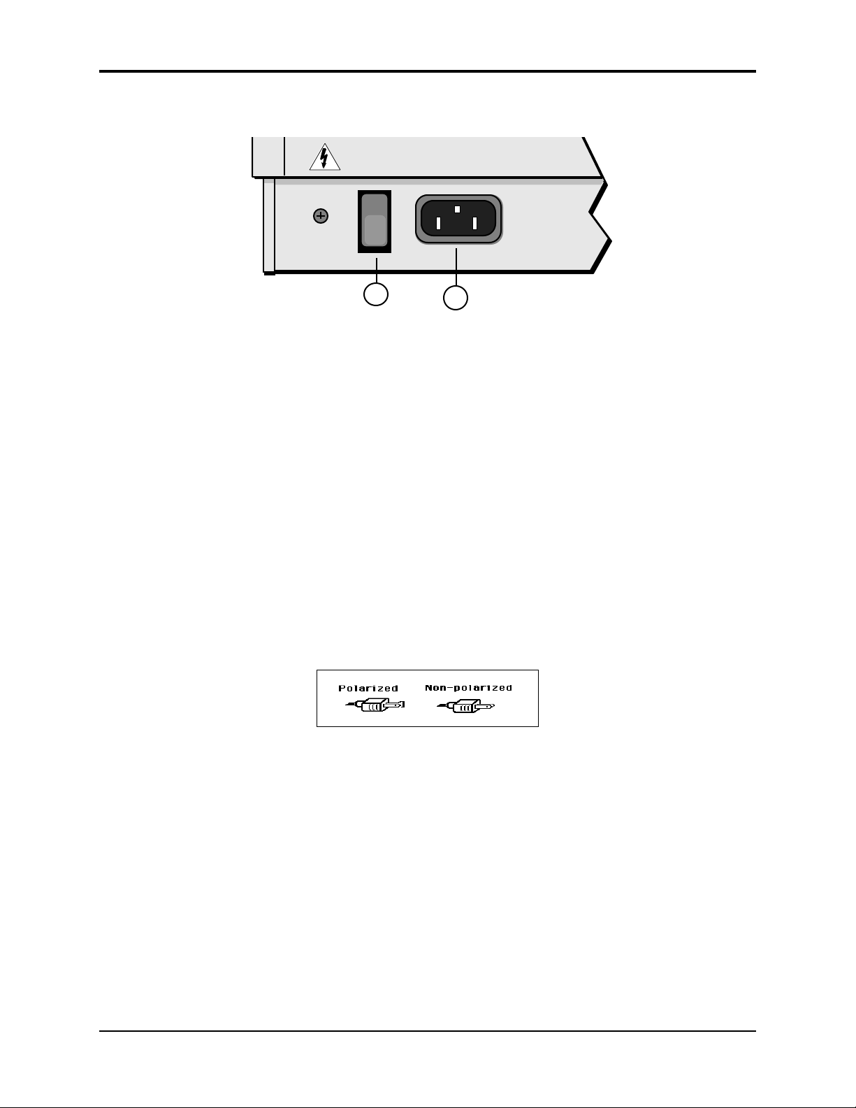
Power
1
Insert the line cord into the line receptacle on the back of the ASR-10 (2), next to the power switch
(1). Plug the other end of the cable into a grounded AC outlet. The proper voltage for your ASR10 is listed on the Serial Number label on the rear panel. Turn the ASR-10 power on and make
sure the display lights up. If not, check your connections and power source.
Power — Polarization and Grounding
Like many modern electrical devices, your ASR-10 has a three-prong power cord with earth
ground to ensure safe operation. Some products have power cords with only two prongs and no
earth ground. To ensure safe operation, modern products with two-prong power cords have
polarized plugs that can only be inserted into an outlet the proper way. Some products, such as
older guitar amplifiers, do not have polarized plugs and can be connected to an outlet incorrectly.
This may result in dangerous high voltages on the audio connections that could cause you
physical harm or damage any properly grounded equipment to which they are connected, such
as your ENSONIQ product.
To avoid shock hazards or equipment damage, we recommend the following precautions:
• If you own equipment with two pronged power cords, check to see if they are polarized or
non-polarized. You might consider having an Authorized Repair Station change any nonpolarized plugs on your equipment to polarized plugs to avoid future problems.
2
• Exercise caution when using extension cords or plug adapters. Proper polarization should
always be maintained from the outlet to the plug. The use of polarized extension cords and
adapters is the easiest way to maintain proper polarity.
• Whenever possible, connect all products with grounded power cords to the same outlet
ground. This will ensure a common ground level to prevent equipment damage and
minimize hum in the audio output.
AC outlet testers are available from many electronic supply and hardware stores. These can be
used to check for proper polarity of outlets and cords.
iv Disk Care
Page 5
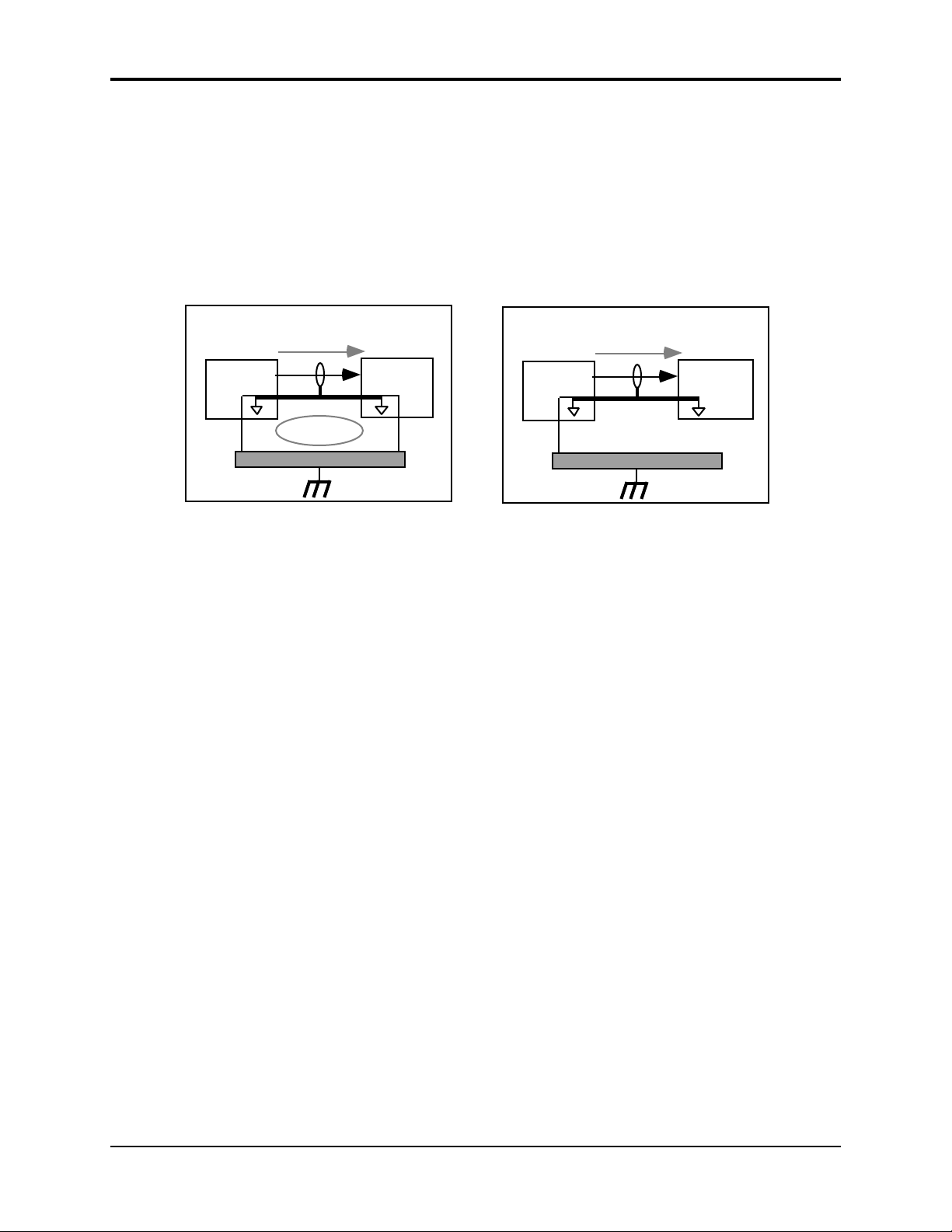
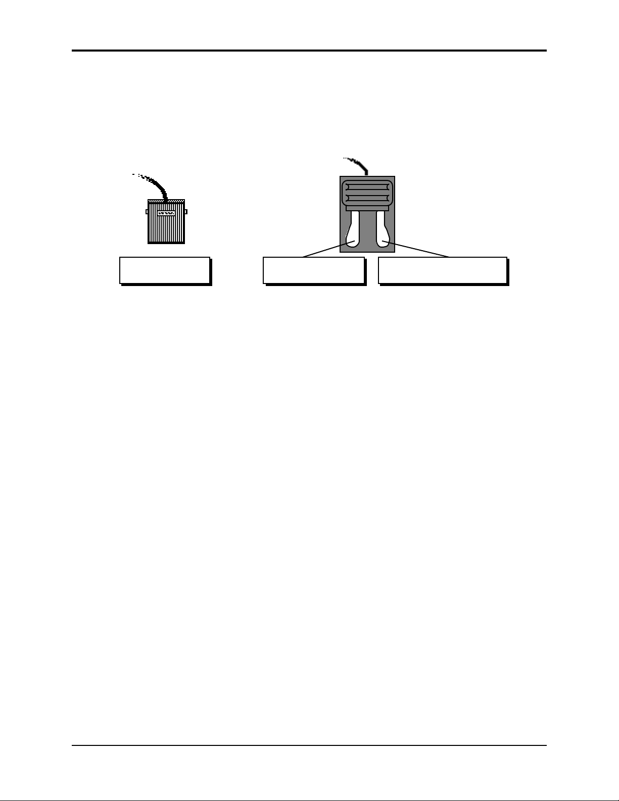
Ground Loops
Sometimes currents flowing through the ground line generate a signal seen by another part of the
circuit sharing the same ground. In other words, if there are two identical signal paths within a
circuit, they can form a loop which can result in hum and/or noise. If you are using equipment
that has 3-prong “grounded” AC power cords, you may suffer from a ground loop resulting from
the interconnection of this equipment. The following diagram shows how cascading or
“chaining” the output of one 3-prong grounded system into the input of another 3-prong
grounded system with a standard unbalanced 2 conductor cord (like a 1/4” guitar cable) can
result in a ground loop.
Preface
Unbalanced Output to Unbalanced Input.
Single conductor shielded cable
3-Prong
"Grounded"
System
SIGNAL PATH
+
(circuit ground)
Earth Ground
Fig. 1 depicts a system interconnection where a ground loop can exist. Fig. 2 depicts a system
interconnection where a ground loop does NOT exist. When interconnecting 3-prong grounded
systems, you can use signal isolation transformers to prevent ground loops. This coupling
transformer effectively isolates two interconnected system signal grounds, while still allowing
the signal to pass through.
AC Line Conditioning
As is the case with any computer device, the ASR-10 is sensitive to sharp peaks and drops in the
AC line voltage. Lightning strikes, power drops or sudden and erratic surges in the AC line
voltage can scramble the internal memory and, in some cases, damage the unit’s hardware. Here
are a few suggestions to help guard against such occurrences:
>
Ground Loop
<
FIG. 1
3-Prong
"Grounded"
+
System
Unbalanced Output to Unbalanced Input.
Single conductor shielded cable
3-Prong
"Grounded"
System
SIGNAL PATH
+
(circuit ground)
Earth Ground
2-Prong
"UNGrounded"
+
System
FIG. 2
• A Surge/Spike Suppressor. The cheaper of the options, a surge/spike suppressor absorbs
surges and protects your gear from all but the most severe over-voltage conditions. You can
get multi-outlet power strips with built-in surge/spike suppressors for little more than the
cost of unprotected power strips, so using one is a good investment for all your electronic
equipment.
• A Line Conditioner. This is the best, but by far the more expensive, way to protect your gear.
In addition to protecting against surges and spikes, a line conditioner guards the equipment
against excessively high or low line voltages. If you use the ASR-10 in lots of different
locations with varying or unknown AC line conditions, you might consider investing in a line
conditioner.
Disk Care v
Page 6
Preface ASR-10 Musician’s Manual
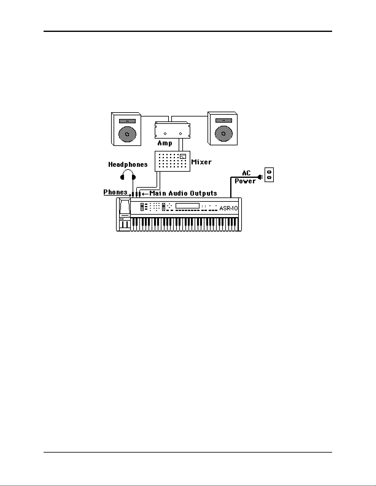
Amplification
Connect the Main Audio Outputs of the ASR-10 to the line level inputs of a mixer, instrument
amplifier, stereo, or any other sound system, using 1/4 inch audio cables. If your system is
stereo, connect the Left and Right Main Outputs to two channels of your mixer, stereo, etc. If it’s
mono, use either of the Main Audio Outputs, but make sure nothing is plugged into the other
output. For listening through headphones, plug the phones into the rear panel jack marked
Phones. If you’re running the ASR-10 through a mixer, in stereo, be sure to pan the left input
channel on the mixer fully left, and the right input channel fully right.
It is a good idea to make sure your audio system is turned off (or down) when making
connections, to avoid damaging speakers or other components.
Note: The ASR-10 outputs are line-level, and are intended to be connected only to line-level inputs,
such as those on a mixer, stereo pre-amp, keyboard amp, etc. Connecting the ASR-10 audio
outputs to a mic-level input, such as a guitar amp or the microphone jacks on a tape deck, is not
recommended, and might result in damage to the device input.
Move the Volume Slider all the way up. As with any digital musical instrument, the ASR-10 will
give the best results if you keep the Volume Slider full on, and use the volume control on your
mixer or amp to adjust its level.
Switch the audio system on, and adjust the amplifier volume for normal listening levels. If you
hear no sound while playing the keyboard, switch the audio system off and check your
connections.
Running Your ASR-10 Through a Home Stereo System
If you are thinking about amplifying your ASR-10 through your home stereo, a word of caution is
in order. A home stereo is great for playing CD’s, albums, tapes — the dynamic range of these
media is limited, and your speakers aren’t usually subjected to extreme volume changes and
frequency transients. While the dynamic range of CD’s is significantly greater than LP’s or tapes,
the output of a CD player is still conservative compared to the uncompressed, unlimited linelevel output of a pro-level keyboard. Running your ASR-10 — or any pro-level keyboard
through a home stereo at high volume levels can damage your speakers, not to mention the
impedance mis-match this can create. If your only means of amplification is your home stereo,
then try to keep your levels on the conservative side.
vi Disk Care
Page 7
Care and Feeding of the Disk Drive
The ASR-10’s built-in disk drive is used to store all your Instruments, Banks, and Sequencer data,
as well as System Exclusive messages from other MIDI devices. The ASR-10 uses a Quad-density
disk drive that can store 1600 Kilobytes of data on a Double-Sided High-Density (DSHD) 3.5”
micro-floppy disk and 800 Kilobytes of data on a Double-Sided Double-Density (DSDD) 3.5”
micro-floppy disk. The disks are enclosed in a protective plastic carrier with an automatic shutter
to protect the diskette from physical damage. It is important not to alter this carrier in any way.
Preface
Do’s:
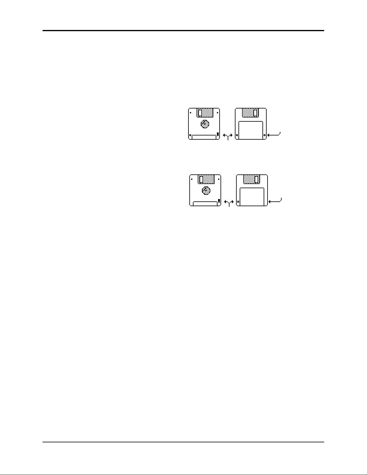
The 3.5” disks have a sliding writeprotection tab so that you can protect
your sounds and sequences against
accidental erasure. Sliding the writeprotection tab in the lower left corner of
the disk so that the window is closed
will allow you to store information on
the disk. Sliding the tab so that the
window is open will protect the disk
against being accidentally reformatted
or having files deleted. Double-Sided
High Density disks can be easily
identified because they have an
additional window (with no writeprotection tab) located on the lower
right corner of the disk.
Floppy disks are a magnetic storage medium, and should be treated with the same care you’d
give important audio tapes. Just as you would use high quality audio tapes for your important
recording needs, we recommend using high quality floppy disks for your ASR-10. Here are a few
Do’s and Don’t’s concerning disks and the disk drive.
• Use either Double-Sided High-Density (DSHD) or Double-Sided Double-Density (DSDD) 3.5
inch Micro-floppy disks. Both types are available from almost any computer store and many
music stores carry them as well.
• Keep your disks and the disk drive clean and free of dust, dirt, liquids, etc.
• Label your disks and keep a record of what is saved on each.
• Only transport your unit with nothing in the drive.
Double-Sided High-Density (DSHD)
Disk
Window
Write Protect Tab
Double-Sided Double-Density (DSDD)
No Disk
Window
Write Protect Tab
Don’t’s:
• Don’t use Single-Sided (SSDD or SSSD) disks. These disks have not passed testing on both
sides. While a single-sided disk might work successfully with the ASR-10, it is possible that
you will eventually lose important data to a disk error if you try using Single-Sided disks.
• Don’t put anything other than a disk or the plastic sheet in the disk drive.
• Don’t transport the unit with a disk in the drive.
• Don’t expose disks to extremes of temperature. Temperatures below 50˚ F and above 140˚ F
can damage the plastic outer shell.
• Don’t expose your disks to moisture.
• Don’t dry your disks in a microwave oven.
• Don’t subject disks to strong magnetic fields. Exposure to magnetic energy can permanently
damage the information on the disk. Keep disks away from speaker cabinets, tape decks,
power cables, airline x-ray equipment, power amplifiers, TV sets, and any other sources of
magnetic energy.
• Don’t eject the disk while the drive is operating (i.e. when the disk drive light is on).
Disk Care vii
Page 8

Preface ASR-10 Musician’s Manual
Backing-up the O.S. Disk
Since floppy disks are vulnerable to the affects of magnetic fields, we highly recommend making
back-up copies of your O.S. disk. Doing so can save time and frustration in the unlikely event
that the O.S. disk becomes damaged. Since the tutorial files and the additional 44.1 kHz effect
algorithms are on the O.S. disk, you will need a HD (high density) disk to save all of the
information. We’ll use the COPY FLOPPY DISK command to back up the disk. Here’s how:
1. Slide open the plastic write-protect tab on the original O.S. disk (you should be able to see
through the little square hole) so that the disk is write-protected (protected from being written
to). This is an extra precaution to safeguard the data.
2. Press Command, then System•MIDI, and scroll to the COPY FLOPPY DISK command.
3. Press Enter•Yes.
The display shows INSERT SOURCE DISK (the one you want to copy).
4. Insert the source disk, then press Enter•Yes.
The drive will engage and the display will flash READING SOURCE DISK. Once the drive
stops, the display will change to show INSERT DEST DISK.
5. Insert the destination disk (the one you want to copy to) and press Enter•Yes.
If the destination disk is unformatted, the display will ask ERASE AND FORMAT DISK?
Press Enter•Yes to format the disk. When formatting is complete, the drive will engage and
the display will flash WRITING DEST DISK.
After writing to the destination disk, the display will read VERIFYING DEST DISK. If the
copy is complete, the display will read DISK COMMAND COMPLETED.
If you do not want to copy all of the tutorial files or the 44.1 kHz effect algorithms, use the
Command/System•MIDI, COPY O.S. TO DISK command (as described in Section 2 —
System•MIDI).
We recommend that you use the copied O.S. disk for daily use, and store the original O.S. disk in
a safe place. If your O.S. disk becomes damaged and you do not have a back-up copy made, your
local Authorized ENSONIQ Dealer can make a new copy for you (you must supply the disk).
viii Backing-Up the O.S. Disk
Page 9

Accessories
These optional accessories are available from your Authorized ENSONIQ Dealer:
• OEX-6sr Output Expander — The OEX-6sr gives the ASR-10 six additional outputs, grouped
in three stereo pairs in addition to the built-in stereo outputs. Each WaveSample, or an entire
instrument/track can be assigned to any of the stereo pairs and panned within the stereo field.
• SP-3 SCSI Kit — This SCSI (Small Computer Serial Interface) allows the ASR-10 to
communicate with a hard drive, CD ROM player, or computer. Hard drives provide a faster,
more convenient way to store instrument, sequencer, bank, and MIDI files. The SP-3 must be
installed by an Authorized ENSONIQ Repair Station.
• DI-10 Digital I/O Board (S/PDIF) — Allowing digital input and output using RCA-type
connectors. The DI-10 must be installed by an Authorized ENSONIQ Repair Station.
• Model CVP-1 CV PEDAL — A Control Voltage Foot Pedal which can be assigned as a
modulator within the voice section of the ASR-10 or used as a volume pedal.
• ENSONIQ Model SW-10 Dual Foot Switch — Can be used for hands-free patch select control
(when plugged into the Patch Select jack) or used for modulation control, voice sustain, or
starting, stopping, and continuing the internal sequencer (when plugged into the Foot Switch
jack).
• ENSONIQ Model SW-6 Foot Switch — A single damper piano style foot switch, for sustain,
or to function as the right patch select button.
• CDR Series — These CD ROMs offer a vast array of instruments, banks, and sequence/song
arranged in directories by file types. The CDR Series also features Direct Macros, which
allows instant access (direct-dial) to any instrument file.
• AS –Series Sound Libraries — The AS sound libraries are designed exclusively for the ASR10, provided on five High Density disks.
• SL, SLT, and ESS Sound Libraries — The ASR-10 can read all of the disks designed for the
EPS Series. These disks offer the largest, most accurate, responsive, and musical sampled
sounds available anywhere. These sounds are divided into three separate libraries: SL, a
series of five-disk sets featuring sounds specifically designed for the EPS-16 PLUS, but fully
compatible with the ASR-10; SLT, a series of ten-disk packs originally designed by top sound
programmers for the EPS, also compatible with the ASR-10; and ESS, three-disk “Signature
Series” sets designed by renowned industry performers and producers like Joey DeFrancesco,
Jason Miles, Maurice White, The System, Nile Rodgers, David Hentschel, and others.
Preface
An Important Note About Non-ENSONIQ Accessories and Your ENSONIQ
Warranty
ENSONIQ highly recommends that users who wish to add SCSI or a Digital I/O Interface to their
ASR-10 use ENSONIQ-made accessories. However, for those who wish to purchase a nonENSONIQ product, there are some important things to know about non-ENSONIQ products and
your ASR-10’s warranty:
• ENSONIQ
ASR-10.
• If your ASR-10 requires servicing, and a non-ENSONIQ accessory is installed, ASR-10 owners
will pay a service fee to have it removed so that a technician can diagnose the base unit.
• If it is determined that the use of an unapproved Non-ENSONIQ product caused damage,
then the repair of that damage is not covered by the ENSONIQ warranty. Any nonENSONIQ product which requires opening the case must be installed by an Authorized
ENSONIQ Repair Station.
• In addition, if it is found that continued use of a non-ENSONIQ product causes damage to
your ASR-10, any future service that your unit might require may not be covered under the
ENSONIQ warranty.
will not
approve any Non-ENSONIQ SCSI kits or Digital I/O Interfaces for the
An Important Note ix
Page 10

Preface ASR-10 Musician’s Manual
Need More Help?
Whether you’re an aspiring programmer looking for additional information about basic sampling
techniques and MIDI theory, or a professional sound designer working with advanced
applications, you may want more detailed information that is beyond the scope of this manual.
The following books can help enhance your understanding of sampling, synthesis, MIDI, and
related topics. These, in addition to the numerous monthly magazines, provide a wealth of
information. While we don’t endorse any one of these publications, we offer this partial list as a
resource for you to draw on.
The Mix Bookshelf
For prices and more information call: 1-800-233-9604
MIDI
MIDI FOR MUSICIANS, Craig Anderton
THE MIDI MANUAL, David Huber
THE MIDI HOME STUDIO, Howard Massey
THE NEXT MIDI BOOK, Rychner & Walker
THE MIDI BOOK, Steve De Furia, Joe Scacciaferro
THE MIDI RESOURCE BOOK, Steve De Furia, Joe Scacciaferro
HOW MIDI WORKS, Dan Walker
MIDI SYSTEMS & CONTROL, Francis Rumsey
USING MIDI, Helen Casabona, David Frederick
MIDI, THE INS, OUTS AND THRUS, Jeff Rona
SAMPLING
THE SAMPLING BOOK, Steve De Furia, Joe Scacciaferro
SAMPLING BASICS, Bobby Maestas
SYNTHESIZERS
GUITAR SYNTH & MIDI, Guitar Player Magazine
SECRETS OF ANALOG AND DIGITAL SYNTHESIS, Steve De Furia
SYNTHESIZER PERFORMANCE & REAL TIME TECHNIQUES, Jeff Pressing
SYNTHESIZER BASICS, Dean Friedman
MUSIC & TECHNOLOGY, H.P. Newquist
A SYNTHESIST'S GUIDE TO ACOUSTIC INSTRUMENTS, Howard Massey
Alfred Publishing Company
For prices and more information call 1-818-891-5999
MIDI
ADVANCED MIDI APPLICATIONS, GPI
BASIC MIDI APPLICATIONS, GPI
WHAT IS MIDI?, GPI
SYNTHESIZERS
BEGINNING SYNTHESIZER, GPI
PLAYING SYNTHESIZERS, GPI
SYNTHESIZER PROGRAMMING, GPI
Hal Leonard Publishing
For prices and more information call 1-414-774-3630
MIND OVER MIDI, GPI
SYNTHESIZER TECHNIQUE (REVISED), GPI
x
Page 11

Monthly Magazines
The following magazines offer many specific articles and columns that can provide a plethora of
useful information.
THE TRANSONIQ HACKER
For prices and more information about this independent news magazine for ENSONIQ
Users, call 1-503-227-6848
KEYBOARD
For subscription rates and more information call 1-800-289-9919
ELECTRONIC MUSICIAN
For subscription rates and more information call 1-800-888-5139
HOME & STUDIO RECORDING
For subscription rates and more information call 1-818-407-0744
MIX
For subscription rates and more information call 1-800-888-5139
EQ
For subscription rates and more information call 1-212-213-3444
Preface
xi
Page 12
Section 1 — Controls & Architecture
This section provides an introduction to the ASR-10’s many controls and rear panel connections,
a conceptual overview of the system, a guide to understanding memory, and a discussion of
editing various types of parameters. We suggest you read this section carefully — it will help
you get the most out of your ASR-10.
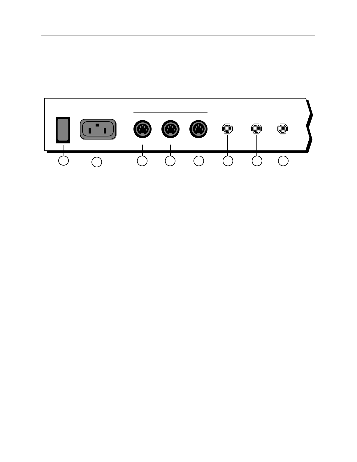
Rear Panel Connections
MIDI
Thru OutIn
Patch Select
Foot Switch
Pedal•CV
1 3
1) Power
The power switch turns the ASR-10 on and off. When you turn the power on, the display lights
up and shows “PLEASE INSERT DISK,” which is the prompt to load the operating system.
2) AC Line In
The supplied line cord connects here. The correct voltage for the ASR-10 is on the rear panel
along with the serial number. If you travel, remember the ASR-10 will only operate on the listed
voltage.
3) MIDI Thru
This jack “passes on” all MIDI (Musical Instrument Digital Interface) information received by the
ASR-10 to other MIDI devices. Information generated by the ASR-10 itself does not go to this jack
— the Thru jack merely echoes what comes into the MIDI In jack.
4) MIDI In
This jack receives MIDI information from other MIDI instruments or computers.
5) MIDI Out
This jack transmits MIDI information generated by the ASR-10 keyboard and/or sequencer to
other instruments and computers.
6) Patch Select (Foot Switch)
If you connect the optional SW-10 Dual Foot Switch in this jack, it duplicates the function of the
Patch Select buttons, allowing hands-free patch select changes. This jack requires a dual foot
switch and will not work properly with a single foot switch (SW-2 or SW-6).
2
4
5
6 8
7
7) Foot Switch
This jack supports either one or two foot switches depending on what is plugged into it:
• If you plug the ENSONIQ Model SW-2 Foot Switch (which came with your ASR-10) into this
jack, it will act as a Sustain pedal. Holding it down will cause notes to continue to sustain
after the key has been released.
• Or you can connect the optional ENSONIQ Model SW-10 Dual Foot Switch here. The SW-10 is
a dual (piano-type) foot switch with two separate pedals. When the SW-10 is connected, the
Right Foot Switch will act as a sustain pedal and the Left Foot Switch is assignable.
1
Page 13
Section 1 — Controls and Architecture ASR-10 Musician’s Manual
Note: If you are using a single foot switch (SW-2 or SW-6), the Edit/System•MIDI, LEFT FOOT SW
parameter should be set to OFF. This will prevent unexpected behaviour. Remember that the
Foot Switch jack is optimized for use with a dual foot switch (SW-10), and when a single foot
switch is connected, it behaves like the Right Foot Switch.
When the SW-2 is connected
to the Foot Switch jack:
It acts as the
Sustain Pedal.
A parameter on the Edit/System•MIDI page (press Edit, then System•MIDI, then scroll until
the display reads “LEFT FOOT SW=OFF”) determines the function of the Left Foot Switch.
Tip: The Sustain pedal can be used to dynamically “latch” the current amount of pressure being
exerted on the keyboard. Here’s how:
1) Select a sound that responds to pressure. Choose a sustaining sound like an organ.
2) Play a key and press into the keyboard until you can hear the pressure modulation
affect the sound of the note.
3) Press and hold the Sustain pedal.
4) Release the key. You will hear that the sound continues to be modulated by pressure
at the depth to which you were pressing.
5) Play a different key. Notice that the new note is not modulated. You can now press
into the keyboard and modulate the new note independent of the note that is
sustained. When the current pressure output exceeds the latched level, pressure on
the new note will modulate both notes.
6) To release the “latched” pressure value on the sustained note, either press the
“latched” key again, or release the Sustain pedal.
When the SW-10 is connected to
the Foot Switch jack:
The Left Foot Switch
is assignable.
The Right Foot Switch acts
as the Sustain Pedal.
2 Rear Panel Connections
Page 14

8) Pedal•CV
This jack is for connecting an optional ENSONIQ Model CVP-1 Control Voltage Foot Pedal,
which is assignable as a modulator to various parameters within the ASR-10. The pedal gives
you a handy alternative modulation source when, for example, you would want to use the Mod
Wheel but both hands are busy.
Section 1 — Controls and Architecture
ENSONIQ
CVP-1
Control Voltage Foot Pedal
A CV pedal plugged into this jack can also act as a Volume pedal, controlling the volume of the
currently selected Instrument•Sequence Track(s). A parameter on the Edit/System•MIDI page
(press Edit, then System•MIDI, then scroll until the display reads PEDAL=VOLUME MIDI=7),
determines whether the CV pedal will act as a modulator or as a volume pedal. Set to
PEDAL=VOLUME to use the CV pedal to control volume.
Pedal/CV Specs: 3-conductor (Tip= control voltage input, Ring=510 ohm resistor to +5 Volts,
Sleeve= ground). 36 KOhm input impedance, DC coupled. Input voltage range=0 to 3 volts DC.
Scan rate=32mS (maximum recommended modulation input= 15 Hz). For use with an external
control voltage, use a 2-conductor cable with the voltage on the tip and the sleeve grounded.
Rear Panel Connections 3
Page 15
Section 1 — Controls and Architecture ASR-10 Musician’s Manual
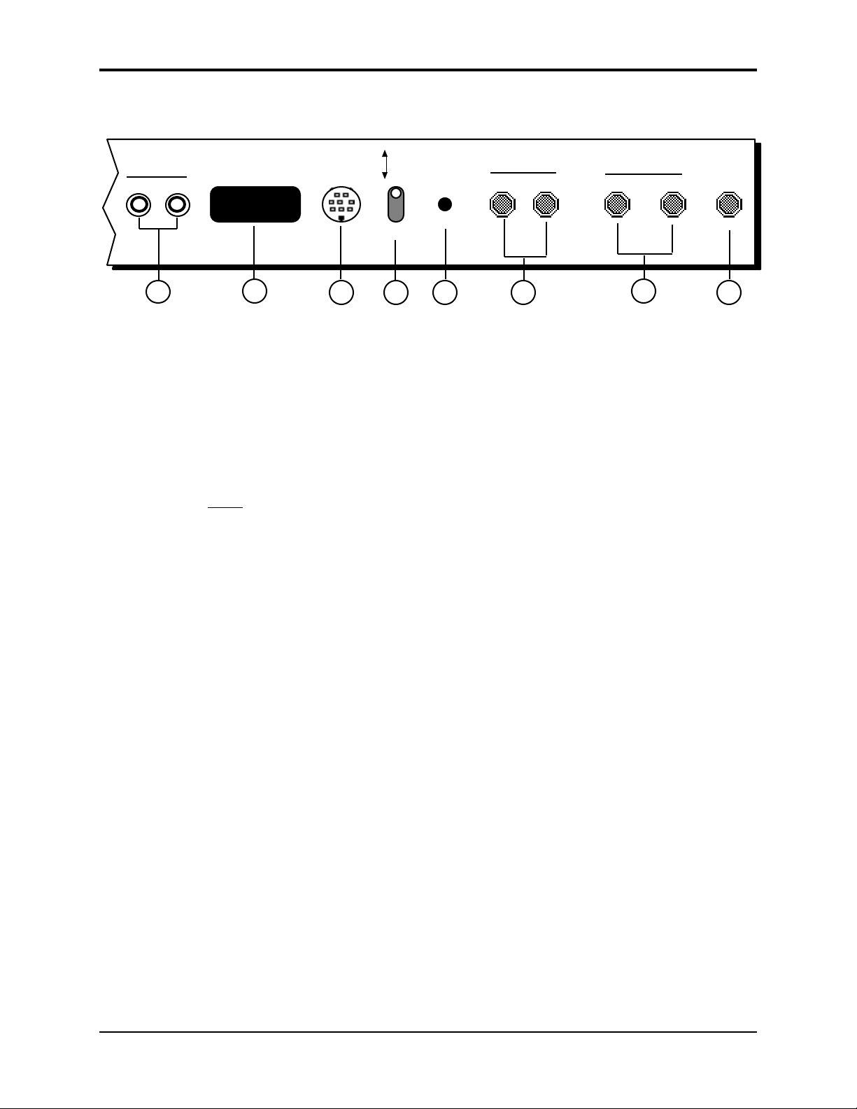
Rear Panel Connections Cont’d.
Digital I/O
In
Out
SCSI
10
Output
Expander
11 1312
Mic
Line
Input
Level
Audio Input
B/Right
14
A/Left
Main Out
Left/MonoRight/Mono
15
9) Digital I/O — Input/Output
The DI-10 Digital I/O Interface (S/PDIF) provides direct Digital Input and Output connection to
and from the ASR-10 using RCA-type connectors. The Digital Output will provide direct 44.1
kHz digital audio output of the Main Output mix when the current effect uses a 44.1 kHz sample
rate. The Digital Input can be used for direct digital sampling from an external digital audio
source at 44.1 or 48 kHz.
The Digital Input and Output conforms to the S/PDIF standard.
Note: If you wish to record the 44.1 kHz digital output of the ASR-10 to a DAT recorder, the DAT
recorder
must be able to record from its digital input at 44.1 kHz. Some older/consumer DAT
recorders do not record at 44.1 kHz as a copy protection scheme: these DAT recorders will not
record the ASR-10’s 44.1 kHz digital output.
Phones
169
10) SCSI Interface
This space is for the optional SP-3 SCSI kit that allows the ASR-10 to transfer data to and from a
SCSI-compatible hard disk, CD ROM player, or exchange information with computers at very
high speed.
11) Output Expander (AUX 1, 2, 3)
This multi-pin connector is used to connect the optional OEX-6sr Output Expander box, which
provides the ASR-10 with three pairs of stereo outputs (or 6 individual outs) in addition to the
built-in stereo outputs. Each WaveSample, or an entire Instrument•Sequence Track, can be
assigned to any of the three AUX stereo pairs and can be independently panned within the stereo
field.
12) Mic/Line Switch
This switch is used to change between either a mic (up) or a line (down) level input source.
13) Input Level Trim Control
This knob allows you to amplify the level of the external signal source.
4 Rear Panel Connections
Page 16

14) Audio Input — B/Right and A/Left
These jacks are the Right and Left Audio Inputs into the ASR-10 for sampling or Audio Track
monitoring of external analog audio sources.
SPECS: 140 KOhm input impedance, AC coupled. The Audio Inputs have 2 ranges: Line and
Mic. With the Mic/Line switch set to Line, the
ASR-10 will accommodate signals from +15.5dBV (Input Level Trim control fully
counterclockwise) to -16.5dBV (Input Level Trim control fully clockwise). With the Mic/Line
switch set to Mic, the ASR-10 will accommodate signals from -11.5dBV (Input Level Trim control
fully counterclockwise) to -43.5dBV (Input Level Trim control fully clockwise). Matching the
appropriate input level with the correct settings of the Mic/Line switch and Input Level Trim
control will bring the external signal source up to clipping level.
15) Main Out — Right/Mono and Left/Mono
To operate the ASR-10 in stereo, connect these outputs to two discrete channels of your mixer
and pan the mixer channels right and left. Note that either of the audio outputs can be used as a
mono output. If you want to listen to the output in mono, make sure that only one of the output
jacks is connected.
16) Phones
To listen to the ASR-10 in stereo through headphones, plug the phones into this jack. The phones
output contains a mix of the signal from the main outputs. Headphone volume is controlled by
the volume slider on the front panel. Note that plugging headphones into this jack does not
automatically turn off the audio in the right and left outputs.
Section 1 — Controls and Architecture
Rear Panel Connections 5
Page 17
Section 1 — Controls and Architecture ASR-10 Musician’s Manual
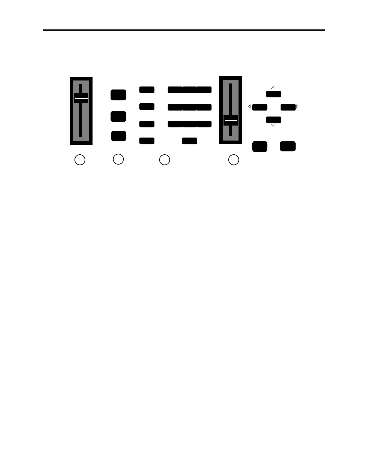
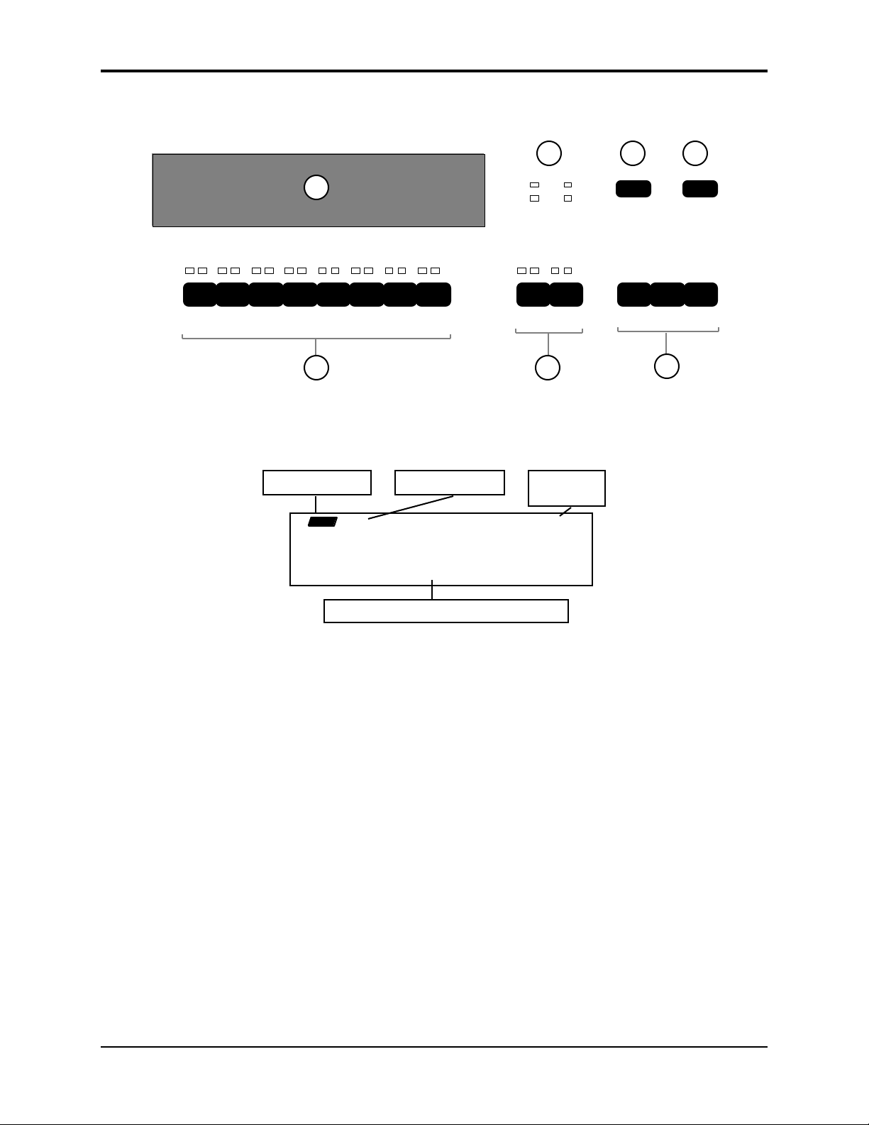
Front Panel Controls
Almost everything you do on the ASR-10 — whether it’s selecting a sound, editing that sound,
adjusting the tuning, etc. — is controlled from the front panel using the following controls:
Volume Data Entry
1
1) Volume Slider
This controls the overall volume of the ASR-10 audio outputs.
2) Mode Buttons
These three buttons are the key to finding your way around the ASR-10. The ASR-10 is always in
one of these three Modes — LOAD, COMMAND, or EDIT. The current mode is selected by
pressing the appropriate mode button. The highlighted word in the upper left corner of the
display tells you which is the current mode.
• LOAD mode is the one you will be in most often — since the ASR-10 lets you continue playing
while loading sounds and sequences, LOAD mode also doubles as the “Performance” mode.
When the LOAD indicator is flashing, the display is showing you disk files for loading. When
the LOAD indicator is lit but not flashing, the display is showing you the name(s) of the
instruments in the Internal Memory.
Load
(Select Preset)
Command
(Create Preset)
Edit
2
Instrument
Seq•Song
System•MIDI
(Directory)
Effects
Env 1
Env 2
Env 3
192
Pitch
4
LFO
7
Filters
Amp
5
Wave Layer
8
Track
0
3
6
3 4
EnterCancel
YesNo
Tip: In flashing LOAD mode (when the LOAD indicator is flashing), successive presses of the
Instrument, Seq•Song, System•MIDI, or Effects buttons will scroll through the available files
of that type on the selected storage device.
• COMMAND mode is used to execute a wide variety of commands, such as: saving
instruments, banks, and sequences to disk; copying instruments, layers, and WaveSamples
from one internal location to another; creating and modifying sequences and songs; and
manipulating WaveSamples and their loops in various ways... just to name a few.
Tip: In COMMAND mode, successive presses of each of the 14 page buttons will scroll through the
Command screens, one at a time.
• EDIT mode is used to select and modify a great many variables — or parameters — ranging
from the volume of a WaveSample, to the velocity response of the instrument, to the MIDI In
Mode. Edit mode is also the mode in which all sequence recording and mixing is done.
Tip: In EDIT mode, successive presses of each of the 14 page buttons will scroll through the Edit
screens, one at a time.
6 Front Panel Controls
Page 18

3) Page Buttons
Within each mode, the available disk files, commands, and parameters are organized into Pages.
A page is selected by pressing one of these fourteen page buttons. Once you are on the correct
page, you use the Data Entry Controls to scroll through the files, commands or parameters on
the page. A given page will have different functions depending on the current mode. Each mode
has a different set of pages available. Not all fourteen page buttons are active in all three modes.
The ten numbered page buttons also double as a numeric keypad for “direct-dialing” a given disk
file, command, or parameter or for sending MIDI Program Changes.
4) Data Entry Controls
Once you are in the desired mode and have selected the proper page, you use the controls in the
data entry section to: locate and load the desired file (in Load mode); locate and execute the
desired command (in Command mode); or locate and modify the value of the desired parameter
(in Edit mode).
• The Data Entry Slider and the Up and Down Arrow buttons will: move through the files on
the current disk or directory (in flashing LOAD mode); change the value of the current
parameter (in Edit mode); or respond when the ASR-10 asks you for further input during the
execution of a command (in Command mode).
• The Left and Right Arrow buttons are used primarily to move to the next parameter or
command on the current page.
Section 1 — Controls and Architecture
Tip: To advance by screens (instead of by parameters), while holding down the Right Arrow button,
press the Up Arrow button, or while holding down the Left Arrow button, press the Down
Arrow button.
• The Enter•Yes and Cancel•No buttons are used to either proceed with or cancel the function
currently showing on the display.
Tip: When editing any parameter, pressing Cancel•No will reset the parameter to the value it was set
to before it was last edited.
Tip: In Load mode, successive presses of the Cancel•No button will alternate between solid and
flashing Load modes.
Tip: When editing any parameter that has a center value, there is an easy way to reach that value.
While holding down the Down Arrow button, press the Up Arrow button, then quickly release
both buttons.
Parametric Programming
The method used to modify or edit programs, presets and system parameters is called Pagedriven Parametric Programming, which sounds like a mouthful, but don’t worry. Once you’ve
grasped a few basic concepts you’ll find that operating the ASR-10 is quite simple, given its many
capabilities.
It is likely that you have already encountered some form of parametric programming on other
synthesizers or samplers. What this means is that instead of having a separate knob or slider for
each function, you have one master Data Entry Slider and the Up/Down and Left/Right Arrow
buttons, which adjust the value of whichever parameter you select.
This approach has many advantages, the most obvious is that it greatly reduces the amount of
hardware — knobs, switches, faders, etc. needed to control a wide variety of functions. If the
ASR-10 had a separate control for each function, it would literally have hundreds of knobs.
Front Panel Controls 7
Page 19
Section 1 — Controls and Architecture ASR-10 Musician’s Manual
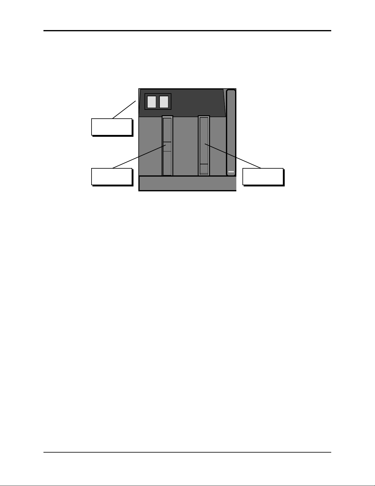
Additional Front Panel Controls
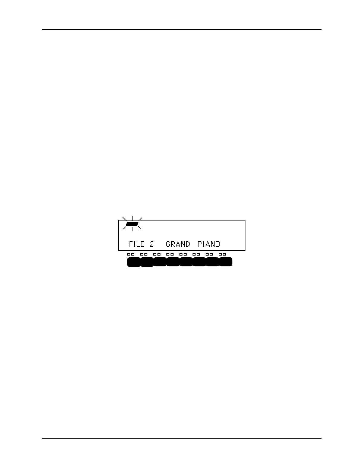
5) Display
The ASR-10 Display is divided into two main sections: the Indicator Lights in the top half of the
window and the 22-character Alphanumeric Display at the bottom of the window.
StopRecord
Continue
11
87
FX Select
FX Bypass
Play
6
Left Right
5
1
32
Instruments
Sequence Tracks
8
7
6
5
4
9
Mode Indicator Page Indicator
Peak
Signal
Input Level
A
B
Audio Tracks
10
Sequencer
Sample
Source Select
Status
LOAD INST STOP
The indicator lights will tell you which mode the ASR-10 is in (Load, Command, or Edit); which
page it is on; and the sequencer status (Stop, Play, Record, etc.). The 22-character alphanumeric
display is used to show you information about specific files, commands, parameters, etc. It will
also ask you for additional input when necessary, such as which track you want to load an
instrument into, or which WaveSample you want to edit.
6) Input Level LED Meters
These 2 dedicated Input Level meters provide separate Left/Right metering of the Audio Input
levels, pre-FX, at all times. The green Signal LEDs light at -24 dB. The red Peak LEDs light at 6
dB below clipping.
7) Sample•Source Select Button
This button is used to initiate sampling (digitally recording sounds) by the ASR-10. The Record
Source selected on this page will determine the audio signal that will be monitored on the Audio
Tracks.
FILE 2 GRAND PIANO
22-character Alphanumeric Display
8 Front Panel Controls
Page 20

8) FX Select•FX Bypass Button
This button acts as the “master” control switch for the built-in effects, determining which, if any
effect will be used and how it will interact with the instruments that reside in the internal
memory. The controls on this page also determine the current sample rate and polyphony.
9) Instrument•Sequence Track Buttons — 1 through 8
These eight buttons are used to select, deselect, and “stack” the various instruments that are
loaded into the internal memory of the ASR-10. For each of the eight locations, the two LEDs
above the button indicate whether an instrument is Loaded into that location (red LED lit) and
whether it is Selected (yellow LED lit). See “Playing Instruments” later in this section for a full
discussion of the Instrument•Sequence Track buttons.
Each instrument location is also a sequencer track — that is, whatever is recorded on track 1 of a
sequence will play the instrument that is loaded into location #1. When you are recording,
editing or mixing sequences and songs, you use these buttons to select the current track.
10) Audio Track Buttons — A and B
Audio Tracks are used to record RAMTracks and DiskTracks. The two Audio Track buttons
control audio monitoring of the stereo audio inputs through effects (if desired), enabling you to
monitor during sampling, sing along (or play a guitar) to sequencer playback, or record your
performance to the Audio Tracks. Each Audio Track has its own Edit/Track MIX, PAN, and
OUT bus assignment. The signal monitored on Audio Tracks is the signal that will be sampled or
recorded to the Audio Tracks.
Section 1 — Controls and Architecture
Each Audio Track button contains 2 LEDs:
• The left LED is red, and is labelled “Source Monitor.” When lit, it indicates that the Audio
Track Record Source (set on the Sample•Source Select page, REC SRC parameter) can be
monitored on the Audio Track, and that a voice is being used to monitor this audio signal.
When the Source Monitor LED is off, the Audio Track is muted and inaudible.
When REC SRC= MAIN-OUT, the audio inputs are disabled, and both Source Monitor LEDs
remain off at all times. This happens because REC SRC= MAIN-OUT recording is all ASR-10
generated audio that is routed to BUS1, 2, or 3, and the Source Monitor voices are not needed
to monitor this REC SRC, as it is always audible out the Main Outs.
• The right LED is yellow, and is labelled “SELECTED.” When lit, it indicates that the track is
selected for parameter editing and/or Audio Track Recording, and that the Audio Signal
Source being monitored on the track is selected for sampling. When the SELECTED LED is
off, the track’s Edit/(audio) Track parameters cannot be edited, and the Audio Signal Source
being monitored on the track will not be sampled and will not be recorded to Audio Tracks.
See Section 12 — Sequencer and Audio Track Concepts for more information on Audio Tracks.
11) Sequencer “Transport Controls”
These three buttons are used to control the ASR-10’s internal multi-track sequencer.
Front Panel Controls 9
Page 21
Section 1 — Controls and Architecture ASR-10 Musician’s Manual
Performance Controllers
The ASR-10 features a number of real-time performance controllers that can modify sounds as you
play for maximum expressiveness. Three of the most important controllers are located to the left
of the keyboard:
Patch Select
Buttons
Pitch Bend
Wheel
• PATCH SELECT BUTTONS — These two buttons are used to select alternate groups of voices
(called Layers) within a sound. The ASR-10 can be programmed so that the sound changes
(sometimes in subtle ways, sometimes radically) when you play notes with one or both Patch
Select buttons held down As you play instruments on the ASR-10, make sure you explore
what these buttons do to each sound.
• PITCH BEND WHEEL — This wheel bends the pitch of a note up or down. The wheel is
normally centered, where it has no effect on the pitch — moving the wheel up or down will
bend the note by the amount specified in the Bend Range parameters contained on the
Edit/System•MIDI page (for GLOBAL BEND RANGE) and on the Edit/Pitch page (for an
individual WaveSample’s BEND RANGE).
• MODULATION WHEEL — Perhaps the most common use of the Mod Wheel is to add
vibrato, but it can also be assigned as a modulator anywhere within the ASR-10 voice
architecture to alter the pitch, brightness, volume and a great many other aspects of the sound.
Modulation
Wheel
10 Performance Controllers
Page 22

Pressure (After-touch)
Another important controller is Pressure. Pressure (often called after-touch) is a modulator that
allows you to change the sound in various ways by pressing down harder on a key or keys after
the initial keystrike. The ASR-10 keyboard is capable of generating two types of pressure —
Channel Pressure and Poly-Key™ Pressure.
Like the mod wheel or foot pedal, pressure is a modulator and can be chosen wherever a
modulator is selected in the programming section (see Section 9 — WaveSample and Layer Concepts)
of the ASR-10. Pressure can be assigned to alter the pitch or volume of voices, filter cutoff
frequency, LFO rate or depth, pan location, etc.
There are two types of Pressure:
• Channel Pressure, also called Mono pressure, affects all notes that are playing when you exert
pressure on any of the keys. For example, if you play a three note chord, pressing down
harder on any of the three notes of the chord will modulate all three notes. This type of
pressure is the more common of the two types.
Most MIDI instruments that currently implement pressure send and receive only channel
pressure. If you are playing such an instrument from the ASR-10, you should set the ASR-10
to send channel pressure. (Note that some devices, including all ENSONIQ products, respond
to both types of pressure.)
Section 1 — Controls and Architecture
• Poly-Key™ Pressure, also referred to as polyphonic pressure, is a more sophisticated and
expressive type of pressure. Poly-Key pressure affects each key independently. For example,
if you play a three-note chord, pressing down harder on any of the three notes of the chord
will modulate only that note. The other two notes will remain unaffected.
Each Instrument•Sequence Track can be programmed to generate Poly-Key pressure,
channel pressure or none at all. If you wish to change the pressure type for a given track, you
can do so on the Edit/Instrument page.
Tip: Poly-Key pressure generates a tremendous amount of data and will consume sequencer memory
much faster than other types of events, such as notes and program changes. You should turn
pressure off when sequencing instruments which do not respond to pressure, such as piano and
drum sounds.
About Pressure 11
Page 23

Section 1 — Controls and Architecture ASR-10 Musician’s Manual
Architecture
“Booting” the ASR-10
Insert the power cord into the line receptacle on the back of the ASR-10, next to the power switch.
Plug the other end of the cable into a grounded AC outlet. The proper voltage for your ASR-10 is
listed on the Serial Number label on the rear panel. Turn the ASR-10 power on and make sure
the display lights up. If not, check your connections and power source.
The ASR-10 Operating System (O.S.) — the computer program that tells the hardware what to do
— is “disk based.” This means that each time you turn the ASR-10 on, the first disk you insert
must be one containing an ASR-10 Operating System (see the disk label). This is called “booting”
the machine. Insert the disk with the label facing up and the sliding metal door facing away from
you. The display will read LOADING SYSTEM while the O.S. is being loaded. You should
always use the latest (highest-numbered) Operating System. If the first disk you put in the drive
doesn’t contain the ASR-10 Operating System — the display will flash O.S. NOT ON DISK or
DISK NOT FORMATTED. Just remove that disk and insert a proper ASR-10 O.S. disk.
Note: We recommend that you use a copy of the original O.S. Disk for daily use, and store the original
O.S. Disk in a safe place. For more information, see the Preface.
Right after the ASR-10 is finished loading the Operating System, and before it puts itself into
LOAD mode, it will calibrate its keyboard. During calibration the software scans each key and
optimizes its velocity and pressure response. The display will briefly read TUNING KBD HANDS OFF. It is important that you don’t play or hold down any keys during this time (see
below).
Once it has “booted” the ASR-10 is ready to operate, but it won’t make any sound until you
LOAD an instrument into its internal memory and then select that instrument by pressing its
Instrument•Sequence Track button. These functions will be covered later in this section.
Keyboard Calibration
Each time you switch it on, the ASR-10 will go through a boot-up routine that includes
calibrating the keyboard — a process by which the ASR-10 software is able to scan the entire
keyboard and optimize the response of each key. This ensures that the keyboard is always fine
tuned for the best possible response. The calibration process only takes about three seconds.
Never play the keyboard while it’s calibrating:
After you turn on the ASR-10 and insert the Operating System in the drive, the display will show
LOADING SYSTEM, then TUNING KBD - HANDS OFF. You should not play the keyboard
while this message is on the display. After about three seconds, the display will automatically
switch to show the instrument files on the current disk and the ASR-10 is ready for use.
If you do play the keyboard while it’s calibrating:
Playing keys during calibration will cause the display to show KBD FAILED - RETRY? Press
Enter•Yes to allow it to calibrate again, taking care not to play keys this time. In short, you
should make it a point not to play keys during the first few moments after turning the unit on.
If the KBD FAILED message appears without touching the keys:
If the display repeatedly shows KBD FAILED RETRY? even when you are not touching keys
during calibration, this would indicate a hardware problem and the unit should be serviced by an
Authorized ENSONIQ Repair Station.
Using the ASR-10 as a sound module only, after getting repeated KBD FAILED messages:
If you want to use the unit as a sound module after the display shows repeated KBD FAILED
RETRY? messages, press Cancel•No. This will disable the Poly-Key™ keyboard completely, but
the ASR-10 will respond normally to all button presses and incoming MIDI information from
another MIDI instrument.
12 Architecture
Page 24
Memory
Disk Memory vs. Internal Memory
The instruments, banks, and sequences that the ASR-10 plays are stored on 3.5” micro-floppy
disks. The ASR-10 uses a high-density (HD) drive, allowing you to uses both Double-Sided
High-Density and Double-Sided Double-Density disks:
Disk Type High-Density High-Density Double-Density Double-Density
Format
(Sector Offset)
Kilobytes 1600 1440 800 720
Sample Words 800k 720k 400 360k
Blocks 3176 2863 1585 1426
A Block is a handy unit that the ASR-10 uses to measure Internal and Disk memory — 1
Block=256 sample words; 4 Blocks=1k sample words.
Sounds and sequences must be loaded from the disk into the internal memory of the ASR-10
before they can be played. Once it’s loaded into memory, an ASR-10 sound or sequence is
completely independent of the copy on the disk — you can do anything you want to it without
harming the version on the disk, unless you intentionally save the changes. You should feel free
to experiment as much as you like with the instrument, layer, and WaveSample parameters of
any sound that came with the ASR-10. As long as you have it safely on the disk, you can just
reload it and start over if your experiments go awry.
ENSONIQ
(offset 0)
COMPUTER
(offset 1)
Section 1 — Controls and Architecture
ENSONIQ
(offset 0)
COMPUTER
(offset 1)
Important:
The data in the ASR-10 internal RAM Memory is not retained when the power is turned off.
Anything in memory, whether Instruments, Banks, or sequencer data, must be saved to disk
before you switch the power off, or it will be gone forever.
Warning!
If you are unfamiliar with installing SIMMs, or do not want to risk the possibility of causing
damage to the SIMMs or your ASR-10, we highly recommend having an Authorized ENSONIQ
Dealer install them. We also recommend reading all of the SIMM information before attempting
to install SIMMs in your ASR-10.
Purchasing SIMMs
Here is some important information you should know about purchasing the proper SIMMs:
• The ASR-10 was designed to use 1m x 8 or 4m x 8 (Macintosh) non-parity SIMMs (not 1m x 9
or 4m x 9 parity SIMMs). We highly recommend using this type of SIMMs.
• We do not recommend using parity SIMMs (designed for IBM PC compatibles). These SIMMs
may not operate properly, and may cause damage to the ASR-10.
• We recommend using SIMMs with an access speed of 80 nanoseconds or faster.
About Memory 13
Page 25
Section 1 — Controls and Architecture ASR-10 Musician’s Manual
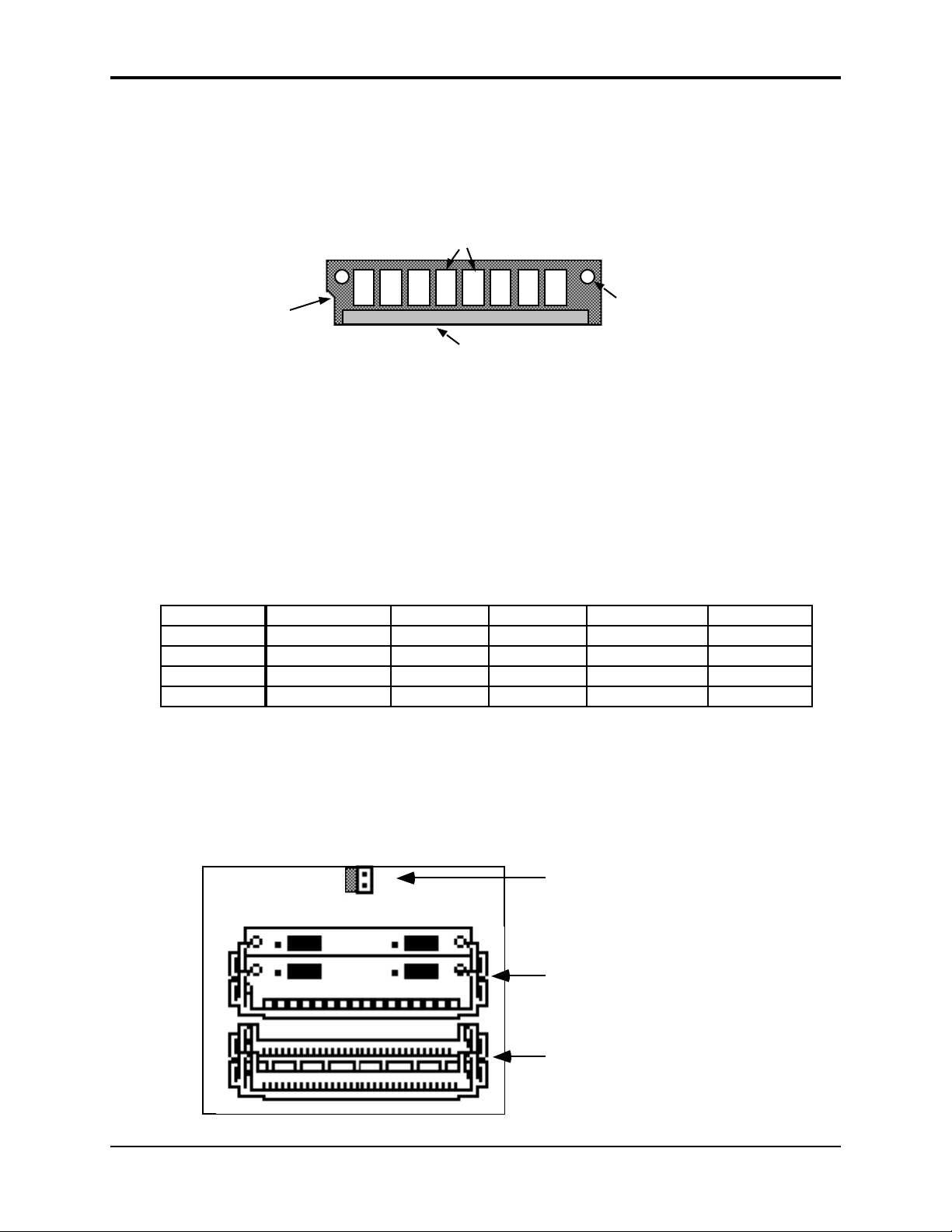
MEM EXP JMP
Standard SIMM Slots
What is a SIMM?
SIMM is an acronym which stands for Single In-line Memory Module. SIMMs have become the
industry standard used by most computers (both IBM and Mac compatible) to expand the
computer’s memory. Because of this, SIMMs are readily available in most computer software
stores, and from mail order organizations. The ASR-10 memory, like a computer, is also
expanded using SIMMs.
Drams (amount varies)
Alignment
Notch
Internal Memory
As it comes out of the box, the ASR-10 contains 2 MegaBytes or 1 MegaWord of internal memory
(a word is one single sample, or 16 bits). That’s enough for 31.5 (mono) or 15.75 (stereo) seconds
of sampling at a 29.8 KHz sample rate, or about 400,000 notes of sequencer memory.
This internal memory is shared by sounds and the sequencer. The memory is distributed
dynamically between instruments and sequences, which means that the more sounds you have in
memory, the less sequencer memory you have, and vice versa.
Expanding the ASR-10 Memory
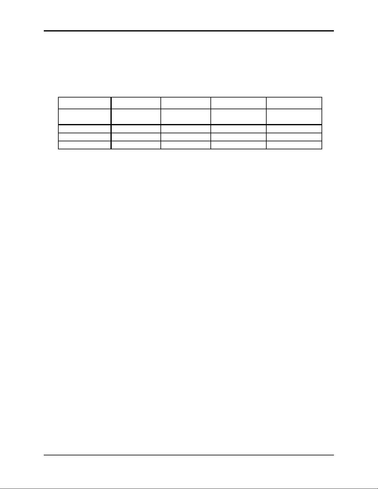
If you want to expand the memory, the ASR-10 can address up to 16 MegaBytes/8 MegaWords,
using industry standard 1m x 8 or 4m x 8 non-parity SIMMs. There are five different memory
allocations, as shown below:
SIMMS 1m x 8 (standard) 4m x 8 1m x 8 1m x 8 & 4m x 8 4m x 8
SIMMS Used two two four two & two four
MegaBytes 2 8 4 10 16
MegaWords 1 4 2 5 8
Blocks 3,800* 16,000* 7,900* 20,000* 31,000*
* Actual block count may vary due to different O.S. Versions.
Latching Hole
Edge Connector
Accessing SIMMs
To access the SIMMs in your ASR-10, make sure all cables, especially the power cable, are
unplugged from the ASR-10. Turn the unit upside down on a soft surface with the keys facing
away from you. Remove the two screws holding the trap door and remove the trap door from
the bottom of the ASR-10. As it comes from the factory, the ASR-10 would look like this
underneath the trap door:
STD
EXP
Jumper is connected for
STANDARD SIMM Memory.
Move to the other pins when
using Expansion SIMM Slots.
Two 1-MegaByte SIMMs
Expansion SIMM Slots
Expansion slots are empty
adding expansion memory
Move jumper when
14 About Memory
Page 26
You will notice that there are two slots with SIMMs installed, and two slots that are empty.
These empty slots are called Expansion SIMM Slots, and are used for adding additional SIMMs
(when expanding the memory). Directly above the Standard SIMM Slots, you will find the
Memory Expansion Jumper.
About the Memory Expansion Jumper
The Memory Expansion Jumper allows you to access the information in the Expansion SIMM
Slots. It must be moved to the EXP (Expansion) pins in order for any SIMMs plugged into the
expansion slots to be recognized. If you do not have any SIMMs plugged into the Expansion
slots, the Memory Expansion Jumper must be installed on the STD (Standard) pins, or the ASR-10
will not boot up (display will be blank).
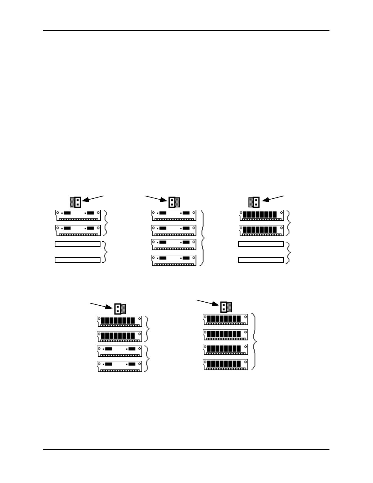
Installing SIMMs
Memory is user-installable in 1, 2, 4, 5, and 8 MegaWord configurations, with 1 and 4 MegaByte
SIMMs, as shown below. There are only five possible memory configurations available on the
ASR-10, as shown in the diagram:
Section 1 — Controls and Architecture
1 MegaWord
Jumper is connected
to STD (Standard) pins
Two
1-MegaByte
SIMMs
(Standard Slots)
Expansion
slots
empty
(as shipped from the factory)
5 MegaWords
Jumper is connected
to EXP (Expansion) pins
2 MegaWords
Jumper is connected
to EXP (Expansion) pins
8 MegaWords
Jumper is connected
to EXP (Expansion) pins
Two
4-MegaByte
SIMMs
(Standard Slots)
Two
1-MegaByte
SIMMs
(Expansion Slots)
Four
1-MegaByte
SIMMs
4 MegaWords
Jumper is connected
to STD (Standard) pins
Two
4-MegaByte
SIMMs
(Standard Slots)
Expansion
Slots
empty
Four
4-MegaByte
SIMMs
THESE ARE THE ONLY CONFIGURATIONS THAT WILL WORK PROPERLY! Any other
configurations will not yield the maximum memory available, or provide the optimal
performance.
About Memory 15
Page 27
Section 1 — Controls and Architecture ASR-10 Musician’s Manual
About the SIMM Socket
The SIMM socket uses the pins on the end of the latching posts to hold the SIMM in place. The
alignment notch on the SIMM prevents it from being installed backwards. Once installed, the
retaining posts hold the SIMM in place securely, preventing it from dropping out of the socket
inside the ASR-10.
ASR–10 SIMM Socket
Latching Posts
Retaining Post
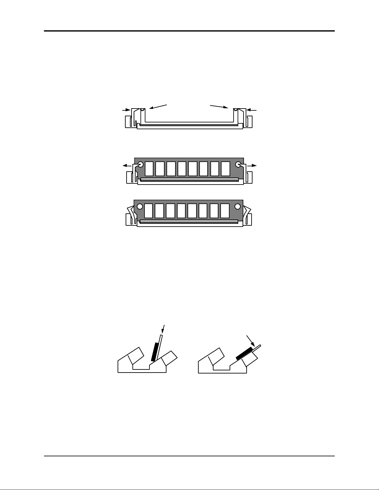
To Remove a SIMM from a SIMM Socket:
Bend the two retaining posts out of the way…
just far enough to remove the SIMM
• Carefully spread open the retaining posts found on each end of the SIMM. Only spread the
posts as far apart as needed to clear the board; these posts can easily break if too much force is
applied. If broken, it will be very difficult to secure a new SIMM back into that socket. We
suggest spreading one post at a time; that way it’s easier to control the amount of pressure
being applied to remove the SIMM.
• Once the retaining posts are out of the way, tilt the SIMM toward you, and lift up and out of
the socket.
Retaining Post
To Install a SIMM into a SIMM Socket:
SIMM Installation - Side View
Push
Step 1
• Place the connector edge of the SIMM into the SIMM Socket, pressing down slightly. The
latching holes on each end of the SIMM will line up with the latching posts when the SIMM is
seated properly.
• Tilt the SIMM back into the socket until the retaining posts snap in front of the SIMM. A
properly installed SIMM should look like this:
Press until SIMM
locks into position
Step 2
16 About Memory
Page 28
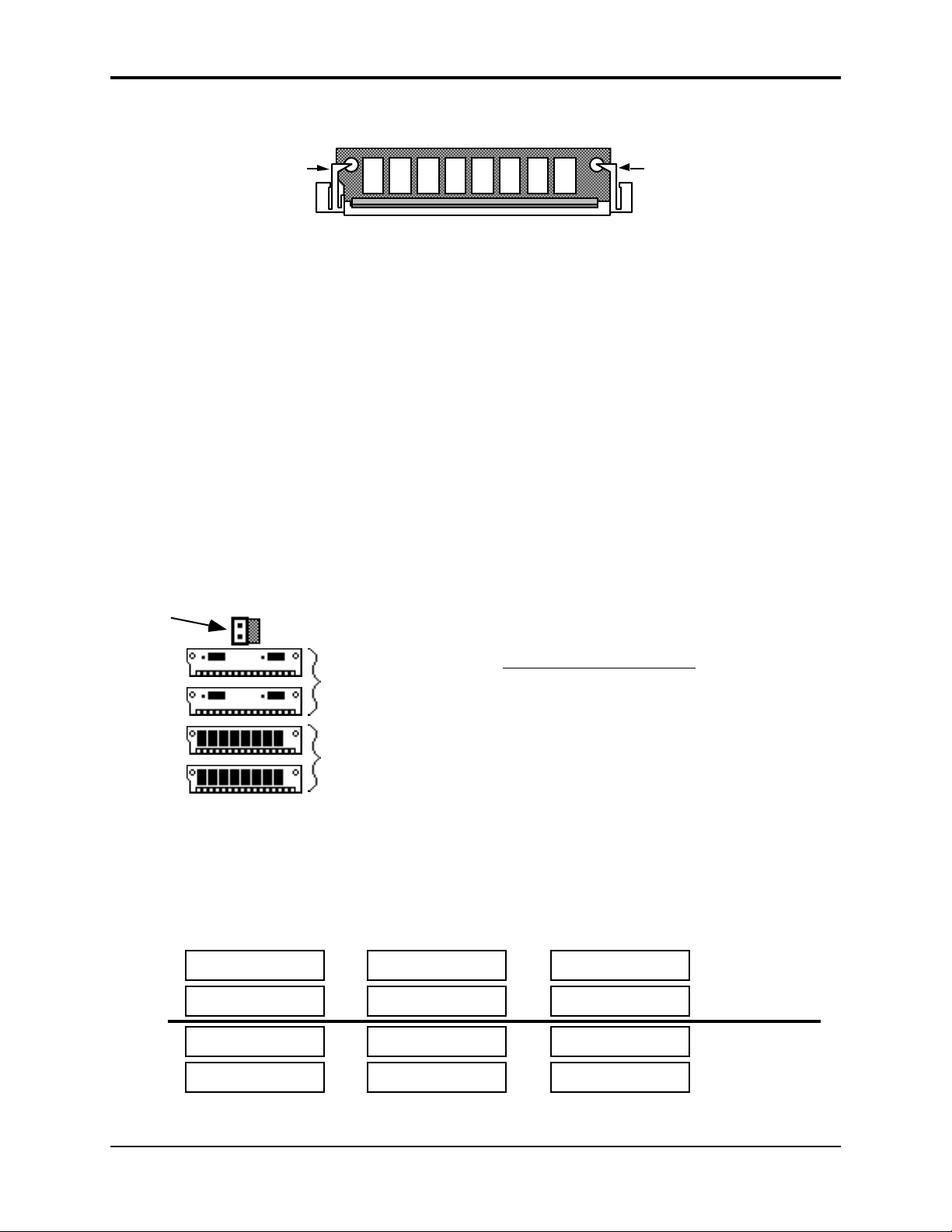
Section 1 — Controls and Architecture
Proper SIMM Installation
Retaining Post
• Reinstall the trap door with the original screws. To verify that you’ve expanded your memory
correctly, after powering up the ASR-10, press Edit, then System•MIDI and scroll until the
display shows FREE SYSTEM BLOCKS= (expanded memory amount in blocks). See the
memory allocation chart (found earlier) for the proper number of blocks for each
configuration.
Warning
The ASR-10 was designed to use 1m x 8 or 4m x 8 non-parity SIMMs (not 1m x 9 or 4m x 9 parity
SIMMs). We do not recommend using parity SIMMs. These SIMMs may not operate properly,
and may cause damage to the ASR-10.
Important Information about SIMMs
• When adding memory, only install D-RAM SIMMs in the expansion slots. The ASR-10 will
not accept static RAM or ROMs.
• If SIMMs are installed in a less than optimal configuration, the display will read SIMMS IN
WRONG SOCKETS after booting. If this message is displayed, you should power off and
check the SIMMs configuration. Here is a example of what could be the most likely
installation mistake:
Jumper is connected
to EXP (Expansion) pins
Retaining Post
Two
1-MegaByte
SIMMs
(Standard Slots)
Two
4-MegaByte
SIMMs
(Expansion Slots)
• Any configuration which does not use two or four SIMMs will not work (the system will not
even boot up).
• Any combination of SIMMs in which there are two different kinds of SIMMs in the standard
slots and/or two different kinds of SIMMs in the expansion slots will not work properly. The
following diagram shows some examples of incorrect configurations:
Incorrect Configuration
This configuration can cause continuous
noise and distortion on sounds or when
sampling/monitoring Audio Tracks.
Incorrect Configurations
1-MegaByte SIMM
4-MegaByte SIMM
4-MegaByte SIMM
1-MegaByte SIMM
4-MegaByte SIMM
1-MegaByte SIMM
4-MegaByte SIMM
1-MegaByte SIMM
4-MegaByte SIMM
1-MegaByte SIMM
1-MegaByte SIMM
4-MegaByte SIMM
Standard
Slots
Expansion
Slots
• These incorrect configurations of 1 and 4 MegaByte SIMMs could produce inaccurate
About Memory 17
Page 29

Section 1 — Controls and Architecture ASR-10 Musician’s Manual
information concerning the number of blocks, or noise and distortion.
• If the jumper is not moved from the “STD” position to the “EXP” position, no memory in the
expansion slots will be recognized. The wrong number of blocks will be displayed on the
Edit/System•MIDI page.
• If the jumper is moved from the “STD” to the “EXP” position and there are no SIMMs in the
expansion slots, the system will not boot up (display will be blank).
• 1m x 9 or 4m x 9 parity SIMMs (for IBM PC compatibles) should not be used. Only 1m x 8 or
4m x 8 (Macintosh) SIMMs should be used.
Troubleshooting Memory Expansion
If the correct number of blocks is not displayed on the Edit/System•MIDI page:
1. Make sure that there is no mix-up between 4m x 8 and 1m x 8 SIMMs (or that the store did not
sell you the wrong parts).
2. Check that the jumper is in the correct position.
3. Check that you are using one of the five proper configurations. Improper configurations may
work, but they will not work properly.
Make sure that you are careful when removing the SIMMs. If the plastic retaining posts are
broken, the SIMMs will not stay in place, and the main board will have to be replaced at an
Authorized ENSONIQ Repair Station (a costly error).
An Important Note About ElectroStatic Discharge
SIMMs are susceptible to ElectroStatic Discharge (ESD) commonly known as “static.”
ElectroStatic Discharge can destroy or damage SIMMs. In order to minimize the possibility of
causing ESD damage, here are some procedures you can follow when installing SIMMs:
1. Before installing SIMMs, you should be grounded by using a ground strap to discharge any
static electric charge built up on your body. The ground strap attaches to your wrist and a
ground source allowing your hands to be free to work.
2. Avoid any unnecessary movement, such as scuffing your feet when handling SIMMs, since
most movement can generate additional charges of static electricity.
3. Minimize the handling of the SIMMs. Keep them in their static free packages until needed.
Only transport or store the SIMMs in their protective packages.
4. When handling the SIMMs, avoid touching the connector pins. Try to handle the SIMMs by
the edges only.
If you have any questions concerning the use of SIMMs, the ASR-10, or for additional technical
support, please contact ENSONIQ Customer Service at (610) 647-3930 Monday through Friday
9:30 a.m. to 12:15 p.m. and 1:15 p.m. to 6:30 p.m. Eastern Time.
18 About Memory
Page 30
About Instruments
We refer to ASR-10 sounds as Instruments. A grand piano, an electric bass, a multi-sampled drum
set, a complete string section — each of these would be an example of an instrument. You can
load up to eight instruments into the ASR-10, memory permitting, and have instant access to any
or all of them.
Each instrument contains four different Patches that are selected with the Patch Select buttons.
These patches allow a single instrument to have four different inflections, voicings, tunings, or
synth-type program variations all available at the press of a button.
An instrument can be any size (within the limits of memory) — one instrument might consist of a
single WaveSample that plays over the entire keyboard, while another might have as many 127
different WaveSamples.
For controlling remote devices, you can create an instrument that contains no samples at all and
assign it to play only out MIDI, on a particular MIDI Channel.
Loading an Instrument
You can load up to eight different instruments into the ASR-10 at once (within the limits of
memory). First, insert a disk containing one or more instrument files into the disk drive.
• Press Load. The LOAD indicator flashes.
• Press Instrument. The display looks like this:
Section 1 — Controls and Architecture
LOAD INST STOP
When the LOAD indicator is flashing, the ASR-10 is showing you disk files (think of it as a
question mark — the ASR-10 is saying “Load the file showing on the display?”). Pressing the
Up/Down Arrow buttons takes you through the files on the disk. If there are none, the display
will read “NO INST OR BANK FILES.”
Whenever a disk file is displayed as above, you can press the Left or Right Arrow button to see
the size of that file in Blocks (a Block is 256 samples; 4 Blocks=1K sample words). Press the Left
or Right Arrow button again to return to the file name.
• Use the Data Entry Slider or the Up/Down Arrow buttons to view the various instrument files
on the disk. Each file has its own File Number. When an instrument file is showing, the INST
indicator is lit. The BANK Indicator will light when a bank file is showing.
• Find the instrument you want to load, and press Enter•Yes. The display will say PICK
INSTRUMENT BUTTON. The ASR-10 is asking in which instrument location you want to
load the sound into.
• Press any of the eight Instrument•Sequence Track buttons. The ASR-10 will begin
immediately loading the instrument into the selected location. The display reads LOADING
FILE… and the left red LED flashes while the instrument is being loaded.
About Instruments 19
Page 31

Section 1 — Controls and Architecture ASR-10 Musician’s Manual
LOAD INST STOP
Once the instrument has been loaded, the display briefly shows “FILE LOADED.” The left red
LED above the Instrument•Sequence Track button stops flashing and remains solidly lit,
indicating that there is now an instrument loaded in that location which can be selected by
pressing that button.
If you tell the ASR-10 to load an instrument into a location that already has an instrument loaded
(left red LED lit), the new instrument will be loaded into that location and the one that was there
will be automatically deleted.
If You Run Out of System Memory
You might have to delete an instrument(s) before loading the new one. If there are already one or
more instruments loaded into the ASR-10, there might not be enough free memory to load the
new one. In this case, the display will say PICK INST TO DELETE. At this point you have three
choices. You can:
1. Press any loaded Instrument•Sequence Track button. That instrument will be deleted from
memory and the new one will be loaded; or,
2. Press Enter•Yes. The ASR-10 will delete an instrument (or instruments, as needed) for you,
starting from the highest-numbered one in memory; or,
3. Press Cancel•No. The load command will be canceled with no harm done.
Note: You can continue to select and play existing instruments while the new one loads. No more
“down-time” waiting for the next sound to load. With the ASR-10, you can be loading the next
sound you need while continuing to play the currently selected sound.
Deleting an Instrument from the Internal Memory
Sometimes you will want to delete an instrument from memory — to free up some memory for
sampling, for instance. Make sure you have saved the instrument to disk before deleting it.
Here’s how:
• Verify that the instrument you want to delete is selected.
• Press Command, then Instrument.
• Press the Right Arrow button repeatedly until the display reads DELETE INSTRUMENT.
• Press Enter•Yes. The display asks DELETE <INST NAME>?
• Press Enter•Yes (or press Cancel•No to abort the procedure).
Tip: There is a “shortcut” method for deleting an instrument from internal memory. First, press the
Instrument•Sequence Track button of the instrument you would like to delete. Then, while
holding down the Instrument•Sequence Track button, press Cancel•No.
20 About Instruments
Page 32

Section 1 — Controls and Architecture
About Banks
Banks provide a way to load a whole group of instruments and sequences into the ASR-10 with a
few button presses. When you save a bank to disk, it is like taking a “snapshot” of the contents of
the ASR-10 Internal memory — the bank file contains information about which instruments are
loaded into which of the eight Instrument•Sequence Track locations, and which song and
sequences (if any) are currently loaded in Internal Memory. When you load a bank, the ASR-10
will set up Internal Memory in the same state it was in when you saved the bank file, loading
those instruments into the same locations and, if you choose, loading the song with its related
sequences. A bank will also save any Performance Presets you have created.
For example, you might have a piano loaded into Instrument•Sequence Track 1, a bass in
Instrument•Sequence Track 2, and drums in Instrument•Sequence Track 3, and you have
created a number of Performance Presets containing different keyboard configurations of those
instruments. Let’s say you also have in memory a song, which is composed of 12 sequences. If
you now save the contents of memory as a bank, you can later call up this exact setup by loading
the bank.
The bank file on a disk doesn’t contain the actual instrument and sequence files — it is just a set
of instructions telling the ASR-10 what files to load and where to load them. All the instruments
and the song in a bank must be saved to disk individually before saving the bank.
Note: Any instruments already loaded into locations not used by the bank will be left intact (memory
permitting). You can select and play such instruments while the bank loads.
To Load a Bank
• Press Load, then Instrument.
• Use the Up/Down Arrow buttons to view the different files.
When a bank file is showing, the BANK indicator lights on the display along with the INST
indicator.
• Once a bank file is showing, press Enter•Yes. The ASR-10 will begin loading the instruments
and the song data. As it loads each instrument the display tells you what it’s doing. As soon
as any of the instruments are finished loading, you can select that instrument and play while
the rest of the bank loads.
At some point in the loading process, you may encounter the following message:
This prompt is informing you that an instrument or song saved as part of the bank is on a
different disk than the disk currently in the drive. When this occurs:
• Eject the current disk in the disk drive and replace it with the disk that matches the Disk Label
ID requested by the ASR-10.
LOAD INST STOP
BANK
FILE 4 SOUND BANK 1
INST STOP
LOAD
BANK
INSERT <DISK NAME>-ENTER
About Banks 21
Page 33

Section 1 — Controls and Architecture ASR-10 Musician’s Manual
• Press Enter•Yes. The ASR-10 will resume loading until completed, or until the point when it
needs another disk.
• When it has finished loading the instruments, the ASR-10 will load the song (if any) and then
set up any copied instruments included in the bank.
Playing Instruments
• First, press Load until LOAD is solidly lit in the display to make sure you are in LOAD Mode.
Now we’ll look at the eight Instrument•Sequence Track buttons and how they function in
LOAD Mode.
1
32
Instrument•Sequence Track Buttons
These buttons represent a location or “slot” into which an instrument can be loaded. The two
LEDs above each button tell you if there’s an instrument loaded into that location and whether
it’s selected, deselected or “stacked.”
• The red LED lights to indicate that an instrument is loaded into that location and can be
selected by pressing that button. In the illustration above, we see that instruments are loaded
into locations 1, 2, 3, and 4. If none of the red LEDs are lit, no instruments are loaded. The red
LED flashes while an instrument is being loaded from disk.
• The yellow LED lights when the instrument is selected (i.e. active on the keyboard). You select
an instrument by pressing its Instrument•Sequence Track button. Pressing the button a
second time “deselects” the instrument, turning off the yellow LED. In the illustration,
Instrument #2 is selected. If none of the yellow LEDs are lit, that means that no instruments
are selected, and playing the keyboard won’t make any sound.
• The yellow LED flashes when the instrument is “Stacked” with one or more instruments. An
instrument that is stacked will play simultaneously with any other instruments that are
selected or stacked. You stack an instrument by pressing its button twice in rapid succession (or
“double-click” on the Instrument•Sequence Track button, to borrow a term from those
computers that use a “mouse”). In the illustration above, Instrument•Sequence Track # 3 is
stacked with Instrument•Sequence Track #2. You will hear both instruments when you play
the keyboard (wherever their keyboard ranges overlap, that is).
6
5
4
L
S
8
7
• Select a loaded instrument (one whose red LED is lit) by pressing its Instrument•Sequence
Track button. The display now looks like this:
INST STOPLOAD
Once you have loaded one or more instruments, select the instrument you want to play by
pressing the appropriate Instrument•Sequence Track button. The LOAD indicator stops
flashing, and the ASR-10 shows you the name of the selected instrument, and its volume setting.
You can adjust the volume of the instrument with the Data Entry Slider or the Up/Down Arrow
buttons. This lets you easily balance the levels of several instruments when splitting the
keyboard or stacking sounds. If any other instruments are loaded, you can select them in the
same way and adjust their volumes. Each time you select an instrument, its name and volume
setting will appear in the display.
22 About Banks
Page 34

Section 1 — Controls and Architecture
Note: Instruments can be played from an external MIDI controller, without being selected, when
Edit/System•MIDI, MIDI IN MODE=MULTI or MONO-B see Section 2 — System•MIDI for
details.
Tip: When TRANSMIT ON = INST CHAN, on the Edit/System•MIDI page, editing the VOLUME
value will transmit MIDI Volume messages (Controller #7) on the selected Instrument•Sequence
Track’s MIDI OUT CHANNEL (on the Edit/Instrument page).
Tip: To adjust the volume of each loaded Instrument without selecting them, first select one
instrument, and then use the Left/Right Arrow buttons to view the volumes of the other
Instruments that are loaded.
• Try selecting different instruments. Try “double-clicking” to stack instruments. Click once on
a selected or stacked instrument to deselect it.
• Pressing the Load button again returns you to viewing disk files (LOAD flashing). You can
also press Cancel•No to toggle back and forth between looking at disk files (LOAD flashing)
and looking at instruments in the internal memory (LOAD indicator lit but not flashing).
Keyboard Range (How Instruments Share the Keyboard in Load Mode)
Whenever the ASR-10 is in Load Mode (which is the normal performance mode) you are not
limited to one instrument on the keyboard at a time (or two, or three for that matter). Each
instrument has a Keyboard Range, which is the section of the keyboard that it will occupy when
selected.
The range of an instrument can be as much as the full 127 keys of the MIDI Specification (for
playing the ASR-10 from an external controller via MIDI) or as little as a single key. Up to eight
instruments can inhabit the keyboard in a way that might be termed a “Pile o’ Instruments.”
Imagine four pieces of paper, each a different size, piled on top of each other:
1
2
3
4
In the picture above, sheet #2 is on top of the pile — all of it is showing. The other three sheets
are partially covered up. Now suppose we could magically bring sheet #3 up to the top of the
pile. The pile would look like this:
Playing Instruments 23
Page 35

Section 1 — Controls and Architecture ASR-10 Musician’s Manual
3
1
3
2
4
Now all of #3 is showing:
Numbers 1, 2 and 4 are partially
showing, partially covered up.
If we now bring #4 to the top of
the pile, Numbers 1 and 2 are
still partially visible, but #3 is
completely covered up.
1
2
4
So it is with instruments loaded into the ASR-10 in Load mode. When you select an instrument,
it is brought to the top of the pile. That is, you will hear the most recently selected instrument over
its whole range when you play the keyboard. Any previously selected or stacked instruments
will be “covered up” wherever their ranges overlap with that of the newly selected one.
Wherever an instrument is not “covered up,” it will continue to play on the keyboard. So you
can see that “splitting” the keyboard is as easy as selecting two or more instruments with
different (or overlapping) ranges.
• All instruments that are selected (yellow LED lit) are “on the pile,” even if they are partially
covered up by another instrument.
Now let’s try the “sheets of paper” analogy in terms of instruments on the keyboard. Suppose
you have two instruments loaded into the ASR-10:
• Instrument #1 is a piano sound, whose range is the entire keyboard;
• Instrument #2 is a bass sound, whose range is only the bottom two octaves.
The ranges of the two instruments can be shown like this:
Instrument #1 — Piano
Instrument #2 — Bass
24 Keyboard Range
Page 36

Section 1 — Controls and Architecture
If you select the piano, it will play over the whole keyboard, covering up the bass entirely:
Piano
Bass
Now you select the bass. This brings it to the top of the pile, and it covers up the piano, but only
in the region where their ranges overlap (the bottom two octaves):
Bass
Piano
If you play now, you will hear the bass in the bottom two octaves and the Piano over the rest of
the keyboard. If you deselect the bass (by pressing its instrument button again) its yellow LED
goes out and it returns the whole keyboard range to the piano.
This same logic applies no matter how many instruments are loaded and selected. Whichever
one you select comes to the “top of the pile.”
Note: The “Pile” described here only exists in Load Mode. In Edit and Command modes, only one
instrument can be selected at a time.
Stacking Instruments
With either the bass or the piano selected, double-click the other Instrument•Sequence Track
button. Now in the lower two octaves you hear the bass and the piano.
Bass and Piano Stacked
Instruments that you “stack” by double-clicking their instrument buttons will play simultaneously
with whatever other instruments are on the pile. Selecting another instrument (by pressing its
Instrument•Sequence Track button and not by double-clicking), will bring that instrument to
the top, covering up any stacked instruments as well as any selected ones. Up to all eight
instruments can be stacked at once.
Additional Notes:
• Whenever a selected instrument is covered up completely by the selection of another, its
yellow LED goes out — it is automatically deselected.
• Up to all eight instruments can be selected and can play on some part of the keyboard at once,
as long as none is covered up completely.
• You can reset any instruments key range. This is done on the Edit/Instrument page.
Keyboard Range 25
Page 37

Section 1 — Controls and Architecture ASR-10 Musician’s Manual
Loading Sequencer Data
There are two ways that ASR-10 Sequencer data can be stored on a disk:
• SONG File. A song file contains a song and all its related sequences. Loading a song file from
disk will completely erase the current contents of the ASR-10 sequencer memory, replacing
whatever is there with the song and sequences from the disk file.
• SINGLE SEQUENCE File. This type of file contains just one sequence. Loading a single
sequence file will not erase the sequencer data already in memory — the new sequence simply
becomes one more sequence in the internal memory which can be selected or used as a step in
a song. There can be up to 80 sequences in memory at once.
Loading a Song or a Single Sequence from Disk
Both types of sequencer files are accessed from the Load/Seq•Song page.
• Press Load, then press Seq•Song.
The LOAD indicator flashes, meaning that the ASR-10 is showing you disk files.
• Press the Up or Down Arrow button until the file you want to Load is showing on the display:
LOAD STOP
SEQ
SONG
FILE 6 BLUES IN F
When a Song file is showing, the SONG indicator lights next to the SEQ indicator.
LOAD STOP
SEQ
FILE 8 FIRST VERSE
When a single Sequence file is showing, only the SEQ indicator lights.
• Press Enter•Yes to load the sequencer file showing on the display. After you have loaded a
Important:
Remember that loading a song or sequence does not ensure that the right instruments are loaded
into the proper Instrument•Sequence Track locations. Each track of each sequence will play
whatever instrument is in that location at the time. The way to make sure everything is in the
right place is to save the contents of memory (including the song) as a bank.
song or sequence, it is automatically selected.
26 About the Sequencer
Page 38

Selecting a Sequence/Song
Press the Edit button, then the Seq•Song button. The following screen will appear:
Section 1 — Controls and Architecture
Current Sequence
or Song
This screen is where you select a sequence or the song. With the selected sequence or song
underlined (as shown above), use the Up/Down Arrow buttons or the Data Entry Slider to select
a different sequence or song. You can always get back to this screen by double-clicking the
Seq•Song button (when in Edit mode). The display will indicate whether a song is selected:
This will appear when a Song
Playing a Sequence/Song
Try selecting a sequence, and pressing the Play button in the sequencer section, to the right of the
display. The selected sequence will begin to play.
EDIT
EDIT
SEQ
is selected.
SEQ
STOP
Bar and Beat Location within
current Sequence or Song
SONG
STOP
While one sequence is playing you can select another one. You will see the name of the new
sequence in the display, but the original one will continue to play. When the first sequence is
finished, the sequencer will switch to the new sequence, and it will play. In this fashion you can
string sequences together in real time, as they play.
Press the Stop•Continue button or the Left Foot Switch to stop the current sequence.
About the Sequencer 27
Page 39

Section 1 — Controls and Architecture ASR-10 Musician’s Manual
Saving Sequencer Data
Saving a Single Sequence to Disk
Use the SAVE CURRENT SEQUENCE command to save a single sequence.
• On the Edit/Seq•Song page, select the sequence you want to save.
• Insert a formatted disk into the drive.
• Press Command, then press Seq•Song.
• Press the Left or Right Arrow button until the display reads SAVE CURRENT SEQUENCE.
• Press Enter•Yes.
• Edit the Sequence Name (if needed):
SEQ
CMD
The display shows the current name of the sequence, with a cursor (underline) beneath the first
character. If you want to give the sequence a new name, do so at this time. Use the Data Entry
Slider or the Up/Down Arrow buttons to change the underlined character, then press the
Left/Right Arrow buttons to move the underline. Repeat until the display shows the name you
want (if you don’t need to rename the sequence, just skip this step).
• Press Enter•Yes. The display will read SAVING <FILE NAME> while the sequence is being
saved.
• If there is already a sequence file with the same name on the disk, the display will ask DELETE
OLD VERSION? Press Enter•Yes to save the sequence, replacing the one on the disk. Or
press Cancel•No to abort the procedure.
• If there is not enough free space on the disk, the display will say NOT ENOUGH DISK
SPACE. Save the sequence to another disk (or delete some files from the disk).
• If you try to SAVE CURRENT SEQUENCE while the song is selected, the ASR-10 will not
execute the command, responding USE SAVE SONG + ALL. Again, make sure the sequence
is selected before trying to save it.
STOP
28 About the Sequencer
Page 40

Section 1 — Controls and Architecture
Saving a Song (along with all Sequences) to Disk
Once you have created a song or made changes to an existing one, you can save the song to a
formatted ASR-10 disk. In addition to saving the song itself, the SAVE SONG + ALL SEQS
command saves all the individual sequences currently in memory (whether they are part of the
song or not). To save a song:
• Insert a formatted disk into the drive.
• Press Command, then press Seq•Song.
• Press the Left or Right Arrow button until the display reads SAVE SONG + ALL SEQS.
• Press Enter•Yes.
• Edit the song name (if needed):
SEQ
CMD
The display shows the current name of the song, with a cursor (underline) beneath the first
character. If you want to give the song a new name, do so at this time. Use the Data Entry Slider
or the Up/Down Arrow buttons to change the underlined character, then press the Left/Right
Arrow buttons to move the underline. Repeat until the display shows the name you want (if you
don’t need to rename the song, just skip this step).
• Press Enter•Yes. The display will read SAVING <SONG NAME> while the song is being
saved.
• If there is already a song file with the same name on the disk, the display will ask DELETE
OLD VERSION? Press Enter•Yes to save the song, replacing the one on the disk. This is for
updating songs to which you have made changes. Or press Cancel•No to abort the
procedure.
• If there is not enough free space on the disk, the display will say NOT ENOUGH DISK
SPACE. Save the song to another disk (or delete some files from the disk).
• Note that the song and all sequences in memory are saved as one file. You cannot extract a
single sequence from a song file and load it separately. If you want access to a sequence
individually, you must first load the song into the internal memory, and then save the
individual sequence using the SAVE CURRENT SEQUENCE command.
STOP
Deleting a File from Disk
Deleting of disk files is done from Load mode. To delete (erase) a file from a disk:
• Press Load, followed by the page button (Instrument, Seq•Song, System•MIDI, or Effects)
for the type of file you want to delete.
• Press the Up or Down Arrow button until the file you want to delete is showing on the
display.
• While holding down the Load button, press Cancel•No. The display will ask DELETE <FILE
NAME>?
• Press Enter•Yes. Press Cancel•No to abort this procedure.
About the Sequencer 29
Page 41

Section 1 — Controls and Architecture ASR-10 Musician’s Manual
Managing Your System Headroom
The ASR-10’s 16-bit stereo output converters provide 96dB of dynamic range. This figure of 96dB
is referred to as the system headroom. Since the ASR-10 is capable of playing 31 notes of
polyphony, this 96dB of system headroom must be divided amongst these 31 voices. If the
output level of all sustaining voices exceeds 96dB, this will result in clipping. As a result, normal
sample playback is attenuated by 12dB to allow multiple voices to sustain simultaneously
without clipping, as shown below:
With Attenuation (BOOST=OFF)
Normal Sample Attenuated Sample
Normal Sample
Playback Attenuation
-12dB
-12dB
Without Attenuation (BOOST=ON)
Normal Sample
Normal Sample Playback
without Attenuation
Combined Samples
still remain within
the system
headroom
Combined Samples
will result in
clipping
There may be times that this attenuated level does not offer enough perceived loudness for a
certain type of sound. For example, percussion sounds only play at their peak volume for a brief
instant before decaying quickly to a lower volume. As a result, it is often desirable to have that
peak volume be even louder than the loudest attenuated level. This is the purpose for the
Edit/Amp BOOST parameter. It provides a 12dB boost in volume to allow a WaveSample to use
all 96dB of headroom. Since it is unlikely that two percussion sounds will both use the entire
96dB of headroom at the same exact instant, it is a relatively safe assumption that turning boost
on for multiple percussion sounds will not result in clipping.
30 Managing Headroom
Page 42

Section 1 — Controls and Architecture
Normal Sample Attenuated Sample
Drum Sample
The BOOST parameter should
Normal Sample
Playback Attenuation
-12dB
-12dB
Drum Sample Playback
without Attenuation
not be turned on for all WaveSamples.
Combined Samples
still remain within
the system
headroom
Sustaining sounds can remain at their peak volume for as long as a key is held down. As a result,
if boost is turned on for a sustaining sound, it is very likely that playing multiple notes will result
in clipping, even if the notes are not all started at the same time.
After sampling with REC SRC= MAIN-OUT, the Edit/Amp BOOST parameter is automatically
set to ON for the new WaveSample. This is done because you have sampled a signal that was
attenuated by 12dB and now the sample will be played back attenuated by another 12dB.
Turning BOOST= ON, compensates for this effect. As a final step, after sampling the MAIN
OUT, it is recommended that you optimize your use of headroom by setting the Edit/Amp
BOOST= OFF, and performing the Command/Amp NORMALIZE GAIN command on the new
WaveSample.
The key to managing your headroom is to determine which non-sustaining sounds will be the
loudest, and set the BOOST parameter ON only for those sounds.
Audio Track Headroom
The Audio Tracks are permanently set to BOOST= ON. To prevent clipping, the Edit/Track MIX
parameter for the Audio Tracks defaults to MIX= 60. When MIX= 99, the Audio Track will use
the entire 96dB dynamic range. If you hear clipping when monitoring audio input on an Audio
Track, first adjust the Mic/Line Switch and the Input Level trim control so that the red Input
Level Peak LEDs only light occasionally (the red Peak LEDs light at 6dB below clipping), and
then set the Edit/Track MIX parameter to a lower value.
Managing Headroom 31
Page 43

Section 1 — Controls and Architecture ASR-10 Musician’s Manual
Parameter Illustrations
The ASR-10 accesses parameters and commands through Pages. Each page is accessed by two
button presses, the first being a Mode button and the second a Page button. Most parameters
will also have a Direct-Dial number. This number can be pressed immediately after pressing the
proper Mode and Page button to get to a specific parameter directly, bypassing scrolling with the
Left/Right Arrow buttons.
When describing parameters or commands in this manual, parameter illustrations are used to
communicate the location of the parameter and how to get there. For example:
Page Name Parameter Name(s) and description(s)
m m
EDIT PATCH (Layer Enable/Disable)
INST Press Edit / Instrument / 0
i
Directions to locate
These illustrations not only help to divide the manual into easy to locate sections for each screen,
they also provide the following three important pieces of information about the parameter being
discussed:
• Page Name — The page in which the parameter resides. In this case, it is the
Edit/System•MIDI page.
• Parameter(s) — This tells you the name of the parameter or parameters as they’re listed in that
screen.
• Directions to Locate — This tells you how to get to the parameter screen. The directions will
contain the Direct-Dial number for the parameter if one exists. If not, it will advise you to
scroll to the parameter.
32
Page 44

Section 2 — System•MIDI
These pages contain parameters and commands that affect the ASR-10 as a whole.
Edit/System•MIDI Page
This page contains global system and MIDI parameters. Due to the large number of parameters
on this page, not all parameters have a direct dial number. Those that do will have that number
listed in its parameter illustration. Parameters without direct dial numbers can be accessed with
the Left/Right Arrow buttons.
Tip: By double-clicking the System•MIDI button in Edit mode, you can toggle between the first
System Parameter and the first MIDI parameter.
Note: The settings for most of these parameters will be saved to the O.S. disk when you perform the
SAVE GLOBAL PARAMETERS command (defined earlier).
System Parameters
EDIT
SYSTEM•MIDI
This page shows the amount of available internal memory (in blocks).
EDIT
SYSTEM•MIDI
This page shows the amount of available memory (in blocks) on the disk currently in the drive
(or on whatever SCSI Storage Device is selected as the storage device).
EDIT
SYSTEM•MIDI
Adjusts the overall master tuning of the keyboard up or down as much as one semitone. A value
of +0 will set the ASR-10 to concert A=440 tuning.
Range: -99 to +99 cents
EDIT
SYSTEM•MIDI
Use this parameter to adjust the pitch bend range. The bend range is adjustable in one-semitone
increments from 0 to 12. Each ASR-10 WaveSample can have its own bend range (which will
override the global bend range) or can use this global bend range.
FREE SYSTEM BLOCKS
Press Edit / System•MIDI / 0
FREE DISK BLOCKS
Press Edit / System•MIDI / scroll using the arrow buttons
MASTER TUNE
Press Edit / System•MIDI / 1
GLOBAL BEND RANGE
Press Edit / System•MIDI / scroll using the arrow buttons
Range: 0 to 12 semitones
Note: When MASTERTUNE and GLOBAL BEND RANGE are edited, the ASR-10 will transmit the
current value as a Registered Parameter Select message, on the MIDI BASE CHANNEL.
1
Page 45

Section 2 — System•MIDI ASR-10 Musician’s Manual
EDIT
SYSTEM•MIDI
Allows you to adjust both the pressure and velocity response of the keyboard to match your
playing style and technique. For each of the four velocity settings SOFT, MED, FIRM, HARD
there are four pressure thresholds 1, 2, 3, 4, for a total of 16 available settings. The pressure
threshold can be varied between 1 (minimum force required to bring in pressure) and 4
(maximum force required to bring in pressure).
• SOFT 1, SOFT 2, SOFT 3, SOFT 4 — This is for someone with a light touch. On any of these
settings, a minimum of velocity is required to reach the maximum level of any velocitycontrolled parameter. The pressure threshold is adjustable from SOFT 1 to SOFT 4 as
described above.
• MED 1 MED 2, MED 3, MED 4 — Slightly harder keystrikes are required to reach maximum
velocity levels. The pressure threshold is adjustable from MED 1 to MED 4 as described
above.
• FIRM 1, FIRM 2, FIRM 3, FIRM 4 — These settings represent average velocity sensitivity. One
of these settings should be right for the player with an average touch. The pressure threshold
is adjustable from FIRM 1 to FIRM 4 as described above.
• HARD 1, HARD 2, HARD 3, HARD 4 — These settings are for the strong player who strikes
the keys hard. It provides the widest possible range of velocity sensitivity. The pressure
threshold is adjustable from HARD 1 to HARD 4 as described above.
EDIT
SYSTEM•MIDI
TOUCH (Velocity and Pressure Response)
Press Edit / System•MIDI / scroll using the arrow buttons
PEDAL (VOLUME / MOD)
Press Edit / System•MIDI / 2
The optional CV Pedal (model CVP-1) can be used as a volume pedal or as a modulator. When
PEDAL= VOLUME, the pedal will only affect the volume of the selected Instrument•Sequence
Track(s), and it will be transmitted via MIDI as MIDI controller #7. When PEDAL=MOD, it will
affect any modulation destination that has PEDAL selected as a modulator, and it will be
transmitted via MIDI as MIDI controller #4. When PEDAL= VOLUME the ASR-10 will still
receive PEDAL (MIDI controller #4) messages via MIDI.
Note: Some Yamaha™ TX modules (depending on the software version) receive MIDI controller #4 as
volume. If PEDAL=MOD MIDI=4, and the pedal is not plugged in, the MIDI controller #4 value
transmitted will default to 0, which could shut down the volume of the TX.
• When set to PEDAL=VOLUME MIDI=7 the optional CV Pedal acts as a volume pedal for the
selected Instrument•Sequence Track(s).
• When set to PEDAL=MOD MIDI=4 the optional CV Pedal acts as a modulation pedal, and will
cease to act as a volume pedal.
2 Edit/System•MIDI Parameters
Page 46

Section 2 — System•MIDI
EDIT
SYSTEM•MIDI
When the optional SW-10 Dual Foot Switch is plugged into the rear panel Foot Switch jack, this
page allows the Left Foot Switch to perform a variety of assignable functions. The Right Foot
Switch is permanently dedicated to function as the Sustain pedal.
• OFF — This setting makes the ASR-10 ignore the Left Foot Switch. If you are using the single
foot switch (SW-2) which came with the ASR-10, then you should keep this parameter set to
OFF (the SW-2 will only function as a sustain pedal).
• FX MODSRC — This setting allows the left foot switch to function as an effects modulation
source, assignable to any modulation destination in any effect.
• SAMPL YES — This setting allows you to initiate sampling with the Left Foot Switch. After
pressing the Sample•Source Select button, successive presses of the Left Foot Switch will
behave as though the Enter•Yes button has been pressed.
• STOP/CONT — When set to STOP/CONT, the left pedal of the SW-10 duplicates the action of
the Stop•Continue button. When in standby record, pressing the Left Foot Switch will
initiate recording.
Note: If you are using a single foot switch (SW-2 or SW-6), this parameter should be set to OFF to
prevent unexpected behaviour.
Note: If you want the SW-10 to duplicate the behavior of the Patch Select buttons, plug it into the Patch
Select jack located on the rear panel. The Patch Select jack requires a dual foot switch and will not
work properly with a single foot switch (SW-2 or SW-6).
LEFT FOOT SW
Press Edit / System•MIDI / scroll using the arrow buttons
EDIT
SYSTEM•MIDI
This parameter enables or disables the “Expert-System” auto-loop function. If the auto-loop
function is enabled, the ASR-10 will automatically go to zero crossings (with matching wave
direction) whenever you move the loop start or end pointer. This is a very useful feature because
finding zero crossings is essential to creating glitch-free loops. If the auto-loop function is
disabled, the loop start and end parameters will move in one-sample increments.
Note: AUTO-LOOP FINDING will not function on a WaveSample that exists in a stereo layer (i.e. a
layer in which STEREO LAYER LINK = ON).
AUTO-LOOP FINDING (ON/OFF)
Press Edit / System•MIDI / 3
Edit/System•MIDI Parameters 3
Page 47

Section 2 — System•MIDI ASR-10 Musician’s Manual
MIDI Parameters
Few developments in recent years have had as great an impact on the way we make music as has
the emergence of MIDI. Whether you are simply linking two keyboards together, playing a synth
from a guitar controller, or driving a rack of samplers from a drum pad controller, MIDI makes it
all possible. The evolution of MIDI has facilitated the merging of existing technologies and has
inspired the creation of new technologies. ENSONIQ has always been an industry leader in
MIDI development, and the ASR-10 embodies the latest advances in a state-of-the-art sequencer,
controller keyboard, and multi-timbral sound generator.
EDIT
SYSTEM•MIDI
Selects the Base Channel on which the ASR-10 transmits and receives MIDI messages. The base
channel is used to receive MIDI data while the ASR-10 is in POLY and MONO A modes. This is
the MIDI channel that the ASR-10 will transmit on when Edit/System•MIDI, TRANSMIT
ON=BASE CHANNEL. System Exclusive messages are always sent and received on the base
channel.
Any of 16 MIDI channels may be selected as the base MIDI channel of the ASR-10. The effect of
setting the base channel varies depending on the setting of the TRANSMIT ON= parameter, the
MIDI Mode and whether data is being transmitted or received.
Receive In POLY mode, keys, controllers, and program changes are only recognized if
Transmit The ASR-10 has two different MIDI transmitting schemes, depending on the
MIDI BASE CHANNEL
Press Edit / System•MIDI / 5
received on the base channel. In MONO A mode, program changes are received
only on the base channel. The base channel is also used in MONO A mode as the
first channel of the 8 channel range.
setting of the TRANSMIT ON= parameter. When TRANSMIT ON=BASE
CHAN, the ASR-10 always transmits only on the base channel. When
TRANSMIT ON=INST CHAN, the ASR-10 always transmits on the
Edit/Instrument, MIDI OUT CHANNEL for each Instrument.
Range: MIDI channels 1 through 16.
EDIT
SYSTEM•MIDI
• When set to INST CHAN, each of the eight ASR-10 instruments will send on its own MIDI
channel (or not at all, if assigned LOCAL status). Each instrument will have its own MIDI
program number and its own PRESSURE setting.
• When set to BASE CHAN, the ASR-10 will always transmit notes, controllers and program
changes on the Base MIDI channel and only on that channel, no matter what
Instrument•Sequence Tracks are selected or stacked.
EDIT
SYSTEM•MIDI
When TRANSMIT ON=BASE CHAN, the ASR-10 will send either Key or Channel pressure or no
pressure at all, depending on the setting of this parameter. When TRANSMIT ON=INST CHAN,
this setting is ignored and each instrument transmits pressure according to its own
Edit/Instrument PRESSURE MODE setting.
TRANSMIT ON (INST CHAN/BASE CHAN)
Press Edit / System•MIDI / 6
BASECHAN PRESSURE
Press Edit / System•MIDI / scroll using the arrow buttons
4 Edit/System•MIDI Parameters
Page 48

Section 2 — System•MIDI
• When BASECHAN PRESSURE=OFF, no pressure will be transmitted via MIDI.
• When BASECHAN PRESSURE=KEY, the ASR-10 will transmit the most expressive type of
pressure — key pressure via MIDI. The ASR-10’s Poly-Key™ Pressure lets you modulate each
note independently. If you press down on any given key within a chord, only that note will be
affected by pressure—all other notes remain unmodulated.
• When BASECHAN PRESSURE=CHAN, the ASR-10 will transmit the most common type of
pressure—channel pressure, via MIDI. With channel pressure, after a note is played, pressing
down harder on the key will modulate every note currently playing. Like a mod wheel,
channel pressure is “global,” it affects the entire keyboard when activated.
You can consult the MIDI implementation chart of the MIDI device you will be using with the
ASR-10, to see which, if any, type of pressure it responds to. Set this parameter to the
appropriate value when playing or sequencing a particular device from the ASR-10.
EDIT
SYSTEM•MIDI
This parameter determines how MIDI information will be received by the ASR-10 and its various
Instruments. MIDI In Mode has no effect on what MIDI information is transmitted.
There are five MIDI modes implemented in the ASR-10:
• OMNI — In this mode the ASR-10 will receive on all 16 MIDI channels. This mode is useful
when you are only using a few instruments, and you are not concerned with setting up
different channels for each device.
• POLY — In this mode the ASR-10 will receive only on the Base MIDI channel. MIDI
information on all other channels will be ignored.
• MULTI — An ENSONIQ innovation, MULTI mode is the key to unlocking the potential of the
ASR-10 as a multi-timbral receiver from an external MIDI sequencer. In MULTI mode, the 8
tracks of the current song or sequence, and the 8 individual instruments, can receive MIDI
information independently and polyphonically on up to 8 different MIDI channels.
• MONO A — This mode is optimized for use with a MIDI guitar controller.
• MONO B — This mode is optimized for use with a MIDI guitar controller, with the added
benefit of assigning a different instrument to each string.
Note: In OMNI, POLY and MONO A modes, incoming MIDI will only play those
Instrument•Sequence Tracks that are “Selected” or “Stacked.”
Note: In MULTI and MONO B modes, independent of what Instrument•Sequence Tracks are
“Selected” or “Stacked” on the front panel, the sounds you will hear when notes are received via
MIDI will depend entirely on what MIDI channel(s) the MIDI data is received on.
MIDI IN MODE
Press Edit / System•MIDI / 7
Note: In MULTI and MONO B modes, different MIDI receive channels must be selected for each
Instrument•Sequence Track that you want to receive via MIDI. The MIDI receive channel for
each Instrument•Sequence Track is set with the Edit/Track, MULTI-IN MIDI CHAN parameter.
If more than one sequence track is set to the same MULTI IN MIDI CHAN, only the lowest
numbered Instrument•Sequence Track will receive via MIDI.
Note: In MULTI and MONO B modes, notes played on the ASR-10’s own keyboard are not affected by
incoming MIDI Controller messages. Only the ASR-10’s own controllers will affect notes played
on the ASR-10’s keyboard.
Edit/System•MIDI Parameters 5
Page 49

Section 2 — System•MIDI ASR-10 Musician’s Manual
MONO Modes
MONO modes are particularly useful for driving the ASR-10 from a guitar controller, or any
other application where having up to eight independent, monophonic channels is desirable. The
ASR-10 offers two types of MONO mode operation:
• MONO A is the mode you will probably use most often. This is the mode to use when you
want to play the same sound on all the strings of your guitar controller. In MONO A, the
ASR-10 receives on eight consecutive MIDI channels (the MIDI BASE CHANNEL through
MIDI BASE CHANNEL +7) and will play whatever Instrument•Sequence Track(s) are
selected or stacked on the front panel. In other words, the ASR-10 behaves as it does in POLY
or OMNI modes, except that it receives monophonically on multiple MIDI channels. This
provides the advantage of multiple tracks that will respond independently to controllers
received on multiple channels, but you do not have to set up the instruments for each track
separately.
• MONO B is the mode to use if you want to be able to play a different sound on each string of
your guitar controller. In MONO B, each Instrument•Sequence Track receives on its own
Edit/Track MULTI-IN MIDI channel. In other words, the ASR-10 behaves as it does in
MULTI mode, except that each Instrument•Sequence Track receives monophonically on
multiple MIDI channels. This is the only way to get a different sound on each string when
using a MIDI guitar controller.
Global Controllers in MONO A and B Modes
Global controllers are controllers sent on one channel that affect all other channels
simultaneously. They can be useful in reducing the number of MIDI events required to achieve
particular effects, and can thereby reduce the delays sometimes associated with overloading
MIDI. Some guitar controllers can transmit global controllers, and the ASR-10 can respond to
them.
In MONO mode (A or B) the
controllers (pitch bend, pressure, etc.). For example, if the base channel is channel 3, any
controllers received on channel 2 will be interpreted as global controllers and will affect all voices
being played. If the base channel is channel 1, channel 16 becomes the channel for global
controllers. Each track will also respond independently to controllers sent on its own channel.
For example, each guitar string on a MIDI guitar can send independent pitch bend, while the
“whammy bar” controller could be sent on the global channel to affect all voices.
Note: The ASR-10 will not receive note data via MIDI on the
B modes. Therefore, we recommend that the MIDI BASE CHANNEL parameter on the
Edit/System•MIDI page be set to the same channel as the Instrument•Sequence Track with the
lowest numbered Edit/Track MULTI-IN MIDI CHAN number.
For more information on using MULTI and MONO modes, see Section 17 — Sequencing/MIDI
Applications.
EDIT
SYSTEM•MIDI
MIDI CONTROLLERS (ON/OFF)
Press Edit / System•MIDI / scroll using the arrow buttons
base channel minus one becomes the MIDI channel for global
base channel minus one in MONO A and
This determines whether the ASR-10 will send and receive MIDI controllers — pitch bend, mod
wheel, pressure, volume, sustain, etc. When OFF, the ASR-10 will not transmit or receive MIDI
controllers.
6 Edit/System•MIDI Parameters
Page 50

Section 2 — System•MIDI
EDIT
SYSTEM•MIDI
This parameter determines whether the ASR-10 will send and receive MIDI System Exclusive
messages, such as remote programming instructions or WaveSample dumps. When OFF, the
ASR-10 will neither transmit nor receive System Exclusive messages.
Note: This parameter does not have to be ON for the ASR-10 to record and store Sys-Ex messages from
external devices using the MIDI SYS-EX RECORDER function on the Command/System•MIDI
page.
EDIT
SYSTEM•MIDI
This parameter enables (ON) or disables (OFF) ASR-10 reception of program changes via MIDI
(the default is ON).
MIDI SYS-EX (ON/OFF)
Press Edit / System•MIDI / scroll using the arrow buttons
MIDI PROG CHANGE (ON/OFF)
Press Edit / System•MIDI / 8
To Send a MIDI Program Change from the ASR-10:
• Hold down an Instrument•Sequence Track button.
• While holding down the Instrument•Sequence Track button, “type in” the number (from 1-128)
of the desired program change on the numeric keypad buttons of the ASR-10; then
• Release the Instrument•Sequence Track button. When the button is released, the program
change is sent.
If the ASR-10 has been set to TRANSMIT ON= INST CHAN, the program change will be sent on
the MIDI channel of the instrument whose button you held down while typing in the number. If
it is set to TRANSMIT ON= BASE CHAN, the program change will always be sent on the base
channel.
MIDI program changes can also be sent by setting TRANSMIT ON=INST CHAN and then
editing the Edit/Instrument, MIDI OUT PROGRAM value.
When Instrument•Sequence Tracks are selected in solid LOAD mode, the ASR-10 will transmit
the MIDI OUT PROGRAM number for the selected Instrument•Sequence Track(s).
Receiving Program Changes
What the ASR-10 does when it receives a program change depends on the current MIDI IN
MODE.
If the MIDI IN MODE = OMNI, POLY, or MONO A, incoming program changes 1-24 will
Select, Deselect, or Stack the eight Instrument•Sequence Tracks of the ASR-10 in the following
fashion:
• Program changes 1-8 will Select ASR-10 Instruments 1-8 (center yellow LED will light), if
received by an instrument which is not selected.
• Program changes 1-8 will Deselect Instruments 1-8 (center yellow LED will go out), if received
by an instrument which is already selected.
• Program changes 9-16 will Stack Instruments 1-8 (center yellow LED will flash).
• Also, program changes 17-24 will select Performance Presets 1-8.
If the MIDI IN MODE = MULTI or MONO B, incoming program changes are used to load
Instruments as well as Banks into Instrument•Sequence Track locations and to enter and exit
directories. To load a given file into an Instrument•Sequence Track location, press the Load
Edit/System•MIDI Parameters 7
Page 51

Section 2 — System•MIDI ASR-10 Musician’s Manual
button, and send the ASR-10 a program change that is the file number +1 on the
Instrument•Sequence Track’s Edit/Track MULTI-IN MIDI CHANNEL. To load a Bank file,
send the ASR-10 a program change that is the Bank file number +1. When a program change is
received, the ASR-10 will load the appropriate file from the currently selected storage device
(FLOPPY, SCSI 0-7). Incoming MIDI program changes 101-128 will invoke Macros 0-27.
Note: In MULTI and MONO B modes, program change 1 has a special function, which is to EXIT TO
the previous directory. This is particularly useful for moving around a SCSI Storage Device from
a remote MIDI controller or computer.
EDIT
SYSTEM•MIDI
When this parameter is ON, a remote sequencer or drum machine can be instructed to select a
new song when you load a new song into the ASR-10, or when the currently loaded song is
selected (the default is ON). The song can be assigned a MIDI Song Select number from 0
through 127. MIDI Song Select numbers 0 through 127 are transmitted via MIDI when you load a
new song into the ASR-10, or when the currently loaded song is selected.
When the song is selected, MIDI Song Select numbers can be assigned as follows:
• Press Command, then Seq•Song. Scroll to SEQUENCER INFORMATION.
• Press Enter•Yes. Scroll left until the display reads MIDI SONG SELECT=##.
• Select a MIDI Song Select number 0 through 127 using the Data Entry Controls.
MIDI Song Select numbers are stored with the song when you save the song to disk.
EDIT
SYSTEM•MIDI
Range: 0 to 127
Most controllers on a synthesizer — mod wheel, breath controller, or foot pedal, for example —
have a MIDI controller number that can be assigned to this parameter. Doing so will make a
particular external controller available as a modulator to any of your programs.
One modulation source that can be selected is XCTRL (external controller). When the ASR-10
receives MIDI Controller messages corresponding to this controller number, they will be routed
to all parameters that have been programmed with XCTRL as a modulation source. Suppose, for
example, you are playing the ASR-10 from a keyboard with a breath controller (or want to use a
breath controller as a modulator when playing the ASR-10 keyboard). You can set up a
WaveSample on the ASR-10 in which the filter cutoff frequency is modulated by XCTRL. If you
then set “XCTRL=02,” the breath controller can modulate the filter, or any other parameter that
has its modulation source set to XCTRL.
MIDI SONG SELECT (ON/OFF)
Press Edit / System•MIDI / scroll using the arrow buttons
MIDI XCTRL NUMBER
Press Edit / System•MIDI / 9
The following controller numbers are commonly supported:
Number Controller Number Controller
1 Modulation Wheel 64 Sustain
2 Breath Controller 66 Sostenuto
4 Foot (Pedal) Controller 70 Sound Variations (Patch Selects)
6 Data Entry 71 Harmonic Content (Timbre)
7 Volume 72 Release Time
10 Pan 73 Attack Time
74 Brightness
8 Edit/System•MIDI Parameters
Page 52

Section 2 — System•MIDI
Although the range of this control is from 0 to 127, many of the values other than those listed
above have no “approved” function, yet. They exist to provide flexibility and to accommodate
future MIDI standards.
EDIT
SYSTEM•MIDI
This parameter determines whether local controllers (such as the patch select buttons, volume
pedal, mod wheel, etc.) will affect all tracks or only the selected track(s). Setting this to ON is
useful if you are playing the ASR-10 from an external drum pad or guitar controller in MULTI or
MONO B modes and want local controllers to affect all the tracks.
• ON — Local controllers will affect all Instrument•Sequence Tracks when the ASR-10 is in
MULTI or MONO B modes.
• OFF — Local controllers will affect only the Instrument•Sequence Tracks selected or layered
from the front panel, no matter what is being received via MIDI.
EDIT
SYSTEM•MIDI
This parameter determines the note value (A0 to C8) that pressing Enter•Yes on this screen (or
on the Edit Context page) will play. In other words, pressing Enter•Yes on either the Edit
Context page, or on this screen will be the equivalent of playing a note on the keyboard, at a
velocity of 127. This provides a way to manually trigger notes from the front panel of the ASR-10
without playing the keyboard. See Section 16 — Instrument Programming Applications for more
information.
MULTI CONTROLLERS
Press Edit / System•MIDI / scroll using the arrow buttons
ENTER PLAYS KEY
Press Edit / System•MIDI / scroll using the arrow buttons
Edit/System•MIDI Parameters 9
Page 53

Section 2 — System•MIDI ASR-10 Musician’s Manual
D
Command/System•MIDI Page
Due to the large number of commands on this page, not all commands have a direct dial number.
Those that do will have that number listed in its command illustration. Commands without
direct dial numbers can be accessed with the Left/Right Arrow buttons.
CMD
SYSTEM•MIDI
Before you can save ASR-10 instruments, banks, or sequences to a disk it must be formatted. You
can use a blank disk or one that was previously formatted by a different device, such as a
computer. Note that formatting will completely erase anything on the disk.
• Insert the disk to be formatted into the drive.
• Press Command, then System and scroll to FORMAT FLOPPY DISK.
• Press Enter•Yes. The display will read DISK LABEL=
Use the Data Entry Slider and the Arrow buttons to give the disk a unique name by which
you can identify that disk. This is very important, as the ASR-10 will ask you for this disk by
name if an instrument or song on the disk is used in a bank. Also, make sure you write the
Disk Label name on the outside of each disk after you are done formatting it. After assigning
a Disk Label, you can change the default prompt from DISK000 to the last label you assigned
by using the “SAVE GLOBAL PARAMETERS” command (discussed later in this section). In
doing this, you can ensure that all of your personal disks will have the same first four
characters.
• Press Enter•Yes.
The display will read FORMAT TYPE. Here you select which type of formatting you would
like to use to format your floppy disk:
ENSONIQ — this standard format allows the ASR-10 to read the disk, and offers the largest
amount of free blocks (DSDD disks format to 800k and DSHD disks format to 1600k).
COMPUTER — this unique format provides a lower disk capacity, but by having the first sector
labelled sector 1, allows MAC and IBM computers that are running the appropriate translation
software to read the disks.
FORMAT FLOPPY DISK
Press Command / System•MIDI / 0
ISK000
• After choosing a format type, press Enter•Yes.
The display will read ERASE AND FORMAT DISK?
• Press Enter•Yes.
While the disk is being formatted, the display reads FORMATTING… When it’s done the
display says FORMAT COMPLETE. If the format fails, the display will read FORMAT FAILED.
Try again with a different disk.
Note: After formatting a disk you can, if you want, copy the ASR-10 Operating System (O.S.) onto that
disk (see below). Having the O.S. on your sound disks can be convenient. However, putting the
O.S. on a disk leaves a little less space for saving instruments and sequences.
10 System•MIDI Commands
Page 54

Section 2 — System•MIDI
CMD
SYSTEM•MIDI
Use this command to put the ASR-10 Operating System (O.S.) on a new disk that you have
formatted, or to update the Operating System on an existing disk with a newer version.
Note: The Operating System can only be copied to a blank disk, or a disk (with or without sounds and
sequences) that has an existing operating system on it. You cannot copy the Operating System to
a disk that only has instruments or sequences. Attempts to do so will result in an error message.
This procedure requires erasing whatever is in the ASR-10 Internal Memory, so make sure that
any important data has been saved to disk. Also, you’ll need a disk containing the Operating
System that you want to copy.
• Insert the disk containing the O.S. you want to copy (the source disk) into the drive.
• Select COPY O.S. TO DISK.
• Press Enter•Yes.
The display says MUST ERASE MEMORY, OK? If you need to save any sounds or sequences,
press Cancel•No and save the data before proceeding.
• Press Enter•Yes. The display says INSERT MASTER O.S. DISK. Make sure the source O.S.
disk is in the drive.
• Press Enter•Yes. The display says READING O.S. INTO MEMORY, and then INSERT
FORMATTED DISK.
• Insert the disk onto which you want to copy the O.S. (the destination disk) into the drive.
• Press Enter•Yes. The display reads WRITING O.S. TO DISK while the O.S. is being copied to
the disk.
COPY O.S. TO DISK
Press Command / System•MIDI / 1
When it’s done, the display reads COPY O.S. DONE. ANOTHER? If you want to copy the same
O.S. to another disk, insert another formatted disk and press Enter•Yes. You can repeat this
procedure as many times as you like. This makes it easy to update all your O.S. disks when a
new ASR-10 Operating System is released.
• When you are done, press Cancel•No.
System•MIDI Commands 11
Page 55

Section 2 — System•MIDI ASR-10 Musician’s Manual
CMD
SYSTEM•MIDI
The SAVE GLOBAL PARAMETERS Command saves the settings for the following parameters:
• All Edit/System•MIDI parameters
• All Sample•Source Select parameters
• The current FX Select•FX Bypass page setting
• All Edit (audio) Track parameter settings
• The MULTI-IN MIDI CHAN settings on the Edit/Track page
• The Edit/Seq•Song CLOCK SOURCE, CLICK settings, and SEQ COUNTOFF mode
• The Source Monitor status for the audio tracks
These parameters are global to the ASR-10 and are not saved with the instruments, sequences, or
banks. For example, if you have a firm playing style, it would be convenient to set the ASR-10
always to respond to your particular playing style. You would set TOUCH=FIRM 4 on the
Edit/System•MIDI page, then perform the SAVE GLOBAL PARAMETERS command to a disk
containing the current Operating System.
• Select SAVE GLOBAL PARAMETERS. Make sure you have a formatted, non-write-protected
disk containing the most recent Operating System in the disk drive.
• Press Enter•Yes. The display reads DISK COMMAND COMPLETED.
The next time you “boot” the ASR-10 with that disk, the new settings will be loaded in as the
defaults.
SAVE GLOBAL PARAMETERS
Press Command / System•MIDI / 2
Tip: If you use several different MIDI reception configurations in your studio, make several copies of
the O.S. disk, and save different GLOBAL PARAMETERS on each one. You can then use the
LOAD GLOBAL PARAMETERS command (Command/System•MIDI page) to load the different
configurations from each O.S. disk.
CMD
SYSTEM•MIDI
This command allows you to load global parameters from disk, without having to reboot the
ASR-10.
• Select LOAD GLOBAL PARAMETERS. Make sure you have the disk containing the global
parameters and operating system loaded into the disk drive.
• Press Enter•Yes. The display reads DISK COMMAND COMPLETED.
CMD
SYSTEM•MIDI
Use this command to create a new directory on the current disk. Directories are not generally
necessary when working with floppy disks, as it is unlikely that you will fit more than 38 files on
a floppy. However, a hard disk (which can be used with the optional SP-3 SCSI Interface) can
hold hundreds of files, and directories are a necessary part of managing and organizing those
files. See the Small Computer System Interface (SCSI) Manual, included with the optional SP-3 Small
Computer System Interface, for details.
LOAD GLOBAL PARAMETERS
Press Command / System•MIDI / 3
CREATE DIRECTORY
Press Command / System•MIDI / 4
12 System•MIDI Commands
Page 56

Section 2 — System•MIDI
CMD
SYSTEM•MIDI
Use this command to determine whether the ASR-10 will use floppy disk or an external SCSI
Storage Device.
• Select CHANGE STORAGE DEVICE. Press Enter•Yes.
• Select LOAD DEVICE=FLOPPY/SCSI 0 through 7.
• You
COMMAND ABORTED message.
• Press Enter•Yes. The display reads COMMAND COMPLETED.
CMD
SYSTEM•MIDI
Macros provide a way to move quickly from one place in the directory structure to another. They
are primarily for use with a SCSI Storage Device.
• Press Enter•Yes. The display will read FILENAME= MACROFILE 1.
Use the Data Entry Slider and the Arrow buttons to name the macro file. This will help you to
identify your files quickly. After you’ve named your macro file,
• Press Enter•Yes.
The display will read SAVING (macro file name), then it will show COMMAND
COMPLETED.
See Macros later in this section for more information.
CHANGE STORAGE DEVICE
Press Command / System•MIDI / 5
must press Enter•Yes to change the storage device. Otherwise, you will get the
SAVE MACRO FILE
Press Command / System•MIDI / 6
CMD
SYSTEM•MIDI
The COPY FLOPPY DISK command lets you duplicate the contents of one entire disk (the source
disk) onto another disk (the destination disk). This function will only work if both disks are the
same size (both High Density disks or both Double Density disks). It is a good practice to
regularly back up your valuable data — including the O.S. disk that came with the ASR-10 — in
this way. You can use either blank or formatted disks. During the COPY FLOPPY DISK
command, the ASR-10 will ask you if you want to format the blank disk. Make sure the
formatted destination disks do not contain any files that you want to keep because they will be
erased. It is also a good idea to write-protect the source disk, so there’s no chance of losing data.
Note: This procedure uses the internal memory to temporarily hold the information while copying it
between disks. The fewer files you have loaded in the internal memory before you start, the
fewer times you will have to swap disks during the copy procedure. You will only have to swap
disks if the size of the source disk you are copying is greater than the amount of free internal
memory.
To Make a Backup Copy of a Disk:
• Slide open the plastic write-protect tab on the source disk (the original) so that the disk is write
protected (you can see through the hole). This is an extra precaution to safeguard the data.
• From the COPY FLOPPY DISK command, press Enter•Yes. The display shows INSERT
SOURCE DISK (the one you want to copy).
• Insert the source disk, then press Enter•Yes.
• The drive will engage and the display will flash READING SOURCE DISK. Once the drive
stops, the display will change to show INSERT DEST DISK.
• Insert the destination disk (the one you want to copy to), and then press Enter•Yes. If the
COPY FLOPPY DISK
Press Command / System•MIDI / 7
System•MIDI Commands 13
Page 57

Section 2 — System•MIDI ASR-10 Musician’s Manual
destination disk is unformatted, the display will ask ERASE AND FORMAT DISK? Press
Enter•Yes to format the disk. When formatting is complete, the drive will engage and the
display will flash WRITING DEST DISK.
• After writing to the destination disk, the display will read VERIFYING DEST DISK. If the
copy is complete, then the display will read DISK COMMAND COMPLETED.
• If the size of the source disk you are copying is greater than the amount of free internal
memory, the display will change to show INSERT SOURCE DISK again. Repeat the preceding
four steps as prompted by the ASR-10 display until the display
Note: When a disk is copied, the Disk Label Number is copied from the source disk to the destination
disk.
COPY FLOPPY messages:
• DISK WRITE-PROTECTED — When asked for the destination disk you inserted a writeprotected disk. The destination disk must have the write-protect tab closed (so you can’t see
through the hole).
• DISK IS NOT SOURCE DISK or DISK IS NOT DESTINATION DISK — You put the wrong
disk in the drive when prompted for a certain disk. This is not fatal; it doesn’t abort the copy
procedure. Just insert the requested disk and proceed.
CMD
SYSTEM•MIDI
The ASR-10 can be used to receive, store, and send MIDI System Exclusive (Sys-Ex) messages.
These Sys-Ex messages can be saved to and loaded from disk. Since the ASR-10 erases the Internal
Memory to “buffer” incoming Sys-Ex signals, you should make sure that any important data has been
saved to disk before performing this command.
The MIDI Sys-Ex recorder in the ASR-10 lets you store to disk things like:
• The program (patch) memory of any MIDI synth,
• Patterns from a drum machine,
• The sequence memory of a MIDI sequencer,
• Sample data dumps from samplers and sampling drum machines, and
• The preset memory of any MIDI effects device.
MIDI SYS-EX RECORDER
Press Command / System•MIDI / 9
SAVING System Exclusive Data from an External Device
• Connect the MIDI Out of the sending device to the MIDI In of the ASR-10.
• Make sure that the ASR-10 O.S. disk is in the disk drive.
• Select MIDI SYS-EX RECORDER.
• Press Enter•Yes. The display reads MUST ERASE MEMORY OK?
• Press Enter•Yes. The display reads WAITING... The ASR-10 is ready to record any System
Exclusive message that it receives.
• Send the Sys-Ex data from the external device to the ASR-10. The display will flash
RECEIVING while the Sys-Ex data is being received by the ASR-10. If the Sys-Ex data have
been received successfully, the ASR-10 will display CANCEL=QUIT ENTER=SAVE.
At this point, you can send the ASR-10 another Sys-Ex message (from a different device, for
example) which will be stored right after the first one. You can save as many different messages
as memory permits in a single Sys-Ex block. Each time a message is received, the display will
flash RECEIVING and then return to CANCEL=QUIT ENTER=SAVE. When the data is later
retransmitted, all the messages will be sent out in the order they were received. In this way you
could load new data into all your devices with a single Sys-Ex Load command from the ASR-10.
14 System•MIDI Commands
Page 58

Section 2 — System•MIDI
To save the Sys-Ex file to disk:
• Insert a formatted disk into the ASR-10.
• Pressing Enter•Yes displays FILENAME=SYS-EX FILE. You can name your Sys-Ex file by
using the data entry controls, if you wish.
• Press Enter•Yes. The display reads SAVING <filename>, then DISK COMMAND
COMPLETED.
• Pressing Cancel•No aborts the command.
LOADING System Exclusive Data from Disk and SENDING to an External Device
• Connect the MIDI Out of the ASR-10 to the MIDI In of the receiving device.
• Press Load, then System•MIDI. Scroll until the desired Sys-Ex file is selected. The display
looks something like this:
LOAD MIDI
FILE 1 - SYS-EX FILE
• Press Enter•Yes. The display reads LOADING <filename>.
• The display then reads CANCEL=QUIT ENTER=SEND.
• Press Enter•Yes to send the Sys-Ex file to a receiving device, or
• Press Cancel•No to abort the command.
After you have sent your MIDI Sys-Ex file to a receiving device, the CANCEL=QUIT
ENTER=SEND screen returns. You can retransmit the data by pressing Enter•Yes, in case it was
not properly received the first time for some reason.
STOP
• Once the data has been successfully received by the external device, you can, if you wish,
make a back-up copy of the file onto a different disk.
• Press Cancel•No. The ASR-10 asks RESAVE FILE TO DISK?
• Press Enter•Yes to save the Sys-Ex file to disk, or Cancel•No if you don’t want to make a
backup.
CMD
SYSTEM•MIDI
WRITE DISK LABEL
Press Command / System•MIDI / scroll using the arrow buttons
This command is used to label ASR-10 disks with a unique seven character Disk I.D. These labels
are used to give each of your ASR-10 disks a unique identity, thereby allowing banks to load
from multiple disks.
To label an ASR-10 disk:
• Select WRITE DISK LABEL.
• Press Enter•Yes.
The display will read USE CURRENT LABEL? Pressing the Enter•Yes allows you to use the
disk label from the last disk read by the drive. This can speed up the labelling process, as it is
likely you’ll want to keep the same first four alpha-numeric characters, changing only the
three-digit number at the end of the label. If not, pressing Cancel•No defaults to DISK000.
• Use the data entry controls to label the disk. Be sure to give it a unique label that is not used
on any of your other disks.
• Press Enter•Yes. The display briefly reads DISK COMMAND COMPLETED, then returns to
the Command/System•MIDI page.
System•MIDI Commands 15
Page 59

Section 2 — System•MIDI ASR-10 Musician’s Manual
CMD
SYSTEM•MIDI
This command enables you to copy the data from one SCSI Storage Device to another of the same
capacity (they must have exactly the same capacity for the process to work) or copy data from
one cartridge of a removable SCSI Storage Device to another cartridge. This command does not
de-fragment the files as it copies them from the source drive to the destination drive. It merely
copies the data sector by sector.
COPY SCSI DRIVE
Press Command / System•MIDI / scroll using the arrow buttons
SCSI Drive Hook-Up
When using the COPY SCSI DRIVE command to copy data between two drives of the same size,
connect a SCSI cable between one port of one drive to the SCSI connector on the rear of the ASR-
10. Then, run a second SCSI cable from the first drive’s remaining SCSI port to a port on the
second drive. The order of the drives does not matter. However, each drive must have a
different SCSI ID number in order for the ASR-10 to differentiate between the source and
destination drives. Also, it is time to stress again that the two drives must be the same size (in
memory capacity) for the process to work properly. The easiest way to ensure this is to use the
same model by the same manufacturer for both drives. However, several manufacturers use the
same drive mechanism in their drives, which will also work. Call the drive manufacturer to get
complete details on your specific drive(s).
Note: If you’re hooking up multiple drives, refer to the Small Computer System Interface (SCSI) Manual
for instructions on how to correctly set termination for each individual drive.
For copying data between two cartridges of a removable drive, connect a SCSI cable between one
of the SCSI ports on the drive and the SCSI connector on the ASR-10.
Using the COPY SCSI DRIVE Command
The following procedure is the basic method for copying data between two SCSI Storage Devices
of the same size or two cartridges of a removable drive.
• With the drive(s) connected as stated above, press Command, followed by System•MIDI.
This places you on the Command/System•MIDI page.
• Use the data entry controls to scroll to the COPY SCSI DRIVE command. Press Enter•Yes.
• The display reads FROM DRIVE=SCSI #. Use the Up/Down Arrow buttons to set the SCSI ID
number to that of the source drive (the drive that contains the data you wish to copy). For
more information on SCSI ID number, refer to the Small Computer System Interface (SCSI)
Manual that you received when SCSI was installed on your ASR-10. Press Enter•Yes.
• The display now reads TO DRIVE=SCSI #. Use the Up/Down Arrow buttons to set the SCSI
ID number to that of the destination drive (the drive to which you wish to copy the data). If
copying between two cartridges of a removable drive, set the TO DRIVE and FROM DRIVE
parameters to the same number. Press Enter•Yes.
• If the destination drive needs to be formatted, the ASR-10 will display the message FORMAT
SCSI DRIVE. Pressing Enter•Yes will cause the drive to be formatted. Immediately
afterward, the ASR-10 begins copying the data from the source drive to the destination drive.
Note: When using a removable drive, the ASR-10 will issue prompts for inserting the source and
destination disks. These refer to the separate cartridges, and are switched in the same manner as
floppy disks in the COPY FLOPPY command. It is also very important to let the drive “spin-up”
each time you switch between Source and Destination cartridges before hitting the Enter•Yes
button to continue.
16 System•MIDI Commands
Page 60

Section 2 — System•MIDI
CMD
SYSTEM•MIDI
BACKUP/RESTORE
Press Command / System•MIDI / scroll using the arrow buttons
The BACKUP/RESTORE command allows you to make a backup copy of all of the information
on a SCSI Storage Device. If the drive later fails and must be reformatted, or if you are switching
to another drive, you can restore the drive from the backup copy.
• Press Command, then System•MIDI, and scroll until “BACKUP/RESTORE” appears in the
display.
• Press Enter•Yes. The ASR-10 will show:
CMD
SYSTEM
STOP
FUNCTION=BACKUP
This allows you to select either the BACKUP or RESTORE function. Use the Up/Down Arrow
buttons or the Data Entry Slider to select the correct function.
• Press Enter•Yes, and the ASR-10 will display:
CMD
SYSTEM
STOP
DEVICE=SCSI 0
This allows you to select the device that you want to backup or restore. You may only select SCSI
0 through 7. Press Enter•Yes. The ASR-10 will display:
CMD
SYSTEM
STOP
STORAGE DEVICE=FLOPPY
This allows you to select the device that you want to use to store the backup data. You may select
SCSI 0 through 7, or the FLOPPY drive. Press Enter•Yes, and the ASR-10 will proceed with
either BACKUP or RESTORE.
System•MIDI Commands 17
Page 61

Section 2 — System•MIDI ASR-10 Musician’s Manual
BACKUP
Note: If you are using removable cartridges as your backup storage device, you must boot the ASR-10
with a formatted cartridge in the drive. Otherwise, the ASR-10 will not recognize the drive as a
valid device. Subsequent cartridges need not be formatted beforehand; they will be
automatically formatted as part of the backup procedure.
The BACKUP utility first scans the SCSI Storage Device to see how many disks (or cartridges)
will be necessary to hold the backup data. While this scan occurs, you will see the names of
directories appear briefly in the display. When the scan is finished, the ASR-10 displays:
YOU NEED nn DISKS, OK? (“nn” is the number of disks needed to hold the backup data).
• If you press Cancel•No, the command will abort without copying any data.
• If you have enough disks (or cartridges), press Enter•Yes.
If the SCSI Storage Device contains an ASR-10 Operating System, the ASR-10 will first copy the
operating system onto the backup storage device. Next, the ASR-10 saves a file that contains a
“snapshot” of the directory structure for the SCSI Storage Device. This file is named BACKUP
FILE, and appears as a SYSTEM EXCLUSIVE file; however, it contains no valid Sys-Ex data.
After these two files, the ASR-10 proceeds to copy each file on the SCSI Storage Device.
Whenever a new disk (or cartridge) is necessary, the ASR-10 will prompt:
CMD
SYSTEM
STOP
INSERT NEXT BACKUP DISK
Insert a disk and press Enter•Yes. If you insert an unformatted disk (or cartridge), the ASR-10
will automatically format it. If the disk is not blank, the ASR-10 will erase the files on the disk
before proceeding to copy files to it. As you insert each disk, be sure to write the disk number
somewhere on the disk label. If the ASR-10 encounters errors reading from or writing to the SCSI
Storage Device, it will display a descriptive error message and wait for you to press Enter•Yes.
After you press Enter•Yes, the ASR-10 will display CONTINUE ?
If you press Enter•Yes, the ASR-10 will move on to the next file and proceed with the backup.
When all of the files have been copied, the ASR-10 will go back to the Command page, displaying
BACKUP/RESTORE. The actual backup may take more or less disks than the original estimate,
depending upon errors reading files and bad sectors encountered writing files.
18 System•MIDI Commands
Page 62

RESTORE
The RESTORE utility first checks the SCSI Storage Device to see if it needs formatting or erasing.
If so, it will automatically format and erase the disk. Next, the ASR-10 displays:
Section 2 — System•MIDI
CMD
SYSTEM
STOP
INSERT DISK #1
After you insert the first backup disk (or cartridge) and press Enter•Yes, the ASR-10 copies the OS
(if necessary) from the backup disk. Then, it loads the BACKUP FILE and recreates all of the
directories on the SCSI Storage Device. When completed, if you are restoring to a different SCSI
device number than the one you backed up, the ASR-10 will display TRANSLATE SCSI x TO y ?
Where x is the SCSI ID of the storage device you backed up, and y is the SCSI ID of the storage
device you are restoring. Pressing the Enter•Yes button here will cause the ASR-10 to change all
BANKS and MACRO files that contained file paths for x to file paths which point at y. Pressing
Cancel•No here will not abort the command; it merely answers “no” to the question.
Note: If you restore to a different device than the one you backed-up, and you answer “no” to the
translate question, most of your banks will probably be useless.
The ASR-10 will restore the files one at a time. You will be prompted to insert each disk when
necessary. If you insert the wrong-numbered disk, the ASR-10 will show WRONG DISK
INSERTED.
If this happens, insert the correct disk and press Enter•Yes.
Notes About BACKUP/RESTORE
The RESTORE utility will automatically defragment the SCSI Storage Device, resulting in faster
access times for some files.
If you have backed-up your SCSI Storage Device and you accidentally erase a file, you don't need
to restore the entire drive to get back that one file. Any of the copied files may be loaded directly
from the backup disks without going through the restore process.
If you are backing up to removables, and it is your experience that they are faster when formatted
with an INTERLEAVE other than 1, pre-format the necessary cartridges using the FORMAT
command that allows you to specify the INTERLEAVE.
System•MIDI Commands 19
Page 63

Section 2 — System•MIDI ASR-10 Musician’s Manual
CMD CONFIGURE AUDIO TRACKS
SYSTEM•MIDI
Press Command / System•MIDI / scroll using the arrow buttons
CMD
SYSTEM STOP
This command enables and disables Audio Track playback and recording. It also determines
whether Audio Tracks will be recorded direct-to-disk via the SCSI port, or whether they will
reside in RAM and must be manually saved to disk as part of a SONG + ALL SEQS file.
For details about using this command, see Section 12 — Sequencer and Audio Track Concepts.
CMD
SYSTEM•MIDI
FORMAT SCSI DRIVE
Press Command / System•MIDI / scroll using the arrow buttons
This command is for formatting a SCSI Storage Device for use with the optional SP-3 Small
Computer System Interface. See the Small Computer System Interface (SCSI) Manual for details.
20 System•MIDI Commands
Page 64

Macros
FACTORY BNKS
MACRO FILE
0
What Is a Macro?
It may have occurred to you that with the large number of files that a SCSI Storage Device can
contain, it would be nice to be able to get directly to a directory or specific file quickly rather than
having to scroll through all your files. Macros allow you to do this. In the ASR-10, a macro is a
shortcut command that allows you to get to a file or directory on your SCSI Storage Device (or
floppy) with just two or three button presses.
Complete understanding and utilization of macros is very important to the effective use of your
SCSI Storage Device. Spend time to make sure that these concepts are clear to you, and that you
set up macros to get you to all the directories and files that you use often.
Organizing your files in directories makes it easier to locate an individual file, but moving up and
down through directories can become tedious if you are working with a specific set of files that
are in different directories. Macros allow you to assign a number (1-28) to an individual file
location. You use or invoke the macro by holding down Load while entering the macro number
(using the numeric keypad), and when you release Load, the ASR-10 will automatically go to the
correct directory for the requested file and display its name.
The group of up to 28 currently defined macros may be stored as a Macro File. These macro files
appear along with directories on the Load/System•MIDI page. You can have many macro files
on disk, but the only macros that are in effect are the macros from the most recently loaded macro
file. Only one can be loaded in at a time, giving you access to twenty-eight macros. The best
place to save these files is in the root directory. The default macro file created by the formatting
procedure is located in the Root Directory of the SCSI Storage Device, and is called MACROFILE
1. A macro file having this or any other name will be automatically loaded at bootup if it is found
as file number 5 in the Root Directory. If you want to use other macros, the first thing you should
do is load the desired macro file after you boot from the SCSI Storage Device.
Section 2 — System•MIDI
The macro file created by the formatting procedure, named MACROFILE 1, contains macros
predefined for getting to the various directories in the default directory structure, as follows:
FLOPPY DRIVE
1
FACTORY SNDS
2 3
FACTORY SEQS
5
8 9
MY SOUNDS
MY SEQUENCES
6
MY BANKS
About Macros 21
Page 65

Section 2 — System•MIDI ASR-10 Musician’s Manual
Note: All macro operations are performed with the Load button held down, and take effect when the
Load button is released.
Loading a Macro File
• Press Load then System•MIDI, and scroll to the macro file that you wish to load.
• Press Enter•Yes to load a new set of 28 macros into the ASR-10.
Creating a Macro
• Find the file or directory to which you want to assign a macro. Press and hold the Load button,
type any number from 1 to 28, while still holding Load, press Enter•Yes, then release Load.
The macro assignment will remain in effect until another macro file is loaded or the ASR-10 is
rebooted.
Invoking a Macro
• Press and hold the Load button, type and release the number of the desired macro. When you
release the Load button, the ASR-10 will go to the file that is assigned to the macro. If the file
is a directory, you will need to press Enter•Yes to actually enter the directory. If no file is
assigned to the macro, the macro number will be displayed, and nothing else will happen. In
MULTI and MONO B modes, incoming MIDI program changes 101-128 will invoke Macros 0-
27.
Saving a Macro File
• First, invoke macro 0 (zero) to get back to the proper directory for the currently loaded macro
file (macro 0 is a special macro that is always automatically assigned to the currently loaded
macro file and cannot be reassigned. It is used to allow you to easily get back to the directory
where the macro file that you last loaded is located. This makes saving your modified macro
files easier).
• Press Command, then System•MIDI, and scroll to the SAVE MACRO FILE command and
press Enter•Yes. The name of the current macro file will be displayed.
• The display will show FILE NAME = MACROFILE 1. If you want to create a new macro file,
edit the name of the file, and press Enter•Yes when you are ready. The new macro file will be
saved in the same directory as the old macro file(s).
• If you wish to update the old file, just press Enter•Yes. When the ASR-10 displays DELETE
OLD VERSION? press Enter•Yes only if you wish to replace the old macro file with the new
set of macros. This will save your newly defined set of macros into the macro file that was last
loaded.
You can have as many different macro files as you want by giving them different names. You
may also save them into any directory, although it is a good idea to save them in the root
directory so that they are easy to load when you boot up. Remember that macros can take you to
any file or directory, no matter how far down the file path. Also remember that you must resave
the macro file any time you add new macros and want them to be there the next time you boot
the ASR-10.
Tip: A good example of the use of macros would be to assign macro 11 to a directory consisting solely
of bank files. Now, whenever you want to save your current group of instruments (and any
saved song file) as a bank, simply invoke macro 11 that selects your bank directory, and then use
the SAVE BANK command (press Command, then Instrument, and scroll to SAVE BANK). This
saves you from having to locate your bank directory each time. Another useful application of
macros is the transfer of files from floppy disks onto your SCSI Storage Device.
22 About Macros
Page 66

“Direct Dialing” on CD-ROMs with Direct Macros
ENSONIQ formatted CD-ROMs have a unique Direct-Macro number assigned to each individual
file location (see the CD-ROM manual for Direct-Dial listings), and can be “direct dialed” —
accessed directly through the use of its four-digit “Direct Macro” number. Note that these Direct
Macros are used exclusively for locating Instrument files. Demos, banks, effects, songs, and
sequences can be located in the normal way.
The Direct Macros perform in a straightforward way. The first digit of the Direct Macro takes
you into the corresponding root directory, the second digit takes you into the corresponding subdirectory, and the last two digits take you to the corresponding Instrument file within that subdirectory. For example, using the ENSONIQ CDR-3 disk, Direct Macro 1201 will take you into
root directory 1 (the STRINGED directory), sub-directory 2 (the ACOUSTC GUIT sub-directory)
file 01 (the GUILD TWELVE Instrument).
Invoking a Direct Macro
You can directly locate any Instrument on a CD-ROM disk by entering its Direct Macro number:
• Find the Instrument you wish to locate in the CD-ROM Manual and note the four-digit Direct
Macro number directly to the left of the Instrument name.
• Press and hold the Load button on the ASR-10.
• While continuing to hold the Load button, enter the four-digit Direct Macro number on the
ASR-10 keypad.
• Release the Load button. As soon as the ASR-10 has located the Instrument on the CD-ROM
disk it will display the Instrument name.
• Load the sound in the normal way — press the Enter•Yes button, then select the location into
which you want the Instrument loaded by pressing one of the eight Instrument•Sequence
Track buttons.
Section 2 — System•MIDI
In addition, you can enter a root directory without entering a sub-directory by using a Direct
Macro that ends with the digits “000”. For example, you can enter the PERCUSSION directory
(without entering any of its sub-directories) by holding the Load button, typing 3000, then
releasing the Load button.
Note: You do not need to manually select the CD-ROM as the storage device to make the Direct Macros
work properly — the Direct Macros handle that for you.
Tip: You can quickly move to the root level directory from anywhere else by invoking Direct Macro
1000. Hold the Load button, type 1000, release the Load button, and hit Enter in response to the
EXIT TO ROOT prompt in the ASR-10 display.
I mp ort ant!
Al l Di r ec t M acr o ope r ati ons ar e pe r f orm ed wi t h the Load butt on hel d dow n, and t ak e ef f ect whe n t he
Load butt on is rel eas e d.
About Macros 23
Page 67

Section 3 — Instrument, Bank, & Preset Concepts
This section offers a basic overview of the concepts involved in selecting, creating, editing, and
understanding Instruments, Banks and Performance Presets. For more detailed descriptions of
the actual parameters, refer to the following section.
Instruments
The ASR-10 keeps all its sounds in a format called an Instrument. This format is used for all disk
storage. The internal structure of an Instrument has three levels: Instrument, Layer, and
WaveSample. Up to 127 WaveSamples are grouped together into layers, and there can be up to
eight layers in the instrument. Their relationship is shown in the following diagram:
An Instrument
A Layer
A WaveSample
At the instrument level, there are parameters that affect the whole instrument: for example the
MIDI functions and the patch select settings. These parameters are found on the Edit/Instrument
page. Parameters that affect each layer are found on the Edit/Layer page. Each distinct area of
WaveSample editing (i.e. Pitch, Filter, Amp) has its own Edit page.
WS parameters
wave data
Instrument
parameters
Layer
parameters
1
Page 68

Section 3 — Instrument, Bank, and Preset Concepts ASR-10 Musician’s Manual
Loading an Instrument
You can load up to eight different instruments into the ASR-10 at once (within the limits of
memory). First, insert a disk containing one or more instrument files into the disk drive.
• Press Load. The LOAD indicator flashes.
• Press Instrument. The display looks like this:
LOAD INST STOP
When the LOAD indicator is flashing, the ASR-10 is showing you disk files (think of it as a
question mark — the ASR-10 is saying “Load the file showing on the display?”). Pressing the
Up/Down Arrow buttons takes you through the files on the disk. If there are none, the display
will read “NO INST OR BANK FILES.”
Whenever a disk file is displayed as above, you can press the Left or Right Arrow button to see
the size of that file in Blocks (a Block is 256 samples; 4 Blocks=1K sample words). Press the Left
or Right Arrow button again to return to the file name.
• Use the Data Entry Slider or the Up/Down Arrow buttons to view the various instrument files
on the disk. Each file has its own File Number. When an instrument file is showing, the INST
indicator is lit. The BANK Indicator will light when a bank file is showing.
• Find the instrument you want to load, and press Enter•Yes. The display will say PICK
INSTRUMENT BUTTON. The ASR-10 is asking in which instrument location you want to
load the sound into.
• Press any of the eight Instrument•Sequence Track buttons. The ASR-10 will begin
immediately loading the instrument into the selected location. The display reads LOADING
FILE… and the left red LED flashes while the instrument is being loaded.
LOAD INST STOP
Once the instrument has been loaded, the display briefly shows “FILE LOADED.” The left red
LED above the Instrument•Sequence Track button stops flashing and remains solidly lit,
indicating that there is now an instrument loaded in that location which can be selected by
pressing that button.
If you tell the ASR-10 to load an instrument into a location that already has an instrument loaded
(left red LED lit), the new instrument will be loaded into that location and the one that was there
will be automatically deleted.
2 About Instruments and Banks
Page 69

Saving an Instrument to Disk
After you have created a new ASR-10 instrument, or made changes to an existing instrument,
you can save the instrument to a formatted ASR-10 disk with the following steps:
• Insert a formatted disk into the drive. If you don’t have a formatted disk, format one before
proceeding.
• Press Command, then Instrument. This puts you on the Command/Instrument page, that
contains all the instrument-related commands. Check to make sure that the instrument you
want to save is selected. If not, press its Instrument•Sequence Track button to select it.
• Press the Left or Right Arrow button until the display reads SAVE INSTRUMENT (or use this
shortcut — after pressing Command, double-click on the Instrument button).
• Press Enter•Yes.
• Edit the Instrument Name (if needed):
The display shows the current name with a cursor (underline) beneath the first character. If you
want to give the instrument a new name, do so at this time. Use the Data Entry Slider or the
Up/Down Arrow buttons to change the underlined character, then press the Left or Right Arrow
button to move the underline. Repeat until the display shows the name you want (if you don’t
need to rename the instrument, just skip this step).
• Press Enter•Yes.
The display will read SAVING <INST NAME> while the instrument is being saved. Note that
you can continue playing the keyboard while the instrument is being saved, and you can
select other instruments. You cannot get out of COMMAND mode until the save procedure is
done.
• If there is already an instrument file with the same name on the disk, the display will ask
DELETE OLD VERSION? Press Enter•Yes to save the instrument, replacing the one on the
disk. This is for updating instruments to which you have made changes. Or press Cancel•No
to abort the procedure.
• If there is not enough free space on the disk for the instrument, the display will say NOT
ENOUGH DISK SPACE. Save the instrument to another disk (or delete some files from the
disk).
Section 3 — Instrument, Bank, and Preset Concepts
INST STOP
CMD
Banks
Banks provide a way to load a whole group of instruments and sequences into the ASR-10 with a
few button presses. When you save a Bank to disk, it is like taking a “snapshot” of the contents
of the ASR-10 internal memory. The Bank file stores the following information:
• Which instruments are loaded into each Instrument•Sequence Track location
• Which song and its related sequences are loaded into the internal memory
• Up to eight discrete Performance Presets
• The Bank Effect and its parameter settings
• The Edit/Track MIX, PAN, OUT, and EFFECT MOD CONTROL setting for each
Instrument•Sequence Track
For example, you might have a piano loaded into Instrument•Sequence Track 1, a bass in
Instrument•Sequence Track 2, and drums in Instrument•Sequence Track 3, and you have
created a number of performance presets containing different keyboard configurations of those
instruments. Let’s say you also have a song in memory, that is composed of 12 sequences. If you
now save the contents of memory as a Bank, you can later call up this exact setup by loading the
Bank.
Important Notes About Banks
• The Bank file on a disk doesn’t contain the actual instrument and song files — it is just a set of
About Instruments and Banks 3
Page 70

Section 3 — Instrument, Bank, and Preset Concepts ASR-10 Musician’s Manual
instructions telling the ASR-10 what to load and where to load it. All the instruments and the
song in a Bank must be saved to disk separately (or loaded in from a disk with a proper Disk
Label ID) prior to saving the Bank.
• Any instruments already loaded into locations not affected by the Bank will be left intact
(memory permitting). You can select and play such instruments while the Bank loads. Also,
any instruments included in the Bank that are already in memory will be left there and not
reloaded, even if they are in different Instrument•Sequence Track locations in the new Bank.
In such a case the ASR-10 will simply move the instrument to the new location.
• The instrument and song files referred to by a Bank can be on many different disks. Each time
you load an Instrument or Song, the ASR-10 “remembers” what disk it was loaded from.
When you load a Bank file, the ASR-10 will ask by name for any disks it needs to load the files
included in the Bank. This is why it is very important that you give each of your disks a
unique name (Disk Label ID) and write that name on the disk itself.
• If there was a song in memory when the Bank was saved, the ASR-10 will automatically load
the song as part of the Bank. If you want the Bank to load without a song, erase the contents
of the sequencer memory before saving the Bank to disk.
To Load a Bank
• Press Load, then Instrument.
• Use the Up/Down Arrow buttons to view the different files.
LOAD INST STOP
BANK
FILE 4 SOUND BANK 1
When a Bank file is showing, the BANK indicator lights on the display along with the INST
indicator.
• Once a Bank file is showing, press Enter•Yes. The ASR-10 will begin loading the instruments
and the song data. As it loads each instrument the display tells you what it’s doing. As soon
as any of the instruments are finished loading, you can select that instrument and play while
the rest of the Bank loads.
At some point in the loading process, you may encounter the following message:
LOAD INST STOP
BANK
INSERT <DISK NAME>-ENTER
This prompt is informing you that an instrument or song saved as part of the Bank is on a
different disk than the disk currently in the drive. When this occurs:
• Eject the current disk in the disk drive and replace it with the disk that matches the Disk Label
ID requested by the ASR-10 (you are writing these names on your disks, aren’t you?).
• Press Enter•Yes. The ASR-10 will resume loading until completed, or until the point when it
needs another disk.
• When it has finished loading the instruments, the ASR-10 will load the song (if any) and then
set up any copied instruments included in the Bank.
4 About Instruments and Banks
Page 71

Section 3 — Instrument, Bank, and Preset Concepts
Saving the Contents of Memory as a Bank
Saving a bank is like taking a “snapshot” of the contents of the ASR-10 memory. When you later
load a bank, the ASR-10 “looks” at that snapshot and tries to recreate what was in memory when
the bank was saved. You can use banks to automatically load a new group of instruments and/or
a new song.
Banks are valuable for this reason: ASR-10 songs and sequences have no way of knowing which
instruments are loaded into various Instrument•Sequence Track locations. Suppose, for
example, you record a track with a piano instrument, but then load a kazoo sample into the
instrument location where the piano was. The track will now play on the kazoo. By using banks
you load instruments into their “proper” location. The Bank file stores the following information:
• Which instruments are loaded into each Instrument•Sequence Track location
• Which song and its related sequences are loaded into the internal memory
• Up to eight discrete Performance Presets
• The Bank Effect and its parameter settings
• The Edit/Track MIX, PAN, OUT, and EFFECT MOD CONTROL setting for each
Instrument•Sequence Track
It’s easy to save the contents of the ASR-10 memory as a bank. Just remember that any
instruments in the internal memory, as well as the song, must be saved separately before they can
be saved as a bank.
• Save any instruments in memory to disk using the SAVE INSTRUMENT command on the
Command/Instrument page.
• Save the song to disk (if you want a song as part of the bank) using the SAVE SONG + ALL
SEQS command on the Command/Seq•Song page.
• Press Command, then Instrument.
• Press the Left or Right Arrow button until the display reads SAVE BANK.
• Press Enter•Yes. The display shows:
CMD
STOPINST
The display shows the current name with a cursor (underline) beneath the first character. If you
want to give the bank a new name, do so at this time. Use the Data Entry Slider or the Up/Down
Arrow buttons to change the underlined character, then press the Left or Right Arrow button to
move the underline. Repeat until the display shows the name you want. (If you are updating an
existing bank, don’t rename the bank; just press Enter•Yes and then press Enter•Yes once more
in response to the question DELETE OLD VERSION?).
• Press Enter•Yes.
Note: It’s not necessary for the instruments and song to be saved on the same disk as the bank. Each
instrument, the song, and bank can be saved on separate disks, but make sure the disks are
labelled (WRITE DISK LABEL command found on Command/System•MIDI page) so that the
bank can locate the information properly.
About Instruments and Banks 5
Page 72

Section 3 — Instrument, Bank, and Preset Concepts ASR-10 Musician’s Manual
Performance Presets
Once you have a number of instruments loaded into the ASR-10, there are so many possible
combinations for selecting, stacking, mixing, and manipulating the ranges of those instruments
that it can get a bit hard to manage during a performance. That is where Performance Presets
come in.
For each bank, you can create eight performance presets which allow you to store different
keyboard configurations. By selecting a performance preset you can instantly recreate the state of
the “pile” at the time the preset was created. These eight performance presets are saved with the
bank, and are loaded each time a bank is loaded.
Within each preset, the following information is saved for instant recall:
• Which instruments are selected, deselected, or stacked (on the “pile” in Load mode)
• The current “locked in” status of the patch select buttons for each Instrument•Sequence
Track
• The Edit/Track MIX (volume level), PAN, OUT Bus routing, and EFFECT MOD CONTROL
settings for each Instrument•Sequence Track
• The Edit/Instrument MIDI OUT CHANNEL number, MIDI OUT PROGRAM number,
PRESSURE mode setting, MIDI STATUS setting, PATCH SELECT MODE setting, INST (key)
RANGE , and XPOS (transpose) settings for each Instrument•Sequence Track
Selecting Performance Presets
When the ASR-10 is in Load mode (the LOAD indicator solidly lit), pressing the Page buttons
numbered 1-8 (not the Instrument•Sequence Track buttons) will select the eight performance
presets once they’ve been created.
Tip: To select Performance Presets when in Edit, Command, or (flashing) Load mode:
• While holding down Load, press and release Instrument.
• The display will show:
LOAD INST
SELECT A PRESET NUMBER
Press a number (page) button to select a Performance Preset. After pressing a number button, the
display will return to (solid) Load mode.
This function is labeled on the front panel as (Select Preset) under the Load button.
If there are no Performance Presets defined, the display will briefly show the following message
and then return to (solid) Load mode:
LOAD INST
NO PRESETS ARE DEFINED
If a selected Performance Preset has not been defined, the display will briefly show the following
message and then return to (solid) Load mode:
LOAD INST
PRESET NOT DEFINED
6 About Performance Presets
Page 73

Section 3 — Instrument, Bank, and Preset Concepts
Note: When the LOAD indicator is flashing, the display is showing you disk files for loading. When
the LOAD indicator is lit but not flashing, the display is showing you the name(s) of the of
instruments in the Internal Memory.
Important Notes about Performance Presets
• Pressing Page button #0 will deselect all the instruments in memory and return them to the
original settings for INST (key) RANGE, XPOS (transpose), MIX, etc. that were in effect when
they were loaded (or most recently saved to disk). This will undo the effects of any presets
currently in effect. You can press Page button #0 at any time (whether a preset is in effect or
not) to return all your instruments to their “starting points.”
• If you save an instrument to disk while a preset is in effect, all the current values will be saved
with the instrument. Be careful that you don’t accidentally save an instrument with some
strange values that you had meant to be part of a temporary setup. You can select Page button
#0 before saving the instrument to avoid this.
• If no preset has been created for one of the eight possible locations, pressing that number will
have no effect.
Creating a Performance Preset
Whenever you have set up some configuration of instruments (in Load mode) that you want to
preserve for later recall, you can save that configuration as a performance preset with the
following steps:
• In Load mode, set up the instruments in memory in some configuration you want to preserve.
• Press Command, then Instrument.
• Press the Left or Right Arrow button until the display shows CREATE PRESET.
• Press Enter•Yes. The display shows:
INST
CMD
PRESET NUMBER=1 *UND*
In this example, preset number 1 is undefined (*UND* will only appear when a preset is
undefined).
Tip: In (solid) Load mode, there is a quick way to get to this screen. First set up the Instruments in
memory in the configuration that you want to preserve. While holding down the Command
button, press and release the Instrument button.
• Use the Data Entry Slider or the Up and Down Arrow buttons to select a preset number 1-8.
This will determine where (of the eight possible performance preset locations) the current
keyboard configuration will be saved.
• Press Enter•Yes. The display reads COMMAND COMPLETED and the preset is made.
• Press Load to return to the “Pile.” Pressing the number that you selected for the preset will
now instantly recall this keyboard configuration. Repeat this procedure for each performance
preset you want to create, selecting a new number (from 1-8) for each.
Note: Performance presets are saved to disk only when you save the contents of memory as a bank.
When you load a bank, any presets that were present at the time the bank was saved will be
recreated.
About Performance Presets 7
Page 74

Section 3 — Instrument, Bank, and Preset Concepts ASR-10 Musician’s Manual
Suggested Uses for Performance Presets
The most obvious use for performance presets is to have instant access to different combinations
of instruments selected, stacked, and mixed in various ways. Here are some other possibilities:
• Easier access to patch select variations. Suppose you have selected the piano sound and
“locked in” some patch variation (by holding down the desired combination of patch select
buttons, and then pressing an Instrument•Sequence Track button). By creating a preset
while the alternate patch is “locked in,” you can later return to that sound just by selecting the
preset.
• Controlling remote MIDI devices. Suppose you have created one or more MIDI instruments
for sequencing remote MIDI devices from the ASR-10. Each performance preset can store a
different MIDI OUT PROGRAM number, VOLUME setting, INST (key) RANGE and XPOS
(transpose) amount for each of those remote MIDI devices. When you select a preset, each
instrument that has a status of MIDI or BOTH (SEND KEYS TO= on the Edit/Instrument
page) will transmit a program change and MIDI volume message on its designated MIDI OUT
CHANNEL (assuming TRANSMIT ON = INST CHAN on the Edit/System•MIDI page) to the
appropriate remote device. Performance presets let you store up to eight totally different
configurations. This allows you to easily recall stacks and combinations of remote MIDI
devices.
Performance Tip — Creating Keyboard Splits
One of the most common uses of presets is a keyboard split, in which your left hand plays an
“accompaniment” sound and your right hand plays a “solo” sound. This is easy to set up on the
ASR-10 by stacking the two sounds and assigning them different INST (key) RANGES. You can
save this arrangement as a preset so that any time you select that preset, you’ll recall the
keyboard split. In fact, using this method you can create up to eight split points across the
keyboard.
Since each Instrument•Sequence Track in the keyboard split has its own XPOS (transpose)
value, you are not limited to bass notes on the piano just because it’s on the bottom of the
keyboard. On the Edit/Instrument page, set the INST (key) RANGE to the keys you want to play
and then transpose the sound up or down until it’s playing in the range you want.
8 About Performance Presets
Page 75

Section 4 — Instrument, Bank, & Preset Parameters
This section offers detailed descriptions of the commands and parameters used in selecting,
creating, and editing Instruments, Banks and Performance Presets. For an overview of the
concepts involved, refer to the previous section.
Edit/Instrument Page
The parameters on this page are used to modify the individual Instrument(s). To access these
parameters press Edit, then Instrument.
Tip: When Edit/Instrument parameters are displayed, pressing a loaded Instrument•Sequence Track
button will display the Edit/Instrument values for the selected Instrument. This feature provides
quick access to the same parameter for different instruments when setting instrument parameter
values relative to one another.
EDIT
INST
PATCH (Layer Enable/Disable)
Press Edit / Instrument / 0
Using the Patch Select Buttons
The two patch select buttons above and to the left of the wheels can be programmed to provide
instant access to up to four completely different sounds within each instrument. The alternate
sound might be a different set of samples, or the same samples with different envelopes, or a
chorused version of the sound, or perhaps a different range of an instrument.
What you are doing when you press either or both of the patch select buttons is selecting
different layers to play. A layer is a group of wave samples spread across the keyboard — each
instrument can have up to eight layers. For each of the four possible patches, any of these eight
layers can be made to play or to remain silent.
• The patch select buttons are “momentary” — an alternate patch will play only on notes played
while the button is held down unless you “lock in” a Patch.
• To “lock in” a particular patch so that it will play without having to hold any buttons: while
holding down the patch select button(s) corresponding to the patch you want to “lock in,”
simply press the Instrument•Sequence Track button.
• To return to the default patch (neither patch button down) after you have “locked in” one of
the other patches, press the Instrument•Sequence Track button again (with neither of the
patch select buttons held down).
1
Page 76

Section 4 — Instrument, Bank, and Preset Parameters ASR-10 Musician’s Manual
Here’s how a typical instrument might react when you press the different patch select buttons:
With neither Patch
Select button pressed:
Patch
Select
Press
Patch
Select
Press
Patch
Select
Press
• A number means that a given layer is enabled, and will play in that patch;
• A dash means that the layer is disabled for that patch and will not play.
The Display
shows:
The Display
shows:
The Display
shows:
The Display
shows:
Programming Patches
The PATCH parameter allows you to program a layer—or combination of layers—to either play
or not play depending on which patch select buttons are pressed.
To program patches:
• Select the instrument on which you would like to program patches.
• Select the 00 PATCH parameter (no patch select button pressed).
• With no patch select buttons pressed, use the Left/Right Arrow buttons to select the
individual layers and the Up/Down Arrow buttons to enable and disable them. This will
program the default patch (the one that will play with no patch select buttons pressed).
• Once the default patch is programmed, press the left patch select button. Notice that the left
hand character in the display is now an asterisk, rather than a zero. This indicates the status of
the particular patch select button.
• With the left patch select button held down, use the Left/Right Arrow buttons to select the
individual layers and the Up/Down Arrow buttons to enable and disable them, as you did
with the default patch.
• Repeat the procedure with the right hand patch select button held down, then with both patch
select buttons held down.
• Remember to resave the instrument after you’ve made any changes.
The Patch Select buttons are transmitted and received over MIDI as MIDI controller #70.
2 Edit/Instrument Parameters
Page 77

Section 4 — Instrument, Bank, and Preset Parameters
EDIT
INST
This parameter determines which layer(s) will be triggered when the keyboard is played.
• Select KEYDWN LAYERS=########. Use the cursor and the Up/Down Arrow buttons to
EDIT
INST
This parameter determines which layer(s) will be triggered when a key is released. A good
example of this would be the “thunk” sound made by a harpsichord when you release a key.
This release sound can be sampled separately and placed in a layer that you designate as a keyup
layer. If you want a layer to be triggered only when keys are released, be sure to turn that layer
off with the KEYDWN LAYERS parameter.
• Select KEYUP LAYERS=########. Use the cursor and the Up/Down Arrow buttons to select
EDIT
INST
KEYDOWN LAYERS
Press Edit / Instrument / 1
select either a number (layer enabled on keydown) or a dash (layer disabled on keydown) for
each layer.
KEYUP LAYERS
Press Edit / Instrument / 2
either a number (layer enabled on keyup) or a dash (layer disabled on keyup) for each layer.
MIDI OUT CHANNEL
Press Edit / Instrument / 3
Use this parameter to determine which MIDI channel the instrument will transmit on, if the
TRANSMIT ON= parameter on the EDIT/System•MIDI page is set to INST CHANNEL. Any of
the 16 MIDI channels can be selected.
If TRANSMIT ON=BASE CHANNEL, the ASR-10 will only transmit on the Base MIDI channel
(also on the EDIT/System•MIDI page) no matter which MIDI channel is selected.
Also, if the instrument has been assigned LOCAL status, it won’t matter what MIDI channel you
assign here — playing that instrument will not transmit any MIDI information.
Note: Sequence playback will always transmit on the MIDI OUT CHANNEL, even if
Edit/System•MIDI, TRANSMIT ON=BASE CHAN.
Range: MIDI channels 1 to 16
Edit/Instrument Parameters 3
Page 78

Section 4 — Instrument, Bank, and Preset Parameters ASR-10 Musician’s Manual
EDIT
INST
This parameter allows you to choose which program change number will be transmitted via
MIDI when the instrument is selected. If the instrument’s Edit/Instrument MIDI STATUS is set
to LOCAL, it won’t matter what this parameter is set to because the instrument will not transmit
program changes. The MIDI OUT PROGRAM for each instrument is stored in the eight
performance presets, so you can use presets to transmit new program changes from any
instrument that has its MIDI STATUS set to BOTH, MIDI or EXT. Editing this value will transmit
the program change number that is displayed.
Range: l to 128
Tip: MIDI OUT PROGRAM numbers can be entered directly from the numeric keypad from any
mode. Here’s how:
• While holding down the appropriate Instrument•Sequence Track button (the one that will
• Release the Instrument•Sequence Track button when you want to transmit the program
EDIT
INST
MIDI OUT PROGRAM
Press Edit / Instrument / 4
transmit on the desired MIDI channel), use the numeric keypad (page buttons) to type in the
program number that you want to transmit.
change that you have entered. The program change will be transmitted at the moment the
button is released.
PRESSURE MODE
Press Edit / Instrument / 5
If TRANSMIT=INST CHAN (on the Edit/System•MIDI page) then this parameter determines
which type of pressure—channel or Poly-Key™, or no pressure at all—will be transmitted on the
instrument’s MIDI OUT CHANNEL. If the instrument MIDI STATUS= LOCAL or BOTH, this
parameter determines what type of pressure (if any) the instrument will respond to when you
play the keyboard.
When PRESSURE MODE=OFF:
• Local voices played from the keyboard or the sequencer will not respond to pressure.
• The sequencer will not record pressure into any tracks you record.
• The sequencer will not play back any key or channel pressure messages recorded on the track.
• The instrument will not transmit or receive pressure of either type via MIDI.
Note: You should select PRESSURE MODE=OFF whenever you don’t want or need pressure for a given
instrument, particularly when sequencing. Pressure data eats up sequencer memory rapidly, so
whenever you record a track (whether it plays LOCALLY, via MIDI or BOTH), with a sound that
doesn’t respond to pressure, set this parameter to OFF. This will avoid wasting valuable
sequencer memory, and will avoid clogging up the MIDI data stream with a lot of unnecessary
pressure information.
When PRESSURE MODE=KEY:
• Local voices played from the ASR-10 keyboard will respond to key pressure only.
• The sequencer will record key pressure into any tracks you record.
• The sequencer will play back any key pressure messages recorded on the track, and will
ignore any channel pressure on the track.
• The ASR-10 keyboard will only transmit key pressure out via MIDI; however,
• Either channel pressure or key pressure will be received via MIDI.
4 Edit/Instrument Parameters
Page 79

Section 4 — Instrument, Bank, and Preset Parameters
When PRESSURE MODE=CHAN:
• Local voices played from the ASR-10 keyboard will respond to channel pressure only.
• The sequencer will record channel pressure into any tracks you record.
• The sequencer will play back any channel pressure messages recorded on the track, and will
ignore any key pressure on the track.
• The ASR-10 keyboard will only transmit channel pressure out via MIDI, however.
• Either channel pressure or key pressure will be received via MIDI.
Note: When SEQ REC SOURCE = MULTI on the Edit/Seq•Song page, the ASR-10 sequencer will
always record both channel and key pressure (received via MIDI), no matter what the PRESSURE
MODE parameter is set to.
At present, channel pressure is recognized by more MIDI devices than key pressure. If you are
playing or sequencing an external MIDI device from the ASR-10 and pressure doesn’t seem to
have an effect, it could be the ASR-10 is set to transmit key pressure and the receiving instrument
only recognizes channel pressure. In this case, set this parameter to PRESSURE MODE= CHAN
when playing or sequencing that instrument.
EDIT
INST
This parameter will determine whether the instrument will play LOCALLY (only on the ASR-10),
or via MIDI, or BOTH. There are four possible settings:
• BOTH — The instrument will be played locally and will transmit via MIDI when the
• LOCAL — The instrument will only play local (internal) voices, and will not transmit via
• MIDI — Keys, controllers, etc. will be transmitted via MIDI when the instrument is played
• EXT — This mode is similar to MIDI, except that incoming MIDI will not play internal voices.
Note: These settings are in effect only when TRANSMIT ON=INST CHANNEL on the
Edit/System•MIDI page.
Playing the keyboard plays local voices Yes Yes No No
Playing the keyboard transmits via MIDI Yes No Yes Yes
Playing the sequencer track (pressing Play) plays
local (internal) voices
Playing the sequencer track (pressing Play)
transmits via MIDI
Incoming MIDI data plays local voices Yes Yes Yes No
MIDI STATUS
Press Edit / Instrument / 6
instrument is played from the keyboard or the sequencer. In addition, incoming MIDI will
play internal voices.
MIDI. Incoming MIDI will also play local voices.
from the keyboard or the sequencer. The keyboard or the sequencer will not play ASR-10
voices at all. However, incoming MIDI will play internal voices. This is comparable to Local
Off on some keyboards. Use this status when you want to create MIDI-only instruments for
playing or sequencing Remote MIDI Devices.
TRACK STATUS = BOTH LOCAL MIDI *EXT*
Yes Yes No No
Yes No Yes Yes
Edit/Instrument Parameters 5
Page 80

Section 4 — Instrument, Bank, and Preset Parameters ASR-10 Musician’s Manual
EDIT
INST
This display shows how much internal memory the instrument occupies. This is a readout only
and can’t be modified. Size is shown in Blocks. One Block=256 samples (or words). Four
Blocks=1k sample/word.
When you want to know if there’s enough room to save a particular instrument to a particular
disk, you can compare the instrument size (shown here), to the FREE DISK BLOCKS shown on
the Edit/System•MIDI page.
EDIT
INST
You can use this parameter to change the name of an existing instrument, or name a new one that
you’ve just created. The display shows the twelve-character name of the instrument with a
cursor beneath the first character. Newly sampled or created instruments are given the default
name UNNAMED INST.
• Select NAME=####. Use a combination of the Arrow buttons and Data Entry Slider to
EDIT
INST
SIZE (in blocks)
Press Edit / Instrument / 7
INST NAME
Press Edit / Instrument / 8
name/rename the instrument.
PATCH SELECT MODE
Press Edit / Instrument / 9
This parameter differs from the PATCH parameter (earlier in this section) in that this parameter
allows you to permanently “lock in” one of the four patch variations, or to select a special HELD
mode. The PATCH parameter, on the other hand, programs which combinations of layers will
play for each of the four patch select button assignments.
Setting Patch used by track
LIVE uses the current state of the buttons to select a patch
-00- always uses the 00 patch
-0*- always uses the 0* patch
-*0- always uses the *0 patch
-**- always uses the ** patch
HELD uses the patch set by the first key hit while pressing the patch buttons
The HELD setting is special because it lets you easily hold a patch select variation by playing a
key on the keyboard while pressing the patch select button(s). The first key you play after
pressing the patch select buttons will hold that patch select variation as the current patch for the
track. You may then continue to play without having to press the patch select buttons, thus
making two-handed playing easier. If you wish to return to the 00 patch, press either of the patch
select buttons and release it before you play the next note. This will hold the 00 patch.
6 Edit/Instrument Parameters
Page 81

Section 4 — Instrument, Bank, and Preset Parameters
EDIT
INST
This parameter allows you to set the keyboard range of the instrument. Keyboard ranges are
very important in the creation of keyboard splits and layers. The ASR-10 allows you to set the
keyboard range in a very easy fashion.
• Select the LO=__ half of Instrument Key Range parameter, then:
Make sure after you’ve set the ranges that you change screens before playing the keyboard again.
The Instrument key range parameter is always active when shown on the display. You can also
use the Data Entry Slider and the Up/Down Arrow buttons to set the key range.
Range: KY0 to K11, C0 to G9
Note: Keys in the octave below C0 are displayed as KY0 through K11. These values are only accessable
when the instrument is transposed up.
INST (Key) RANGE
Press Edit / Instrument / scroll using the arrow buttons
1. Play Low Key 2. Play High Key
Note: If you set the Low Key higher than the High Key, the instrument is in effect turned off and will
make no sound. If you do this, simply reset the parameters.
EDIT
INST
Each instrument can have its pitch transposed (raised or lowered) by octaves and semitones
within an eight octave range. The transpose setting affects both the pitch played by Local ASR-10
voices and the key number transmitted via MIDI.
The Left/Right Arrow buttons will toggle the underline (showing the active field) between octave
and semitone.
Octave Range: -4 to +4 octaves
Semitone Range: -11 to +11 semitones
Tip: It is possible to extend the transposition outside of the normal range by using the Up/Down
Arrow buttons to edit the semitone value to a maximum of + or - 9 octaves and 11 semitones,
although this may cause unexpected results.
XPOS OCT - SEMI (Transpose)
Press Edit / Instrument / scroll using the arrow buttons
Edit/Instrument Parameters 7
Page 82

Section 4 — Instrument, Bank, and Preset Parameters ASR-10 Musician’s Manual
Command/Instrument Page
CMD
INST
Use this command to create a new instrument. This is useful for creating instruments that will
only play out via MIDI (MIDI Instruments).
• Select CREATE NEW INSTRUMENT.
• Press Enter•Yes. The display reads SELECT UNUSED INSTR=##.
• Press one of the unused Instrument•Sequence Track buttons.
• Press Enter•Yes. The display reads COMMAND COMPLETED.
CMD
INST
Use this command to copy the selected instrument. This is useful for making copies of an
instrument in several tracks for sequencing. The copies don’t use any internal memory, they just
“point to” the data in the original instrument.
• Select COPY INSTRUMENT.
• Press Enter•Yes. The display reads SELECT UNUSED INST=##.
• Press one of the unused Instrument•Track buttons.
• Press Enter•Yes. The display reads COMMAND COMPLETED.
Tip: Try the following shortcut to copy an Instrument:
• Make sure the instrument you want to copy is selected.
• While holding down the empty Instrument•Track button that you want to copy the selected
CREATE NEW INSTRUMENT
Press Command / Instrument / 0
COPY INSTRUMENT
Press Command / Instrument / 1
instrument to, press Enter•Yes.
CMD
INST
Use this command to delete the selected instrument from the Internal Memory. Note that this
command has no effect on disk files, only on the Internal RAM Memory.
• Select DELETE INSTRUMENT.
• Press Enter•Yes. The display reads DELETE <name of Instrument>?
• Press Enter•Yes. The display reads COMMAND COMPLETED.
Tip: Try the following shortcut to delete an Instrument:
• Make sure the instrument you want to delete is selected.
• While holding down the Instrument•Track button of the instrument you want to delete, press
DELETE INSTRUMENT
Press Command / Instrument / 2
Cancel•No.
8 Command/Instrument Page
Page 83

Section 4 — Instrument, Bank, and Preset Parameters
CMD
INST
Use this command to save the selected instrument to floppy disk (or to a SCSI device). This is
important because the ASR-10 does not save any Instruments, Banks, Presets or Sequence/Songs
internally — if you were to power down, you would loose any unsaved information.
• Insert a formatted disk into the drive. If you don’t have a formatted disk, format one before
• Check to make sure that the instrument you want to save is selected. If not, press its
• Press the Left or Right Arrow button until the display reads SAVE INSTRUMENT (or use this
• Press Enter•Yes.
• The display shows the current name with a cursor (underline) beneath the first character. If
• Press Enter•Yes.
• If there is already an instrument file with the same name on the disk, the display will ask
• If there is not enough free space on the disk for the instrument, the display will say NOT
SAVE INSTRUMENT
Press Command / Instrument / 3
proceeding.
Instrument•Sequence Track button to select it.
shortcut — after pressing Command, double-click on the Instrument button).
you want to give the instrument a new name, do so at this time. Use the Data Entry Slider or
the Up/Down Arrow buttons to change the underlined character, then press the Left or Right
Arrow button to move the cursor. Repeat until the display shows the name you want (if you
don’t need to rename the instrument, just skip this step).
The display will flash SAVING <INST NAME> while the instrument is being saved. Note that
you can continue playing the keyboard while the instrument is being saved, and you can
select other instruments. You cannot get out of Command mode until the save procedure is
done.
DELETE OLD VERSION? Press Enter•Yes to save the instrument, replacing the one on the
disk. This is for updating instruments to which you have made changes. Or press Cancel•No
to abort the procedure.
ENOUGH DISK SPACE. Save the instrument to another disk (or delete some files from the
disk).
CMD
INST
Use this command to save the current Bank. Banks provide a way to load a whole group of
instruments and sequences into the ASR-10 with a few button presses. When you save a Bank to
disk, it is like taking a “snapshot” of the contents of the ASR-10 internal memory. The Bank file
stores the following information:
• Which instruments are loaded into each Instrument•Sequence Track location
• Which song and its related sequences are loaded into the internal memory
• Up to eight discrete Performance Presets
• The Bank Effect and its parameter settings
• The Edit/Track MIX, PAN, OUT, and EFFECT MOD CONTROL setting for each
It’s easy to save the contents of the ASR-10 memory as a bank. Just remember that any
instruments in the internal memory, as well as the song, must be saved separately before they can
be saved as a bank.
• Save any instruments in memory to disk using the SAVE INSTRUMENT command.
• Save the song to disk (if you want a song as part of the bank) using the SAVE SONG + ALL
SAVE BANK
Press Command / Instrument / 4
Instrument•Sequence Track
Command/Instrument Page 9
Page 84

Section 4 — Instrument, Bank, and Preset Parameters ASR-10 Musician’s Manual
SEQS command on the Command/Seq•Song page.
• Select SAVE BANK.
• Press Enter•Yes. The display shows:
CMD
The display shows the current name with a cursor (underline) beneath the first character. If you
want to give the bank a new name, do so at this time. Use the Data Entry Controls to name the
bank (as explained earlier in SAVE INSTRUMENT). (If you are updating an existing bank, don’t
rename the bank; just press Enter•Yes and then press Enter•Yes once more in response to the
question DELETE OLD VERSION?).
• Press Enter•Yes.
Note: It’s not necessary for the instruments and song to be saved on the same disk as the bank. Each
instrument, the song, and bank can be saved on separate disks, but make sure the disks are
labeled with a unique disk label (see the WRITE DISK LABEL command found on
Command/System•MIDI page) so that the bank knows which disk the files are saved on, and
can locate the information properly.
STOPINST
CMD
INST
CREATE PRESET
Press Command / Instrument / 5
This command is used to create each of the eight Performance Presets within a Bank.
Within each preset, the following information is saved for instant recall:
• Which instruments are selected, deselected, or stacked (on the “pile” in Load mode)
• The current “locked in” status of the patch select buttons for each Instrument•Sequence
Track
• The Edit/Track MIX (volume level), PAN, OUT Bus routing, and EFFECT MOD CONTROL
settings for each Instrument•Sequence Track
• The Edit/Instrument MIDI OUT CHANNEL number, MIDI OUT PROGRAM number,
PRESSURE mode setting, MIDI STATUS setting, PATCH SELECT MODE setting, INST (key)
RANGE , and XPOS (transpose) settings for each Instrument•Sequence Track
• In Load mode, set up the instruments in memory in some configuration you want to preserve.
• Press Command, then Instrument.
• Press the Left or Right Arrow button until the display shows CREATE PRESET.
• Press Enter•Yes. The display shows:
INST
CMD
PRESET NUMBER=1 *UND*
In this example, preset number 1 is undefined (*UND* will only appear when a preset is
undefined).
Tip: There is a quick way to get to this screen in any mode. First set up the Instruments in memory in
the configuration that you want to preserve. While holding down the Command button, press
and release the Instrument button.
• Use the Data Entry Slider or the Up and Down Arrow buttons to select a preset number 1-8.
This will determine where (of the eight possible performance preset locations) the current
keyboard configuration will be saved.
• Press Enter•Yes. The display reads COMMAND COMPLETED and the preset is made.
10 Command/Instrument Page
Page 85

Section 4 — Instrument, Bank, and Preset Parameters
• Press Load to return to the “Pile.” Pressing the number that you selected for the preset will
now instantly recall this keyboard configuration. Repeat this procedure for each performance
preset you want to create, selecting a new number (from 1-8) for each.
This function is labeled on the front panel as (Create Preset) under the Command button.
Note: Performance presets are saved to disk only when you save the contents of memory as a bank.
When you load a bank, any presets that were present at the time the bank was saved will be
recreated.
CMD
INST
This command deletes the Effect portion of an instrument. This is a handy “memory saver.” If
memory is tight and you’re using several instruments through a single BANK effect, deleting the
effect from each of the individual instruments in memory can free up enough memory to squeeze
in that final track. Deleting the effect from an instrument trims about three blocks from its size.
• Select the Instrument•Sequence Track that has the effect that you want to delete.
• Select DELETE INST EFFECT.
• Press Enter•Yes.
• The display shows COMMAND COMPLETED.
After performing this command, the instrument itself will contain no effect. However, the
instrument can still use the BANK or ROM effects.
DELETE INST EFFECT
Press Command / Instrument / 6
Command/Instrument Page 11
Page 86

Section 5 — Effect Concepts
This section offers a basic overview of the concepts involved in selecting, creating, editing, and
understanding Effects. For more detailed descriptions of the actual parameters, refer to the
following section.
Understanding ASR-10 Effects
The ASR-10 has a powerful built in signal processor that can produce an extraordinary variety of
effects. What is more important, its functions are integrated with, rather than added onto, the
rest of the sampler. The flexible bus routing scheme and the extensive real-time control give the
ASR-10 its dynamic effects capability.
The ASR-10 offers continuous audio monitoring of the stereo audio inputs on two dedicated
Audio Tracks. The audio inputs can be monitored through the Effects, and if desired, audio
input can be sampled through the Effects. The ASR-10 also has the ability to resample sounds
with effects in real time. For example: add reverb to a drum sample, resample it, then reuse the
effects processor to further color your music.
The ASR-10’s advanced digital signal processing system is based on the ENSONIQ Signal
Processor (ESP) chip. The ESP is designed specifically for digital audio signal processing, and in
the ASR-10 it works in tandem with a fourth generation version of the Digital Oscillator Chip
(DOC IV, a.k.a. OTTO) and an external 16-bit digital-to-analog converter, to provide a very highquality output signal.
The digital effects processing has been designed to complement the advanced performance
features of the ASR-10, and many of the effects can have specific parameters modulated by
various performance controls such as the modulation wheel, Poly-Key™ pressure, and others.
The effects are fully programmable and may be customized for particular applications. Effects
are most often stored as part of an Instrument, although each bank has its own independent
effect. Each of these types of effects is treated a little differently and will be described
individually later in this section.
The ASR-10 has three distinct types of effects: Instrument Effects, Bank Effects, and ROM Effects,
all of which behave in different ways.
Note: In this manual you may notice the term algorithm. An algorithm is the basic signal processing
building block in the ASR-10. The word “effect” could be used instead of algorithm, but some
algorithms can produce several sonic effects simultaneously. Each algorithm has a set of
parameters used to control the effect(s) it produces.
1
Page 87

Section 5 — Effect Concepts ASR-10 Musician’s Manual
INST (Instrument) Effects
Each instrument that you load into the ASR-10 contains an effect and a complete set of parameter
values that determine how that effect will sound. The effect is present even if none of the voices
in the instrument are routed through the effect (e.g. all voices are sent to the AUX 1, 2, or 3
destination busses), or FX= OFF, BANK, or ROM on the FX Select•FX Bypass page. Whenever
you save an instrument, the effect settings are also saved with the instrument.
The current Instrument effect is displayed by pressing the FX Select•FX Bypass button and
scrolling with theData Entry Slider or the Up/Down Arrow buttons until the display shows FX=
INST, and edited by pressing Edit, then Effects.
Note: To delete an instrument’s effect, use the Command/Instrument DELETE INST EFFECT
Command.
Tip: When the FX Select•FX Bypass page is displayed, and FX= INST, pressing a loaded
Instrument•Sequence Track button will display that instrument’s effect. This feature provides a
quick way to view which effect is assigned to each instrument.
BANK Effect
Each bank contains an effect and a complete set of effect parameters. When selected, this effect
applies to all instrument/tracks (or their instrument voices) that are routed to BUS 1, 2, or 3. You
can think of Instrument Effects as individual effects and Bank Effect as a global effect.
The Bank Effect is saved with each bank. It will remain unaffected until a new bank is loaded,
unless it is specifically edited. Switching instruments within the bank will not select a new effect.
Whenever an independent effect file (one that is not attached to either an instrument or a bank) is
loaded from disk into the ASR-10, it is placed in the Bank Effect location.
The Bank Effect is displayed by pressing the FX Select•FX Bypass button and scrolling with the
Data Entry Controls until the display shows FX= BANK, and edited by pressing Edit, then
Effects.
ROM Effect
In addition to the Bank Effect, that can be changed by loading in a new effect from disk, or
Command/Effect, COPY CURRENT EFFECT command (more on that later in the section), there
are a large number of additional ROM Effects.
ROM Effects are similar to the Bank Effect in that they perform globally, affecting all instruments
residing in memory. However, they differ in the fact that while the Bank Effect can be replaced,
the ROM Effects are stored in Read Only Memory and will always reside in the ASR-10. Even after
turning off the ASR-10, the ROM Effects will stay in memory.
The ROM Effects are displayed by pressing the FX Select•FX Bypass button and scrolling with
the Data Entry controls. If you edit any of the parameters of a ROM effect (on the Edit/Effects
page), that effect is instantly copied into the Bank Effect location.
Tip: To return to the ROM Effect location after editing any parameters (after the ROM effect has
become the Bank Effect), from the FX Select•FX Bypass page, press Cancel•No. This function
can also serve as a handy “MIDI panic button” (all notes off) to stop any droning notes received
via MIDI.
2 Understanding ASR-10 Effects
Page 88

Selecting Effects
FX Bypass
FX Select
Pressing FX Select/FX Bypass…
Section 5 — Effect Concepts
calls up the FX Select screen
STOP
CMD
FX=INST EFFECT NAME
On this screen, you select the Effect mode:
FX=
OFF
When OFF
is selected,
all sounds
are dry,
regardless
of their
output
setting.
The main parameter of the FX Select/FX Bypass page is the effects selector. Changing this
parameter causes a new effect to be selected, which in turn changes the type of parameters that
will be available on the Edit/Effects page. This parameter may also change the Effect Type,
which will affect how individual instruments within the internal memory will interact with the
effect (see the preceding discussion on effect types). Selecting a new effect will automatically set
all of the effect parameters to their default values for the new effect. The ROM Effects, those that
always reside within the internal memory of the ASR-10, are selected here.
ROM Effects List
These are the available ROM Effects within the ASR-10:
HALL REVERB Hall, left to right (transverse) reflections
44KHZ REVERB A hall reverb utilizing the 44KHZ playback rate
ROOM REVERB A reverb featuring a shorter, room-like decay
DUAL DELAYS A dual delay with separate left and right delay times
44KHZ DELAYS A dual delay utilizing the 44KHZ playback rate
CHORUS+REVRB Four-voice chorus combined with reverb
PHASER+REVRB Phase shifter combined with reverb
FLANGER+REV Flanger combined with reverb
ROT. SPKR+REV Rotating speaker simulator with reverb and distortion
CHOR+REV+DDL Chorus with reverb plus digital delay
CMP+DIST+REV Compression, Distortion, and Reverb. Great for guitar and amp
DIST+CHO+REV Distortion with chorus and reverb
WAH+DIST+REV “Volume-Wah” effect with distortion and reverb
INST
1
When INST is selected, the instruments
control the effect. In this mode, each time an
instrument is selected, its related effect is
loaded into the ASR–10. Any stacked
instruments will use the primary instrument's
effect.
32
8
7
6
5
4
simulation with acoustic feedback
BANK/ROM#
Both BANK and the
ROM effects are
GLOBAL effects.
When selected, they
become the effect for
all instruments. Each
instrument still has
control over its Output
Bus and Mix controls.
Selecting Effects 3
Page 89

Section 5 — Effect Concepts ASR-10 Musician’s Manual
SMALL ROOM An ambient room reverb
LARGE ROOM A room reverb with larger ambience
HALL REVERB2 This hall reverb offers a large acoustic space
SMALL PLATE A tight sounding plate reverb
LARGE PLATE Simulates a larger plate reverb
REVRSE REVRB A reverb that gradually increases, simulating a backwards sound
REVRSE REVB2 Like REVRSE REVRB, this algorithm will retrigger by a
controllable input signal level
GATED REVERB The popular gated reverb sound
NLIN REVRB 1 Non linear reverb with a short duration time
NLIN REVRB 2 Non linear reverb with a long duration time.
NLIN REVRB 3 Similar to NLIN REVRB 1, with less stereo movement
MULTITAP DDL Four independent controllable delays
EQ+DELAY LFO A stereo delay with LFO modulation
VCF+DISTORT Combines a voltage control filter and a raspy distortion.
GUITAR AMP1 The warm sound of a Hard Rock guitar amp
GUITAR AMP2 The “bluesy” sound of a guitar amp
GUITAR AMP3 An inverse expander with a bright distortion amp for lead sounds
SPKR CABINET Simulates an open back speaker
TUNABLE SPKR An EQ controllable speaker sound
EQ+CHOR+DDL EQ with chorus plus digital delay
EQ+VIBR+DDL EQ with vibrato plus digital delay
EQ+FLNGR+DDL EQ with flanger and digital delay
EQ+TREM+DDL EQ with tremolo and digital delay
PHASER+DDL Phaser with a digital delay
8-VOICE CHOR A rich chorus with eight different voices
PITCH SHIFT Splicer type pitch shifter
PITCH+DDL A pitch shifter and a digital delay
FAST PITCHSH Pitch shifter designed for pitch correction
EQ+CMPRESSOR EQ with a compressor
EXPANDER Performs downward expansion of input signals
KEYED EXPNDR An expander that is triggered from another source
INVRS EXPNDR Creates sustain by expanding low signal levels
DE-ESSER Compresses sibilant frequencies
DUCKER One signal controls the volume of another signal by compression
RUMBLE FILTR High pass filter in cascade with a low pass filter
PARAM EQ Minimum phase four band parametric EQ
VAN DER POL Adds synthetic high harmonics, brightening the overall sound
4 Selecting Effects
Page 90

Section 5 — Effect Concepts
Sample Rate
Each Effect has a defined number of voices that it can play, based on its sample rate. To view the
current sample rate, from the FX Select screen, press the Left Arrow button. The display shows:
LOAD INST
31 VOICES AT 30 KHZ
Pressing the Right Arrow button will return you to the FX Select screen.
Note: Changing the Effect could change the sample rate that will be viewed in sample mode. A lower
sample rate gives you a longer sample time, because it takes fewer samples per second. A higher
sample rate allows you to sample with increased fidelity (because it takes more samples per
second). Changing the sample rate also affects the polyphony:
If the sample rate is… then polyphony is… and the sample time is…
30 kHz 31 voices longer
44 kHz 23 voices shorter
Note: When the optional DI-10 Digital Interface is installed, the Digital Output will provide digital
audio output of the Main Output mix, if the current effect uses a 44.1 KHz sample rate
Instruments and Banks
The complete effects setup, including the values of all effect parameters, is saved when you save
an instrument. It is also saved with each bank. The ASR-10 is smart about switching effects, since
all sound must stop for an instant when it changes effects.
When are New Effects Loaded Into the ESP chip?
• When you select an instrument from one of the Instrument•Sequence Track buttons with
FX=INST on the FX Select/FX Bypass page, the effect saved in that instrument will be loaded
into the ESP, and you will hear the sound with its associated effect.
• When you load a new Bank, a new Bank Effect is loaded into the ESP.
• When you load an individual effect (one that is not part of a Bank or an Instrument), it is
loaded into the ESP and becomes the new Bank Effect.
• When you select or layer instrument/tracks with FX=BANK or FX=ROM on the FX Select/FX
Bypass page, the effect is not changed.
Whenever a new effect is loaded into the ESP, the audio output will pause briefly, allowing the
instructions that create the new effect algorithm to be loaded into the ESP. If an effect differs only
by variation in parameter values, then this pause will not occur.
Selecting Effects 5
Page 91

Section 5 — Effect Concepts ASR-10 Musician’s Manual
Loading and Saving ASR-10 Effects
Loading an Effect File
You can load an effect from disk into the internal memory of the ASR-10. The effect will load into
the Bank effect location, replacing whatever effect was there previously.
First, insert a disk containing one or more effect files into the disk drive.
• Press Load. The LOAD indicator flashes.
• Press Effects. The display looks something like this:
LOAD STOP
FILE 1 MONDO REVERB
When the LOAD indicator is flashing, the ASR-10 is showing you disk files. Pressing the
Up/Down Arrow buttons takes you through the effect files on disk. If there are none, the display
will read NO EFFECT FILES.
Whenever a disk file is displayed as above, you can press the Left or Right Arrow button to see
the size of that file in Blocks (a Block is 256 samples; 4 Blocks=1K samples). Press the Left or
Right Arrow button again to return to the file name.
• Use the Data Entry Slider or the Up/Down Arrow buttons to view the various effect files on
the disk. Each file has its own File Number.
• Find the effect you want to load, and press Enter•Yes. The ASR-10 will load that effect into
the BANK effect slot. When finished, the display will read DISK COMMAND COMPLETED.
Saving an Effect to Disk
Use the SAVE BANK EFFECT command to save an effect to disk. If you wish to save, as a
separate effects file, either a ROM effect or an INST effect, you must first copy the effect into the
BANK effect using the COPY CURRENT EFFECT parameter on the Command/Effects page (see
Section 6 — Effect Parameters) and then save it.
• Insert a formatted disk into the drive.
• Press Command, then press Effect.
• Press the Left or Right Arrow button until the display reads SAVE EFFECT.
• Press Enter•Yes.
• Edit the effect name (if necessary):
The display shows the current name of the effect, with a cursor (underline) beneath the first
character. If you want to give the effect a new name, do so at this time. Use the Data Entry
Slider or the Up/Down Arrow buttons to change the underlined character, then press the
Left/Right Arrow buttons to move the underline. Repeat until the display shows the name you
want. If you are saving a ROM effect, the name will not be able to be edited (if you don’t need to
rename the effect, just skip this step).
• Press Enter•Yes. The display will read SAVING <FILE NAME> while the effect is being
saved.
• If there is already an effect file with the same name on the disk, the display will ask DELETE
OLD VERSION? Press Enter•Yes to save the effect, replacing the one on the disk. Or press
Cancel•No to abort the procedure.
• If there is not enough free space on the disk, the display will show NOT ENOUGH DISK
SPACE. Save the effect to another disk (or delete some files from the disk).
6 Selecting Effects
Page 92

Programming Effects
The ASR-10 effects are highly programmable. Each effect has a wide variety of parameters for
editing. The FX Select/FX Bypass page contains the parameter for selecting which effect will be
used. This page controls how all of the other effect screens (found on the Edit/Effects page) will
be configured and displayed. When this parameter is changed, a new effect is selected which
causes several important things to occur:
• a new effect is loaded, causing a brief pause in the audio output
• the number of voices and the system sample rate may change
• the effect parameters are redefined for the particular effect selected
• the effect parameter values are reset to their default settings
Effect Variations
The first parameter screen is similar for all of the effects (the display shows VAR=). It selects one
of four Effect Variations, which feature various “preset” patches, letting you quickly access
several set-ups within the same effect. Each of these four variations is individually editable and
can act as four effect edit buffers. Each Effect Variation can have two different Modulation
Sources, Destination parameters, and defined modulation ranges (for a total of eight different
modulatable parameters).
The Effects Busses
The output of every voice in the ASR-10 is assigned to a stereo bus. A bus, like the bus of a
mixing board, mixes together all the voices assigned to that bus into a single stereo pair. Of the
six busses on the ASR-10, three are inputs into the signal processor (BUS1, BUS2, and BUS3), and
three are direct paths to the AUX outputs on the optional Output Expander, bypassing all effect
processing (dry). The Destination Bus assignment for each WaveSample is set on the Edit/Amp
page. The voice settings in the sound can be overridden for each bank from the FX Select/FX
Bypass page.
Section 5 — Effect Concepts
Effects Mixing
All effects have separate mixing controls for the BUS1, BUS2, and BUS3 (when not used as a DRY
path) busses. They are found on three screens within the Edit/Effects page, and will have
slightly different wording depending on the effect they’re contained within.
When an effect having a single processing function (such as reverb only) is selected, both busses
BUS1 and BUS2 are routed to it. When using a dual or multi-effect, BUS1 will generally route the
signal through both or all effects, with BUS2 routing only through the second effect. In most
cases, the BUS3 bus is reserved as a DRY path to the main outputs.
Selecting Effects 7
Page 93

Section 5 — Effect Concepts ASR-10 Musician’s Manual
Single Function Effect Mixer
Destination Bus
Voice Output
L
Vol
Pan
R
BUS1
BUS2
BUS1
BUS2
Effect 1
L
Main
Outputs
R
AUX 1
AUX 2
AUX 3
The above diagram shows the effects busses and the output mixing. Every voice is assigned to
one of the four stereo busses, which go around or through the effects processing. The heavy lines
are stereo paths. Some effects, such as HALL REVERB, also have a Dry/Wet mix of BUS3 into
Effect 1.
Dual Function Effect Mixer
Destination Bus
Voice Output
Vol
When the selected effect is a combined effect that has more than one signal processing function
(such as chorus and reverb), the BUS 1 bus feeds Effect 1 and Effect 2, and the BUS2 bus feeds
Effect 2 only. Within effects there may also be Dry/Wet mixes (such as the Chorus Mix within
the CHORUS+REVERB effect).
L
Pan
R
AUX 1
AUX 2
AUX 3
BUS3
BUS1
BUS2
BUS3
Effect 1
BUS3
BUS1
BUS2
Effect 2
BUS3 is
generally DRY
L
R
L
R
L
R
L
R
L
R
L
R
L
R
Output Expander
Output Expander
Output Expander
Main
Outputs
Output Expander
Output Expander
Output Expander
8 Selecting Effects
Page 94

Triple Function Effect Mixer
Destination Bus
AUX 1
AUX 2
AUX 3
BUS1
BUS2
BUS3
Effect 1
BUS1
BUS2
BUS3
Effect 2
Effect 3
Voice Output
Vol
L
Pan
R
Some effects, such as DIST+CHO+REV, use the above mixing scheme. Effect 1 and Effect 2
usually have a Dry/Wet mix within them. This mixer can be configured as three independent
effects, or three effects in a series.
Performance Control of Tracks When Using Bank Effects
When using a Bank Effect, all the instruments in the internal memory are always routed through
the same global effect. In order to gain some individual control for each instrument, two
parameters on the Edit/Track page determine how each instrument will interact with the Bank
Effect.
Section 5 — Effect Concepts
L
Main
Outputs
R
L
Output Expander
R
L
Output Expander
R
L
Output Expander
R
• OUT — This parameter determines which of the Busses the instrument will be sent through.
The options are: WAVESAMPLE, BUS1, BUS2, BUS3, AUX1, AUX2, and AUX3. By using this
parameter you can give individual instruments different Dry/Wet or multiple effect mixes.
The WAVESAMPLE output bus is not available for Audio Tracks.
• EFFECT MOD CONTROL — This parameter determines whether the controllers of a
particular instrument will be routed to control the effect. This is an important setting when
using a Bank Effect: since all instruments are routed through the same effect, it could be
confusing to have multiple instruments sending conflicting controller information to the effect.
Selecting Effects 9
Page 95

Section 5 — Effect Concepts ASR-10 Musician’s Manual
Predefined Effect Modulation Parameters
Several of the effects allow real-time control of a single predefined parameter within the effect,
such as the Reverb Mix or Flanger Feedback. Each of these effects will have its own Modulator
Select screen, where the modulator and mod amount are selected. Each Effect Variation can have
a different assigned Modulation Source and Amount (for a total of four different modulatable
parameters). This screen will look different from effect to effect, but it will always be the last
screen on the Edit/Effect page. The screen has two parameters:
• Mod Source — This selects the source for modulating the defined parameter within the
selected effect.
• Mod Amount (Mix) — This sets the amount the Mod Destination will be modulated by the
Mod Source.
The following modulation sources can alter the effects in performance:
Mod Source Modulation effect derived from
WHEEL the value of the mod wheel
PBEND the value of the pitch wheel (50% output at rest)
PRESS the channel pressure value for the selected track
PEDAL the value of the Pedal/CV input
XCTRL uses the value of the assignable external MIDI controller, set on the
Edit/System•MIDI page
KBD the number of the last key played
VEL average velocity of all keys played simultaneously
KEYDN ON when any keys are held down, otherwise OFF
SUSTN ON when sustain pedal is held down; otherwise OFF
FSW-L uses the left foot switch of the optional SW-10 Foot Switch; ON when
held down, otherwise OFF (Edit/System•MIDI LEFT FOOT SW must
be set to FX MODSRC for this to function as an FX modulator)
PATCH four discrete values, ranging from off (no patch select buttons held) to
full ON (both patch selects held)
OFF no modulation
10 Selecting Effects
Page 96

Selectable Effect Modulation Parameters
Most of the effects allow real-time control of selectable parameters and share common
modulation control parameters. Within these effects, each Effect Variation can have two different
Modulation Sources, Destination parameters, and defined modulation ranges (for a total of eight
different modulatable parameters). The Modulation Control Parameters are always the last eight
parameters on the Edit/Effect page:
• MOD SRC 1 — Modulation Source 1
• MOD SRC 2 — Modulation Source 2
Sources: WHEEL, PBEND, PRESS, PEDAL, XCTRL, KBD, VEL, KEYDN, SUSTN, FSW-L,
PATCH, or OFF
These parameters select the modulation sources used to modulate the parameter Destinations.
Each Effect Variation has a choice of two discrete mod sources.
• DST 1 — Mod1 Destination Parameter
• DST 2 — Mod2 Destination Parameter
Ranges: various (selected parameter name)
The Destination parameters select which effect parameters will be modulated by the modulation
sources. The choice of parameters varies depending on the selected effect. Any parameter within
an algorithm can be selected. Each Effect Variation has a choice of two different mod
destinations.
Section 5 — Effect Concepts
Tip: Once the destination has been defined, you can toggle between the DST (Destination) parameters
and the actual parameter that is selected to be modulated, by alternate presses of the Enter•Yes
button. When the parameter being modulated is displayed, you can watch the actual value
change as the mod source output changes. You cannot edit a parameter when it is assigned as a
modulator destination. Disabling modulation of a parameter will restore its saved value.
• MIN 1 — Mod 1 Param Range Minimum
• MAX1 — Mod 1 Param Range Maximum
• MIN 2 — Mod 2 Param Range Minimum
• MAX2 — Mod 2 Param Range Maximum
Ranges: 0 to 99
These four parameters set the minimum and maximum amount (based on a percentage of the
selected parameter’s range) that the Mod Destination will be modulated by the Mod Source.
Inverting the amounts will also invert the Mod effect.
Remember
In order for the effect modulation to work, the EFFECT MOD CONTROL parameter on the
Edit/Track page must be set to ON for the selected Instrument•Sequence Track.
Selecting Effects 11
Page 97

Section 6 — Effect Parameters
This section offers detailed descriptions of the commands and parameters used in selecting,
creating, and editing effects. For a basic overview of the concepts involved, refer to the previous
section.
Command/Effects Page
The commands on this page allow you to copy and save effects.
CMD
EFFECTS
This parameter is used to save the BANK effect to disk (or SCSI device) as a separate file that can
be loaded at any time. Only the BANK effect can be saved directly to disk. Conversely, when
you load an effect file from disk, it is always loaded into the BANK effect location. If you wish to
save either a ROM effect or an INST (instrument) effect as a separate effects file, you must first
copy the effect into the BANK effect (see below) and then save it.
• Select SAVE BANK EFFECT.
• Press Enter•Yes. The display shows the file name associated with the current BANK effect.
• Press Enter•Yes to save the effect file to disk.
CMD
EFFECTS
This command is used to copy an effect either from the bank to an instrument, or the other way
around. It can also be used to copy one of the ROM effects into an instrument or to the BANK
effect. The effect that is copied (the source effect) is always the one currently selected on the FX
Select•FX Bypass page.
• Select COPY CURRENT EFFECT.
• Press Enter•Yes. The display shows the DIRECTION parameter. Using the Up/Down Arrow
• Press Enter•Yes. If you’ve selected COPY TO BANK in the previous step, the display will
SAVE BANK EFFECT
Press Command / Effects / 0
You can rename the effect using the Arrow buttons and the Data Entry Slider if you wish.
COPY CURRENT EFFECT
Press Command / Effects / 1
buttons, select either COPY TO BANK to take the effect from the currently selected instrument
and copy it into the BANK effect, or COPY TO INST to take the effect currently displayed on
the FX Select•FX Bypass page and copy it to one of the instruments in the internal memory.
briefly read COMMAND COMPLETED and the procedure will be done. However, if COPY
TO INST was selected, use the Instrument•Sequence Track buttons to select which
instrument you wish to copy the BANK effect into. Once the destination instrument has been
selected, press Enter•Yes.
1
Page 98

Section 6 — Effect Parameters ASR-10 Musician’s Manual
Edit/Effects Page
Each of the effects has multiple screens containing a particular set of parameters associated with
that effect. Press the Edit button, followed by the Effects button to access these parameters.
Effect Variations
The first parameter screen is similar for all of the effects (the display shows VAR= ). It selects one
of four Effect Variations, which feature various “preset” patches, letting you quickly access
several set-ups within the same effect. Each of these four variations is individually editable and
can act as four effect edit buffers. Each Effect Variation can have two different Modulation
Sources, Destination parameters, and defined modulation ranges (for a total of eight different
modulatable parameters). Subsequent screens are variable, and contain pertinent parameters that
provide the flexibility for customizing the effects.
ROM-01 HALL REVERB
ROM-02 44KHZ REVERB
ROM-03 ROOM REVERB
These effects algorithms provide studio-quality stereo reverb. The BUS1, BUS2, and BUS3
parameters can be routed into the effect with different Dry/Wet mixes. HALL REVERB is a
reverb with a long decay, featuring left to right (transverse) reflections. 44KHZ REVERB is a hall
reverb utilizing the 44KHZ system sample rate (polyphony is reduced to 23 voices). ROOM
REVERB features a shorter, room-like decay.
The parameters available in these three effect algorithms are:
DECAY TIME Range: 0 to 99
Controls the amount of time it takes for the reverberation to decay to a low level (-60 dB) after the
input signal stops.
LOW FREQ DECAY Range: -99 to +99
This control will boost or cut the rate at which low frequencies will decay.
DIFFUSION
Range: 0 to 99
This parameter determines whether the early reflections will appear as a series of discrete echoes
(lower values) or will be more diffused (higher values).
HI FREQ DAMPING Range: 0 to 99
This parameter controls the rate of attenuation of high frequencies in the decay of the
reverberation. As natural reverb decays, some high frequencies tend to get absorbed by the
environment. Increasing the value of this parameter will filter out increasing amounts of high
frequency energy.
HI FREQ BANDWIDTH Range: 0 to 99
The High Frequency Bandwidth parameter acts as a low pass filter on the signal going into the
reverb, controlling the amount of high frequencies that will pass into the effect. The higher the
setting, the more high frequencies are allowed to pass.
DETUNE RATE Range: 0 to 99
This parameter controls the LFO rate of detuning incorporated within the reverb. Detuning
creates a slight pitch shift into the reverberated signal, giving it a more natural sounding decay
by breaking up resonant nodes.
2 Edit/Effects Parameters
Page 99

Section 6 — Effect Parameters
DETUNE AMT Range: 0 to 99
This parameter controls the depth of the detuning, that is, how much the pitch will change. Low
values yield a metallic sound. Some voices sound best with very low values.
PRE-DELAY TIME ROOM and HALL REVERB Range: 0 to 500
44KHZ REVERB Range: 0 to 340
This parameter creates a delay in the amount of time it takes before the original signal is fed into
the reverb. The range is based in milliseconds.
ROM-04 DUAL DELAYS
ROM-05 44KHZ DELAYS
A professional quality stereo digital delay. DUAL DELAYS uses the standard 30KHZ (31 voice)
system sample rate, while 44KHZ DELAYS utilizes the 44KHZ system sample rate (polyphony is
reduced to 23 voices). Both algorithms have identical parameters. Both BUS1 and BUS2 can have
different Mix, Feedback, and Delay Time settings. BUS3 is dry.
BUS1 (and 2) DELAY MIX Range: 0 to 99
This parameter controls the mix between the original signal and the delay. Setting this parameter
to 0 will allow only the unprocessed signal to be heard, while a setting of 99 will eliminate it
completely, with only the delay portion remaining.
BUS1 (and 2) FEEDBACK Range: 0 to 99
Determines the amount of signal that will be fed from the output of the right delay back into the
input, increasing the number of repeats in the delay.
BUS1 (and 2) DELAY TIME Dual Delays Bus1 Range: 0 to 2000
44 KHZ Delays Bus1 Range: 0 to 1300
Bus2 Range: 0 to 150
Determines the amount of the amount of time between delays. Each value increases the delay
time by 1 millisecond. The Left and Right channels are independently adjustable.
ROM-06 CHORUS+REVRB
This effect combines a four-voice chorus with the standard reverb. Assign a voice to BUS1 to get
both chorus and reverb, or use BUS2 for reverb only. Use BUS3 to bypass the effect (dry).
BUS1 REV AFTER CHOR Range: 0 to 99
This parameter determines how much of the signal that is sent to BUS 1 (the chorus) will also go
to the reverb — it is a Reverb Mix for the chorused signal.
BUS2 REVERB MIX Range: 0 to 99
This parameter controls the Dry/Wet mix of the Reverb for voices sent to BUS2.
REVERB DECAY TIME HI FREQ BANDWIDTH
LOW FREQ DECAY REVERB DETUNE RATE
DIFFUSION REVERB DETUNE AMT
HI FREQ DAMPING
See the descriptions under HALL REVERB.
Edit/Effects Parameters 3
Page 100

Section 6 — Effect Parameters ASR-10 Musician’s Manual
EARLY RFLECTION LEV Range: 0 to 99
Controls the level of pre-echoes of the input signal added directly to the reverb output.
CHORUS RATE Range: 0 to 99
This parameter controls the four rates of modulation of the delay time of the chorus. The delay
modulation produces vibrato and tremolo.
CHORUS AMT Range: 0 to 99
This parameter controls the depth of vibrato and tremolo.
CHORUS MIX Range: 0 to 99
This parameter controls the Dry/Wet mix within the chorus itself.
CHORUS FEEDBACK Range: -99 to +99
This parameter controls the amount of feedback applied to the chorus. The sign of the value
determines the polarity of the feedback. Feedback accentuates the complexity of the “swept”
signal.
ROM-07 PHASER+REVRB
A 12-pole phase shifter with reverb. Assign a sound to BUS1 for phaser plus reverb; to BUS2 for
just reverb; and to BUS3 to bypass the effect (dry).
BUS1 REVERB MIX Range: 0 to 99
This parameter controls the Dry/Wet mix of the Phaser into the Reverb.
BUS2 REVERB MIX Range: 0 to 99
This parameter controls the Dry/Wet mix of the Reverb.
REVERB DECAY TIME HI FREQ BANDWIDTH
LOW FREQ DECAY REVERB DETUNE RATE
DIFFUSION REVERB DETUNE AMT
HI FREQ DAMPING
See the descriptions under HALL REVERB.
EARLY RFLECTION LEV
See the description under Chorus+Reverb.
PHASE CENTER Range: 0 to 99
This parameter controls the center of the phaser width.
PHASE RATE Range: 0 to 99
This parameter controls the rate of modulation of the phaser poles.
PHASE WIDTH Range: 0 to 99
This parameter controls the amount of modulation applied to phaser poles.
PHASE FEEDBACK Range: -99 to +99
This parameter controls the amount of feedback applied to the phaser. The sign of the value
determines the polarity of the feedback.
4 Edit/Effects Parameters
 Loading...