

EnSmart 160-400kVA User Manual
SMART TP UPS
Models 160-400kVA
H Version For External Battery
Halk Ca d. No :8/ A3 , Ata seh ir
Ist an bul – Tur ke y 347 52
T: +9 0 21 6 225 8 4 66
E:s al es@ ens ma rtp owe r. com
User Manual

FOREWORD
Thank you for choosing this product of SMART-TP UPS 160kVA - 400kVA range.
EnSmart Power is highly specialised in the development and production of uninterruptible power
supplies (UPS). The UPS device described in this manual is designed and manufactured with care
to guarantee uninterrupted power for your equipments and give you the best performance. The
UPS are only designed for commercial/industrial purposes. It is not used to power life-support
equipment of any kind.
This manual contains detailed instructions for product use and installation/operation of the
stand-alone and parallel UPS systems. The SMART-TP UPS can be only used only by
authorized engineers appointed by manufacturer or its agents.For information on using and
getting the best performance from your UPS, this manual must be stored in a safe place
and CONSULTED BEFORE TAKING ANY ACTION ON THE UPS.
Due to the constant update and improvement of the product and the technology, contents in this
manual may not be consistent with the actual conditions of the product. We appreciate your
understanding for that. Please contact the manufacturer or the supplier for the latest
information if necessary.
Note: Because of the continuous improvements, our products may differ somewhat from the
contents included in this manual. You can contact local office to get the information when
necessary.

Contents
1 Introduction ............................................................................................................................................... 7
1.1 Features .............................................................................................................................................. 7
1.2 Design Concept .................................................................................................................................. 8
1.2.1 System Design .................................................................................................................................... 8
1.2.2 Bypass Circuit ..................................................................................................................................... 8
1.2.3 System Control Principle .................................................................................................................... 9
1.2.4 ECO Mode (only suitable for the UPS standalone machines) ......................................................... 11
1.2.5 UPS Power Switch Setting ............................................................................................................... 11
1.2.6 System Capacity Expansion ............................................................................................................. 11
1.3 Operation Mode ................................................................................................................................ 11
2. Mechanical Installation ......................................................................................................................................... 13
2.1 The Do’s and Don’ts ......................................................................................................................... 13
2.2 Environment Requirements .............................................................................................................. 13
2.2.1 Site Selection for the UPS ................................................................................................................ 13
2.2.2 Site Selection for the Battery ............................................................................................................ 14
2.3 Mechanical Requirements ................................................................................................................ 14
2.3.1 System Configuration ....................................................................................................................... 14
2.3.2 Moving the Cabinets ......................................................................................................................... 14
2.3.3 Operation Space ............................................................................................................................... 14
2.3.4 Wiring ................................................................................................................................................ 14
2.4 Initial Check ...................................................................................................................................... 14
2.5 Installation Diagram .......................................................................................................................... 15
3.Electrical Installation ........................................................................................................................................... 18
3.1 Wiring of Power Cables .................................................................................................................... 18
3.1.1 System Configuration ...................................................................................................................... 18
3.1.2 Cable Specification ......................................................................................................................... 18
3.1.3 The Do’s and Don’ts ....................................................................................................................... 19
3.1.4 Cable Connector ............................................................................................................................. 19
3.1.5 Protected Area ................................................................................................................................ 19
3.1.6 Protector .......................................................................................................................................... 19
3.1.7 Connection Procedure for the Power Line ...................................................................................... 20
3.2 Distance between the Connection Point and the Floor .................................................................. 24
3.3 W iring of Control Cables ................................................................................................................ 24
3.3.1 Monitor Board Port .......................................................................................................................... 24
4. Display Panel of Operation Control ................................................................................................................... 29
4.1 Introduction ....................................................................................................................................... 29

4.1.1 LED Indicator .................................................................................................................................... 29
4.1.2 Alarm Buzzer .................................................................................................................................... 30
4.1.3 Control Buttons ................................................................................................................................. 30
4.1.4 LCD and Menu Button ...................................................................................................................... 31
4.1.5 Detailed Menu ................................................................................................................................... 32
4.1.6 EPO Button ....................................................................................................................................... 36
4.2 Prompt Windows ............................................................................................................................... 36
4.3 UPS Alarm Message List .................................................................................................................. 37
5.UPS Operation Instruction ................................................................................................................................. 41
5.1 Introduction ....................................................................................................................................... 41
5.1.1 The Do’s and Don’ts ......................................................................................................................... 41
5.2 UPS Start-up Procedure (Entering the Inverter Power Supply Mode) ............................................. 41
5.3 UPS Start Procedure (Entering the Economic Mode) ...................................................................... 42
5.4 Battery Test Procedure ..................................................................................................................... 42
5.5 UPS Self-detection Procedure .......................................................................................................... 43
5.6 Maintenance Bypass Operation Procedure (UPS Shutdown Procedure) ........................................ 43
5.7 Shut-down Procedure (Complete Shut-down of the UPS and Loads) ............................................. 44
5.8 Emergency Shutdown (EPO) Procedure .......................................................................................... 45
5.9 UPS Reset Procedure ...................................................................................................................... 45
5.10 Automatic Start .................................................................................................................................. 45
5.11 Language Selection .......................................................................................................................... 45
5.12 Alteration of the Current Date and Time ........................................................................................... 46
6.Battery ..................................................................................................................................................................... 47
6.1 Introduction ....................................................................................................................................... 47
6.2 Safety ................................................................................................................................................ 47
6.3 UPS Battery ...................................................................................................................................... 48
6.4 Installation and Design Notice .......................................................................................................... 48
6.5 Installation Environment and Number of Batteries to be Installed ................................................... 49
6.5.1 Installation Environment ................................................................................................................... 49
6.5.2 Number of Batteries .......................................................................................................................... 49
6.6 Connecting the Battery ..................................................................................................................... 50
6.6.1 Battery Assembling ........................................................................................................................... 50
6.6.2 Battery Wiring ................................................................................................................................... 50
6.7 Battery Installation ............................................................................................................................ 50
6.8 Battery Maintenance ......................................................................................................................... 50
6.9 Battery Recycle ................................................................................................................................. 51
7.Parallel System ..................................................................................................................................................... 52
7.1 Introduction ....................................................................................................................................... 52

7.2 Installation of the ―1+N‖ Parallel System .......................................................................................... 52
7.2.1 Initial Check ...................................................................................................................................... 52
7.2.2 Cabinet Installation ........................................................................................................................... 52
7.2.3 Protector ........................................................................................................................................... 53
7.2.4 Power Cables .................................................................................................................................... 53
7.2.5 Control Cables .................................................................................................................................. 53
7.3 Operation Procedure for ―1+N‖ Parallel System ............................................................................... 54
7.3.1 Start-Up Procedure (Entering the Inverter Power Supply Mode) ..................................................... 54
7.3.2 Operation Procedure for the Maintenance Bypass (UPS shut down) .............................................. 55
7.3.3 Shut Down and Isolate One of the UPS Machines in the Parallel System ...................................... 55
7.3.4 Resume the Isolated Stand-alone Machine in the Parallel System ................................................. 55
7.3.5 Shut-down Procedure (Complete Shut-down of the UPS and Loads) ............................................. 56
7.4 Dual Bus System (Optional) ............................................................................................................. 56
7.4.1 Cabinet Installation ........................................................................................................................... 56
7.4.2 Protector ........................................................................................................................................... 56
7.4.3 Power Cable ..................................................................................................................................... 56
7.4.4 Control Wire ...................................................................................................................................... 56
8.Product Specification .......................................................................................................................................... 59
8.1 Compliance and Standards............................................................................................................... 59
8.2 Environment Condition ..................................................................................................................... 59
8.3 Mechanical Characteristics ............................................................................................................... 59
8.4 UPS Electrical Characteristics (Rectifier Input) ................................................................................ 60
8.5 UPS Electrical Characteristics (Intermidiate DC Circuit) .................................................................. 60
8.6 UPS Electrical Characteristics (Inverter Output) .............................................................................. 61
8.7 UPS Electrical Characteristics (Bypass Input) ................................................................................. 62
9.Maintenance and Repair ..................................................................................................................................... 63
9.1 Safety ................................................................................................................................................ 63
9.2 UPS Key Components and the Service Life ..................................................................................... 63
9.2.1 Magnetics: Transformer and Inductor .............................................................................................. 63
9.2.2 Power Semiconductor ....................................................................................................................... 63
9.2.3 Electrolytic Capacitor ........................................................................................................................ 63
9.2.4 AC Capacitor ..................................................................................................................................... 63
9.2.5 Service Life for the UPS Key Components ...................................................................................... 64
9.2.6 Change Fuse .................................................................................................................................... 64
警告
危险
Compliance and Standards
This equipment meets the following UPS reference standards:
IEC60950-1and IEC62040-1-1 safety requirements for operating area
IEC/EN62040-2 EMC requirements
IEC62040-3 performance requirements and test method
The installation must comply with the above requirements and use the required attachment by the
manufacturer.
警告
危险
WARNING
Earth leakage current: Before connecting with the input power, please ensure a safe and reliable
grounding.
The grounding must comply with the local electrical code.
The protection device for the power-connected end of the UPS system must comply with the local
electrical code.
In case the internal fuse of the UPS breaks down, it should be replaced with a fuse of the same
electrical specifications and the replacement should be done by professional staff.
警告
危险
Watch Out
This equipment contains a RFI(radio frequency interference) filter.
The earth leakage current ranges between 3.5mA and 1,000mA.
When selecting RCCBs(residual current circuit breaker) or other RCDs(Residual current Device),
you should take into account the transient state and steady state of the leakage current upon
starting the equipment.
The selected RCCB should not be sensitive to one-way DC pulse (A) and transient current pulse.
Attention: The earth leakage current of the loads will also flow through RCCB or RCD.
警告
危险
General Safety
Like other high-power equipment, UPS and its battery box have high voltage. Yet as the
high-voltage components will only be exposed to the outside when the front door (with a lock) is
opened, thus the possibility of exposure to high voltage is reduced to the minimum. In accordance
with the IP20 standards, the equipment includes other internal safety shields.
No danger will be involved if you follow the general standards and the procedure suggested in this
manual.
As all the maintenance and repair of the equipment involves the internal components, it should be
done by professional staff.
警告
危险
Battery
The battery manufacturer offers the do’s and don’ts for using large-scale battery and staying
around such place, which should be strictly followed at all times. Particular attention should be paid
Safety
to suggestions about local conditions and regulations on the protective work suits, first-aid
equipment and fire fighting apparatus.
警告
危险
Dangerous Voltage
When doing the maintenance, pay attention that the N wire has electricity.
警告
危险
Multiple Power Input
The UPS has multiple powers. All the AC powers and DC powers should be cut off before
maintenance and repair.
Attention
The output neutral line is connected to the input neutral line. It would cause danger if external
device disconnect the neutral line, which results in the miss of the output neutral line.
The standard UPS system can be connected to the three-phase four-wire (earth connected) TN
and TT AC power distribution system (IEC60364-3) . If used in IT AC power distribution system, the
input end requires a four-pole breaker, which may follow the related IT system standard.
Pay attention to electric shock. Even when the AC input power is cut off, there is still high voltage of
electric conduction components supplied by battery inside the equipment.
The UPS is equipped with large-volume capacitors. When the equipment is cut off from electric
supply and battery, the voltage at the terminal of the capacitors remain for some time. Before the
maintenance and repair of the equipment’s internal part, wait for at least 5 minutes after the UPS is
shut down, and measure the voltage between the bare metal parts to make sure that the voltage is
below the safety threshold. Failure to observe the instruction may lead to serious electric shock and
even death.
警告
危险
This warning sign stands for all kinds of safety warnings.

1. Introduction
This chapter briefly introduces the features, design concept and operation model of the UPS.
1.1. Features
The UPS is connected between the three-phase input power and important loads (like computer) and offers quality
three-phase power to the loads. It has the following features:
Full digitalized technology
Dual-DSP control chip, advanced control technology, enhanced logic management and eliminated zero drift with
analog control; convenient use of modern control technology; convenient debugging, system update and
maintenance; perfect logic functions; diverse interactive data for the customers; convenient communication and
network functions
Highly reliable topological structure
The rectifier adopts the most reliable thyristor phase-control technology; the inverter adopts IGBT module half-wave
structure and the inverter transformer helps isolate the input and output electricity, which increases safety and
shock resistance of the system; the battery is directly connected to the bus bar, and the transfer time from
AC-inverter Mode to Battery Mode and vice. Versa is zero. which increases the reliability of the system; the
switching between inversion and bypass is controlled by a static transfer switch, and the switching time is as short
as 0ms.
Outstanding input and output features
The POWER WALK IN helps achieve gradual connection to oil engine so as to prevent unreliable start of the
engine in the parallel operation system; applicable in several voltage systems, i.e. 380V/400V/415V; 50HZ, 60HZ;
meets most of the voltage systems in the world; high output power factor (0.9 lagging) which strengthens the
system’s load capacity and ensures sufficient overload capacity.
Generator mode:Set the maximum output power of the generator when a smaller one than needed is employed to
extend the battery duration time. In this case, the load is supplied by both the generator and battery.
Smart Battery Management
The automatic switch between equalizing charge and floating charge, prediction for the discharge time, and regular
self-examination increase the service life of the battery.
N+X parallel operation mode
It is convenient to achieve parallel operation. You only need to connect the parallel cables and set the UPS, and the
host is automatically produced. In case the host breaks down, the slave automatically becomes the host, which
increases the reliability of the system. The system can have at most 6 sets of UPS connected in parallel.
LBS synchronization
LBS synchronization allows the system synchronization of two sets of UPS. It is suitable for STS (Static Transfer
Switch) Dual Bus configuration, in which the STS input, connected to the output of the two independent UPS and
the output to the load.
Perfect protection
Over-voltage protection; over-frequency protection; over-current protection; over-voltage protection for bus bar;
over-temperature protection; fault protection for auxiliary power supply; output overload protection; output
short-circuit protection; emergency power-off.
Perfect monitoring
Support RS232 and RS485, large LCD screen display; monitoring parts help monitor the working condition of UPS,
give instructions, record fault time and other local monitoring functions, and also help achieve the communication
between UPS lower machine and monitoring upper computer, and control the auxiliary system.
1.2. Design Concept
1.2.1 System Design
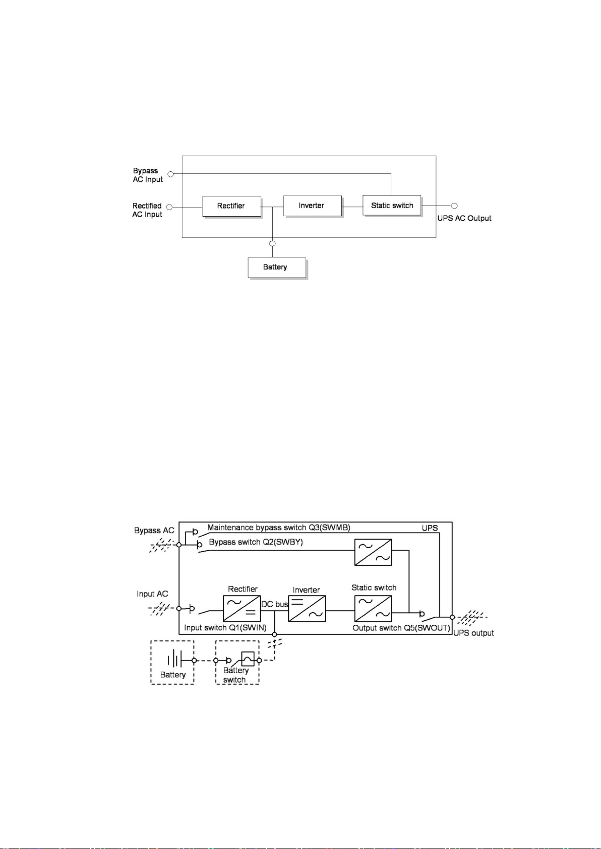
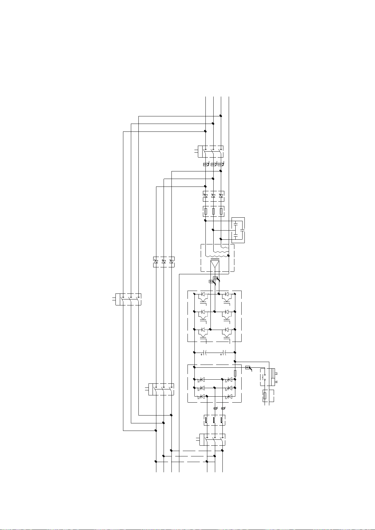
This section introduces the operating principle of the stand-alone UPS. The UPS adopts AC-DC-AC converter (see
Figure 1-1). The first AC-DC conversion adopts three-phase full bridge controlled rectifier to convert the
three-phase AC input power into the steady DC bus voltage.
Figure 1-1 Working Principle of the Stand-alone UPS
The rectifier can also be used as a charger. The inverter takes IGBT half-wave circuit as its inversion topology. The
advanced Space Vector Pulse Width Modulation (SVPWM) is used to control the system, which inverts the DC bus
voltage into AC voltage output.
When the AC is normal, the rectifier and the inverter work at the same time and simultaneously charge the battery.
In case of abnormal AC, the rectifier stops working and the battery supplies power via the inverter. If the battery
voltage drops below the cutoff voltage and the AC is not yet back to normal, the UPS shuts down (If the major
circuit and the bypass circuit are not of the same source and the bypass circuit is normal, the system is powered by
the bypass circuit). The cutoff voltage is preset (eg. the factory setting is 1.67V and the battery cutoff voltage is
320Vdc).
In case of abnormal AC, the battery powers the UPS until its voltage drops to the cutoff voltage. This period of time
is called the ―backup time‖, the length of which depends on the battery’s capacity and the loads.
1.2.2 Bypass Circuit
1. With the intelligent control for the ―static switch‖ which consist of the controlled electronic switching circuit(see
Figure 1-2). The loads can be powered by both the inverter output and the bypass input. Under normal
conditions, the loads are powered by the inverter whose static switch is closed. In case of overload (beyond
the overload time limit) or fault with the inverter, the static switch will automatically switch to the bypass circuit.
Figure 1-2 UPS switch
In normal conditions, complete synchronization of the inverter output and bypass power is a must for achieving
uninterrupted switch between inverter output and bypass power.
Given such requirement, when the bypass power frequency is within the locking range, the inverter output
frequency in the inverter-controlled circuit is tracking the bypass power frequency.
What’s more, there is also a manual maintenance bypass switch in the UPS system. When the UPS needs to be
shut down for maintenance, the bypass power will directly supply power the important loads via the manual
maintenance switch.
Note: When the loads are powered by bypass or maintenance bypass circuit, the power supply is not guaranteed.
U
V
W
N
Inductor
Inverter
fuse
(normal open)
(normal open)
(normal open)
(normal open)
Bat.-
1 4
Bat.+
STS-INV
STS-BY
1
24
1
Aux.switch
control
DC24V
Bat. external
Bat.fuse
Bat.
contactor
21
21
2
1
Output
SWOUT
SWMB
1
2
Aux.switch
1
2
Aux.switch
1
2
Aux.switch
1
2
Aux.switch
R
S
T
N
T
S
R
21
2
1
Mains
input
Rectifier
Inverter
Transformer
SWIN
Output
cap.
R S T
R
S
T
G2R
K2R
1
BUS+
G1R
K1R
G2S
K2S
G1S
K1S
G2T
K2T
G1T
K1T
bus.fuse
Bypass
input
BUS-
4
41
SWBY
(normal open)
1.2.3 System Control Principle
The system control chart is as Figure1-3:
Figure 1-3 UPS system control chart

Normal operation
警告
危险
WARNING
If the UPS system consists more than two UPS standalone machines connected in parallel, do not use the internal
maintenance bypass switch.
Attention: If the input power supply does not have an automatic circuit breaker, the output bus bar and the input
bus bar of the closed UPS standalone machine are dangerous for high voltage.
UPS input AC is normal, the rectifier and the inverter are functioning properly, the loads are powered by the inverter.
And battery switch closed, the battery is under the steady floating charge by the DC bus bar voltage.
(“1+N” parallel UPS system) Note: As the output of all the UPS stand-alone machines are connected in parallel,
the system will check whether all the inverter-controlled circuits are operating synchronously, and whether the
frequency and phase are in consistence with those of the bypass circuit. The output of each circuit should stay the
same. The current for the loads is evenly supplied by each UPS stand-alone machine. In the course of
synchronization, the UPS system will display corresponding warning message.
Only when the above requirements are met will the static switch of the stand-alone machine is closed.
Abnormal AC
In case of AC power failure or abnormality, the rectifier will automatically stop working, and the system will switch to
battery inverter output, the backup time depends on the loads and the battery capacity. If the AC is still not back to
normal during this period of time, the inverter will automatically stop working, and the UPS operating control panel
will display corresponding warning message.
The interruption and recovery of the AC do not disrupt power supply to the loads.
AC Recovery
If the AC recovers within certain time, the rectifier will automatically start (and its output power gradually increases),
supply power to the loads and charge the battery, hence no interruption in the power supply.
Disconnecting Battery
In case of a need to detach the battery from the UPS system for maintenance, the external disconnector can be
used. At this moment, except the battery backup function during AC power failure, all the other functions of the UPS
and the required steady-state performance indexes are not affected.
Failure with UPS Stand-alone Machine
In case of failure with the inverter, the loads will be automatically powered by the bypass circuit, hence no
interruption in output power. Under such condition, please contact the customer service center for technical support.
(“1+N” UPS parallel system) In case of failure with certain standalone machine in the parallel system, this
machine will quit the parallel system. If the machines left can provide sufficient power to the loads, the system will
continue with the power supply, hence no interruption. If the machines left cannot provide sufficient power, the
system will switch to the bypass AC for power supply.
Overload
In case of overload with the inverter which goes beyond the required time limit or current range (see table 8-6), the
inverter will shut down and the system will automatically switch to the bypass circuit for power supply without
interruption. In case the overload falls within the time limit and current range, and when the parallel system can
provide sufficient power supply, the system will switch to the inverter for power supply. In case of short circuit, the
loads switch to the bypass and the inverter will shut down. The switch is first of all decided by the characters of the
protective device used in the system.
For the above two circumstances, the UPS operating control panel displays warning messages.
(“1+N” UPS parallel system) The control logic system continuously monitors the power requirement of the loads
and controls each UPS standalone machine. If the overload time exceeds the set value and the system cannot
provide the loads with sufficient power, the loads will switch to the bypass power. When the load value drops to the
point where the system can provide sufficient power, the system will switch to the inverter for power supply.
Maintenance Bypass Circuit
There is another bypass circuit for the UPS system, i.e. the maintenance bypass circuit, which is used to provide a
safe working environment for the technical staff when they are carrying out regular maintenance or repair for the
UPS system, and also to provide AC power for untreated loads. The maintenance bypass circuit can be manually
selected via the bypass circuit switch, and cut off when switched to ―OFF‖.

1.2.4 ECO Mode (only suitable for the UPS standalone machines)
警告
危险
WARNING
Under the ECO mode, there is no AC voltage distortion protection for the loads.
Under the ECO mode, the loads are primarily powered by the AC bypass circuit while the inverter is in the bypass
state. When the AC exceeds the standard frequency and voltage range (which can be set), the system will switch to
the inverter for power supply.
The ECO mode can be set in the operating control panel.
The operating method of the ECO mode is the same as the description in Chapter 5 UPS Operation Instruction.
Under normal conditions, the loads are powered by the bypass AC. At this time, the inverter power supply indicator
is off and the warning shows ―bypass power supply‖.
1.2.5 UPS Power Switch Setting
Figure 1-2 is a block chart of the UPS standalone machine with ―separated bypass power‖. In the separated bypass,
the static bypass circuit and the maintenance bypass circuit both have an independent bypass power. Without a
separated bypass power, make a short circuit between the input of the bypass switch Q2 and the input of the
bypass switch Q1 (for standard machines, there is expected to be a short circuit here) so that the bypass input and
the rectifier input use the same AC.
When the UPS is operating properly, all the switches should be closed except the maintenance bypass switch Q3.
1.2.6 System Capacity Expansion
The UPS system can have at most 6 UPS standalone machines connected in parallel. By expanding the capacity, it
is able to supply more power to the loads. Capacity expansion should be set or adjusted on the operating control
panel of each standalone machines.
Attention: Capacity Expansion should only be carried out by professional staff. The capacity of all the standalone
machines should be the same, i.e. the system does not support parallel-connected machines with different
capacities.
1.3. Operation Mode
The UPS systems works in one of the following modes:
AC-inverter Power Supply
Mains being converted to DC by the rectifier and inverted to AC by the inverter, the UPS can provide continuous AC
power to the loads. Meanwhile, the charger (the rectifier) charges the battery via floating charge or equalizing
charge.
Battery
Under the battery mode, the battery, after being inverted by the inverter, provides the loads with backup power. In
case of AC failure, the system will automatically switch to the battery mode, hence no interruption in power supply.
When AC power recovers, the system will switch back to the AC-inverter mode automatically, and power supply to
the loads will not stop.
Automatic Power On
The UPS system offers automatic power on. Specifically, if the AC failure extends too long, the battery discharges
till the cut-off voltage and the inverter shuts down. After the AC recovers, after the preset delay time, the UPS will
automatically start up. This function and the delay time are set by the commissioning engineer.
Bypass
Under this mode, the loads are powered by the static bypass AC, which can be seen as an intermediate power
supply mode when the loads are switching between the inverter power supply and the maintenance bypass power
supply. It is also the working mode under abnormal conditions.
Maintenance Bypass
When the UPS is off, the loads are connected to the bypass power via the maintenance bypass switch.
Joint Power Supply
The UPS system offers joint power supply. AC input power together with battery backup power to meet the demand
of the loads. It is useful in the occasions which high electricity charge during peak hours or in the occasions where

the oil engine cannot meet the power demand of the loads during the AC failure. Joint power supply can be set by
the users, and the share of AC input can be set from 20% to 100%.
ECO Mode (only applicable in the stand-alone system)
All the power switches and battery switches are closed, and the loads are primarily powered by the bypass circuit.
When the bypass power is within the normal frequency and voltage ranges, the loads are powered by the bypass
circuit and the inverter serves as a backup. When beyond the ranges, the system will switch to the inverter output.
Parallel Redundancy (system capacity expansion)
In order to increase system capacity or reliability, or both, you may set the UPS stand-alone machines to be directly
connected in parallel, which ensures even load sharing among all the stand-alone machines through their internal
control logic. The parallel system can have at most 6 stand-alone machines connected together.
Frequency Converter
The UPS has a frequency converter mode which offers 50Hz and 60 Hz firm outputs. The input frequency ranges
between 45Hz and 65Hz. Under this mode, the bypass switch should be cut off, the static bypass circuit is invalid,
and the battery is optional in light of whether there is a need to operate in the battery mode.
警告
危险
WARNING
Before the commissioning engineer powers on the UPS for debugging, make sure to keep the dust cover on top of
the UPS to prevent accumulation of dust in the machine which may result in system failure and safety hazards.
警告
危险
WARNING
Do not power on the UPS before the commissioning engineer comes.
警告
危险
WARNING
The installation of the UPS should be carried out according to instructions in the manual by professional engineers.
For issues that are not mentioned in the manual. Please refer to the detailed mechanical and electrical installation
materials as supplement enclosed in the products.
警告
危险
WARNING: Battery is Dangerous
Installing the battery requires enormous carefulness. When the battery is connected, its terminal voltage exceedes
400Vdc, which may lead to electric shock.
1. Please wear eye shield to prevent harm from electric arcs.
2. Please take off your metal accessories like ring, watch and things alike.
3. Use tools with insulated handles.
4. Wear rubber gloves.
5. In case of leakage of the battery electrolyte or damage, the battery must be replaced. Put the discarded battery
in an anti-acid container and scrap it according to relevant requirements.
6. If the electrolyte drops on the skin, wash it immediately.
警告
危险
WARNING
The UPS system can be connected to the neutral and ungrounded power system (i.e. IT system).
2. Mechanical Installation
This chapter briefly introduces the mechanical installation of the UPS, including the do’s and don’ts, environment
requirements, mechanical requirements, initial check before installation and installation diagram.
2.1 The Do’s and Don’ts
This chapter introduces the environment and mechanical requirements for the siting and wiring of the UPS system.
Due to the distinctive characteristics of each locale, this chapter does not introduce the detailed installation
procedure, but rather offers a general installation procedure and method to the installation staff who may make
specific treatments according to the conditions of the locale.
2.2 Environment Requirements
2.2.1 Site Selection for the UPS
The UPS should be installed in a cool, dry, clean and well-ventilated environment. The dust should not have
conductive powder (like metal powder, sulfide, sulfur dioxide, graphite, carbon fiber, conductive fiber etc.), acid mist
or other conducting medium (dense ionized materials). Specific environment indicators should meet national
standards and regulations, as well as the requirements of this manual. (See table 8-2)

警告
危险
WARNING
The hoisting equipment must have sufficient ability to lift the UPS cabinets.
Forced air cooling is provided by the internal fan. The cool air enters the UPS via the air grids of the UPS machine
and exhaust through the top of the UPS. If the UPS is installed on the raised floor, with wires connected at the
bottom, the cool air may also enter the UPS via the gaps of the floor. Exhaust fan recommended to be installed if
necessary to accelerate ventilation in the environment. In an environment where there is much dust, an air filter is
needed.
Note1: When the battery is installed near the UPS, the upper limit of room temperature is decided by the battery,
not the UPS.
Note2: Under the ECO mode, the power consumption is relatively small. Under the mode of inverter power supply,
the power consumption is quite big, which requires appropriate air conditioning.
2.2.2 Site Selection for the Battery
Temperature is a major factor for the battery capacity and service life. The standard room temperature for the
battery is 20℃, above which the service life might be undermined and below which the battery capacity is reduced.
Under normal conditions, acceptable room temperature is between 15℃ and 25℃. The room temperature should
remain constant and the battery should be kept away from heat or major vents.
The battery recommended to be installed in the battery cupboard close to the UPS. If the battery is placed on the
raised floor, just like the UPS, a holder is required to be put below the floor. If the battery is placed in the battery
shelf or other places away from the UPS, the battery switch should be installed as close to the battery as possible
to ensure the shortest wiring.
2.3 Mechanical Requirements
2.31 System Configuration
According to the different design requirements, a UPS system may consist of several equipment cabinets, for
example UPS cabinet and battery cabinet. In normal circumstances, all the cabinets are installed abreast of the
same height to make them neat.
2.32 Moving the Cabinets
Make sure the weight of the UPS is within the loading capacity of the hoisting equipment. See Table 8-3 for the
weight of UPS.
The UPS cabinets can be carried by the forklift. Before loaded onto the forklift, remove the grid plates at the bottom,
front (or side) of cabinets.
If the forklift is not available, use the rollers.
2.33 Operation Space
There is no fan at both sides of the UPS, hence no special requirement for the space. Please leave a space of
1,000mm for the sake of maintenance operation over the magnetic components at the back. Sufficient room should
be left in front of the UPS so that people may freely walk past the UPS with front door open vertically.
2.34 Wiring
The UPS adopts bottom wiring. It is suggested to choose appropriate cable route and proper wiring to ensure that
the cables can be smoothly connected to the UPS line bank.
2.4 Initial Check
Before installing the UPS, check the following items:

1. Make sure that the room environment meets the requirements of the product technical specifications,
particularly the temperature, ventilation and dust.
2. Unpack the UPS and the battery and have a visual inspection over whether there is any damage within and
outside the UPS and the battery. If so, contact the common carrier.
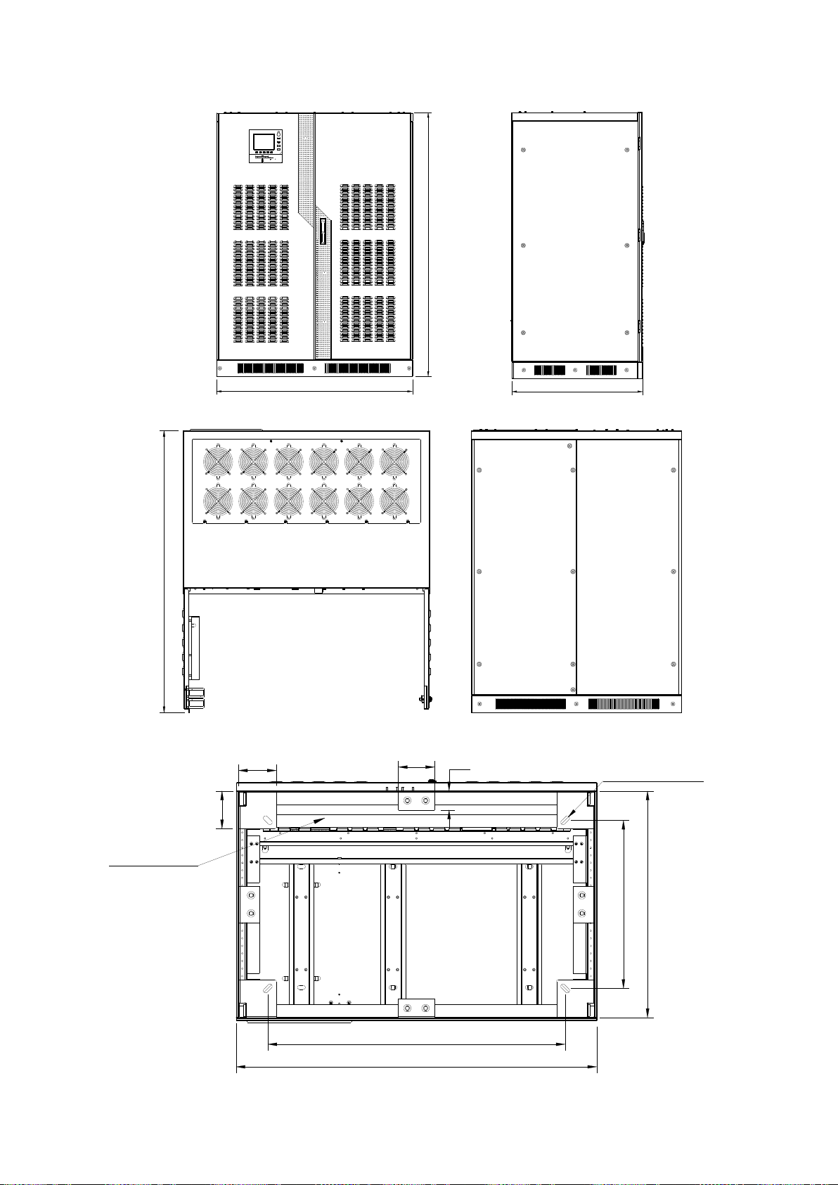
2.5 Installation Diagram
This section introduces the key mechanical characteristics of the UPS cabinets.
STATUS
OUTPUTINVERTER
BAT.
BYPASS
RECTIFIER
EPO
INVERTER ON
INVERTER OFF
FAULT CLEAR
F1 F2 F3 F4 HELP
SILENCE
ON/OFF
1190
1602
789
1363
557
750
982
1191
125
125
4-? 15×35
120
63
Entrance
Front View Side View
Top View Rear View
Figure 2-7 160kVA/200kVA UPS (6 pulse rectifier) front/side/top/rear view (mm)
Figure 2-8 160kVA/200kVA UPS (6 pulse rectifier) bottom view (mm)
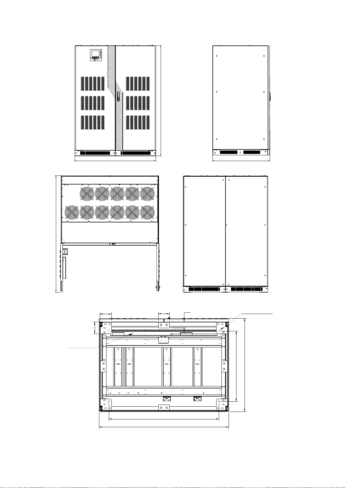
1393
1906
STATUS
OUTPUTINVERTER
BAT.
BYPASS
RECTIFIER
EPO
INVERTER ON
INVERTER OFF
FAULT CLEAR
F1 F2 F3 F4 HELP
SILENCE
ON/OFF
1000
1663
757
4-? 15×35
1393
1182
125
125
120
63
1000
Entrance
Front View Side View
Top View Rear View
Figure 2-9
250kVA/300kVA/400kVA UPS (6 pulse rectifier) front/side/top/rear view (mm)
Figure 2-10 250kVA/300kVA/400kVA UPS (6 pulse rectifier) bottom view (mm)

警告
危险
Warning
Before wiring, please double check the switch on the upstream panel connected to the mains input /bypass input
/battery input of UPS. Make sure that the switch is off and attach a warning signal to prevent others from turning on
the switch.
3.Electrical Installation
This chapter mainly introduces the electrical installation of the UPS, including the procedure and method for
connecting the power cable and the control cable, as well as the distance between the equipment connection joint
and the floor.
After the mechanical installation of the UPS, it is time to connect the power cables and the control cables. All the
control cables, shielded or not, should have separate routing different from the power cables in the metal tubes
which are joined with the metal parts of the cabinets.
3.1 Wiring of Power Cables
Please refer to 2.3.4 Wring Method for cable wiring.
3.11 System Configuration
The wire diameter for the system’s power cables should meet the following requirements:
UPS Input Cable
The wire diameter for the UPS input cables varies in light of the UPS power and input AC voltage and should meet
the maximum input current requirement, including the maximum battery charging current. See Table 3-1.
UPS Bypass and Output Cable
The wire diameter for the UPS varies in light of the UPS capacity and input voltage level and should meet the
maximum input current requirement (max. charging current). See Table 3-1.
Battery Cable
Each UPS is connected with the battery via the positive and negative poles. The wire size for the battery cables
depends on the UPS capacity and should meet the max. battery discharge current requirements when the battery
voltage is close to the cut-off one. See Table 3-1.
3.12 Cable Specification
The specification for UPS with different powers is listed in Table 3-1.
UPS
power
(kVA)
Rated Current: Amps
Specifications for the stud bolt of the
busbar
Input AC when the battery
is full loaded
Full loaded output
Battery discharging
current at the lowest
battery voltage
(400Vac)*
Input/output
cable
Battery
cable
Moment of
force(Nm)
380V
400V
415V
380V
400V
415V
bolt
Copper
bar
160
341
324
312
243
231
222
464
M8
Ф9
M8 bolt
12~15
200
426
405
390
304
289
278
580
M8
Ф9
M8 bolt
12~15
250
533
506
488
380
361
348
725
M10
Ф11
M10 bolt
25~30
300
639
608
585
456
434
417
870
M10
Ф11
M10 bolt
25~30
400
852
810
780
608
578
556
1160
M10
Ф11
M10 bolt
25~30
Note*: For the 380Vac power input, the maximum battery discharging current increases by 3%;for the 415Vac input, the
maximum battery discharging current decreases by 3%.
警告
危险
Warning
If ground connection is not done as required, it may lead to electric shock and fire risk.
Table 3-1 UPS Power Cable Specifications
3.13 The Do’s and Don’ts
The following points only offer general guidance. If there are local standards, follow the local standards.
1. The wire diameter for neutral line should be chosen based on 1.5 times of the output/bypass phase current.
2. The wire diameter for the protective ground wire should be chosen based on 2 times of the output/bypass
conductor (which depends on the fault level, cable length and protection type etc.).
3. For cables with big current, thinner cables connected in parallel can be used, which may facilitate installation.
4. When choosing the wire diameter for the battery cables, refer to the current value in Table 3-1 and a voltage
drop of 3Vdc is allowed.
5. For most installation, particularly the installation of a system with multiple stand-alone machines connected in
parallel, the loading equipment is connected with the bus bar power distribution network powered by the UPS,
instead of directly connected with the UPS. Under such circumstances, the wire diameter for the UPS output
cables should meet the requirements of the output power distribution network, rather than depending on the full
load conditions of the stand-alone machines.
3.14 Cable Connector
The rectifier input, bypass, output and battery power cables are connected with the bus bar under the power switch.
See Figure 3-2~Figure 3-6.
3.15 Protected Area
There is ground connection near the input and output copper bar, as is shown in Figure 3-2~Figure 3-6. The
protective ground wire should be plugged into the ground connection and connected with each cabinet in the
system.
All the cabinets and cable troughs should have ground connection according to local requirements. The ground wire
should have wire turn secured over a metal bridge to prevent the fastening bolt from loosening when being pulled.
3.16 Protector
Out of concern for safety, it is necessary to install a breaker outside the UPS for the input power and battery. As the
specific installation conditions vary, the section only offers general information for the installers, including basic
knowledge about the operation practice, rules and regulations, equipment installation etc.
Rectifier and Bypass Input Power
1. Input current and short circuit protection
 Loading...