

Page 1

BrightEye NXT 410, 410-H, 415 & 430
Compact Routers
3G/HD/SD/HDMI
Installation, Conguration and
Operations Guide
Revision 1.2 SW v2.0.0
Page 2
Clearly, Ensemble wants to be in the broadcast equipment business. It’s so rare anymore to nd a company of this
caliber that has not been gobbled up by a large corporation. They are privately held so they don’t have to please the
money people. They really put their eorts into building products and working with customers.
I’m really happy with the BrightEye products and Ensemble’s service, and even more important my engineers are
happy. We’ve continued to upgrade the product and add more cards. We will be rebuilding our production control
room and we will use BrightEye again.
~ Don McKay, Vice President Engineering, Oregon Public Broadcasting
Who is Ensemble Designs?
By Engineers, For Engineers
In 1989, a former television station engineer who loved
designing and building video equipment, decided to
start a new company. He relished the idea of taking
an existing group of equipment and adding a few
special pieces in order to create an even more elegant
BrightEye frames handle 270
Mb/s, 1.5 Gb/s and 3 Gb/s signals,
audio and MPEG signals. Used
worldwide in broadcast, mobile,
production, and post.
ensemble. So, he designed and built his first product and
the company was born.
Focused On What You Need
As the company has grown, more former TV station
engineers have joined Ensemble Designs and this wealth
of practical experience fuels the company’s innovation.
Everyone at the company is focused on providing the
We’re focused on
processing gear–
3G/HD/SD/ASI video,
audio and optical units.
very equipment you need to complete your ensemble
of video and audio gear. We offer those special pieces
that tie everything together so that when combined, the
whole ensemble is exactly what you need.
Notably Great Service for You
We listen to you – just tell us what you need and we’ll
do our best to build it. We are completely focused on
you and the equipment you need. Being privately held
means we don’t have to worry about a big board of
directors or anything else that might take attention away
from real business. And, you can be sure that when you
call a real person will answer the phone. We love this
business and we’re here to stay.
Bricks and Mortar of Your Facility
The bricks and mortar of a facility include pieces like
up/downconverters, audio embedders, video converters,
routers, protection switches and SPGs for SD, HD and
3 Gb/s. That’s what we’re focused on, that’s all we do
– we make proven and reliable signal processing and
infrastructure gear for broadcasters worldwide, for you.
Come on by and visit us.
Drop in for lunch and a tour!
Shipped with care to
television broadcasters
and video facilities all
over the world.
Page 3

BrightEye NXT 410/415/430 Compact Router Installation, Configuration and Operations Guide
Contents
Preface 11
Document Organization at a Glance 11
Chapter 1: Introduction 12
In this Chapter 12
Purpose of Document 12
Intended Audience 12
Introductory Videos 13
Additional Resources 14
Chapter 2: System Overview 15
In this Chapter 15
Features 15
Clean Switching between Asynchronous Sources 16
Assignable I/O and Flexible Architecture 16
Signal Diagnostics 16
Ethernet Connectivity and Long Distances 16
Front Panel Controls 17
Rear Connectors 18
BrightEye NXT 410 and 410-H Clean HDMI Compact Routers 18
BrightEye NXT 415 and 430 Compact Routers 19
Default Port Configuration as Shipped from the Factory 20
410 and 410-H Default Port Conguration 20
415 and 430 Default Port Conguration 20
Applications 21
Cuts-Only Master Control 21
Quality Control and Signal Monitoring 22
Multi-Stage Venue 22
Monitors and Projectors for Venues 23
www.ensembledesigns.com Page 3
Page 4

BrightEye NXT 410/415/430 Compact Router Installation, Configuration and Operations Guide
Chapter 3: Installation 24
In this Chapter 24
Connecting Cables to Ports 24
Connecting a Reference If Needed 24
Connecting the Power Supply 25
Connecting Ethernet for Web Control Point (Optional) 25
RS-232 Interface Option 25
Chapter 4: Configuration 26
In this Chapter 26
Router Configuration Menus 27
Menus Accessed from the Front Panel 27
Configuration Controls 28
Conguration Button 28
Navigation Buttons 28
Information Button 28
Front Panel Navigation 28
Menus Accessed from the Web Interface 29
Assigning Shortcut Buttons 30
About Port Configuration 31
Planning Router Port Configuration 31
Cabling Router and Configuring Ports to Match Plan 31
Definitions of Port Configuration Choices 31
Unassigned 31
Source 31
Destination 31
Follow 31
Primary TSG 32
Secondary TSG 32
Port Configuration Choices Available According to Port Type 33
For Fixed Input 33
For Fixed Output 33
For Bi-Directional 33
www.ensembledesigns.com Page 4
Page 5

BrightEye NXT 410/415/430 Compact Router Installation, Configuration and Operations Guide
Configuring the Router’s Ports from the Front Panel 34
Assigning Ports 34
To Assign Ports 34
Renaming Ports 34
To Rename a Port 35
Adjusting Audio Levels 35
To Adjust Audio Levels 35
Mapping Audio Channels 36
To Remap Audio Channels 36
Configuring the Router’s Ports from the Web Interface 37
Assigning and Naming Ports 37
To Assign and Name Ports 37
Adjusting Audio Levels 38
To Adjust Audio Levels 38
Mapping Audio Channels 39
To Remap Audio Channels 39
About Clean Switches and Clean Switch Configuration 40
Genlocked to Reference 40
Embedded Audio 40
Output Port Following a Clean Switched Destination 40
Clean Switch Output Timing 40
Imposing Delay on a Video Signal 41
Pre-Selector to a Production Switcher 41
Feeding On-Set Monitors in a Live Environment 41
Configuring Clean Switches from the Front Panel 42
To Assign a Clean Switch to a Destination 42
To Set the Standard for Clean Switches 42
To Set the Output Timing for Clean Switches 43
To Set the Audio Enables for Clean Switches 43
To Set Audio Breakaway 44
Configuring Clean Switches from the Web Interface 45
To Assign a Clean Switch to a Destination 46
To Set the Standard for Clean Switches 46
www.ensembledesigns.com Page 5
Page 6

BrightEye NXT 410/415/430 Compact Router Installation, Configuration and Operations Guide
To Set the Output Timing for Clean Switches 47
To Set the Audio Enables for Clean Switches 47
To Set the Audio Breakaway for Clean Switches 47
Setting Up Timing and Genlock 48
To Select the Reference Source from the Front Panel 48
System Frame Rate 48
Vertical Interval Switch Point 48
To Select the Reference Source from the Web Interface 49
Note on Frame Rates 49
50 Hz 49
59.94 Hz 49
60 Hz 49
Working with the Internal Test Signal Generators 50
Configuring the Internal Test Signal Generators from the Front Panel 50
To Select the TSG Standard 51
To Select the TSG Pattern 51
To Set the TSG Vertical Timing 52
To Set the TSG Horizontal Timing 52
To Congure the TSG Slate 53
To Congure the TSG Slate Text 53
To Congure the TSG Cyclops 54
To Congure the TSG Audio Reference Level 54
To Congure the TSG Audio Enables 55
To Congure the TSG Audio Channels 56
Configuring the Internal Test Signal Generators from the Web Interface 57
Standard 58
Pattern 58
Vertical and Horizontal Timing 59
Audio Embedding 59
Audio Reference Level 60
Audio Group Enable 60
Audio Source Selection 60
Slate On 61
Slate Text 61
Cyclops 61
www.ensembledesigns.com Page 6
Page 7

BrightEye NXT 410/415/430 Compact Router Installation, Configuration and Operations Guide
Setting Up a Web Control Point (Optional) 62
Connecting an Ethernet Cable 62
Assigning the BrightEye NXT a New IP Address and Subnet Mask 62
To Set the IP Address 62
To Set the Subnet Mask 63
Gateway and DNS Server Settings 63
Requesting the Web Control Point 64
Assigning the Default Profile to the Web Control Point 66
Establishing Additional Web Control Points and Access Authentication 68
Characteristics of Control Points 68
Examples of Control Points 68
Configuring Additional Control Points 69
First Method: Requesting Access from a Desired Control Point 69
Second Method: Assigning an IP Address From the Admin Control Point 69
Approving Pending Authorizations 69
Number of Control Points That Can Operate Simultaneously 70
Asymmetrical Bandwidth Requirements 70
Best Practice: Closing Web Browser Control Points When Not In Use 70
Creating and Editing Profiles 71
Characteristics of Profiles 71
Creating an Initial Set of Profiles 71
To Create a Prole 71
Examples of Profiles 72
Master Control Room (MCR) 10 x 2 72
MCR Prole Edited and Reordered to 8 x 2 73
MCR Prole Edited to 8 x 1 74
Setting Up Salvos 75
To Create a Salvo 75
First Method 75
Second Method 76
Security and Administrative Access to Settings 78
To Limit Access to the Router’s Settings 78
www.ensembledesigns.com Page 7
Page 8

BrightEye NXT 410/415/430 Compact Router Installation, Configuration and Operations Guide
Saving and Restoring Configuration Settings 79
To Save Configuration Settings 79
To Upload Configuration Settings 79
Chapter 5: Operations and Step-by-Step Procedures 81
In this Chapter 81
Operations Using the Front Control Panel 81
Making a Cross Point Switch in Preset/Take Panel Mode 81
Selecting a Destination 81
Selecting a Source 81
Pressing Take 82
Performing Direct Takes 82
To Enter Direct Take Panel Mode 82
To Make a Direct Take 82
To Exit Direct Take Panel Mode 82
Performing Mix Takes with the Front Panel 83
Clean Switch Required 83
To Enter Mix Mode 83
To Make a Mix Take 83
To Exit Mix Mode 83
Viewing Information about a Routed Signal 84
Disabling the Front Panel for Safe Driving Mode 84
To Enter Safe Driving Mode 84
Operations Using a Web Control Point 85
Prerequisites 85
Accessing the Web Browser Control Interface 85
Performing Takes 85
To Perform a Take by Selecting a Source and a Destination 85
To Perform a Take by Selecting Only a New Source 85
Performing Direct Takes 86
To Perform a Direct Take 86
To Exit Direct Take Mode 86
Performing Gang Takes 87
To Perform a Gang Take 87
To Exit Gang Mode 87
www.ensembledesigns.com Page 8
Page 9

BrightEye NXT 410/415/430 Compact Router Installation, Configuration and Operations Guide
Performing Direct Gang Takes 87
To Perform a Direct Gang Take 87
To Exit Direct Gang Mode 87
Performing Mix Takes 88
Clean Switch Required 88
To Perform a Mix Take 88
Keyboard Shortcuts for the Web Interface 89
Selecting Sources 89
Selecting Destinations 89
Performing a Take 89
Performing a Mix 89
Performing a Direct Take 89
Gang Selections 89
Using Salvos 90
To Perform a Salvo 90
Salvo Keyboard Shortcuts 90
Display Preferences 91
Chapter 6: External Control 92
The BrightEye NXT’s Approach to Control Integration 92
RS-232 Interface Option 92
9-Pin D Connector Pin Out 92
Supported Control Protocols Overview 92
Software Development Kit (SDK) 93
Accessing Features Unique to the BrightEye NXT Compact Routers 93
Configuring External Control 94
Automation Protocols 95
Introduction 95
Conventions 95
Overview 96
Before You Begin 96
Understanding Profiles 97
Configuration 99
Prole Conguration 100
External Control Conguration 100
www.ensembledesigns.com Page 9
Page 10

Protocols 101
GV TEN-XL ASCII Protocol 101
GV Performer ASCII Protocol 105
Generic ASCII Protocol 110
Chapter 7: Maintenance and Troubleshooting 118
Switching Signals Does Not Occur Smoothly 118
Cannot Connect to the BrightEye NXT from a Web Browser 118
Supported Browsers 118
The Take Button is Grayed Out 119
Resetting to Factory Default Settings 119
Software Updating 119
Warranty and Factory Service 120
Warranty 120
Factory Service 120
Specifications 121
For BrightEye NXT 410 Clean HDMI Router 121
For BrightEye NXT 415 and 430 Compact Routers 122
Glossary 123
Page 11
BrightEye NXT 410/415/430 Compact Router Installation, Configuration and Operations Guide
Preface
Document Organization at a Glance
This manual addresses all of the essential topics for understanding how to install, configure and use
the BrightEye NXT 410, 410-H, 415 and 430 Compact Routers. See the following table for a quick
glance at what each chapter addresses. Note that the items in the main table of contents, as well as the
chapter titles below, are links.
Chapter Title Topics Covered
Chapter 1: Introduction A brief introduction to this document and to the BrightEye NXT Router
with links to additional resources such as training videos.
Chapter 2: System
Overview
Chapter 3: Installation This chapter describes the cable connections needed.
Chapter 4: Configuration Addresses configuration menus for the front panel and the web
Chapter 5: Operations and
Step-by-Step Procedures
Chapter 6: External Control Addresses how the BrightEye NXT handles external control integration;
Chapter 7: Maintenance
and Troubleshooting
Specifications Presents standard specifications for the BrightEye NXT Router
Glossary Includes definitions of commonly-used terms relevant to the video
Describes the overall BrightEye NXT Router system—its hardware and
software components and example applications.
interface; assigning shortcut buttons; configuring ports; working with
clean switches; audio level adjustments; audio channel mapping;
setting up timing and genlock; configuring internal test signal
generators; setting up a web control point (optional); establishing
additional web control points and access authentication; creating and
editing profiles; downloading and uploading configuration settings;
and security and administrative access to settings.
After the BrightEye NXT Router has been installed and configured, it
is ready to use. This chapter addresses all of the standard operational
tasks of the BrightEye NXT Router that you can perform using the
front panel and web browser interface. Operational tasks include
performing takes, direct takes, mix takes, gang takes, direct gang takes,
and accessing ancillary data.
supported control protocols; SNMP Interface; RS-232 interface option.
This chapter addresses possible issues that new users may encounter
while becoming familiar with the BrightEye NXT Router.
regarding inputs, max cable length, outputs and reference.
broadcast industry.
www.ensembledesigns.com Page 11
Page 12

BrightEye NXT 410/415/430 Compact Router Installation, Configuration and Operations Guide
Chapter 1: Introduction
In this Chapter
This chapter addresses the following topics:
• Purpose of Document
• Intended Audience
• Introductory Videos
• Additional Resources
Purpose of Document
This Installation, Configuration and Operations Guide supports the process of planning for, installing,
configuring and operating the Ensemble Designs BrightEye NXT 410, 415 and 430 Compact Routers.
This manual describes the elements of the system, how they work together, and the practical aspects
of working with the Router to meet your facility’s needs.
Use the Contents and the Preface to quickly link to a specific chapter or topic.
Intended Audience
In addition to the target audience listed below, this document is meant for anyone who needs to
target a specific area of functionality in order to meet an immediate need, as well as for those who
need to have a comprehensive understanding of the Router from a systems planning point of view.
The intended audience for this manual includes people with the following roles:
• studio designers
• broadcast engineers
• installation and configuration personnel
• router operators
www.ensembledesigns.com Page 12
Page 13
BrightEye NXT 410/415/430 Compact Router Installation, Configuration and Operations Guide
Introductory Videos
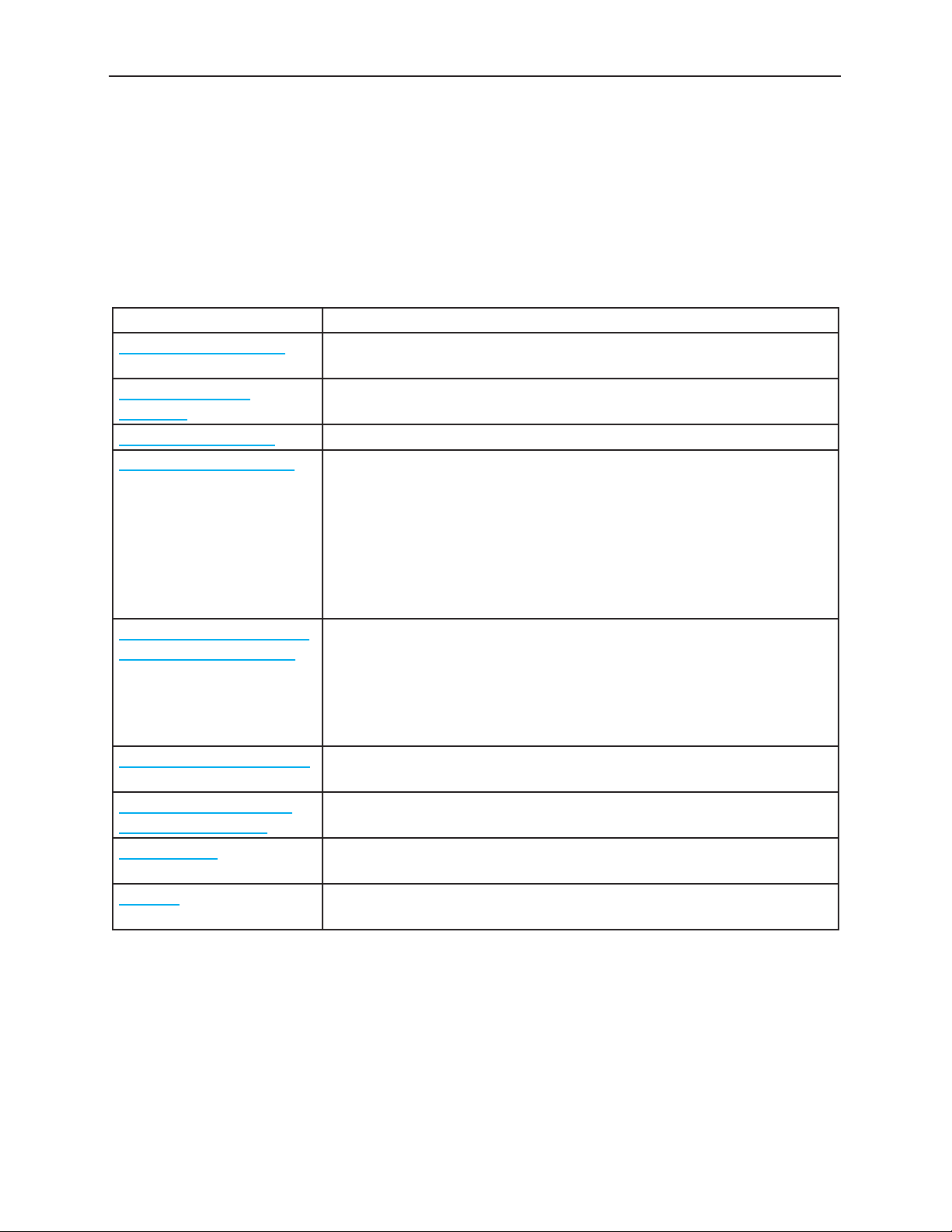
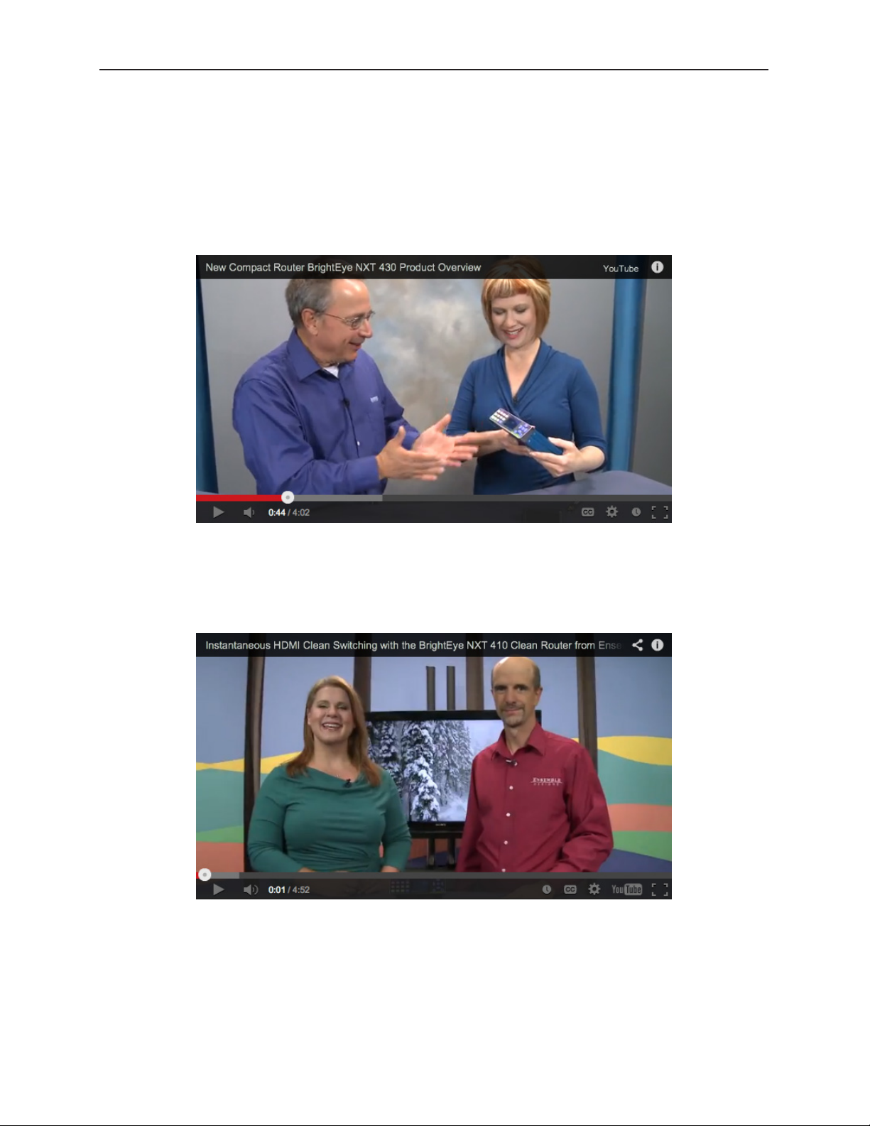
The BrightEye NXT products can be configured with various options and in different sizes to address a
wide variety of applications. Please view the two brief videos below for an overview of the BrightEye
NXT 430 Compact Router by Technology Evangelist John Pichitino and Marketing Czar Cindy
Zuelsdorf, and the BrightEye NXT 410 Clean HDMI Router by Director of Sales Mondae Hott and
Engineer Chris Merrick.
John Pichitino and Cindy Zuelsdorf talking about the new BrightEye NXT 430
Compact Router. Note that the photograph is a link to a video on the
Ensemble Designs website.
Mondae Hott and Chris Merrick talking about the new BrightEye NXT 410
Clean HDMI Router. Note that the photograph is a link to a video on the
Ensemble Designs website.
www.ensembledesigns.com Page 13
Page 14

BrightEye NXT 410/415/430 Compact Router Installation, Configuration and Operations Guide
Additional Resources
In addition to this document, please refer to these resources:
• BrightEye NXT Routers Quick Start Guide
• BrightEye NXT Training Videos
• BrightEye NXT 430 Compact Router Demo at NAB 2014
• BrightEye NXT Router Family Brochure
• BrightEye NXT 430 and NXT 415 Compact Routers product page from the Ensemble Designs
web site
• BrightEye NXT 410 Clean HDMI Router product page from the Ensemble Designs web site
www.ensembledesigns.com Page 14
Page 15

BrightEye NXT 410/415/430 Compact Router Installation, Configuration and Operations Guide
Chapter 2: System Overview
In this Chapter
This chapter addresses the following topics:
• Features
• Clean Switching between Asynchronous Sources
• Assignable I/O and Flexible Architecture
• Signal Diagnostics
• Ethernet Connectivity and Long Distances
• Front Panel Controls
• Rear Connectors
• Applications
Features
• Routing for 3G, HD, SD video (410 also works with HDMI)
• LCD display with realtime full motion video (can be disabled for safe driving mode for cars)
• Flexible I/O. Independently assign BNCs and SFPs as Inputs or Outputs
• Clean Switching of video and embedded audio (410 and 430)
• Passes embedded audio
• Audio level adjustments on a per input source and per channel basis when the signal is output
through a Clean Switch
• Mix and Direct Take modes
• Two built-in Test Signal Generators
• Front Panel and Web-Based Control
• Genlockable and Timeable
• Eight Salvo Registers, includes the choice of Cut or Mix transition and transition duration
• Ability to Save/Restore the entire configuration of the product as a data file on a computer. Use
to replicate the same overall configuration to multiple NXT routers
• TCP/IP Interface for Networking and Control
• RS-232 Interface Option
• Compact and Rugged
• 5-Year Warranty and Free Software Upgrades
www.ensembledesigns.com Page 15
Page 16

BrightEye NXT 410/415/430 Compact Router Installation, Configuration and Operations Guide
Clean Switching between Asynchronous Sources
The BrightEye NXT 410 Clean HDMI Router and the BrightEye NXT 430 Clean Router provide clean,
quiet switching of video and audio sources. Both units have two clean switched outputs, providing full
frame synchronization.
Assignable I/O and Flexible Architecture
The BrightEye NXT 415 and BrightEye NXT 430 have 2 fixed input BNCs, 2 fixed output BNCs and 7
independently assignable BNCs that can be configured as inputs or outputs. The two SFP (small format
pluggable) cages can be populated with dual SFPs that have fiber optic or other connectors.
The BrightEye NXT 410 has 2 fixed input BNCs, 2 fixed output BNCs, and 1 assignable BNC that can be
configured as an input or an output. There are also 4 fixed input HDMI ports, 1 fixed output HDMI port,
and 1 SFP cage that can be populated with dual SFPs.
Signal Diagnostics
Circuitry on every BrightEye NXT unit detects and measures key parameters associated with each
video source, such as synchronicity and timing, line and frame rate, embedded audio presence or
absence, closed caption information, and timecode data. These parameters can be displayed on both
the front panel LCD screen and on web interface control points.
Ethernet Connectivity and Long Distances
Because the web interface connects to the BrightEye NXT Router over Ethernet, and because Ethernet
reaches much farther than coaxial cable, BrightEye NXT Router web interface control points can be
physically located very far away from the BrightEye NXT Router if desired.
For example, if you need the capability to select sources at the transmitter remotely, such as in the
event of either a master control switcher failure or a microwave link failure between the studio and
the transmitter, you can use the BrightEye NXT Router as part of a backup switcher at the transmitter.
Sources such as a network feed, a small server or a weather camera could be switched to air in an
emergency.
www.ensembledesigns.com Page 16
Page 17
BrightEye NXT 410/415/430 Compact Router Installation, Configuration and Operations Guide
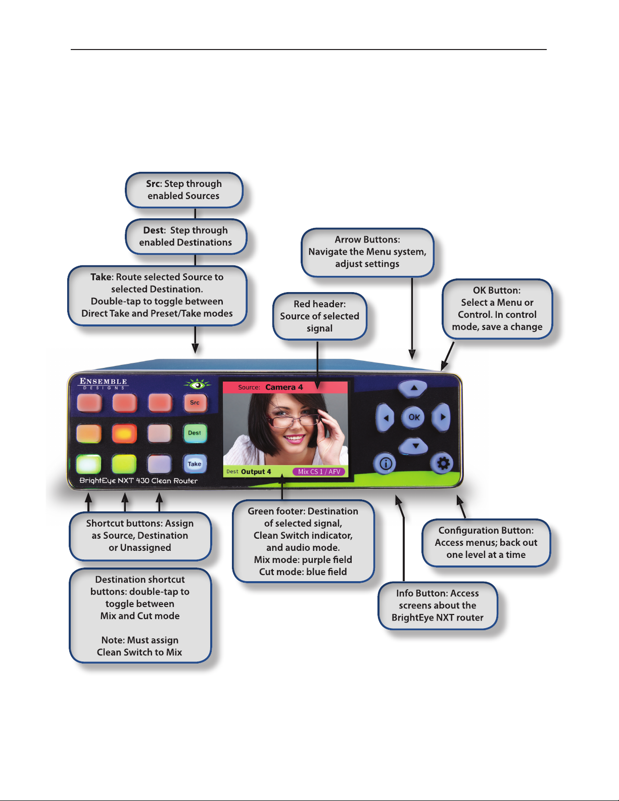
Front Panel Controls
All three models of the Router—the BrightEye NXT 410 Clean HDMI Router, the BrightEye NXT 415
Router and the BrightEye NXT 430 Clean Router—share the same front panel shown below.
www.ensembledesigns.com Page 17
Page 18
BrightEye NXT 410/415/430 Compact Router Installation, Configuration and Operations Guide
Rear Connectors
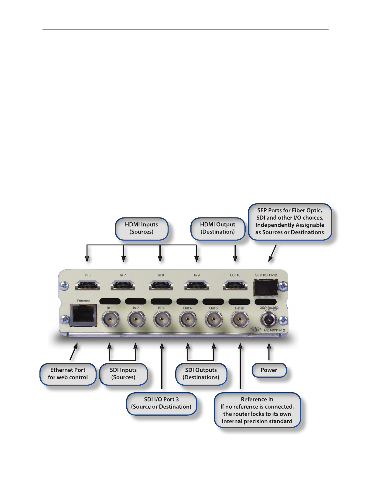
BrightEye NXT 410 and 410-H Clean HDMI Compact Routers
The BrightEye NXT 410 Clean HDMI Router provides clean, quiet switching of HDMI and SDI video and
audio sources. Model 410-H accepts HDCP-encrypted content. The front panel LCD displays realtime
full motion video of your router sources. Feed the BrightEye NXT 410 with cameras and other HDMI
sources and take the output to projectors, flat screens and production equipment. The built-in frame
synchronizer provides two assignable clean switched outputs. Perform dissolves and direct takes
from the front panel, or with the web browser interface using a computer, tablet or smartphone.
Audio breakaway, audio level adjustments, and audio channel mapping offer routing flexibility in live
applications. Save the entire configuration of the NXT as a data file. Upload saved settings to replicate
the same overall configuration to multiple NXT routers.
With both HDMI and SDI inputs and outputs, you can integrate and switch signals from all types of
equipment, regardless of the video format. Cameras with HDMI outputs can be used directly alongside
SDI sources, and routed to either HDMI or SDI outputs. The SFP (small format plugable) cage can be
populated with dual SFPs that have fiber optic or other connectors, providing the ability to combine
electrical BNC, HDMI and fiber optic inputs and outputs.
www.ensembledesigns.com Page 18
Page 19
BrightEye NXT 410/415/430 Compact Router Installation, Configuration and Operations Guide
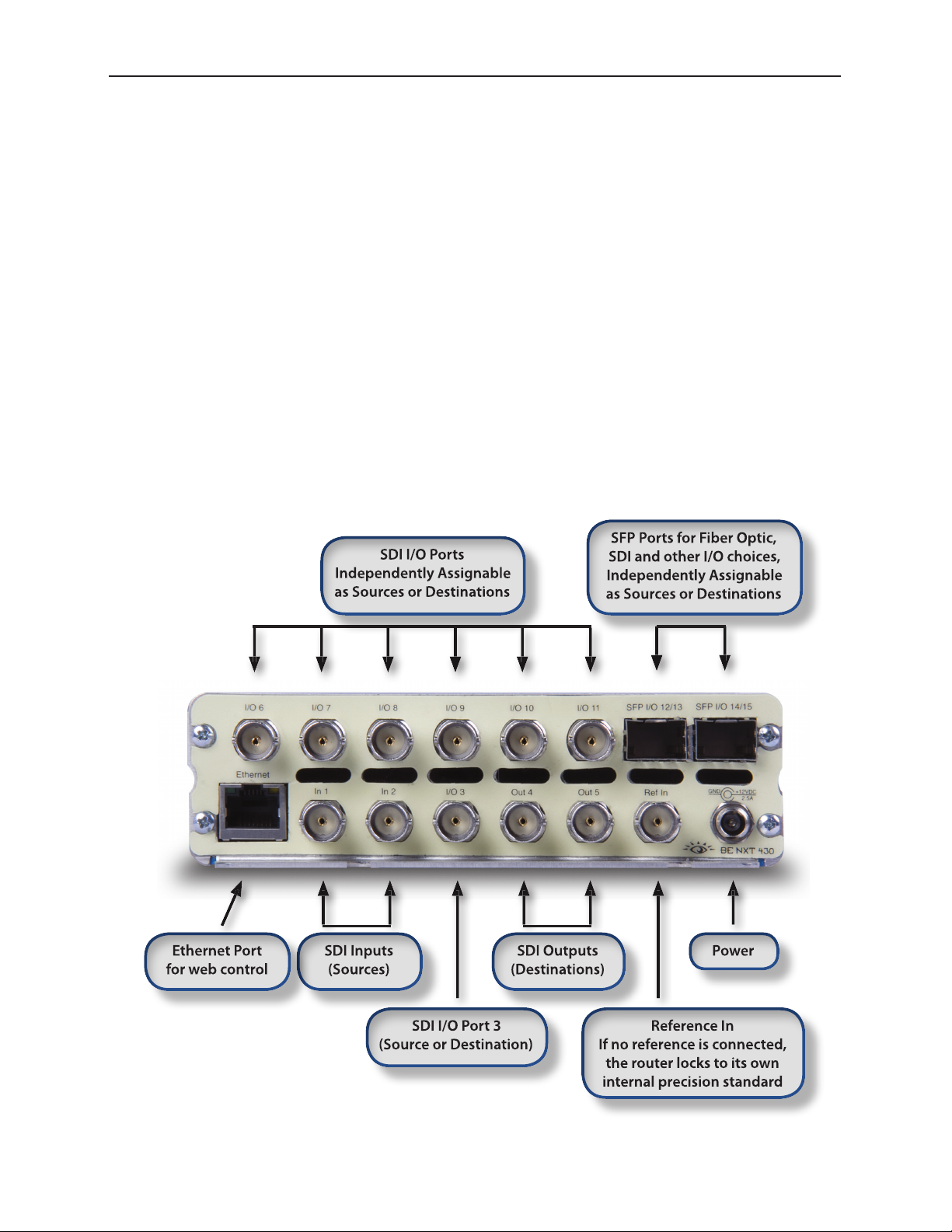
BrightEye NXT 415 and 430 Compact Routers
The BrightEye NXT 430 Router provides clean, quiet switching of video and audio sources. The front
panel LCD displays realtime full motion video of your router sources. The BrightEye NXT 430 Router
gives you two assignable clean switched outputs. The 430’s built-in clean switch provides full frame
synchronization which means you can switch cleanly between asynchronous sources. Perform
dissolves and direct takes from the front panel, or with the web browser interface using a computer,
tablet or smartphone. Audio breakaway, audio level adjustments, and audio channel mapping offer
routing flexibility in live applications. Save the entire configuration of the NXT as a data file. Upload
saved settings to replicate the same overall configuration to multiple NXT routers.
The number of inputs and outputs is configurable. There are 2 fixed input BNCs, 2 fixed output
BNCs and 7 independently assignable BNCs that you configure either as inputs or outputs. The two
SFP (small format plugable) cages can be populated with dual SFPs that have fiber optic or other
connectors, allowing you to determine the best connector for your installation. Adding SFPs gives you
flexibility in combining electrical BNC and fiber optic inputs and outputs.
The BrightEye NXT 415 Router has all the capability of the 430, except it does not have clean switched
outputs or audio breakaway.
www.ensembledesigns.com Page 19
Page 20
BrightEye NXT 410/415/430 Compact Router Installation, Configuration and Operations Guide
Default Port Configuration as Shipped from the Factory
410 and 410-H Default Port Configuration
Ports that are Unassigned, such as Port 3, can be configured from the front panel either as a Source or
Destination, as described on page 34. The two Clean Switches (CS) can be assigned to Destinations
as described on page 42.
In 1: Source
In 2: Source
I/O 3: Unassigned
Out 4: Destination
Out 5: Destination
In 6: Source
In 7: Source
In 8: Source
In 9: Source
Out 10: Destination
SFP I/O 11: Unassigned
SFP I/O 12: Unassigned
TSG 1: Source
TSG 2: Source
CS 1: Unassigned
CS 2: Unassigned
415 and 430 Default Port Configuration
The default port configurations for the BrightEye NXT 415 and 430 are shown below. Ports that are
Unassigned, such as Port 3, can be configured from the front panel either as a Source or Destination, as
described on page 34. The two Clean Switches (CS) can be assigned to Destinations as described on
page 42.
In 1: Source
In 2: Source
I/O 3: Unassigned
Out 4: Destination
Out 5: Destination
I/O 6: Unassigned
I/O 7: Unassigned
I/O 8: Unassigned
I/O 9: Unassigned
I/O 10: Unassigned
I/O 11: Unassigned
SFP I/O 12/13: Unassigned
SFP I/O 14/15: Unassigned
TSG 1: Source
TSG 2: Source
CS 1: Unassigned (430 only)
CS 2: Unassigned (430 only)
www.ensembledesigns.com Page 20
Page 21
BrightEye NXT 410/415/430 Compact Router Installation, Configuration and Operations Guide
BrightEye NXT Router
Applications
The flexibility of the BrightEye NXT Compact Router system makes it possible to tailor the inputs
and outputs to suit a diverse range of requirements. The BrightEye NXT Compact Routers can
accommodate many environments and applications, including the following:
• Mobile and portable systems
• QC stations
• Graphics and post-production islands
• ENG trucks
• Edit suites
• Ingest
• Production switcher pre-select
• Driving on-set monitors
• General utility switching
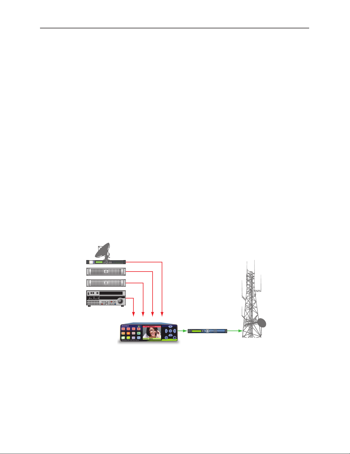
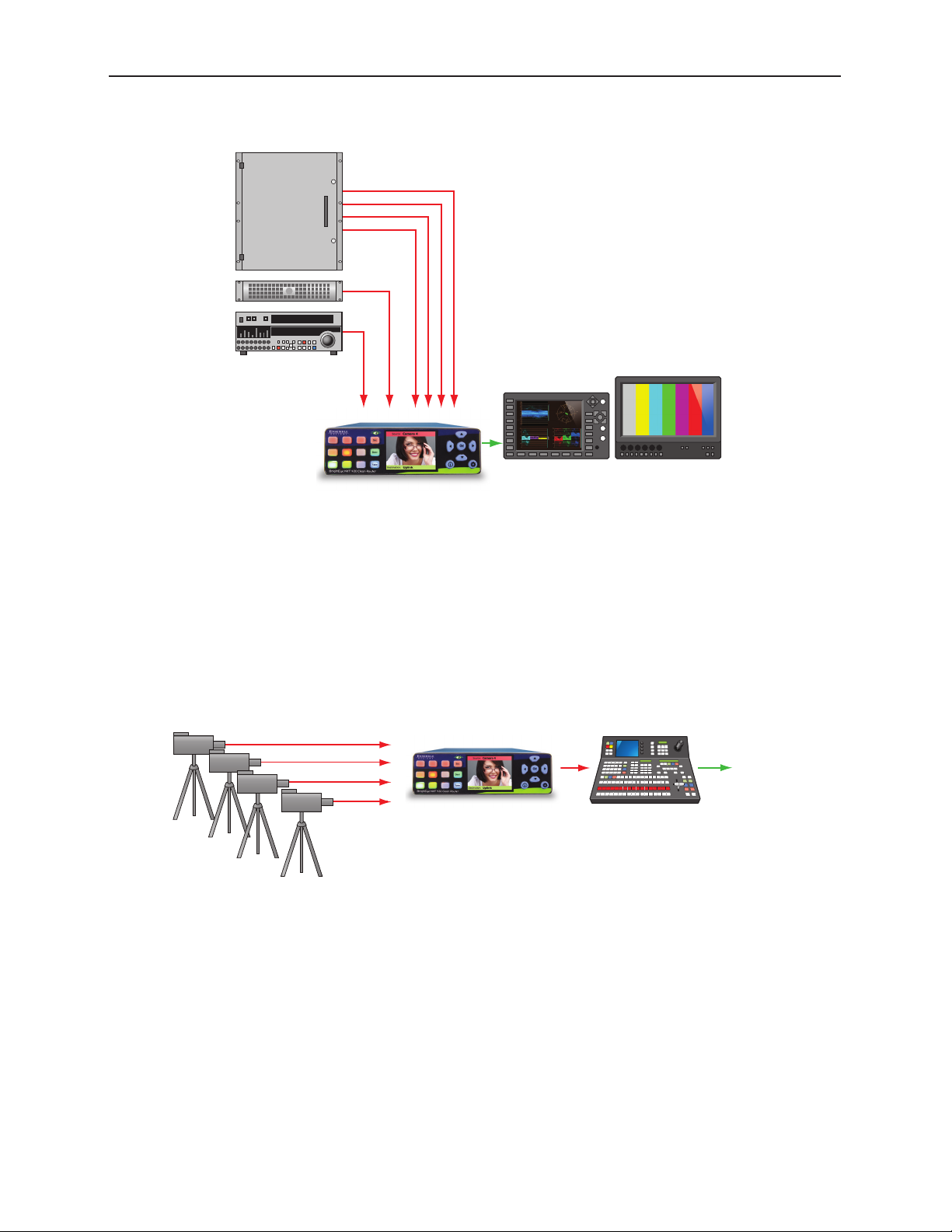
Cuts-Only Master Control
Program Sources
Encoder
Use the BrightEye NXT Router as a cuts-only master control, on the ground or in the air. Great for
helicopters, sports and ENG, the BrightEye NXT Router has built-in frame syncs that let you use sources
that don’t have a reference. The router’s output is clean and quiet, switching seamlessly between
sources. Downstream devices such as routers and encoders receive a consistent video input signal.
www.ensembledesigns.com Page 21
Page 22
BrightEye NXT 410/415/430 Compact Router Installation, Configuration and Operations Guide
BrightEye NXT Router
HDMI
Quality Control and Signal Monitoring
Video and Audio
Sources or
Facility Router
Outputs
QC Monitoring Equipment
QC your ingest sources or set top box feeds with the BrightEye NXT Router. Verify signal presence right
on the front panel of the router. The BrightEye NXT’s LCD displays full motion, realtime video of your
sources. Take the router outputs to scopes and servers. Use the router’s built-in web browser and QC
your sources remotely.
Multi-Stage Venue
3G SDI
Fiber Optic
SDI
Production SwitcherBrightEye NXT 410 Router
Add more inputs to your production switcher or master control switcher. Feed cameras and other SDI
and HDMI sources to a BrightEye NXT 410 Router and take one or more of the router outputs into the
production switcher or master control switcher. This is also a great way to integrate HDMI signals into
an SDI workflow.
To Air
www.ensembledesigns.com Page 22
Page 23
BrightEye NXT 410/415/430 Compact Router Installation, Configuration and Operations Guide
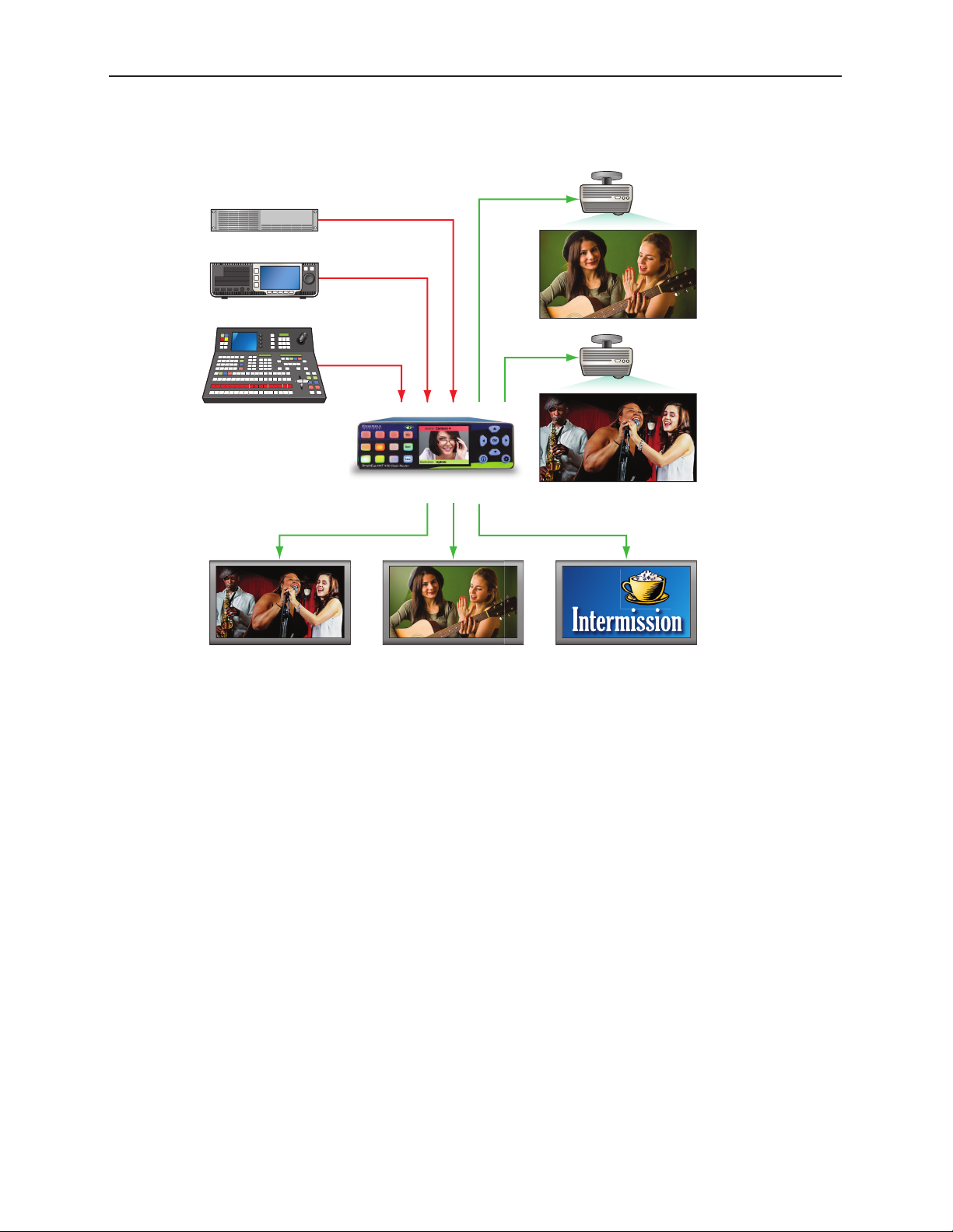
Pr
Monitors and Projectors for Venues
Still Store
Server
oduction Switcher
BrightEye NXT Router
Monitors
Projectors
Use the BrightEye NXT Router for live events and sports to route signals to monitors, switchers and
projectors. The router’s outputs can be easily configured to be in time with house, even when there are
asynchronous sources on the input. Switch seamlessly between fiber optic, HDMI and SDI signals.
www.ensembledesigns.com Page 23
Page 24

BrightEye NXT 410/415/430 Compact Router Installation, Configuration and Operations Guide
Chapter 3: Installation
In this Chapter
This chapter describes cable connections for the installation process. Topics addressed include:
• Connecting Cables to Ports
• Connecting a Reference If Needed
• Connecting the Power Supply
• Connecting Ethernet for Web Control Point (Optional)
Connecting Cables to Ports
Make your connections to sources and destinations with 75 ohm coaxial cable. The BrightEye NXT 410
accepts HDMI connectors.
Connecting a Reference If Needed
The BrightEye NXT locks to house reference or to its own internal precision standard. Connect your
reference source to the Ref In SDI port on the rear panel. The BrightEye NXT detects and reports ... If no
reference is connected, the router locks to its own internal precision standard.
The reference input of the BrightEye NXT will accept these reference types:
• NTSC or PAL analog video
• Tri-Level Sync
• 10 MHz precision reference
When VITC (Vertical Interval Timecode) is present on NTSC or PAL analog composite reference sources,
it will be available to the Router for event scheduling.
See Setting Up Timing and Genlock on page 48 for more details about configuring the Router’s
Timing and Genlock systems.
www.ensembledesigns.com Page 24
Page 25

BrightEye NXT 410/415/430 Compact Router Installation, Configuration and Operations Guide
Connecting the Power Supply
Each BrightEye NXT unit ships with the following power supply:
• Ensemble Designs Part Number 23600106
• Order Information: BEPS-NXT
• Input: 100-240V, 47-63Hz, 1.5A
• Output: 12V, 5.0A
Note: BrightEye NXTs must be powered by their own product-specific power supply that
comes with each unit. DO NOT use a BrightEye Spider power supply (BEPS6) or
a BrightEye Individual power supply (BEPS, ED part number 23118900) to power
BrightEye NXTs.
The boot up process takes about 40 seconds. When first applying power to the BrightEye NXT unit, the
Configuration button illuminates green for the first ten to fifteen seconds.
Connecting Ethernet for Web Control Point (Optional)
Because you can control and configure the NXT immediately upon boot-up with its built-in front
control panel, it is not required to use the Ethernet connection. However, if you want to configure one
or more web control points, you will need to network to the Ethernet port.
Use CAT5 or CAT6 cabling to connect the Ethernet port to a network Ethernet router or switch to make
it accessible to computers on your network. The Ethernet port will auto-sense cable direction, so a
cross-over cable is not needed.
RS-232 Interface Option
As an option, the BrightEye NXT routers can be equipped with cable that has a 9-pin RS-232 port
installed at the factory.
www.ensembledesigns.com Page 25
Page 26

BrightEye NXT 410/415/430 Compact Router Installation, Configuration and Operations Guide
Chapter 4: Configuration
In this Chapter
This chapter covers the following topics:
• Router Configuration Menus
• Assigning Shortcut Buttons
• Port Configuration
• About Clean Switches and Clean Switch Configuration
• Configuring Clean Switches from the Front Panel
• Configuring Clean Switches from the Web Interface
• Setting Up Timing and Genlock
• Working with the Internal Test Signal Generators
• Setting Up a Web Control Point (Optional)
• Establishing Additional Web Control Points and Access Authentication
• Creating and Editing Profiles
• Security and Administrative Access to Settings
www.ensembledesigns.com Page 26
Page 27
BrightEye NXT 410/415/430 Compact Router Installation, Configuration and Operations Guide
Router Configuration Menus
Two sets of configuration menus are available—one through the front
panel, the other through the web interface. An overview of these
respective sets of menus are given on this page and on page 29.
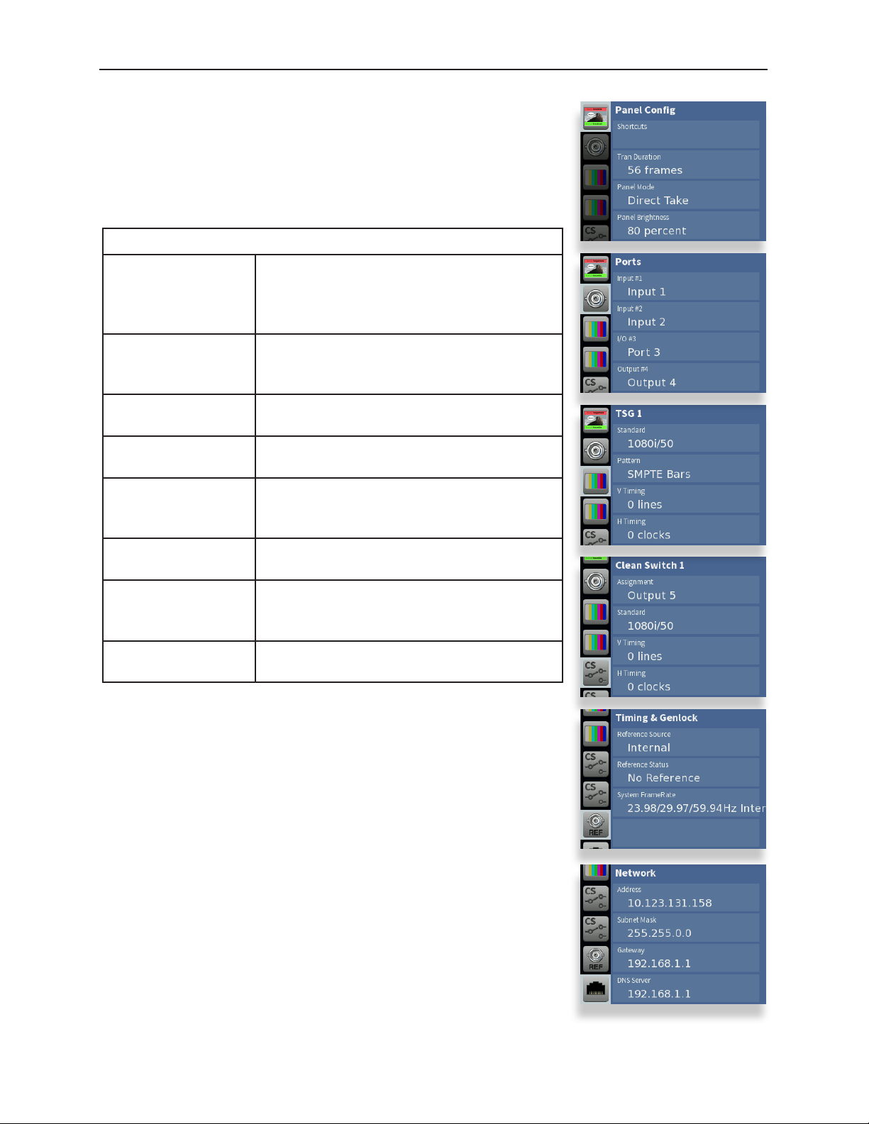
Menus Accessed from the Front Panel
Panel Config Shortcuts, Transition Duration, Direct Take or
Preset/Take, Panel Brightness, Audio Meters,
Meter Reference Level, Peak Display, Live
Video On or Muted
Ports Define ports according to port type, edit
port names, adjust audio levels and audio
mapping
TSG1 Select a test signal, choose its standard,
adjust test signal output timing
TSG2 Same as test signal generator 1, but for the
2nd TSG
Clean Switch 1 Set the clean switch’s standard and assign
it to an output, choose audio breakaway
settings. 410 and 430 units only.
Clean Switch 2 Same as Clean Switch 1, but for the 2nd Clean
Switch
Timing & Genlock Select between external and internal
reference, get info about the system frame
rate (determined by TSG1)
Network Change the router’s IP address and other
network settings
www.ensembledesigns.com Page 27
Page 28
BrightEye NXT 410/415/430 Compact Router Installation, Configuration and Operations Guide
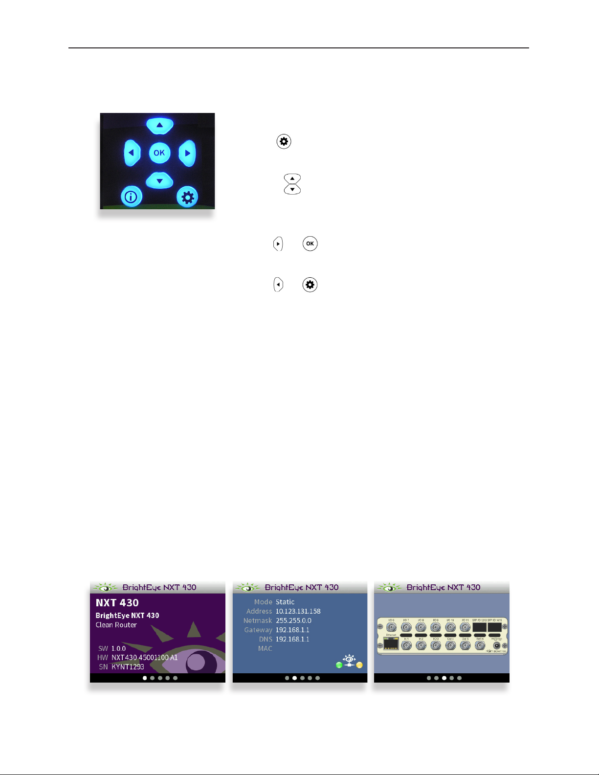
Configuration Controls
All of the configuration buttons are located to the right of the front panel screen.
Front Panel Navigation
Press to bring up the configuration menus on the front
panel screen.
Use the arrows to scroll through the configuration menus,
navigate submenus, or to change the values of a selected
setting.
Press or to drop down successive levels within a
menu.
Press or to come back up one menu level.
Configuration Button
Press the Configuration button to access the configuration menus. Once in the configuration menus,
pressing the Configuration button backs out one level. When in configuration mode, hitting a button
in operations gets you out of configuration mode and immediately into operations mode. Pressing the
Configuration button again brings you right back to the last Configuration menu you visited.
Pressing any operational button—any button to the left of the screen—will take you immediately from
configuration mode to the router’s operational mode.
After approximately 30 seconds of inactivity of the configuration controls, the BrightEye NXT screen
will time out and revert to the router’s operational mode.
Navigation Buttons
Use the Up, Down, Left and Right arrow buttons to navigate the menu system and adjust settings.
Information Button
Press the Info button to access info screens about the NXT unit, such as software version, network
information, rear connectors, SFP port information, and system bootup status.
www.ensembledesigns.com Page 28
Page 29
BrightEye NXT 410/415/430 Compact Router Installation, Configuration and Operations Guide
Menus Accessed from the Web Interface
General Modify the name of the unit. Access
reporting information about model, software
version and serial number. Enable password
requirement or change the password.
Network Change the router’s IP address and other
network settings
Timing & Genlock Select between external and internal
reference, get info about the system frame
rate (determined by TSG1)
Ports Name Sources and Destinations, define ports
as inputs or outputs as needed
Test Signals Select test signals, choose standards, adjust
test signal output timing
Clean Switches Set the standards for both clean switches.
Assign them to outputs, choose audio
breakaway settings. 410 and 430 units only.
Salvos Configure Salvos, enabling you to route a
selected set of sources to a selected set of
destinations simultaneously.
Profiles Create, edit and delete profiles
Control Points Enable control points, assign profiles to
control points
External Control Enable TCP/IP control, select a protocol,
assign a profile
Accessing the web interface
conguration menus
www.ensembledesigns.com Page 29
Page 30
BrightEye NXT 410/415/430 Compact Router Installation, Configuration and Operations Guide
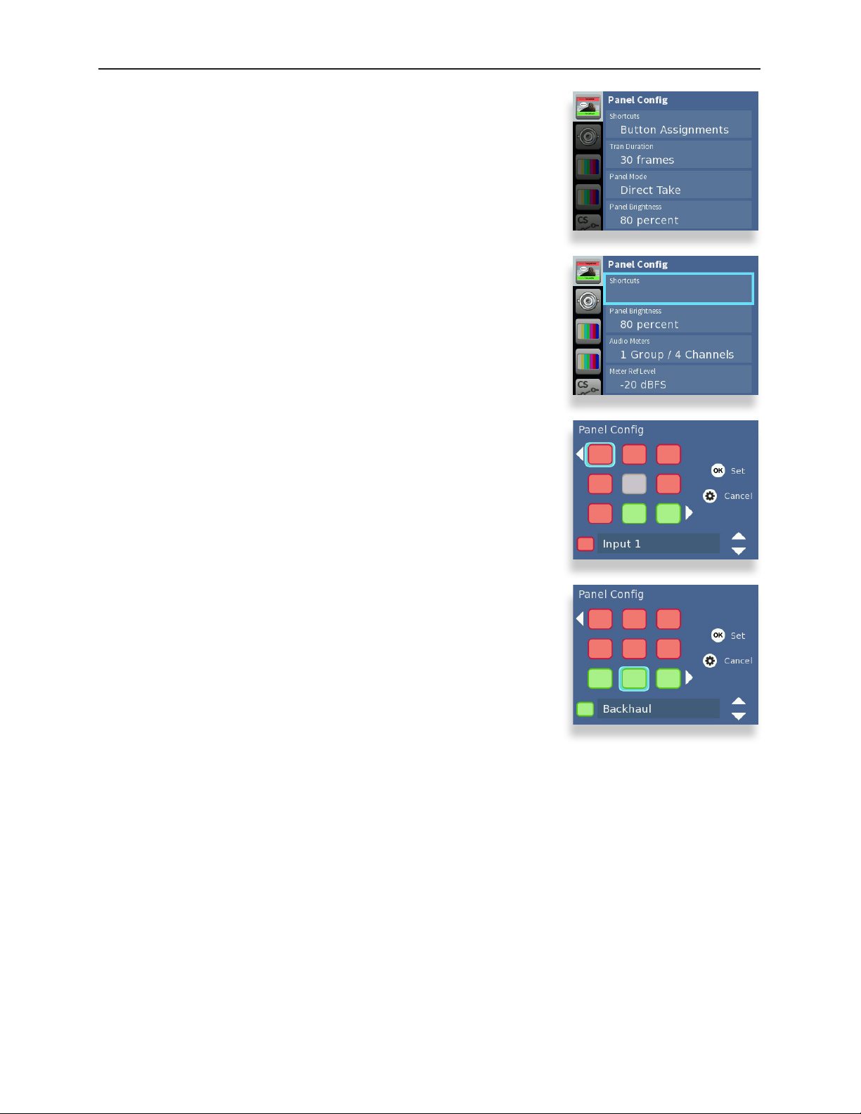
Assigning Shortcut Buttons
Assign Sources and Destinations to the nine shortcut buttons on the
front panel in order to streamline router operation. You can have any
combination of Source, Destination and Unassigned shortcut buttons.
This task can be done only from the BrightEye NXT front panel.
To assign the shortcut buttons:
1. Press the Configuration button. The top level menus display. The
top menu listed is Panel Config.
2. Press the right arrow button (or OK) to highlight the Shortcuts
submenu.
3. Press the right arrow button (or OK) to go to the Panel Config
shortcut button map.
4. Initially, the top left button is selected. Use the left and right arrow
buttons to select the button you want to configure.
5. Use the up and down arrow buttons to change which input, test
signal generator or output to which it is assigned. Or you can map
it to “Unassigned.”
6. Press OK to save your new selection to the highlighted shortcut
button.
7. Press the Configuration button to back out of the menu one
level at a time. Or wait approximately 30 seconds until the screen
automatically returns to Operational mode.
www.ensembledesigns.com Page 30
Page 31

BrightEye NXT 410/415/430 Compact Router Installation, Configuration and Operations Guide
About Port Configuration
Planning Router Port Configuration
Typically, during the planning stage of your Router implementation, you would determine in advance
how you want to initially use the Router in terms of inputs, outputs and test signals.
Cabling Router and Configuring Ports to Match Plan
Based on your plan, connect cables to the ports to match your intended use, and configure the ports
to match how you have wired the router for your facility.
Before going step-by-step through the process of configuring the Router’s ports, it is necessary to go
over some background information in order to understand what the configuration options mean.
Definitions of Port Configuration Choices
Port configuration choices are described below, followed by detailed examples.
Unassigned
For all Port Types
A port can be set to Unassigned when it is not in use. This will remove it from the list of Sources and
Destinations that can be assigned to a Control Profile.
Source
For Fixed Input and Bi-directional Ports
When configured as a Source, a port is an input to the switching matrix. The Source can be given
a name, and under that name it will be available for assignment in a Control Profile. Making this
selection on bi-directional ports will cause them to operate as inputs.
Destination
For Fixed Output and Bi-directional Ports
Configuring a port as a Destination makes it available for use in Control Profiles under its assigned
name as a Router output. A bi-directional port configured as a Destination will cause it to operate as
an output.
Follow
For Fixed Output and Bi-directional Ports
Output capable ports can be configured to Follow, or duplicate, the signal on any Source or
Destination. The Follow configuration essentially makes a port into a DA. Ports that are configured to
Follow will not appear on the list of Sources and Destinations that can be assigned to a Control Profile.
www.ensembledesigns.com Page 31
Page 32

BrightEye NXT 410/415/430 Compact Router Installation, Configuration and Operations Guide
Primary TSG
For Fixed Output and Bi-directional Ports
This Primary TSG configuration delivers the test signal being generated in the Primary TSG to an
output port, independently of any user control of the switching matrix.
Secondary TSG
For Fixed Output and Bi-directional Ports
The Secondary TSG configuration delivers the test signal being generated in the Secondary TSG to an
output port, independently of any user control of the switching matrix.
www.ensembledesigns.com Page 32
Page 33

BrightEye NXT 410/415/430 Compact Router Installation, Configuration and Operations Guide
Port Configuration Choices Available According to Port Type
These three port types (fixed input, fixed output, bi-directional) can be configured in the following
ways:
For Fixed Input
Fixed Input ports can be configured in one of two ways:
1. Unassigned
2. Source (the default on a new installation)
For Fixed Output
Fixed Output ports can be configured in one of five ways:
1. Unassigned
2. Destination (the default on a new installation)
3. Follow
4. Primary TSG
5. Secondary TSG
For Bi-Directional
Bi-directional ports can be configured in one of six ways:
1. Unassigned (default on new installation)
2. Source
3. Destination
4. Follow
5. Primary TSG
6. Secondary TSG
www.ensembledesigns.com Page 33
Page 34

BrightEye NXT 410/415/430 Compact Router Installation, Configuration and Operations Guide
Configuring the Router’s Ports from the
Front Panel
Now that we have covered the background context for numbers and
types of Router ports available and what the various configuration
selections mean, you are ready to configure the Router’s ports.
This section covers assigning ports, renaming ports, adjusting audio
levels, and mapping audio channels.
Port configuration can be done from either the BrightEye NXT front
panel or from the web interface (once a web control point has been
established).
Assigning Ports
Assign each port that you need to use. Once you have assigned a
port, it becomes available to include in a Profile. It’s fine to leave ports
unassigned if you don’t need to use them.
To Assign Ports
1. Press the Configuration button. The top level menus display.
2. Press the down arrow button to select the top level Ports menu.
3. Press the right arrow button (or OK) to highlight the top Ports
submenu.
4. Press the up or down arrow buttons to select the Port you want to
assign.
5. Press the right arrow button (or OK) to go to the Ports
Configuration submenu for your selected Port.
6. Use the up and down arrow buttons to change the Port’s
assignment. The choices available reflect the type of Port you are
working with, whether it is I/O, a dedicated source or a dedicated
destination Port. Dedicated ports can be either what they are, or
they can be disabled by selecting “Unassigned.”
7. Press OK to set your new Port configuration selection, or press the
Configuration button to cancel your selection.
8. Press the Configuration button to back out of the menu one
level at a time. Or wait approximately 30 seconds until the screen
automatically returns to Operational mode.
Repeat steps 1 through 8 for as many Ports as you need to assign for
your facility.
Renaming Ports
Giving ports descriptive names makes them easier to work with. Port
names display in a number of places: on the front panel LCD screen
www.ensembledesigns.com Page 34
Page 35

BrightEye NXT 410/415/430 Compact Router Installation, Configuration and Operations Guide
header and footer, on the front panel Port menus, on the video
thumbnails used in the web interface, on Profiles, and on the Ports
configuration page of the web interface.
To Rename a Port
1. From the Ports Configuration submenu, press the right arrow
button to go to the Port Name submenu.
2. Press the down arrow button to go to the keyboard submenu.
3. Use the up, down, left and right arrow buttons to navigate the
keyboard. Press OK to enter a keyboard character into the label
area. Change case by highlighting and selecting either “abc” or
“ABC.” To backspace or delete letters one at a time, highlight the
“del” key, then press OK.
4. When finished editing the port name, highlight “Set” on the
keyboard and press OK.
Adjusting Audio Levels
When the signal is output through a Clean Switch, you can adjust
audio levels on a per-input and per-channel basis. The BrightEye NXT
compact routers can apply gain or attenuation from +12.0 dB to -70
dB.
When the Clean Switch is in Mix mode, the audio output will properly
mix between the adjusted settings of one input to the adjusted
settings of the new source.
To Adjust Audio Levels
1. From the Port Name menu, press the right arrow button to enter
the Audio Gain menu.
2. Press the down arrow button to go to the Audio Gain editing
screen.
3. Use the right and left arrow buttons to select the channel you
want to modify. The selected channel is indicated by a blue field
surrounding the channel’s level control. In the example to the
right, channel 16 is selected.
4. Press the up or down arrows to adjust the audio levels to be higher
or lower. Press and hold the up or down arrow button to accelerate
the rate of adjustment.
A red marker indicates that gain has been added. A black marker
indicates that gain has been reduced. A green marker indicates
that the audio level is at its default setting.
5. When finished adjusting the audio levels, press the configuration
button to exit and return to the Audio Gain menu.
www.ensembledesigns.com Page 35
Page 36

BrightEye NXT 410/415/430 Compact Router Installation, Configuration and Operations Guide
Mapping Audio Channels
For any given video Input source, which can carry up to 16 audio
channels, any audio Input channel can be assigned to any audio
Output channel.
Each point on the audio map represents a potential cross-point for a
specific audio channel Input and Output. By default, Input 1 is mapped
to Output 1, Input 2 is mapped to Output 2, and so forth. This default
configuration is shown in the middle screen capture to the right.
As a remapping example using Port Input #1, suppose you needed to
switch channels 1 and 2 with channels 3 and 4 on the outputs. Using
the Audio Map menu, you can assign inputs 1 and 2 to outputs 3 and
4, and assign inputs 3 and 4 to outputs 1 and 2. This configuration is
shown in the lower screen capture to the right.
To Remap Audio Channels
1. From the Audio Gain menu, press the right arrow button to access
the Audio Map menu.
2. Press the down arrow button to go to the Audio Map editing
screen.
3. To edit the audio map, use the arrows to select a point on the grid.
4. Press the OK button to activate the selected cross-point. Pressing
the OK button toggles between purple (active cross-point) and
gray (not active cross-point).
5. When finished, press the configuration button to exit.
Inactive cross-point.
www.ensembledesigns.com Page 36
Active cross-point.
Page 37

BrightEye NXT 410/415/430 Compact Router Installation, Configuration and Operations Guide
Configuring the Router’s Ports from the
Web Interface
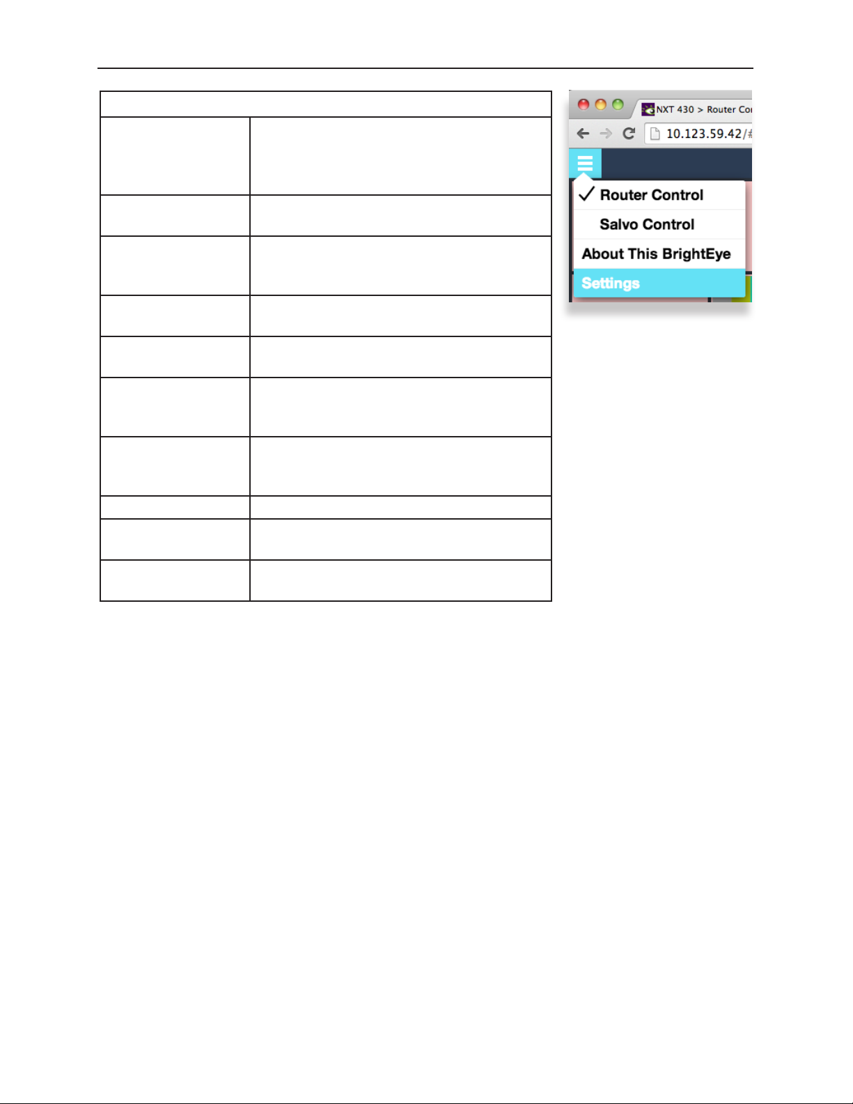
From the upper-left drop-down menu of the web interface, select
Settings. The Settings > General page displays.
Note: If you have not previously established a web control
point, please see: Setting Up a Web Control Point
(Optional) on page 62.
Assigning and Naming Ports
Assign each port that you need to use. Once you have assigned a port, it becomes available to include
in a Profile. It’s fine to leave ports unassigned if you don’t need to use them.
Giving ports descriptive names makes them easier to work with. Port names display in a number of
places: on the front panel LCD screen header and footer, on the front panel Port menus, on the video
thumbnails used in the web interface, on Profiles, and on the Ports configuration page of the web
interface.
To Assign and Name Ports
From the left navigation panel of the Settings > General page, select Ports. The Ports page displays.
Initially, all the non-dedicated ports show “Unassigned” for the Type drop-down control.
For each port that you plan to use, take the following steps:
1. Select its Type from the Type drop-down control.
2. Enter a port name in the Name field.
Conguring Ports: Making a selection from the Type drop-down control for I/O Port 3
www.ensembledesigns.com Page 37
Page 38

BrightEye NXT 410/415/430 Compact Router Installation, Configuration and Operations Guide
3. If applicable, make a selection from the Follow drop-down control.
4. Click Done near the upper left area of the browser window to save your changes.
Adjusting Audio Levels
When the signal is output through a Clean Switch, you can adjust audio levels on a per-input and perchannel basis. The BrightEye NXT compact routers can apply gain or attenuation from +12.0 dB to -70
dB.
When the Clean Switch is in Mix mode, the audio output will properly mix between the adjusted
settings of one input to the adjusted settings of the new source.
To Adjust Audio Levels
1. From the Ports page of the web interface, select the Audio Levels button for the Port you want to
work with. The Audio Level Gain menu displays.
The Audio Level Gain menu for channels 1 - 4 of
Port 1, renamed News Helicopter
2. Click and drag the slider control up or down to adjust the audio levels to be higher or lower for
each channel. Or you can enter a number directly into the field directly beneath the slider control,
or click the + or - symbols to adjust the number incrementally. Click Default to return to the
default value of 0 dB for a specific channel. Click Default All to return the default value to all of the
channels.
3. Select a different button along the top (Ch 5-8, Ch 9-12, Ch 13-16) to access the controls for those
audio channels.
4. When finished adjusting the audio levels, click Done. The Audio Level Gain menu closes, and you
will return to the main Ports page.
www.ensembledesigns.com Page 38
Page 39

BrightEye NXT 410/415/430 Compact Router Installation, Configuration and Operations Guide
Mapping Audio Channels
For any given video Input source, which can carry up to 16 audio channels, any audio Input channel
can be assigned to any audio Output channel.
Columns represent Input Channels, while rows represent Output Channels. Each point on the audio
map shown below represents a potential cross-point for a specific audio channel Input and Output.
By default, Input 1 is mapped to Output 1, Input 2 is mapped to Output 2, and so forth. This default
configuration is shown in the example on the left.
Audio Map default conguration Audio Map congured so that inputs 1 and 2
go to outputs 3 and 4; and inputs 3 and 4 go
to outputs 1 and 2.
As a remapping example using Port Input #1, suppose you needed to switch channels 1 and 2 with
channels 3 and 4 on the outputs. Using the Audio Map menu, you can assign inputs 1 and 2 to outputs
3 and 4, and assign inputs 3 and 4 to outputs 1 and 2. This configuration is shown in the above screen
capture on the right.
To Remap Audio Channels
1. From the Ports page of the web interface, select the Audio Map button for the Port you want to
work with. The Audio Map control displays.
Selecting a point on the grid toggles that point on or off. The grid points that are dark blue are
active; the gray grid points are inactive.
2. Columns represent Input Channels. Rows represent Output Channels. Referencing the example
shown above, click the grid point at column 1, row 1 to make it inactive (gray). Then click the grid
point at column 1, row 3 to make it active (dark blue). The result is that Input Channel 1 is now
going out through Output Channel 3 instead of Output Channel 1.
3. When finished adjusting the audio map, click Done. The Audio Map control closes, and you will
return to the main Ports page.
www.ensembledesigns.com Page 39
Page 40

BrightEye NXT 410/415/430 Compact Router Installation, Configuration and Operations Guide
About Clean Switches and Clean Switch Configuration
The two built-in clean switches for the BrightEye NXT 410 and BrightEye NXT 430 are useful when
switching between asynchronous sources or for taking a router output directly to air. When a Clean
Switch is assigned to an output port, its input is fed from the routing matrix and it drives the output
connector. Any source in the Router switched to this output will be presented synchronously and
timed.
Configuration of the Clean Switch includes its video format, timing, and embedded audio group
enables.
Genlocked to Reference
The Clean Switch is genlocked to the reference being used within the Router. This ensures that the
output is stable regardless of the input signal. Not only does this ensure clean switching between untimed and even asynchronous sources, it also guarantees a stable, Black output upon loss of input.
Embedded Audio
In parallel with the video processing, 16 channels of embedded audio are silently switched as well.
Incoming audio is disembedded, sample rate converted, switched, and then embedded into the
output. The audio processing includes a delay mechanism to compensate for the delay imposed on
the video by the frame sync. This compensation ensures that the time relationship (lip-sync) between
audio and video is maintained.
Output Port Following a Clean Switched Destination
If an output port has been configured to Follow a Destination which has a Clean Switch assignment,
that port will also deliver the Clean Switch output. That port set to Follow will not be seen as a
destination on a control panel because there is still only one Destination. The conceptual effect of this
is to have incorporated an output DA (Distribution Amp) into the Router.
Clean Switch Output Timing
Using the Output Timing control, you can adjust the timing of the Clean Switch relative to the genlock
reference. The best or most appropriate setting for the timing controls will depend upon the way in
which the Clean Switch is to be used and the nature of the video inputs.
Setting the H and V parameters to 0 will “zero” time the Clean Switch, matching it to the reference.
Negative values will cause the Clean Switch to be early with respect to the reference; positive values
will make the Clean Switch output later in time.
Clean Switch / Frame Sync
In Out
Genlock
www.ensembledesigns.com Page 40
Page 41

BrightEye NXT 410/415/430 Compact Router Installation, Configuration and Operations Guide
Imposing Delay on a Video Signal
A video frame sync imposes delay on a video signal passing through it in order to align that input to
the user adjusted output timing. The amount of delay is a function of the difference in timing between
the incoming video and the output of the frame sync. The frame sync can only add delay to the video
in order to make up that difference, and the amount will change automatically in accordance with the
timing of the input signal.
If the input signal is one line early compared to the output, the frame sync will add only one line of
delay. But if the incoming video is just one line late, the frame sync will add nearly an entire frame (less
one line) to bring the signal into time. If the input is asynchronous, its timing will be changing (drifting)
continuously. In that case, the delay imposed by the frame sync will vary continuously between (near)
zero and one frame.
Pre-Selector to a Production Switcher
When a Clean Switch is being used as a pre-selector to a production switcher, the Clean Switch
output timing must fall within the input auto-time window of the switcher. In general, this will be
accomplished by setting the Clean Switch H and V parameters to zero.
Feeding On-Set Monitors in a Live Environment
If the Clean Switch is feeding on-set monitors in a live environment from sources also used on
the production switcher, it is generally desirable to minimize the delay on those monitors. This is
accomplished by setting the Vertical timing of the Clean Switch to a small positive value. Setting this
parameter to +4 lines will typically guarantee that the sources (which have near zero timing) will only
experience 2 or 3 lines of delay. Since most production switchers have a forward delay of 1, 2, or 3 lines,
a setting of +4 lines on the Clean Switch will also allow the switcher output to be used with minimum
delay.
www.ensembledesigns.com Page 41
Page 42

BrightEye NXT 410/415/430 Compact Router Installation, Configuration and Operations Guide
Configuring Clean Switches from the
Front Panel
For the routers to switch cleanly between sources, both sources
need to be in the same standard and the Clean Switch needs to
be configured to that standard, too. For example, if you are using
1080i/50 signals, set the Clean Switch to 1080i/50. Note that if you
feed a signal to the Clean Switch that is set to a different standard
(for example, if a 525 SD signal is fed to a Clean Switch that is set to
1080i/50), the Clean Switch will output black and silence.
To Assign a Clean Switch to a Destination
1. Press the Configuration button. The top level menus display.
2. Use the up or down arrow buttons to select the top level menu for
either Clean Switch 1 or Clean Switch 2.
3. Press the right arrow button (or OK) to highlight the Assignment
submenu.
4. Press the right arrow button (or OK) to go to the Assignment
selection submenu.
5. Press the up or down arrow buttons to select the destination Port
to which you want to assign the selected Clean Switch.
6. Press OK to set your new Clean Switch assignment, or press the
Configuration button to cancel your selection.
7. Press the Configuration button to back out of the menu one
level at a time. Or wait approximately 30 seconds until the screen
automatically returns to Operational mode.
To Set the Standard for Clean Switches
1. From the Clean Switch top level menu, use the up or down arrow
buttons to navigate to the Standard menu.
2. Press the right arrow button (or OK) to go to the Clean Switch
Standard submenu.
3. Use the up or down arrow buttons to select the standard you want
the Clean Switch to use.
4. Press OK to set the standard to your new selection, or press the
Configuration button to cancel your selection.
5. Press the Configuration button to back out of the menu one
level at a time. Or wait approximately 30 seconds until the screen
automatically returns to Operational mode.
www.ensembledesigns.com Page 42
Page 43

BrightEye NXT 410/415/430 Compact Router Installation, Configuration and Operations Guide
To Set the Output Timing for Clean Switches
Using the Output Timing control, you can adjust the timing of the
Clean Switch relative to the genlock reference. Setting the H and V
parameters to 0 will “zero” time the Clean Switch, matching it to the
reference. Negative values will cause the Clean Switch to be early with
respect to the reference; positive values will make the Clean Switch
output later in time.
1. From the Clean Switch top level menu, use the up or down arrow
buttons to navigate to the V Timing or H Timing menu.
2. Press the right arrow button (or OK) to go to the Clean Switch V
Timing or H Timing submenu.
3. Use the up or down arrow buttons to indicate the timing setting
you want the Clean Switch to use.
4. Press OK to set the timing to your new selection, or press the
Configuration button to cancel your selection.
5. Press the Configuration button to back out of the menu one
level at a time. Or wait approximately 30 seconds until the screen
automatically returns to Operational mode.
To Set the Audio Enables for Clean Switches
The Clean Switch supports 16 channels (four groups) of embedded
audio. In order for the Clean Switch output to have a consistent
configuration of audio, regardless of what is present on the input,
individual enables are provided for each group.
The Clean Switch output will always contain the enabled groups, but
channels that are not present in the input will simply be silent. In this
way, switching between sources with differing audio configurations
will produce smooth, silent transitions.
If you are using embedded audio, enable the appropriate audio
groups.
1. From the Clean Switch top level menu, use the up or down arrow
buttons to navigate to the Audio Enables menu.
2. Press the right arrow button (or OK) to go to the Audio Enables
submenu.
3. Use the right or left arrow buttons to navigate to the submenu you
want to work with: Group 1, Group 2, Group 3 or Group 4.
4. Use the up or down arrow buttons to select On or Off.
5. Press OK to set your new selection, or press the Configuration
button to cancel your selection.
6. Press the Configuration button to back out of the menu one
level at a time. Or wait approximately 30 seconds until the screen
automatically returns to Operational mode.
www.ensembledesigns.com Page 43
Page 44

BrightEye NXT 410/415/430 Compact Router Installation, Configuration and Operations Guide
To Set Audio Breakaway
Audio Breakaway is accessed through the following Clean Switch
menus:
1. From the Clean Switch top level menu, use the up or down arrow
buttons to navigate to the Audio Source menu.
2. Press the right arrow button (or OK) to go to the Audio Source
submenu.
3. Use the up or down arrow buttons to select the audio source you
want to designate for the Clean Switch.
4. Press OK to set your new selection, or press the Configuration
button to cancel your selection.
5. Press the Configuration button to back out of the menu one
level at a time. Or wait approximately 30 seconds until the screen
automatically returns to Operational mode.
www.ensembledesigns.com Page 44
Page 45

BrightEye NXT 410/415/430 Compact Router Installation, Configuration and Operations Guide
Configuring Clean Switches from the Web Interface
There are two sets of configuration controls, one for each of the two Clean Switches. Clean Switch 1
and Clean Switch 2 are configured independently.
The Clean Switch conguration page from the web interface
www.ensembledesigns.com Page 45
Page 46

BrightEye NXT 410/415/430 Compact Router Installation, Configuration and Operations Guide
The web interface configuration controls for the Clean
Switches are as follows:
To Assign a Clean Switch to a Destination
Assign the Clean Switch to any of the Destinations
(Output Ports) that have been configured in the Port
Configuration menu. Only the currently available
Destinations will be presented as choices in this
menu. Because only one CS can be assigned to any
given Destination, the list presented will not include
any ports that are already assigned to other Clean
Switches. In order to change assignments to move a
port from one CS to another CS, you must first release
the original assignment by selecting “Unassigned.”
Output 4 and Output 5 are the default Ports
available for Clean Switch assignment.
To Set the Standard for Clean Switches
Select the desired operating format and frame rate.
Only input signals matching that Standard will be
processed by the Clean Switch.
If a source in a different format is selected, the CS will
be bypassed and the source will be switched to the
output without any processing.
When you assign additional Ports as
Destinations, they become available for
Clean Switch assignment.
www.ensembledesigns.com Page 46
Page 47

BrightEye NXT 410/415/430 Compact Router Installation, Configuration and Operations Guide
To Set the Output Timing for Clean Switches
Using the Output Timing control, you can adjust the timing of the Clean Switch relative to the genlock
reference. Setting the H and V parameters to 0 will “zero” time the Clean Switch, matching it to the
reference. Negative values will cause the Clean Switch to be early with respect to the reference;
positive values will make the Clean Switch output later in time.
To Set the Audio Enables for Clean Switches
The Clean Switch supports 16 channels (four groups) of embedded audio. In order for the Clean
Switch output to have a consistent configuration of audio, regardless of what is present on the input,
individual enables are provided for each group.
The Clean Switch output will always contain the enabled groups, but channels that are not present
in the input will simply be silent. In this way, switching between sources with differing audio
configurations will produce smooth, silent transitions.
To Set the Audio Breakaway for Clean Switches
If you need to configure the audio source for the Clean Switch you are using:
• From the Clean Switches web interface page, make an audio source selection from the Audio
Source drop-down menu.
www.ensembledesigns.com Page 47
Page 48

BrightEye NXT 410/415/430 Compact Router Installation, Configuration and Operations Guide
Setting Up Timing and Genlock
The BrightEye NXT Compact Router can be locked to an external
reference or operated from an internal precision reference. The
Reference Source control selects between those two choices.
The Reference Status indicator displays the status of the currently
selected reference.
To Select the Reference Source from the Front Panel
1. Press the Configuration button. The top level menus display.
2. Use the up or down arrow buttons to select the top level menu for
Timing & Genlock.
3. Press the right arrow button (or OK) to highlight the Reference
Source submenu.
4. Press the right arrow button (or OK) to go to the Reference Source
selection submenu.
5. Press the up or down arrow buttons to select Internal or External.
6. Press OK to set your Reference Source selection, or press the
Configuration button to cancel your selection.
7. Press the Configuration button to back out of the menu one
level at a time. Or wait approximately 30 seconds until the screen
automatically returns to Operational mode.
The BrightEye NXT uses the video format selection of the Primary Test
Signal Generator to determine two system-wide parameters—System
Frame Rate, and Vertical Interval Switch Point.
System Frame Rate
Distributed within the BrightEye NXT is a System Frame Rate Reference.
It is used to vertically lock the outputs of the internal Test Signal
Generators and the Clean Switch frame syncs. The System Frame Rate
is selected by the Primary Test Signal Generator. If the selected genlock
reference is in the same frame rate family (see the Note on Frame Rates
on the next page), the System Frame Rate Reference will also be locked
to the external reference. If the external reference is in a conflicting
frame rate family (for example, SD 525 reference vs. 1080p/50 in the
Primary Test Signal Generator), the System Frame Rate Reference will
be internally generated.
Vertical Interval Switch Point
The precise point in the vertical interval where the crosspoint switch
will occur is taken from the timing of the Primary Test Signal Generator.
This provides flexibility in the system by allowing, for example, the use
of an SD reference with a matrix that changes at HD switch points.
www.ensembledesigns.com Page 48
Page 49

BrightEye NXT 410/415/430 Compact Router Installation, Configuration and Operations Guide
To Select the Reference Source from the Web Interface
1. From the left navigation panel of the web interface, select Timing & Genlock. The Timing &
Genlock page displays.
2. From the Reference Source drop-down control, select Internal or External.
3. Click Done near the upper left area of the browser window to save your changes.
Note on Frame Rates
Despite the large number of video formats supported by the Router, there are only three possible
frame rate families.
50 Hz
59.94 Hz
60 Hz
The vast majority of applications, even those including both SD and HD formats, will all fall within a
single frame rate family. For example, as members of the 59.94 family, both SD 525 and 1080i/59.94
can be simultaneously vertically locked to a single reference.
The 50 Hz frame rate family includes 25 Hz and 50 Hz frame and field rates.
This family includes all of the “PAL” related standards in both standard and
high definition.
All of the NTSC-derived standards, including 23.98, 29.97, and 59.94 Hz
field and frame rates. There is a 4 Frame to 5 Frame relationship between
23.98 and 59.94 which allows these to peacefully co-exist.
The “not quite 60 Hz” challenges of the 59.94 world are addressed with this
family which includes 24 Hz, 30 Hz, and 60 Hz field and frame rates. Though
not used for broadcast, this family is useful for film rate and scientific/
industrial applications.
www.ensembledesigns.com Page 49
Page 50

BrightEye NXT 410/415/430 Compact Router Installation, Configuration and Operations Guide
Working with the Internal Test Signal Generators
The BrightEye NXT Compact Router is equipped with two independent internal Test Signal Generators
(TSG). These generators are driven from the genlock source chosen by the Reference Source control on
the Timing and Genlock menu.
Each TSG can be independently configured for format, Router Front Panel rate, and test pattern. The
TSG outputs will always be clock-locked to the reference source. Further, they will be vertically locked
and timed if the video standard the TSG is configured for is compatible with the provided reference.
Because the BrightEye NXT Router generates the test signals internally, the TSGs are available as
sources in the Router (without consuming a physical input BNC) and can be selected to any output
destination. Source names can be assigned to them in the Port Configuration menu, and their position
on control panels is assigned in the Profiles menu.
Configuring the Internal Test Signal Generators from the Front Panel
There are two sets of configuration controls, one for each TSG, for both the BrightEye NXT front panel
and the web interface. These configurations are independent, allowing the two generators to operate
in different formats, and even at different frame rates. To configure them to the same standard, and to
set them to matching timing (relative to the genlock reference), make the same settings for Standard,
Vertical Timing, and Horizontal Timing.
Master
Reference
Input
Internal
Precision
Reference
Tone
Gen
Test Sig
Gen 1
Slate/
Cyclops
Audio
Embed
Genlock
Test Sig
Gen 2
Slate/
Cyclops
Audio
Embed
www.ensembledesigns.com Page 50
Page 51

BrightEye NXT 410/415/430 Compact Router Installation, Configuration and Operations Guide
To Select the TSG Standard
1. Press the Configuration button. The top level menus display.
2. Use the up or down arrow buttons to select the top level menu for
TSG1 or TSG2.
3. Press the right arrow button (or OK) to highlight the Standard
submenu.
4. Press the right arrow button (or OK) to go to the Standard selection
submenu.
5. Press the up or down arrow buttons to select the Standard you
want to use.
6. Press OK to set your Standard selection, or press the Configuration
button to cancel your selection.
7. Press the Configuration button to back out of the menu one
level at a time. Or wait approximately 30 seconds until the screen
automatically returns to Operational mode.
The BrightEye NXT uses the video format selection of the Primary Test
Signal Generator to determine two system-wide parameters—System
Frame Rate, and Vertical Interval Switch Point.
To Select the TSG Pattern
1. Press the Configuration button. The top level menus display.
2. Use the up or down arrow buttons to select the top level menu for
TSG1 or TSG2.
3. Press the right arrow button (or OK) to access the top level of the
submenus.
4. Use the up or down arrow buttons to highlight the Pattern
submenu.
5. Press the right arrow buton (or OK) to go to the Pattern selection
submenu.
6. Press the up or down arrow buttons to select the Pattern you want
to use.
7. Press OK to set your Pattern selection, or press the Configuration
button to cancel your selection.
8. Press the Configuration button to back out of the menu one
level at a time. Or wait approximately 30 seconds until the screen
automatically returns to Operational mode.
www.ensembledesigns.com Page 51
Page 52

BrightEye NXT 410/415/430 Compact Router Installation, Configuration and Operations Guide
To Set the TSG Vertical Timing
1. Press the Configuration button. The top level menus display.
2. Use the up or down arrow buttons to select the top level menu for
TSG1 or TSG2.
3. Press the right arrow button (or OK) to access the TSG submenus.
4. Use the up or down arrow buttons to highlight the V Timing
submenu.
5. Press the right arrow button (or OK) to access the V Timing
selection submenu.
6. Press the up or down arrow buttons to set the lines value you want
to use. If you want to reset V Timing to zero, press both the up and
down arrow buttons simultaneously.
7. Press OK to set your V Timing selection, or press the Configuration
button to cancel your selection.
8. Press the Configuration button to back out of the menu one
level at a time. Or wait approximately 30 seconds until the screen
automatically returns to Operational mode.
To Set the TSG Horizontal Timing
1. Press the Configuration button. The top level menus display.
2. Use the up or down arrow buttons to select the top level menu for
TSG1 or TSG2.
3. Press the right arrow button (or OK) to access the TSG submenus.
4. Use the up or down arrow buttons to highlight the H Timing
submenu.
5. Press the right arrow button (or OK) to access the H Timing
selection submenu.
6. Press the up or down arrow buttons to set the clocks value you
want to use. If you want to reset H Timing to zero, press both the
up and down arrow buttons simultaneously.
7. Press OK to set your H Timing selection, or press the Configuration
button to cancel your selection.
8. Press the Configuration button to back out of the menu one
level at a time. Or wait approximately 30 seconds until the screen
automatically returns to Operational mode.
www.ensembledesigns.com Page 52
Page 53

BrightEye NXT 410/415/430 Compact Router Installation, Configuration and Operations Guide
To Configure the TSG Slate
1. Press the Configuration button. The top level menus display.
2. Use the up or down arrow buttons to select the top level menu for
TSG1 or TSG2.
3. Press the right arrow button (or OK) to access the TSG submenus.
4. Use the up or down arrow buttons to highlight the Slate submenu.
5. Press the right arrow button (or OK) to access the Slate On/Off
selection submenu.
6. Press the up or down arrow buttons to select On or Off.
7. Press OK to set your Slate On/Off selection, or press the
Configuration button to cancel your selection.
8. Press the Configuration button to back out of the menu one
level at a time. Or wait approximately 30 seconds until the screen
automatically returns to Operational mode.
To Configure the TSG Slate Text
1. Press the Configuration button. The top level menus display.
2. Use the up or down arrow buttons to select the top level menu for
TSG1 or TSG2.
3. Press the right arrow button (or OK) to access the TSG submenus.
4. Use the up or down arrow buttons to highlight the Slate Text
submenu.
5. Press the right arrow button (or OK) to access the Slate Text
configuration keyboard.
6. Use the up, down, left and right arrow buttons to select one letter
at a time. Press OK to enter each letter, one at a time, into the text
field.
7. When you have finished entering the Slate Text, highlight “Set” on
the Slate Text configuration keyboard, then press OK to save your
changes.
8. Press the Configuration button to back out of the menu one
level at a time. Or wait approximately 30 seconds until the screen
automatically returns to Operational mode.
www.ensembledesigns.com Page 53
Page 54

BrightEye NXT 410/415/430 Compact Router Installation, Configuration and Operations Guide
To Configure the TSG Cyclops
1. Press the Configuration button. The top level menus display.
2. Use the up or down arrow buttons to select the top level menu for
TSG1 or TSG2.
3. Press the right arrow button (or OK) to access the TSG submenus.
4. Use the up or down arrow buttons to highlight the Cyclops
submenu.
5. Press the right arrow button (or OK) to access the Cyclops selection
submenu.
6. Press the up or down arrow buttons to select one of these options:
Off, Cyclops Only, Cyclops Aud Pop, Cyclops Aud Beep.
7. Press OK to set your Cyclops selection, or press the Configuration
button to cancel your selection.
8. Press the Configuration button to back out of the menu one
level at a time. Or wait approximately 30 seconds until the screen
automatically returns to Operational mode.
To Configure the TSG Audio Reference Level
1. Press the Configuration button. The top level menus display.
2. Use the up or down arrow buttons to select the top level menu for
TSG1 or TSG2.
3. Press the right arrow button (or OK) to access the TSG submenus.
4. Use the up or down arrow buttons to highlight the Audio Ref Level
submenu.
5. Press the right arrow button (or OK) to access the Audio Ref Level
selection submenu.
6. Use the up or down arrow buttons to select either -20 dBFS or
-18 dBFS.
7. Press OK to set your selection.
8. Press the Configuration button to back out of the menu one
level at a time. Or wait approximately 30 seconds until the screen
automatically returns to Operational mode.
www.ensembledesigns.com Page 54
Page 55

BrightEye NXT 410/415/430 Compact Router Installation, Configuration and Operations Guide
To Configure the TSG Audio Enables
1. Press the Configuration button. The top level menus display.
2. Use the up or down arrow buttons to select the top level menu for
TSG1 or TSG2.
3. Press the right arrow button (or OK) to access the TSG submenus.
4. Use the up or down arrow buttons to highlight the Audio Enables
submenu.
5. Press the right arrow button (or OK) to access the Audio Enables
selection submenu.
6. Press the right or left arrow buttons to select Group 1, Group 2,
Group 3 or Group 4.
7. Press the up or down arrow buttons to select On or Off.
8. Press OK to set your selection, or press the Configuration button to
cancel your selection.
9. Press the Configuration button to back out of the menu one
level at a time. Or wait approximately 30 seconds until the screen
automatically returns to Operational mode.
www.ensembledesigns.com Page 55
Page 56

BrightEye NXT 410/415/430 Compact Router Installation, Configuration and Operations Guide
To Configure the TSG Audio Channels
1. Press the Configuration button. The top level menus display.
2. Use the up or down arrow buttons to select the top level menu for
TSG1 or TSG2.
3. Press the right arrow button (or OK) to access the TSG submenus.
4. Use the up or down arrow buttons to highlight the Audio Channels
submenu.
5. Press the right arrow button (or OK) to access the Audio Channels
selection submenu.
6. Press the right or left arrow buttons to select a channel ranging
from Channel 1 to Channel 16.
7. Press the up or down arrow buttons to select one of the available
tones or Silence.
8. Press OK to set your selection, or press the Configuration button to
cancel your selection.
9. Press the Configuration button to back out of the menu one
level at a time. Or wait approximately 30 seconds until the screen
automatically returns to Operational mode.
www.ensembledesigns.com Page 56
Page 57

BrightEye NXT 410/415/430 Compact Router Installation, Configuration and Operations Guide
Configuring the Internal Test Signal Generators from the Web Interface
There are two sets of configuration controls, one for each TSG, for both the BrightEye NXT front panel
and the web interface. These configurations are independent, allowing the two generators to operate
in different formats, and even at different frame rates. To configure them to the same standard, and to
set them to matching timing (relative to the genlock reference), make the same settings for Standard,
Vertical Timing, and Horizontal Timing.
The Test Signals conguration page web interface
www.ensembledesigns.com Page 57
Page 58

BrightEye NXT 410/415/430 Compact Router Installation, Configuration and Operations Guide
The configuration controls for the TSGs as are follows:
Standard
Select the desired operating format and frame rate.
Note: The choice of Standard for the Primary Test Signal
Generator sets the System Frame Rate for the entire
Router. This is detailed earlier in the section Setting
Up Timing and Genlock on page 50.
If the Secondary TSG is set to a Standard which is incompatible with
the System Frame Rate (determined by the Primary TSG), then it will
have a free-running H and V. This makes it possible, for example, to
produce both HD1080i/59.94 in the Primary TSG, and 1080i/50 in the
Secondary TSG. Both will have the same frequency accuracy (from the
genlock reference), but only one will be vertically and horizontally
timeable.
Pattern
Choose the desired test pattern to be presented by the TSG.
In addition to Black and Bars, the Pathological test pattern is provided.
Also known as Digital Checkfield, it is a “worst-case” signal that stresses
SDI cable drivers and equalizers. It is extremely useful in proving the
integrity of a system.
www.ensembledesigns.com Page 58
Page 59

BrightEye NXT 410/415/430 Compact Router Installation, Configuration and Operations Guide
Vertical and Horizontal Timing
The Vertical and Horizontal Timing controls adjust the timing of the TSG relative to the genlock
reference. Setting the H and V parameters to 0 will “zero” time the TSG to the reference. Negative
values will cause the TSG to be early with respect to the reference; positive values will make the TSG
later in time.
When the Router is being operated from an external 10 MHz reference, or when it is configured to use
its internal precision frequency reference, there is no external video reference against which H and V
timing can be adjusted. In that case, all of the resources in the router (the TSGs and the Clean Switch/
Synchronizers) will be adjusted against a common, internally generated video timing reference. This
means that they can be adjusted relative to each other. If all of their H and V Timing parameters are
set to identical values (like 0), they will all be locked (synchronous) to each other and they will all be in
vertical and horizontal alignment with each other.
Note: The timing adjustments for the Primary Test Signal Generator are also used to
position the vertical interval switching point in the Router’s matrix. The timing of the
Primary TSG can be compared to other sources on a Waveform Monitor to ensure
that the switch point will be properly aligned to the sources feeding the Router.
Audio Embedding
Each TSG has an Audio Embedder (Multiplexer) that can embed 16 channels of audio into the TSG SDI
output. Audio is embedded in groups, each of which contains 4 channels. There are 9 audio sources for
each channel – 8 tone generators, plus silence.
Note: In the world of digital audio, there is a big difference between “Silence” and “no
signal present.” In the same way that Black is a legitimate video signal, digital silence
must be sent to destinations rather than just sending “nothing.” Thus, TSGs should
generally be configured to embed ALL of the groups that may be in use in a facility,
with Silence chosen as the audio signal for channels where no content is needed
or desired. Otherwise, switching between a TSG with only one group enabled, and
a source with two groups of embedded audio present, will produce undesirable
effects in downstream equipment.
www.ensembledesigns.com Page 59
Page 60

BrightEye NXT 410/415/430 Compact Router Installation, Configuration and Operations Guide
Audio Reference Level
This control selects the Digital Reference Level for the audio tone
generators. This sets the nominal reference level (or 0 VU) relative to
Digital Full Scale (DFS). This relationship is expressed on a logarithmic
(decibel) scale. Since DFS is the ‘loudest’ signal that can be represented,
a setting of -18 dBFS will be 18 dB below Full Scale which is 2dB greater
than a setting of -20 dBFS. This control should be set in accordance
with the audio practice in use in your facility. Frequently, -20 dBFS is
the common practice in NTSC countries, while -18 dBFS is used in PAL
countries.
Audio Group Enable
Each of the four possible audio groups can be Enabled independently.
Audio Source Selection
Choose between Silence, or one of eight tone frequencies. The tone
generators produce sine waves with precision at 24 bits of quantization.
This can be verified with a digital audio distortion analyzer with a noise
floor at -144 dBFS.
Any tones that are selected will be dynamically modified if the Cyclops
control is configured for Audio Pop or Beep. (The Cyclops control adds
motion, audio pop or beep, and closed caption elements to the video
test signal which proves that the signal reaching a given destination is a
true live signal and not a freeze frame from a frame synchronizer that has
lost its input.)
www.ensembledesigns.com Page 60
Page 61

BrightEye NXT 410/415/430 Compact Router Installation, Configuration and Operations Guide
Slate On
When on, the text which has been entered in the Slate Text field will appear over top of the test
pattern.
Slate Text
Enter the desired Slate text in this field, then hit the Tab key or click outside of the Slate Text field. As
with all of the configuration settings in the Router, this will be saved in non-volatile memory so that
it persists when the Router is powered down. The text entered in this field is not lost when the Slate
Enable is turned off.
Cyclops
In order to produce a dynamic, constantly changing Test Pattern, enable one of the Cyclops modes to
affect the picture, sound or both. The Cyclops feature adds a motion element which is overlaid over
the test pattern video. It is located below the Slate field. The white cyclops pulse continuously sweeps
horizontally back and forth in its black window. At the left and right extremes of its excursion the pulse
makes a one frame bright flash.
Meanwhile, the Beep/Pop feature will add variety to the tones carried
by the embedded audio. Selecting Beep will produce a short beep (and
is otherwise silent), while Pop momentarily takes the selected tone to
silence. Industry practice identifies odd numbered channels as carrying
Left content, and even numbered channels as the Right half of a stereo
program. The Pop and Beep timing in the audio follows this convention,
with the odd channels being marked when the Cyclops makes its left
flash, and the even channels marked when the right edge flash occurs.
Further, the ‘left’ channel is a single Beep/Pop, while the ‘right’ channel is a double Beep/Pop. This
allows left/right identification even after the audio has been disembedded (demultiplexed) and has
lost the implied channel association.
These aural and visual markers provide proof at downstream points in a transmission chain that it
is producing live, uninterrupted delivery of content – even when not in active service. The precise
synchronization between the visual Cyclops and the aural Beep/Pop are also useful to verify sound/
picture lip-sync.
www.ensembledesigns.com Page 61
Page 62

BrightEye NXT 410/415/430 Compact Router Installation, Configuration and Operations Guide
Setting Up a Web Control Point (Optional)
Because the BrightEye NXT includes the built-in front control panel, it is not required to set up a web
control point. However, creating one or more web control points adds flexibility to both configuring
and operating your BrightEye NXT router.
Connecting an Ethernet Cable
Your BrightEye NXT unit is equipped with an Ethernet interface. To establish network connectivity
between a web control point and the BrightEye NXT, connect an Ethernet cable to the Ethernet port
on the rear panel while the power is off. The Ethernet port should be connected with CAT5 or CAT6
cabling to a network Ethernet router or switch to make the BrightEye NXT accessible to computers on
the network. The Ethernet port will auto-sense cable direction, so a cross-over cable is not needed.
Assigning the BrightEye NXT a New IP Address and Subnet Mask
When you initially power up the BrightEye NXT as received from the factory, it will take the selfassigned static IP address of 192.168.1.100. You must modify its IP address and subnet mask to be
compatible with your network’s environment. These are general instructions. We recommend that you
consult your IT staff if you are uncertain about any of these network configuration settings.
To Set the IP Address
1. Press the Configuration button. The top level menus display.
2. Press the down arrow button until the Network top level menu is
selected.
3. Press the right arrow button (or OK) to highlight the Address
submenu.
4. Press the right arrow button (or OK) to go to the Address selection
submenu.
5. Using the arrow buttons, modify the fields in the Address submenu
with an IP address that is compatible with your network. For
example, you may want to change the IP address to something like
the following: 10.123.131.158.
6. Press OK to save the new IP address, or press the Configuration
button to cancel.
www.ensembledesigns.com Page 62
Page 63

BrightEye NXT 410/415/430 Compact Router Installation, Configuration and Operations Guide
To Set the Subnet Mask
The subnet mask must be set in accordance with the size and topology
of your network. The default setting as received from the factory is
for a smaller network: 255.255.255.0. For a larger network, a typical
setting is 255.255.0.0. If in doubt, use the setting for a larger network.
1. Press the Configuration button. The top level menus display.
2. Press the down arrow button until the Network top level menu is
selected.
3. Press the right arrow button (or OK) to highlight the Address
submenu.
4. Press the down arrow button to highlight the Subnet Mask
submenu.
5. Press the right arrow button (or OK) to go to the Subnet Mask
selection submenu.
6. Using the arrow buttons, modify the fields in the Subnet Mask
submenu with an address that is compatible with your network.
7. Press OK to save the new Subnet Mask address, or press the
Configuration button to cancel.
Gateway and DNS Server Settings
Set the Gateway and DNS Server parameters according to your
network configuration. In general, these settings will be required only
in installations with extended networking requirements, such as a
remote site connected by VPN.
You can now browse to the BrightEye NXT from a computer on your
network as described in the next step.
www.ensembledesigns.com Page 63
Page 64

BrightEye NXT 410/415/430 Compact Router Installation, Configuration and Operations Guide
Requesting the Web Control Point
Now that you have set the BrightEye NXT’s IP address in a manner that suits your network
environment, you can connect to the BrightEye NXT to establish a web control point.
1. Navigate to the BrightEye NXT’s new IP address with your web browser. The Control Point Needed
window displays.
2. From the Control Point Needed window, enter the name you want to use to refer to this web
control point; for example, “NXT 430 Admin.”
3. Click Request Control Point. The message “Not Authorized” displays.
www.ensembledesigns.com Page 64
Page 65

BrightEye NXT 410/415/430 Compact Router Installation, Configuration and Operations Guide
4. Click System Settings from the upper left part of the browser
window. The Settings window displays.
5. Click Control Points. The Settings > Control Points window
displays. The Control Point you just requested is shown.
www.ensembledesigns.com Page 65
Page 66

BrightEye NXT 410/415/430 Compact Router Installation, Configuration and Operations Guide
Assigning the Default Profile to the Web Control Point
Next, assign a Profile that defines which sources and destinations this Control Point can access. To
begin with, choose the Factory Default Profile.
1. From the Profile drop-down control, select FactoryDefault.
2. Click Authorize. The NXT Web Control Point now displays in the list of authorized Control Points.
The Control Points window showing two Control Points. Note that these Control Points are
enabled (the Enabled check box is selected) and have Proles assigned to them.
3. Click Done in the upper left area of the window.
www.ensembledesigns.com Page 66
Page 67

BrightEye NXT 410/415/430 Compact Router Installation, Configuration and Operations Guide
You are now presented with a BrightEye NXT Router control view with thumbnail icons, shown below.
Without video signals present, the thumbnails will indicate “No Input.”
Thumbnail representations of the router’s Sources are shown in the upper area,
Destinations in the lower area.
www.ensembledesigns.com Page 67
Page 68

BrightEye NXT 410/415/430 Compact Router Installation, Configuration and Operations Guide
Establishing Additional Web Control Points and Access Authentication
Now that you have established an initial web control point, you can create additional web control
points if you need them. Access can be controlled through using a password as discussed shortly.
Profile assignments also control which sources and destinations any given web control point may
access.
In order to manage web access, each possible Control Point must be authenticated.
An administrator grants access to Control Points through configuring the Control Points page. Access
the Control Points page by selecting Settings > Control Points from the left navigation panel of the
web interface. The administrator assigns a previously created Profile to each of the various Control
Points. Control Points can be either assigned or requested. These methods are discussed in more detail
shortly.
Characteristics of Control Points
For each Control Point, only the Sources and Destinations that have been defined by its assigned
Profile will be available.
For a Control Point to work, it must meet these conditions:
• It must be authenticated, meaning that the Enabled check box is selected in the Control Points
window.
• It must have a Profile assigned to it.
If these conditions are not met, the browser window displays the message, “Control Point Disabled.”
Examples of Control Points
• Laptops
• Desktop computers
• iPads or other tablets using a web browser
• Smartphones
• External control using serial protocols
www.ensembledesigns.com Page 68
Page 69

BrightEye NXT 410/415/430 Compact Router Installation, Configuration and Operations Guide
Configuring Additional Control Points
For control points such as iPads and web browsers, there are two methods for adding them. One
method is to request access from a Control Point. The other method is to assign an IP address to a
Control Point.
First Method: Requesting Access from a Desired Control Point
1. From the desired control point, whether from an iPad or from a computer web browser, enter
the Router's IP address (for example, http://10.123.131.158/) into the browser's address field. A
browser window displays indicating that a Control Point is Needed.
2. Enter your desired Control Point name in the Control Point Name field, then click Request. The
browser window indicates that your Control Point has been disabled. Your request has become a
Pending Authorization item for the administrator.
Second Method: Assigning an IP Address From the Admin Control Point
To assign the IP address of a device to create a Control Point:
1. From the Admin Control Point, navigate to the IP address of the BrightEye NXT.
2. In the upper left area, click Settings. The Settings page displays.
3. From the left navigation panel, click Control Points. The Control Points page displays.
4. Under the heading Add Control Points, indicate a name in the Name field.
5. Select a profile from the Profile drop-down control.
6. Enter the IP address for the device into the Address field.
7. Click Add. The Control Points page refreshes to show that the newly assigned Control Point is
enabled.
Approving Pending Authorizations
To approve an authorization request:
1. Click Settings in the upper left area of the browser.
2. Click Control Points in the left navigation panel. The Control Points page displays.
3. Under Pending Authorizations, you will see the request that was just submitted.
4. For this new request, select a Profile from the drop-down control.
5. Click Authorize. The Control Points page refreshes and now includes the newly requested Control
Point.
Note: In order to access Settings, you must have administrator access. See Security and
Administrative Access to Settings on page 78 for more details.
www.ensembledesigns.com Page 69
Page 70

BrightEye NXT 410/415/430 Compact Router Installation, Configuration and Operations Guide
Number of Control Points That Can Operate Simultaneously
The BrightEye NXT performs best with a maximum of four control points operating simultaneously.
The Router’s data bandwidth is shared across all of the control points. Each additional control point
adds an incremental load on the system. When more than four control points are being used, the
BrightEye NXT’s video thumbnail display performance in web browsers may begin to degrade.
Asymmetrical Bandwidth Requirements
The continuous delivery of video thumbnails to each Web Browser Control Point requires more
bandwidth than is required for performing takes. The video thumbnails, comprising the vast bulk
of the data, flow outward from the BrightEye NXT to each Web Control Point. The return data, in
contrast, consists primarily of crosspoint commands, or takes. Because the BrightEye NXT has greater
bandwidth for takes, the execution of takes will still be quite responsive even in a large system with
markedly degraded video refresh performance.
Best Practice: Closing Web Browser Control Points When Not In Use
To minimize the load on the BrightEye NXT, it is recommended to close any Web Browser Control
Points that are not being used.
www.ensembledesigns.com Page 70
Page 71

BrightEye NXT 410/415/430 Compact Router Installation, Configuration and Operations Guide
Creating and Editing Profiles
A Profile provides each Control Point with a configured view of the Sources and Destinations on the
Router. A Profile defines which Sources and Destinations can be accessed from any given Control
Point.
A Profile also defines the order in which Sources and Destinations display for a Control Point. This
ordering feature is of particular interest in the case of RS-232 and TCP/IP control for automation
because it provides a simple means to map Sources and Destinations to suit the automation protocol.
Every Control Point, such as a web browser, an iPad, or a serial interface for external control, must have
a Profile assigned to it in order for that Control Point to be able to use the Router. Multiple Control
Points can share the same Profile.
Each Profile can be customized to have access to unique combinations of not only Destinations, but
also Sources.
Characteristics of Profiles
• Required for every Control Point
• Show only Sources and Destinations
• Define which Sources and Destinations can be accessed
• Define the order in which Sources and Destinations are displayed
• Can be assigned to multiple Control Points
Creating an Initial Set of Profiles
Complete the process of creating as many profiles as your Router users will require. While you can
always create additional Profiles or edit existing ones, you may want to systematically think through
your users’ needs to determine what the initial set of Profiles will be. This will simplify the overall
configuration process as you begin assigning Profiles to Control Points.
To Create a Profile
1. From the left navigation panel, click Profiles. The Profiles page displays.
2. Enter a profile name in the New Profile field.
3. Click Create. The new Profile is listed on the Profiles page.
4. Next to the newly created Profile, click Edit. The Edit Profile page displays. At the outset of creating
a new profile, all the available Sources and Destinations are presented.
5. Click and drag unassigned Sources and Destinations up to the assigned area as needed for this
specific profile. Note that you can rearrange the order as desired. Additionally, you can include
empty spaces to create groupings of Sources and Destinations by clicking and dragging a Space
icon up to be a source or destination.
6. When finished, click Save Changes in the upper left part of the screen, then click Done.
This newly created Profile is now available to assign to one or more Control Points.
Repeat steps 1 through 6 until you have as many Profiles as you need.
www.ensembledesigns.com Page 71
Page 72

BrightEye NXT 410/415/430 Compact Router Installation, Configuration and Operations Guide
Examples of Profiles
After the functions of the Ports have been defined, the available Sources and Destinations are
selectively assigned to Profiles.
Ports that are configured as Follow or Unassigned are not available to a Profile since they cannot be
“controlled.”
Master Control Room (MCR) 10 x 2
In the example below, there are ten Sources and two Destinations for a Master Control Room Profile
named “MCR.”
An example of a Master Control Room (MCR) Prole
with 10 Sources and 2 Destinations
www.ensembledesigns.com Page 72
Page 73

BrightEye NXT 410/415/430 Compact Router Installation, Configuration and Operations Guide
MCR Profile Edited and Reordered to 8 x 2
This Profile has been edited to remove access to two of the Sources (ENG Rx 1 and News 1). In addition,
blank spaces have been inserted to organize the selections as they are presented on a control panel.
Those “blanks” will produce unused buttons on the panel.
This profile also has the Sources and Destinations in a different order and will be reflected in
the button assignment on a control panel. If this profile were assigned to the serial interface for
automation control, the order and spacing of Sources and Destinations would “map” the external
control to the Router.
An edited and reordered Master Control Room (MCR) Prole
with 8 Sources and 2 Destinations
www.ensembledesigns.com Page 73
Page 74

BrightEye NXT 410/415/430 Compact Router Installation, Configuration and Operations Guide
MCR Profile Edited to 8 x 1
This Profile has been further edited by removing a Destination. The result is a Profile that allows control
over only a single output.
An edited Master Control Room (MCR) Prole with 8 Sources and 1 Destination
www.ensembledesigns.com Page 74
Page 75

BrightEye NXT 410/415/430 Compact Router Installation, Configuration and Operations Guide
Setting Up Salvos
Salvos enable you to route a selected set of sources to a selected set of destinations simultaneously.
Salvos provide an efficient method for switching among multiple sets of routing configurations with
one click. You can configure and save up to eight Salvo configurations.
A single Salvo can include mixes with various duration times, direct takes, audio level adjustments and
audio channel mapping settings among multiple sources and destinations.
For example, in a situation in which you need to have several different on-stage monitor
configurations for a number of different uses, with Salvos set up and configured in advance, you can
very efficiently switch from one multiple monitor arrangement to another.
The two methods of creating a Salvo described below are similar. The key difference is that with the
first method, you start by routing all the sources you need to all the destinations in advance. Once all
that is in place, you capture the whole routing configuration by clicking Capture Current Routes from
the Salvos Editing page. If you use the second method, you determine which sources are going to
which destinations from the Salvos Editing page.
To Create a Salvo
First Method
1. From the left navigation panel, click Salvos. The Salvos page displays.
www.ensembledesigns.com Page 75
Page 76

BrightEye NXT 410/415/430 Compact Router Installation, Configuration and Operations Guide
2. For the Salvo you are creating (Salvo 1 - Salvo 8), enter a name in the Name field.
3. Click Edit. The Salvos Editing page displays.
4. Using either the front panel or the web interface, route all sources and destinations as you want
them to be for the specific Salvo you are creating, including any transition options for mixing, mix
duration times, or taking.
5. Click the Capture Current Routes button. The current routing configuration is automatically
saved into the Salvo settings.
6. Click Salvos in the upper left part of the screen. The Salvos page displays.
7. Repeat steps 2 through 6 until you have created as many Salvos as you need, up to a maximum of
8.
8. Click Done.
These newly created Salvos are now available to trigger from the Salvo Control page of the web
interface.
Second Method
1. From the left navigation panel, click Salvos. The Salvos page displays.
2. Enter a name in the Name field.
3. Click Edit. The Salvos Editing page displays.
www.ensembledesigns.com Page 76
Page 77

BrightEye NXT 410/415/430 Compact Router Installation, Configuration and Operations Guide
4. At the outset of creating a new Salvo, all the available Destinations are shown. For each
Destination, select the Source you want routed to it from the Source drop-down control. If a Clean
Switch has been assigned to a Destination, you can specify the transition type (Mix or Take), as well
as the mix duration.
5. When finished, click Salvos in the upper left part of the screen. The Salvos page displays.
6. Repeat steps 2 through 5 until you have created as many Salvos as you need, up to a maximum of
eight.
7. Click Done.
These newly created Salvos are now available to trigger from the Salvo Control page of the web
interface.
Accessing the Salvo Control page
www.ensembledesigns.com Page 77
Page 78

BrightEye NXT 410/415/430 Compact Router Installation, Configuration and Operations Guide
Security and Administrative Access to Settings
All of the Router’s configuration parameters can be accessed through the Settings button in the
upper left corner of the web interface. Without enabling a password, anyone with access to the Router
(meaning anyone who has an authorized Control Point with an assigned Profile) can make changes to
its Settings.
Depending on the security needs of your facility, you may wish to limit access to the Router’s Settings
to only certain people. From the General > Settings page, you can limit administrative access to the
Router by creating a password.
To Limit Access to the Router’s Settings
1. From the Router’s web interface, click Settings. The Settings > General page displays.
2. In the Security section, click the Required checkbox to enable the password functionality.
3. Select a password and enter it into the Password field. Enter it a second time in the Repeat
Password field.
4. Click Set Password, then click Done. The main Router web interface displays.
When a password is required for administrative access, users who try
to access Settings will get a message that says “Password Required.”
www.ensembledesigns.com Page 78
Page 79

BrightEye NXT 410/415/430 Compact Router Installation, Configuration and Operations Guide
Saving and Restoring Configuration Settings
You can save and restore the configuration settings of your BrightEye NXT router. The configuration
settings are downloaded as a file with a “.settings” file extension. From this file, you can upload
configuration settings to one or multiple BrightEye NXT routers. The only information not stored is
network settings such as the IP address and Subnet Mask.
To Save Configuration Settings
1. From the Router’s web interface, click Settings. The Settings > General page displays.
2. In the Manage Settings section, click Download Settings. A file downloads immediately in a
manner consistent with your browser’s typical downloading behavior.
3. The configuration file is downloaded to the location where files are typically downloaded
using your browser, such as your desktop or a downloads directory. The BrightEye NXT router
configuration settings are stored in a file with the extension “.settings”. For example:
NXT 430(NXT430-IYNT1226).settings
To Upload Configuration Settings
1. From the Router’s web interface, click Settings. The Settings > General page displays.
2. In the Manage Settings section, click Upload Settings. A navigation window opens.
3. Navigate to the location of your configuration file, select the file, then click Open. The following
message displays:
www.ensembledesigns.com Page 79
Page 80

BrightEye NXT 410/415/430 Compact Router Installation, Configuration and Operations Guide
4. Click Upload Settings. Your browser window will lose its connection to the BrightEye NXT during
the configuration file upload. The uploading process takes a few moments.
5. After your BrightEye NXT router has rebooted, you will need to restore its network settings. See
“Assigning the BrightEye NXT a New IP Address and Subnet Mask” on page 62 for instructions
about that process.
www.ensembledesigns.com Page 80
Page 81

BrightEye NXT 410/415/430 Compact Router Installation, Configuration and Operations Guide
Chapter 5: Operations and Step-by-Step Procedures
In this Chapter
This chapter covers the following topics:
• Operations Using the Front Control Panel
• Operations Using a Web Control Point
This chapter provides complete step-by-step procedures for each task that you can perform with the
BrightEye NXT using the following control choices:
• BrightEye NXT Router Operation Using its Front Panel
• BrightEye NXT Router Operation with the Web Browser Interface
You can use the web browser interface on a desktop computer, tablet or smartphone.
For serial protocols through TCP/IP and RS-232, please see Chapter 6: External Control on page 92.
Operations Using the Front Control Panel
After setting up and configuring the BrightEye NXT, you can start routing sources to destinations. First
we will address how to do this using the front panel. Next, we will address how to do this using the
web interface.
Making a Cross Point Switch in Preset/Take Panel Mode
When using the front panel, always select the destination first, then the source, then press Take.
Selecting a Destination
There are two methods for selecting a destination from the front panel:
1. If you have assigned the destination you want to select to a shortcut key, pressing that shortcut
key selects it. The signal will display on the screen.
2. Otherwise, press Dest to step through all available destinations until you see the one you want
displaying on the screen.
Selecting a Source
Similarly, there are two methods for selecting a source from the front panel:
1. If you have assigned the source you want to select to a shortcut key, pressing that shortcut key
selects it. The signal will display on the screen.
2. Otherwise, press Src to step through all available sources until you see the one you want
displaying on the screen.
www.ensembledesigns.com Page 81
Page 82

BrightEye NXT 410/415/430 Compact Router Installation, Configuration and Operations Guide
Pressing Take
After first selecting the destination, then the source, both the Take button and the selected source
shortcut button blink to show that a Take is available. At that point, pressing Take sends the selected
source to the selected destination. The screen displays the video signal, showing the source and its
port name along the top red header and the destination and its port name along the bottom green
footer.
Performing Direct Takes
Using Direct Take mode, you can change which source is going to a
destination by pushing an assigned source shortcut button. A cross
point switch is made directly without pressing Take.
To Enter Direct Take Panel Mode
• When the BrightEye NXT is not in Direct Take mode, the Take
button illuminates blue.
• Double-tap the blue illuminated Take button. The message
“Panel Mode Direct Take” displays very briefly on the front
panel screen.
• The Take button stops illuminating.
To Make a Direct Take
The currently selected destination shortcut button illuminates bright
green. The source shortcut button that is currently going to the
selected destination illuminates bright red.
To make a direct take, press a different source shortcut button. The
source assigned to that shortcut button is immediately routed to the
already-selected destination.
To Exit Direct Take Panel Mode
• Double-tap the Take button. The message “Panel Mode
Preset / Take” displays very briefly on the front panel screen.
• The Take button illuminates blue.
www.ensembledesigns.com Page 82
Page 83

BrightEye NXT 410/415/430 Compact Router Installation, Configuration and Operations Guide
Performing Mix Takes with the Front Panel
Clean Switch Required
In order to perform a Mix take, the destination must have a Clean
Switch assigned to it. (BrightEye NXT 410, BrightEye NXT 410-H and
BrightEye NXT 430 only.)
To Enter Mix Mode
For this example, Clean Switch 1 is assigned to Output 4, and the Clean
Switch is configured for Audio Follow Video.
• When the BrightEye NXT is not in Mix mode, the footer will be
blue and will indicate “Cut CS1 / AFV”.
• Double-tap the assigned destination shortcut button. The
message “Changing Output 4 Transition to: Mix” displays very
briefly on the front panel screen.
• The footer, now purple, indicates “Mix CS1 / AFV”.
To Make a Mix Take
The currently selected destination shortcut button illuminates bright
green. The source shortcut button that is currently going to the
selected destination illuminates bright red.
To make a mix take, press a different source shortcut button. The
source assigned to that shortcut button is immediately routed to the
already-selected destination. The mix will occur with the mix duration
specified from the Panel Config > Tran Duration menu.
To Exit Mix Mode
• Double-tap the assigned destination shortcut button. The
message “Changing Output 4 Transition to: Cut” displays very
briefly on the front panel screen.
• The footer is now blue, and indicates “Cut CS1 / AFV”.
www.ensembledesigns.com Page 83
Page 84

BrightEye NXT 410/415/430 Compact Router Installation, Configuration and Operations Guide
Viewing Information about a Routed Signal
To view information about a signal that is already being routed to
a destination, press the green Shortcut button that corresponds
to the signal you want information about. The associated red
button illuminates to show which source is currently routed to that
destination.
Additionally, pressing the Right or Left arrow buttons brings up signal
metadata to the screen. The metadata includes horizontal and vertical
timing, signal frame rate and other signal metadata.
Disabling the Front Panel for Safe Driving Mode
If you will be using the BrightEye NXT router while driving a vehicle,
you can put the front panel screen into “safe driving mode,” meaning
that it will not display live video. Instead, it will display the message
“Live Video Display Muted.”
To Enter Safe Driving Mode
1. Press the Configuration button. The top level menus display.
2. Use the up or down arrow buttons to select the top level menu for
Panel Config.
3. Press the right arrow button (or OK) to access the Panel Config
submenus.
4. Press the down arrow button repeatedly until the Live Video
Display submenu is highlighted.
5. Press the right arrow button (or OK) to access the next Live Video
Display submenu.
6. Press the up or down arrow to select either Live Video Muted or
Live Video On.
7. Press OK to set your selection, or press the Configuration button to
cancel your selection.
8. Press the Configuration button to back out of the menu one
level at a time. Or wait approximately 30 seconds until the screen
automatically returns to Operational mode.
www.ensembledesigns.com Page 84
Page 85

BrightEye NXT 410/415/430 Compact Router Installation, Configuration and Operations Guide
Operations Using a Web Control Point
You can control the BrightEye NXT through its web browser user interface to perform takes, direct
takes, gang, and gang combined with direct takes.
Prerequisites
Before you can access the Router through a web browser, you need to have access to an authenticated
Control Point and the Router’s IP address. For further details about these requirements, please see the
following sections:
• Setting Up a Web Control Point (Optional) on page 62
• Establishing Additional Web Control Points and Access Authentication on page 68
Accessing the Web Browser Control Interface
To access the NXT web browser control interface, enter the NXT’s IP address into the browser’s address
bar. The NXT’s router interface displays, showing Sources in the upper area and Destinations in the
lower area.
Performing Takes
While performing a take is a straight forward task, it can be done using more than one method.
To Perform a Take by Selecting a Source and a Destination
1. Select a Source by clicking one of the Source thumbnail images. The thumbnail frame turns red to
indicate that it is selected.
2. Select a Destination by clicking one of the Destination thumbnail images. The thumbnail frame
turns green to indicate that it is selected. As soon as you have selected both a Source and a
Destination, the Take button turns blue, indicating that the Router is ready for a Take.
3. Click Take in the lower right area of the web browser. Your chosen Source is routed to the
Destination you selected. The Destination thumbnail image updates to reflect your currently
selected Source. The Ta ke button is now greyed out.
To Perform a Take by Selecting Only a New Source
As long as the Destination that you want is already selected, you can do a Take by selecting a new
Source, then clicking Take.
1. Leaving the Destination selection unchanged, select a new Source.
2. Click Take . Your chosen Source is routed to the Destination. The Destination thumbnail image
updates to reflect your new Source selection.
www.ensembledesigns.com Page 85
Page 86

BrightEye NXT 410/415/430 Compact Router Installation, Configuration and Operations Guide
Performing Direct Takes
In Direct Take mode, you leave the same Destination selected while selecting different Sources with
only one click. There is no need to click the Take button when in Direct Take mode.
To Perform a Direct Take
1. Click Direct in the lower left area of the browser window. The Direct button turns orange.
2. Select a Destination.
3. Select a Source. The Source is immediately routed to the Destination. The Destination thumbnail
image reflects your newly selected Source.
As long as you remain in Direct Take mode, you can continue to change Sources for the same
Destination with only one click.
To Exit Direct Take Mode
Click Direct in the lower left area of the browser window. The Direct button is now greyed out,
indicating that you are no longer in Direct Take mode.
www.ensembledesigns.com Page 86
Page 87

BrightEye NXT 410/415/430 Compact Router Installation, Configuration and Operations Guide
Performing Gang Takes
Gang Takes involve routing one Source at a time to a set of Destinations.
To Perform a Gang Take
1. Click Gang in the lower left area of the browser window. The Gang button turns orange.
2. Select a Source by clicking one of the Source thumbnail images. The thumbnail frame turns red to
indicate that it is selected.
3. Select a set of Destinations by clicking multiple Destination thumbnail images sequentially. The
first thumbnail frame you select turns green; the remaining thumbnails you select turn yellow.
4. Click Take in the lower right area of the web browser. The Source is routed to the set of
Destinations. The set of selected Destination thumbnail images updates to reflect your selected
Source. The Take button is now greyed out.
You can continue to perform gang takes in this manner as long as you are in Gang mode.
To Exit Gang Mode
Click Gang in the lower left area of the browser window. The Gang button is now greyed out,
indicating that you are no longer in Gang Mode.
Performing Direct Gang Takes
Direct Gang Takes involve routing one Source at a time to a set of Destinations instantaneously,
without having to use the Take button.
To Perform a Direct Gang Take
1. Click Direct in the lower left area of the browser window. The Direct button turns orange.
2. Click Gang in the lower left area of the browser window. The Gang button turns orange.
3. Select a set of Destinations by clicking multiple Destination thumbnail images sequentially. The
first thumbnail frame you select turns green; the remaining thumbnails you select turn yellow.
4. Select a Source by clicking one of the Source thumbnail images. The Source is routed to the set of
Destinations. The set of selected Destination thumbnail images updates to reflect your selected
Source.
To Exit Direct Gang Mode
Click Direct and Gang in the lower left area of the browser window. The Direct and Gang buttons are
now greyed out, indicating that you are no longer in Direct Gang Mode.
www.ensembledesigns.com Page 87
Page 88

BrightEye NXT 410/415/430 Compact Router Installation, Configuration and Operations Guide
Performing Mix Takes
Clean Switch Required
In order to perform a Mix take, the destination must have a Clean Switch assigned to it. (BrightEye
NXT 410, BrightEye NXT 410-H and BrightEye NXT 430 only.) When a Clean Switch is assigned to a
destination, the thumbnail of the destination in the web browser has CS1 or CS2 in its footer:
To Perform a Mix Take
1. Select the thumbnail for the destination.
2. Select the thumbnail for the source. The lower right corner of the web browser interface shows the
Mix Duration indicator and the Mix button.
Note that you can modify the mix duration by entering a new number (5 to 999) in the mix
duration box.
3. Select Mix. The source is mixed to the destination with the specified mix duration. When
applicable, the audio output will properly mix between the adjusted audio settings of one input to
the adjusted audio settings of the new source.
www.ensembledesigns.com Page 88
Page 89

BrightEye NXT 410/415/430 Compact Router Installation, Configuration and Operations Guide
Keyboard Shortcuts for the Web Interface
When using the BrightEye NXT Router Control page of the web interface, you can control routing
through the following keyboard shortcuts.
Selecting Sources
Use the number keys to select Sources. For example, select Input 2 with the "2" key.
Selecting Destinations
Use the “shift” key in combination with the number keys to select Destinations. For example, to select
Output 4, while holding the "shift" key, press the "4” key.
Performing a Take
After you have selected both a Source and a Destination, perform a take by pressing the “return” key.
Performing a Mix
If the selected Destination has a Clean Switch assigned to it, you can perform a mix by pressing the
"m" key.
Performing a Direct Take
You can toggle into Direct mode by pressing the "d" key.
Gang Selections
Toggle into Gang selection mode by pressing the "g" key.
www.ensembledesigns.com Page 89
Page 90

BrightEye NXT 410/415/430 Compact Router Installation, Configuration and Operations Guide
Using Salvos
Salvos enable you to route a selected set of sources to a selected set of destinations simultaneously.
Salvos provide an efficient method for switching among multiple sets of routing configurations with
one click. You can configure and save up to eight Salvos.
A single Salvo can include mixes with various duration times, direct takes, audio level adjustments and
audio channel mapping settings among multiple sources and destinations.
For example, in a situation in which you need to have several different onstage monitor configurations for a number of different uses, with Salvos
set up and configured in advance, you can very efficiently switch from one
multiple monitor configuration to another.
To Perform a Salvo
1. Select Salvo Control from the pull-down menu in upper left area of
the browser window. The Salvo Control page displays.
2. Click on the Salvo icon that you want to perform. That Salvo is
triggered, causing the selected set of sources to be routed to the selected set of destinations
simultaneously according to how the Salvo was configured.
Salvo Keyboard Shortcuts
You can use the keyboard to control the Salvo Control page. Salvos are triggered by the number keys.
For example, press the “2” key to trigger Salvo 2.
See also: “Setting Up Salvos” on page 75.
The Salvo Control page
www.ensembledesigns.com Page 90
Page 91

BrightEye NXT 410/415/430 Compact Router Installation, Configuration and Operations Guide
Display Preferences
Use the Display Preferences button, located in the upper right area of the browser window, to
customize how the thumbnail images display. Sources and Destinations can be sized independently.
Choose among three layout options for sources and destinations by clicking on the one you prefer.
www.ensembledesigns.com Page 91
Page 92

BrightEye NXT 410/415/430 Compact Router Installation, Configuration and Operations Guide
Chapter 6: External Control
The BrightEye NXT’s Approach to Control Integration
The BrightEye NXT provides control from external systems like automation and event controllers.
As there is a significant legacy of protocols and usage models in current practice, the BrightEye NXT
supports a variety of external control protocols, offering a range of commands and control capabilities
in order to make control integration as easy as possible. These protocols can be used with the Ethernet
interface. This approach generally allows the Router to be used without adaption in current systems.
RS-232 Interface Option
If requested at the time of ordering, the BrightEye NXT router can include an adaptor cable that
provides a 9-pin female D connector for the RS-232 interface.
9-Pin D Connector Pin Out
The pin-out for the 9-pin female D connector is as follows:
9 pin female D connector
5
Control
9
9 7 6
8
15 4 3 2
1
6
PIN FUNCTION
1
2 TX - Data output
3 RX - Data input
4
5 Gnd
6
7
8
9
Supported Control Protocols Overview
The BrightEye NXT supports the following control protocols:
• GV TEN-XL (ASCII)
• GV Performer (ASCII)
• GV Native (ASCII)
• Generic ASCII
• GV TEN-XL (Binary)
• GV 100 (Binary)
www.ensembledesigns.com Page 92
Page 93

BrightEye NXT 410/415/430 Compact Router Installation, Configuration and Operations Guide
GV TEN-XL
The Router supports both the ASCII (human readable) and SMPTE ESbus (binary) variants of this
protocol. Supports only source to destination control.
Generic ASCII
The Router supports this simple human readable protocol with both space and comma variable
separators. Supports source to destination routing and salvos.
GV 100
The Router supports SMPTE ESbus with and without the “break” character requirement. Though widely
implemented, this protocol is limited in usefulness with a router because it supports only 4 output
busses. It supports only source to destination control.
Software Development Kit (SDK)
When control requirements go beyond straight forward functions, such as source to destination
routing and salvo execution, you may need to develop an interface more specific to your needs. To that
end, Ensemble Designs will be releasing an interface design guide, or software development kit (SDK),
to support such efforts.
Accessing Features Unique to the BrightEye NXT Compact Routers
That more extensive interface will be necessary when you need to access features unique to the
BrightEye NXT Compact Routers, such as:
• reading the input signal metadata;
• controlling the internal TSGs; and
• capturing video thumbnails remotely
www.ensembledesigns.com Page 93
Page 94

BrightEye NXT 410/415/430 Compact Router Installation, Configuration and Operations Guide
Configuring External Control
From the Protocol menu, select the desired protocol. The mapping of that protocol to Sources and
Destinations will be controlled by the Profile that is assigned to the interface. Any Profile can be edited
to modify the Sources and Destinations that are available to it and the order in which they are listed.
For more information, see Creating and Editing Profiles on page 71.
www.ensembledesigns.com Page 94
Page 95

BrightEye NXT 410/415/430 Compact Router Installation, Configuration and Operations Guide
Automation Protocols
Revision 1.1
Introduction
This section describes the various communication protocols available in the BrightEye NXT Compact
Router to support external control by an automation system. It also discusses the various means for
connecting an external controller to the router.
The intended audience is the developer tasked with connecting an external control device to the
router.
Some discussion of configuration of the BrightEye NXT Router is covered in this section, but only as
it pertains to attaching an external control device. It is recommended that the reader be familiar with
general router configuration procedures as described earlier in this manual.
Conventions
This following table describes the conventions used in this section.
• A number followed by the letter “H” is a hexadecimal number. E.g., 12H is the hexadecimal
equivalent of decimal 18.
• Command syntax in this section is described using a notation similar to BNF (Backus-Naur
Form).
<symbol> A symbol is represented by the symbol name inside of arrow
brackets ‘<’ and ‘>’.
[optional] Optional parts are shown inside of square brackets.
… Items that can be repeated are indicated by an ellipse.
literals Characters, numbers, and strings of text that are not part of a
symbol are to be interpreted literally. They would be typed exactly
as they are shown.
‘>’ Single quotes may be used in certain cases to avoid ambiguity
when a character needs to be typed literally. For example, since
the arrow bracket is normally used to indicate a symbol, enclosing
it in single quotes means it should be interpreted literally as the
arrow bracket character. In this case it should be typed as a single
character (without the quotes).
www.ensembledesigns.com Page 95
Page 96

BrightEye NXT 410/415/430 Compact Router Installation, Configuration and Operations Guide
Syntax Example:
@<Space>X:<Lvls>/<Dest>,<Src>[/<Dest>,<Src>…]<CR>
The symbols in the above example are <Space>, <Lvls>, <Dest>, <Src>,
and <CR>. The meaning of symbols like these will be defined as they occur
throughout this document.
The optional portion in the example (enclosed in square brackets), shows that
an additional “/<Dest,<Src>” element may be present. It also indicates (with
the ellipse character) that this optional element may occur repeatedly.
The following characters in the example are literals and should be typed as
they appear (no quotes):
‘@’, ‘X’, ‘:’, ‘/’, and ‘,’
Overview
The BrightEye NXT 415 and BrightEye NXT 430 have 2 fixed input BNCs, 2 fixed output BNCs and 7
independently assignable BNCs that can be configured as inputs or outputs. The two SFP (small format
pluggable) cages can be populated with dual SFPs that have fiber optic or other connectors.
The BrightEye NXT 410 has 2 fixed input BNCs, 2 fixed output BNCs, and 1 assignable BNC that can be
configured as an input or an output. There are also 4 fixed input HDMI ports, 1 fixed output HDMI port,
and 1 SFP cage that can be populated with dual SFPs.
In addition to the configurability of the ports, the presentation of these inputs and outputs to a
control point (e.g., control panel, web browser, automation system, etc.) is also configurable. This
presentation is managed through a Profile—a map of the sources (inputs) and destinations (outputs)
that are available to a control point. The Profile also determines the order in which the sources and
destinations appear. These Profiles thereby provide the flexibility for every control point to have its
own view (or a shared view) of the organization of inputs and outputs. The use of Profiles to order the
inputs and destinations is of particular interest for installations using automation systems. (For details,
refer to ”Understanding Profiles” on page 97.)
Before You Begin
Some configuration of the BrightEye NXT Router will be required in order to control it from an external
device such as an automation system.
In order to configure the router, you will need to establish an IP Address for the BrightEye NXT Router
and browse to the BrightEye NXT’s web page from a computer. The details for doing this are covered in
“Chapter 4: Configuration” on page 26 earlier in this manual.
www.ensembledesigns.com Page 96
Page 97

BrightEye NXT 410/415/430 Compact Router Installation, Configuration and Operations Guide
Understanding Profiles
Any device used to control the BrightEye NXT Router must be assigned a Profile.
A Profile provides a configured view of the sources and destinations in the router. It determines
which sources and destinations are accessible by the device. It also defines the order of the sources
and destinations as seen by the controlling device. This ordering feature is of particular interest for
automation control because it provides a simple means to map sources and destinations to suit the
automation system’s requirements.
An example will help illustrate how a Profile is used to connect an automation system to the router.
Note: It is important to be familiar with the methods for configuring input and output
ports in the BrightEye NXT Router. For help with these topics, please refer to
“Configuring the Router’s Ports” on page 34.
Assume that we have cabled up the router so that it has 4 inputs and 2 outputs. Table 1 lists the inputs
and outputs connected to the router in this example.
Table 1
Router port number Src/Dest Name
Input Port 1 Network Feed
Input Port 2 Studio 3
Input Port 3 Server 6
Input Port 4 Server 4
Output Port 1 Microwave
Output Port 2 Transmitter
Suppose we want to access these inputs and outputs from an automation system and that we want to
renumber the sources and destinations to fit the automation system’s numbering scheme. In Table 2
we have added a column to list the desired automation number associated with each input/output.
Table 2
Router port number Src/Dest Name Desired automation number
Input Port 1 Network Feed source # 7
Input Port 2 Studio 3 source # 5
Input Port 3 Server 6 source # 2
Input Port 4 Server 4 source # 3
Output Port 1 Microwave destination # 8
Output Port 2 Transmitter destination # 3
By rearranging the information in Table 2, we have produced a sorted list of sources and a sorted list of
destinations for the automation system. The results are in Table 3 and Table 4 on the next page.
www.ensembledesigns.com Page 97
Page 98

BrightEye NXT 410/415/430 Compact Router Installation, Configuration and Operations Guide
Table 3
Desired automation Src
number
1 - -
2 Server 6 Input Port 3
3 Server 4 Input Port 4
4 - -
5 Studio 3 Input Port 2
6 - -
7 Network Feed Input Port 1
Table 4
Desired automation Dest
number
1 - -
2 - -
3 Transmitter Output Port 2
4 - -
5 - -
6 - -
7 - -
8 Microwave Output Port 1
Src Name Router port number
Dest name Router port number
Note: In this example, we are assuming a protocol that numbers sources and destinations
beginning with the number 1. Some protocols begin numbering at zero (e.g., the
Grass Valley TEN-XL ASCII Protocol and the Generic ASCII protocol).
We can now use these lists to create a Profile in the BrightEye NXT Router that numbers the sources
and destinations to match the desired automation numbering scheme.
Using the BrightEye NXT’s Profile Editor to arrange the order of the sources and destinations in their
respective columns, and inserting spaces at the appropriate places, we can create a Profile with the
numbering order that the automation system requires. The Profile to accomplish this is illustrated in
Figure 1.
www.ensembledesigns.com Page 98
Page 99

BrightEye NXT 410/415/430 Compact Router Installation, Configuration and Operations Guide
Figure 1
To change the number for a particular source or destination, simply edit the Profile and move the
source or destination to its new position until the order produces the numbering scheme required by
the automation system. For example, if Transmitter needs to be changed to destination 1, simply drag
it to the top of the destination list in the Profile Editor and save the Profile.
For detailed instructions on how to create and edit Profiles, refer to “Creating and Editing Profiles” on
page 71.
Configuration
To control the router from an external device such as an automation system, the router requires some
configuration. To do this you will need to browse to the BrightEye NXT’s web page from a computer.
(Details for doing this are covered in “Setting Up a Web Control Point (Optional)” on page 62.)
After browsing to the BrightEye NXT’s web page, click the gray button in the upper left part of the
browser window to select System Settings. The General page will appear on the right side of the
screen.
On the left side of the screen is the Navigation Panel. It is currently set to the General page. Use the
Navigation Panel to select different areas of configuration.
www.ensembledesigns.com Page 99
Page 100

BrightEye NXT 410/415/430 Compact Router Installation, Configuration and Operations Guide
Profile Configuration
To access the Profile Editor, select Profiles in the Navigation Panel.
Create or edit a Profile so the sources and destinations are in the order the automation system
requires. Refer to the example discussed in “Understanding Profiles” on page 97.
Note: The only sources and destinations that show up in the Profile Editor are those that
have been previously defined in the Ports page. To view this page, select Ports in
the Navigation Panel. Refer to “Port Configuration” on page 31 for information on
defining ports.
External Control Configuration
In order to control the BrightEye NXT Router from an automation system or other external controller,
specific configuration choices need to be made in the External Control Editor.
To access the External Control Editor, select External Control in the Navigation Panel. The External
Control page displays.
Enable TCP/IP Control
To use TCP/IP with your automation system, select On from the Enable drop-down control.
When using TCP/IP, the automation system will need to connect to Port 5200 at the BrightEye NXT
Router’s IP address.
Protocol Selection
From the Protocol drop-down control, select which protocol the router and automation system will
use to communicate. The details of the various protocols are discussed in “Protocols” on page 101.
Profile Selection
From the Profile drop-down control, select the Profile that will determine the automation numbering
scheme. (If you have not set up a Profile, refer to “Understanding Profiles” on page 97.)
www.ensembledesigns.com Page 100
 Loading...