


DVI/VGA to 3G/HD/SD Scan Converter User Guide
E NSEMBLE
DESIGNS
Mitto
TM
DVI/VGA to
3G/HD/SD
Scan Converter
User Guide
Revision 1.2 SW v1.0.0
www.ensembledesigns.com
BrightEye Mitto - Page 1

DVI/VGA to 3G/HD/SD Scan Converter User Guide
Contents
PRODUCT OVERVIEW 5
Digital and Analog Video and Audio 5
Easy to Use 5
Free Software Upgrades 6
FUNCTIONAL DESCRIPTION 6
Video 6
Audio 6
RS-232 and GPI Control 7
BLOCK DIAGRAM 8
APPLICATIONS 10
Getting Started 10
Installing BrightEye Software 10
Connecting Mitto 11
Conguring Mitto and Your Computer Monitor Resolution 12
When using VGA 14
Verifying Resolution Settings for PC and Mac 14
EDID 14
REAR CONNECTORS 15
RS-232 / GPI 16
Audio/Digital Audio In 16
SDI Out 1 and 2 17
Composite Out 17
Ref In (Reference In) 17
Power Connection 18
USB Connector 18
DVI/VGA Input 19
www.ensembledesigns.com
BrightEye Mitto - Page 2

DVI/VGA to 3G/HD/SD Scan Converter User Guide
DVI/VGA Loop Out 19
CONFIGURATION AND CONTROL 20
Adjusting Parameters from the Front Panel 20
Resetting to Default Values 20
Press and Hold to Accelerate Movement Controls 20
Front Panel Controls and Indicators 21
Status Indicators 21
USING THE BRIGHTEYE CONTROL APPLICATION 22
Software version requirement 22
Conguration and Setup 23
Output Menu 23
Audio Conguration Menu 25
Input Menu 27
Position Menu 28
Selection Tool 31
Mixer Menu 34
Proc Menu 35
Timing Menu 36
Memory Menu 37
TROUBLESHOOTING 38
There is no output signal, and/or the selection tool is not behaving as
expected 38
Aspect ratio is not being maintained correctly 38
Mitto reports a dierent resolution than the settings you have applied to
your computer 38
I do not understand how to congure Mitto to work with a laptop 39
BrightEye Mitto is not converting VGA to DVI 39
Using monitors that have HDMI input instead of DVI input with Mitto 39
SOFTWARE UPDATING 40
www.ensembledesigns.com
BrightEye Mitto - Page 3

DVI/VGA to 3G/HD/SD Scan Converter User Guide
WARRANTY AND FACTORY SERVICE 40
Warranty 40
Factory Service 40
SPECIFICATIONS 41
GLOSSARY 43
www.ensembledesigns.com
BrightEye Mitto - Page 4

DVI/VGA to 3G/HD/SD Scan Converter User Guide
PRODUCT OVERVIEW
BrightEye Mitto™ is a high performance scan converter that converts DVI or VGA to SD, HD, 3 Gb/s and
composite video.
For broadcasters and video professionals who rely on video content from the web, BrightEye Mitto™
oers the best way to take computer video to air. Mitto provides a way to use YouTube™ material in
a news broadcast, show nancial data from a web site on a TV program, display viewer emails on a
morning talk show, or take radar information from a computer into a master control switcher for on-air
use.
Exclusive Filtering and Scaling Technology
A superior quality scan converter, BrightEye Mitto™ has the advantage of proprietary scaling
technology and exclusive multi-tap ltering. The region you select for output determines if Mitto acts
as an upconverter or downconverter. The lters automatically adjust according to the conversion
being performed.
Bringing progressive images from the desktop into the interlaced world of video used to be a
compromise between sharp details versus intereld icker. Mitto’s advanced ltering satises both of
these requirements. The result is that the output looks as good, or better, than the original and passes
the most stringent testing.
Digital and Analog Video and Audio
The intuitive front panel interface makes it easy to choose the desired video output format. Choices
are 1.5 and 3 Gb/s HD SDI and SD SDI. When the digital output is SD SDI, analog composite video is
output on a separate BNC. The genlock reference input allows the video output to be timed to house.
The audio input accepts either AES digital audio or analog audio. Audio is embedded into the SDI
outputs which is useful for integration with video servers and routers.
Easy to Use
BrightEye Mitto™ is easy to use, both from the software interface and the front panel. All the control
you need is available from the front panel. Screen selection, video format, timing and many of the
other controls can be accessed with push buttons from the Mitto front panel.
The included BrightEye Mac/PC control application provides an additional level of control. It allows
you to use your mouse to click and drag over the specic portion of computer video that you want
to output. This lets you see the parts of the screen you don’t want to output, as well as the parts you
do want to use. The perspective of seeing the whole screen gives you the ability to choose exactly
which portion of the video you want to output. Whether you output the entire screen of just a selected
portion, you will be able to see exactly what you are doing. Presets enable you to store your favorite
settings. The BrightEye Mac/PC control software is not required, but it does oer a very handy userinterface.
www.ensembledesigns.com
BrightEye Mitto - Page 5

DVI/VGA to 3G/HD/SD Scan Converter User Guide
Free Software Upgrades
BrightEye Mitto’s software is easily upgraded through the unit’s USB port. Software upgrades are
available for no charge for the life of the product and are conveniently downloadable from the
Ensemble Designs web site.
Every unit comes with a ve-year warranty.
FUNCTIONAL DESCRIPTION
Video
The BrightEye Mitto™ is a scan converter with a DVI/VGA input. Its output options are SD (standard
denition), HD (high denition), and 3G (high denition).
In a typical application, Mitto sits between the computer and the computer monitor. The computer
feeds the DVI-I input. The Mitto DVI-I Loop Out feeds the computer monitor. The maximum resolution
supported is 1920 by 1200 which is excellent for HD applications.
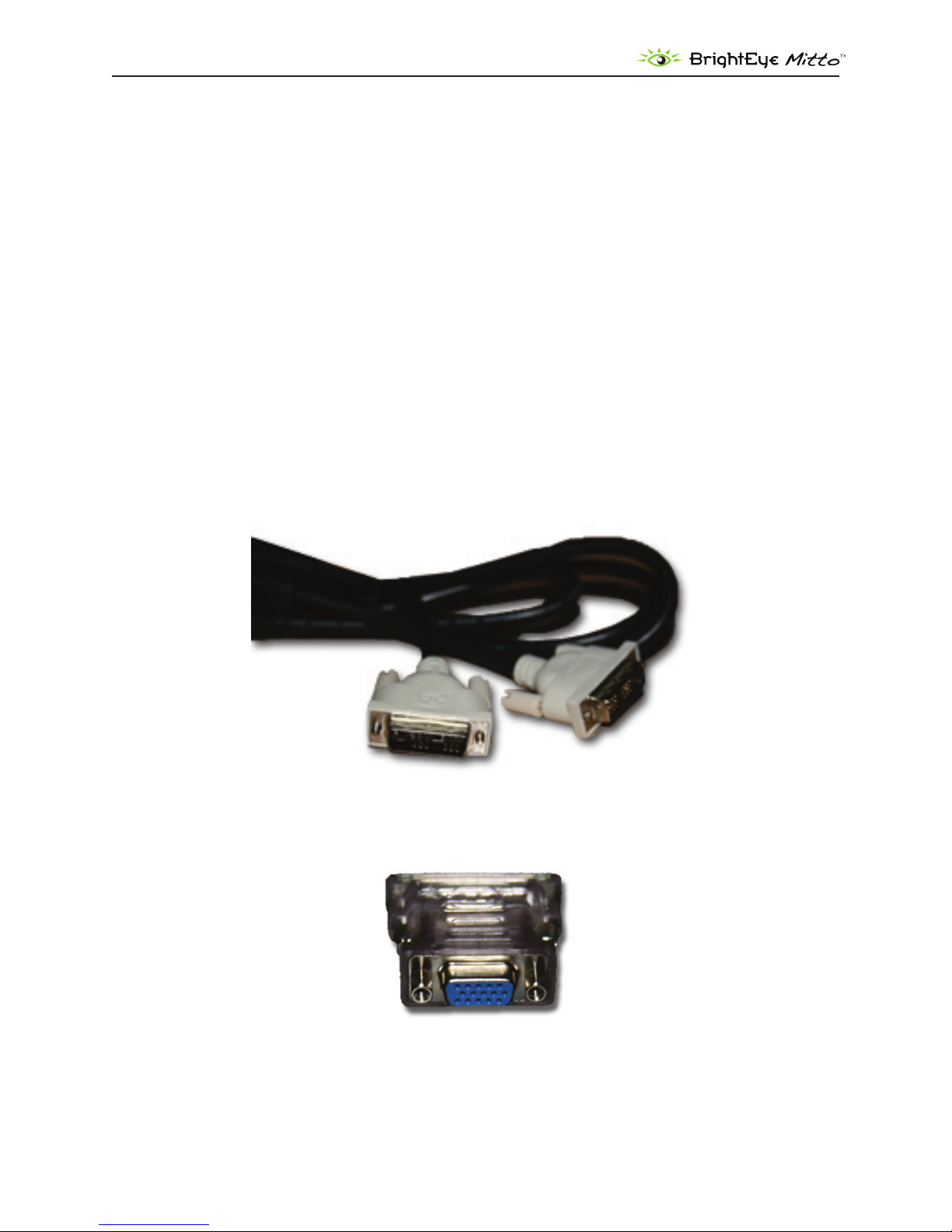
Mitto’s DVI/VGA Input and the DVI/VGA Loop Out use DVI-I (integrated) connectors which provide
both digital and analog connectivity. The larger group of pins are digital while the four pins on the
right are analog. Included with every Mitto are two 15-pin, VGA-to-DVI adapters for use in legacy
installations.
SDI Out 1 and 2 BNCs output SD SDI, 1.5 Gb/s HD SDI, or 3 Gb/s HD SDI video. The output only
includes the portion of the computer screen that you have selected with Mitto. Mitto upconverts or
downconverts the signal depending on how much of the computer video you select and the output
standard you select.
The Composite Out BNC provides composite video out when SD is selected on the SDI outputs. If HD
is selected on the SDI outputs then the composite out BNC outputs black. Alternately, the Composite
Out BNC can be set to output AES audio with a control in BrightEye PC/Mac software.
Audio
Mitto has four audio sources to draw from: analog audio in, AES audio in, audio coming in along with
an HDMI input, and an internal tone generator.
AES digital audio or analog audio can be fed from the computer’s headphone out or line out into
Mitto’s audio input. The audio input is an 1/8 inch stereo mini-jack that goes to a stereo analog-todigital converter with two AES receivers which are followed by two sample rate converters. Two
channels of analog audio or four channels (two streams) of AES digital audio are supported on this
input.
If an HDMI input is used, 8 channels of embedded audio may be present.
There is also a tone generator. When Mitto’s internal color bars are turned on, there will be bars and
tone on the output.
The built-in audio mixer provides for level adjustment, channel tie, and output assignment controls
for up to four channels of output. If you use the audio control on Mitto’s front panel, the slider controls
www.ensembledesigns.com
BrightEye Mitto - Page 6

DVI/VGA to 3G/HD/SD Scan Converter User Guide
will automatically tie together.
The audio appears in the embedded SDI outputs and, if desired, can also be output as AES on the
Composite Out BNC.
RS-232 and GPI Control
Mitto’s RS -232/GPI port can be used with third-party control and automation systems. GPI and RS-232
are supported simultaneously. Additionally, the Ensemble Designs Avenue GPI control panel (part
number XYCP) can be used with BrightEye Mitto™.
www.ensembledesigns.com
BrightEye Mitto - Page 7

DVI/VGA to 3G/HD/SD Scan Converter User Guide
VITC Inserter
Sync
Separator
ScH Phase
10M Input
Timecode
Generator
DDR2 Memory
HD/SD
Serializer
Gain &
Mixing
RGB to YCrCb
Colorspace
Conversion
Frame
Synchronizer
Composite
Encoder
&
DAC
Audio
Source
Select
VITC
Detect
DVI/HDMI
Receiver
Audio
Embedder
Audio
Delay
AES
Encoder
Black Gen
VGA/RGB
A to D
AES Rcvr
AES Rcvr
Stereo ADC
TCXO
Internal
Precision
Standard
Reference Input
Composite, TLS, 10Mhz
Cpst/AES Output
Composite NTSC/PAL
or AES Audio
SDI Video Output
3G/HD/SD
DVI-I Input
Digital or Analog RGB
DVI-I Loop Out
EDID/DDC
Processing
SRC
SRC
SRC
DVITC
AT C
Inserter
USB
RS-232
Audio In
(mini-jack)
External
Control
Clock
Generation
Raster Scaling
Pixel Filtering
Progressive to
Interlace Conversion
Micro Processor
&
Control Systems
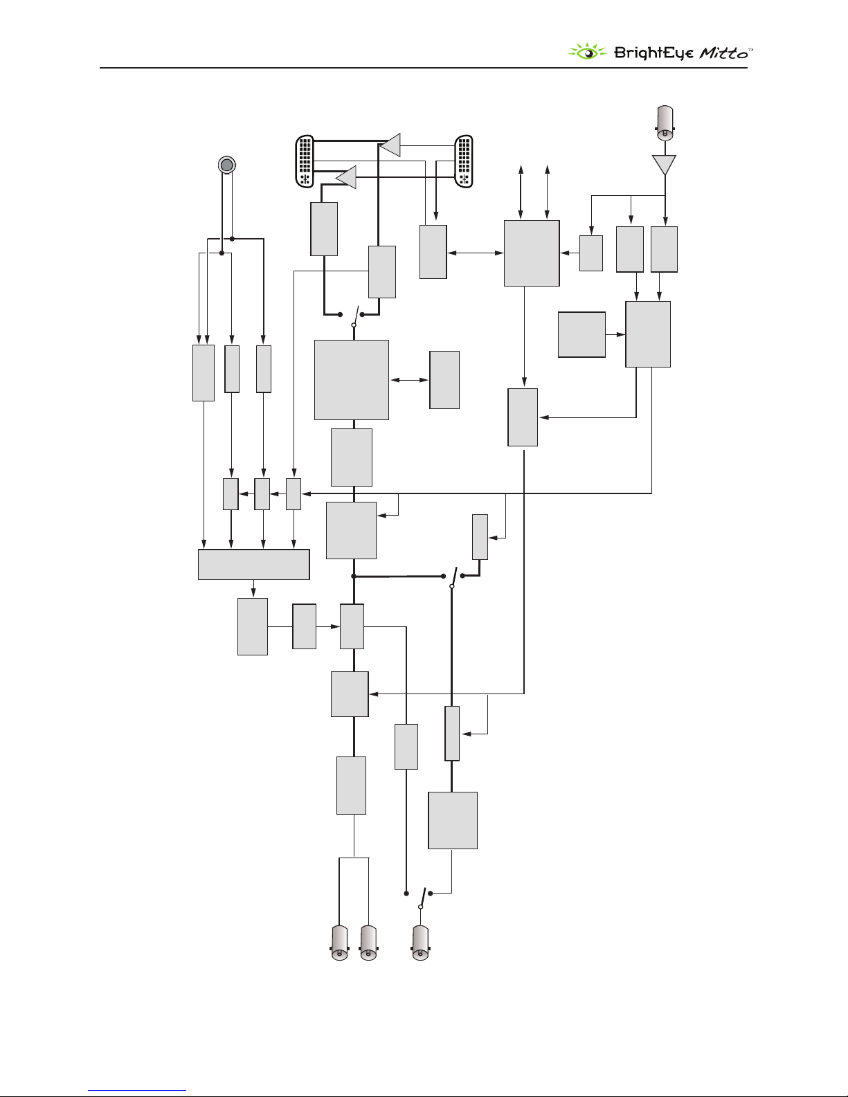
BLOCK DIAGRAM
For your reference, see the functional block diagram on this page and the following page. The diagram
appears twice, rst in a portrait view, then larger as a landscape view.
BrightEye Mitto Functional Block Diagram, Portrait View
www.ensembledesigns.com
BrightEye Mitto - Page 8
VITC Inserter
Sync
Separator
ScH Phase
10M Input
Timecode
Generator
DDR2 Memory
HD/SD
Serializer
Gain &
Mixing
RGB to YCrCb
Colorspace
Conversion
Frame
Synchronizer
Composite
Encoder
&
DAC
Audio
Source
Select
VITC
Detect
DVI/HDMI
Receiver
Audio
Embedder
Audio
Delay
AES
Encoder
Black Gen
VGA/RGB
A to D
AES Rcvr
AES Rcvr
Stereo ADC
TCXO
Internal
Precision
Standard
Reference Input
Composite, TLS, 10Mhz
Cpst/AES Output
Composite NTSC/PAL
or AES Audio
SDI Video Output
3G/HD/SD
DVI-I Input
Digital or Analog RGB
DVI-I Loop Out
EDID/DDC
Processing
SRC
SRC
SRC
DVITC
AT C
Inserter
USB
RS-232
Audio In
(mini-jack)
External
Control
Clock
Generation
Raster Scaling
Pixel Filtering
Progressive to
Interlace Conversion
Micro Processor
&
Control Systems
DVI/VGA to 3G/HD/SD Scan Converter User Guide
BrightEye Mitto Functional Block Diagram, Landscape View
www.ensembledesigns.com
BrightEye Mitto - Page 9

DVI/VGA to 3G/HD/SD Scan Converter User Guide
APPLICATIONS
BrightEye Mitto™ provides the best way to output computer material to video. Possible applications
include using YouTube material in a news broadcast, showing nancial data from a website on a
TV program, displaying viewer emails on a morning talk show, and taking radar information from a
computer into a master control switcher for on-air use.
There are several common ways to connect BrightEye Mitto™ in your facility. A typical connection uses
a computer monitor and a video monitor.
BrightEye Mitto™ can be used in your facility in many ways:
With a computer monitor and video monitor.•
With a laptop.•
Without a computer monitor. •
Mitto can be controlled exclusively from the Mitto front panel.•
Mitto can also be controlled from BrightEye PC/Mac control software.•
Mitto has a serial and GPI interface for control through third party equipment such as an •
automation system.
Getting Started
There are three steps to setting up your Mitto, as listed below. Details are provided on the following
pages.
If you plan to use BrightEye PC or Mac control software, install it on your computer. 1.
Connect Mitto to your computer and video equipment. 2.
Set the resolution of your computer’s monitor to the best possible resolution, such as 1920x1200 3.
or 1920x1080.
Installing BrightEye Software
BrightEye PC/Mac software oers complete control of BrightEye Mitto™. Timing, proc controls, video
formats and more can be controlled with the included software. The software allows you to use
your mouse to click and drag over the specic portion of computer video that you want to output.
However, BrightEye PC/Mac software is not required as the Mitto front panel controls are intuitive and
provide extensive control. You can choose what type of control is best for your facility.
To install software on a PC, insert the CD into your computer, double click on the BrightEye PC icon
and follow the prompts.
To install software on a Mac, insert the CD into your computer, then drag the BrightEye Mac icon into
your Applications folder.
The latest version of BrightEye PC and BrightEye Mac can be downloaded at http://brighteyemitto.com
www.ensembledesigns.com
BrightEye Mitto - Page 10

DVI/VGA to 3G/HD/SD Scan Converter User Guide
Connecting Mitto
See the “REAR CONNECTORS” section starting on page 14 for more information about the rear
connectors, cables and adaptors used for Mitto.
Start with your computer and monitor turned o. •
Connect a USB cable from your PC or Mac computer to the Mitto. •
Connect the Mitto’s DVI/VGA Loop Out connector to the computer monitor’s input. •
Connect the computer’s monitor output to the Mitto DVI/VGA Input connector. •
Connect the Mitto’s SDI Out or Composite Out BNC to a video monitor or destination. •
If using audio, connect the computer’s audio output to the Mitto’s Audio In. •
If desired, connect your reference signal to the Ref In. Mitto’s output is genlocked and fully •
timeable to this reference. Alternately, Mitto can be used without a reference.
Connect power to the Mitto. •
Turn on the computer and monitors. •
Cable Key
USB
DVI
Audio
SDI Video
www.ensembledesigns.com
BrightEye Mitto - Page 11

DVI/VGA to 3G/HD/SD Scan Converter User Guide
Conguring Mitto and Your Computer Monitor Resolution
Set the resolution of your computer monitor using the Display Control Panel.
PC Users
From the Start menu, go to the Control Panel and double-click Display to bring up the Display
Properties window.
Click the Settings tab.
From the Screen resolution control, select a resolution. For the best video output from BrightEye
Mitto™, select the highest available resolution on the computer. For HD applications, 1920x1200
or 1920x1080 is preferred. Alternately, you could choose 1024x768. 1920x1200 is the maximum
resolution that Mitto accepts.
www.ensembledesigns.com
BrightEye Mitto - Page 12

DVI/VGA to 3G/HD/SD Scan Converter User Guide
Mac Users
From the Apple Menu, select System Preferences. The System Preferences window displays.
The Mac System Preferences window
Select Displays. A window opens for each monitor attached to your computer. The computer sees
Mitto as a monitor. Its name will be either BE Mitto DVI or BE Mitto VGA.
From the Resolutions control, set the resolution sent to the Mitto. For the best video output from
BrightEye Mitto™, select the highest available resolution on the computer. For HD applications,
1920x1200 or 1920x1080 is preferred. Alternately, you could choose 1024x768. 1920x1200 is the
maximum resolution that Mitto accepts.
www.ensembledesigns.com
BrightEye Mitto - Page 13

DVI/VGA to 3G/HD/SD Scan Converter User Guide
When using VGA
When a VGA signal is fed to Mitto, you must choose a VGA resolution using the VGA Resolution control
from the Input menu in the BrightEye software. When DVI (digital) is used, Mitto auto senses the
resolution and you do not need to indicate the resolution on the VGA Resolution control.
Verifying Resolution Settings for PC and Mac
To make sure that your chosen resolution is being delivered to the Mitto correctly:
From the BrightEye control software’s Input menu, look at the "Input Width" and "Input Height"
indicator display of the Mitto.
Make sure that these values match what you have selected in the Display control panel. Some
video cards may scale their output at some resolutions. You may need to experiment with dierent
resolutions to nd one that works properly.
EDID
In many installations Mitto will sit between your PC and monitor. The default conguration for Mitto is
that it reports its own EDID to your computer.
Most DVI and HDMI monitors support HDCP encryption which will not work with BrightEye Mitto™.
If the computer handshakes with the computer monitor and HDCP is enabled, the encryption will
cause the Mitto output to be disabled or distorted. For this reason Mitto provides its own EDID to the
computer.
www.ensembledesigns.com
BrightEye Mitto - Page 14
DVI/VGA to 3G/HD/SD Scan Converter User Guide
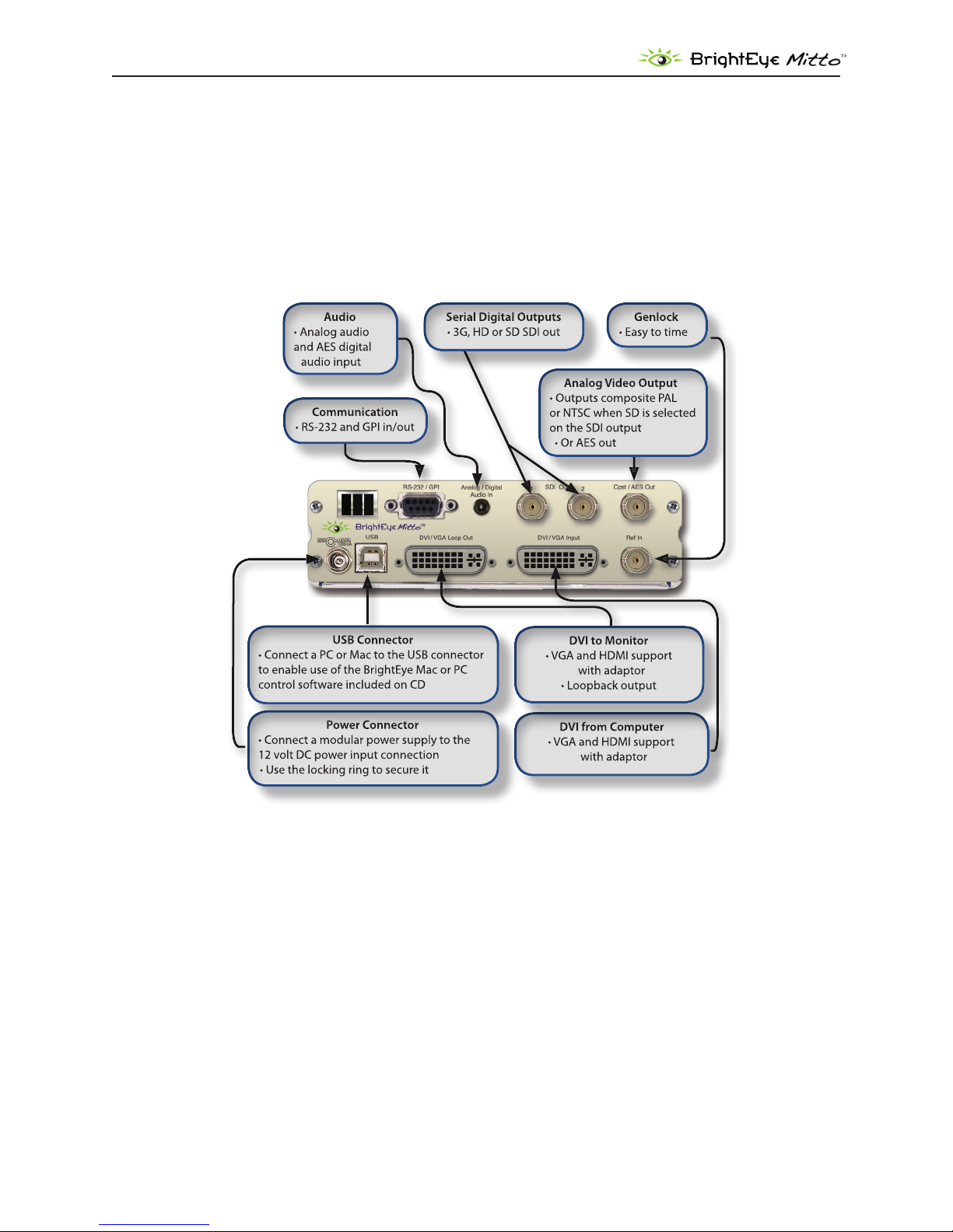
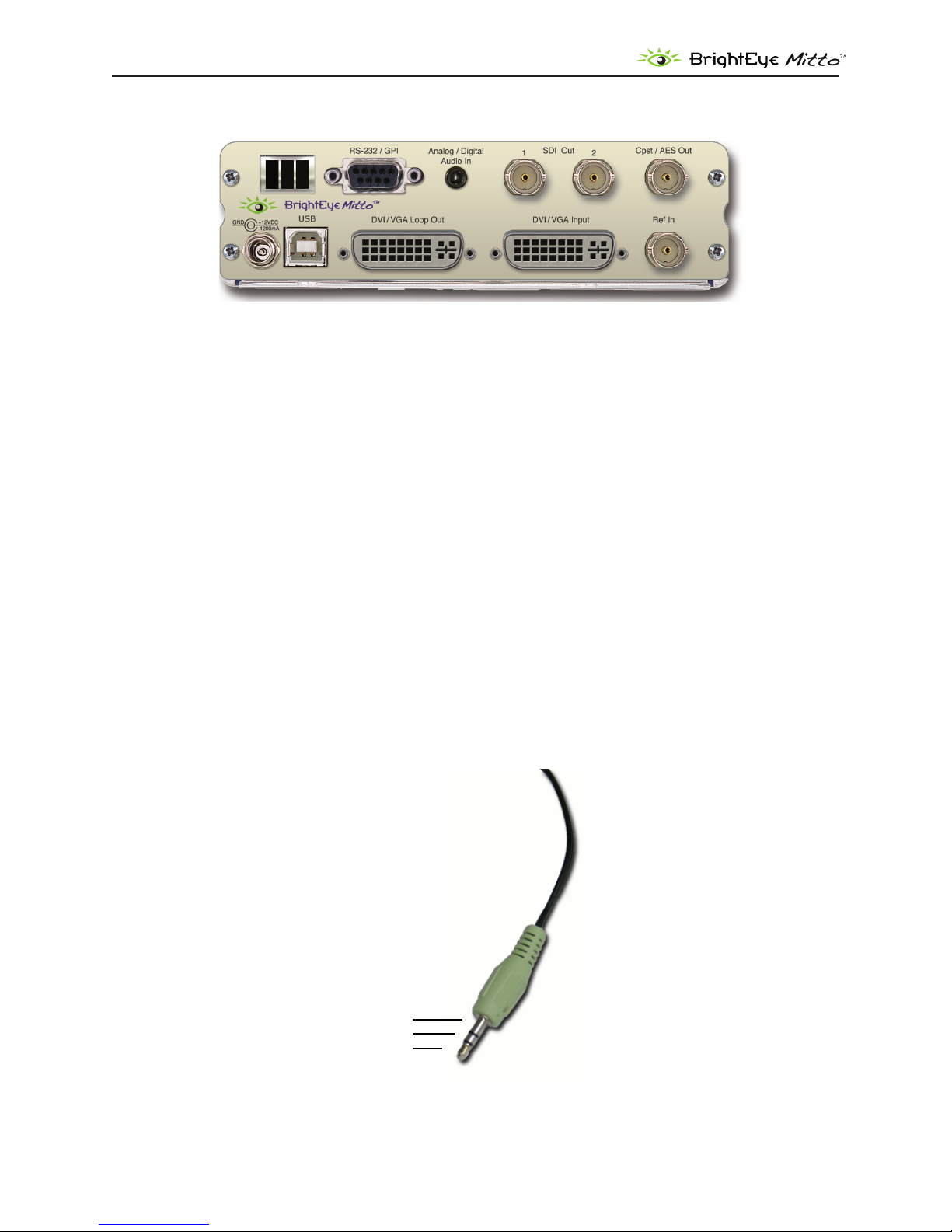
REAR CONNECTORS
All connections to the BrightEye Mitto™ are made on the rear of the unit. Refer to the illustration below
for a snapshot reference of the rear connectors. A more detailed explanation of the rear connectors
with illustrations of cable connectors follows.
www.ensembledesigns.com
BrightEye Mitto - Page 15
DVI/VGA to 3G/HD/SD Scan Converter User Guide
Left
Right
Ground
RS-232 / GPI
The RS-232/GPI port can be used with third-party control and automation systems. GPI and RS-232 are
supported simultaneously. Additionally, the Ensemble Designs Avenue GPI control panel (part number
XYCP) can be used.
Audio/Digital Audio In
Analog Stereo: This is a two-channel input using a standard 1/8” mini-jack. It can be connected directly
to the analog audio line level output of a tower or laptop computer. If your computer does not have a
line level output, you can also use the headphone output of the computer. The level of this output can
depend upon several settings in the computer. The Windows or Mac OS X audio control panels as well
as the specic application software will both aect the output level. The general recommendation is to
set both of these controls to 80% of their maximum value.
AES or S/PDIF Digital Audio: Mitto can accept four channels of digital audio. A pair of digital audio
channels is carried in an AES or S/PDIF bit stream. Mitto can receive digital bit streams on the same
audio mini-jack connector. The channels 1/2 bit stream is received on the “left” input of the connector,
and the channels 3/4 bitstream is received on the “right” input of the connector. These inputs are
processed through sample rate converters which accommodate sampling frequencies from 44.1 to
96 KHz.
www.ensembledesigns.com
BrightEye Mitto - Page 16
DVI/VGA to 3G/HD/SD Scan Converter User Guide
SDI Out 1 and 2
The SDI Out 1 and 2 BNCs output the same signal on both BNCs (except when 3 Gb/s Level B is
selected.) Choices are SD SDI, HD SDI, or 3 Gb/s HD SDI video. Connect to a video destination such as a
router, production switcher, or broadcast monitor.
Composite Out
This analog video output BNC provides composite PAL or NTSC and follows the SD output when SD
is selected on the SDI output. When HD is selected for the SDI output, the composite output provides
black.
Ref In (Reference In)
The Ref In BNC accepts 1 V P-P Composite Video PAL, NTSC, or HD Tri-Level Sync reference. The video
outputs will be zero-timed to the reference, or you can adjust the output timing to anywhere in the
television frame. A reference is not required for operation.
www.ensembledesigns.com
BrightEye Mitto - Page 17
DVI/VGA to 3G/HD/SD Scan Converter User Guide
Power Connection
Connect the modular power supply to the 12-volt DC power input connection on the far left of the
unit. Use the locking ring to secure it. If you don’t have the power supply already, contact Ensemble
Designs to purchase one.
USB Connector
Connect the USB port to a PC or Mac running BrightEye software for more comprehensive control,
diagnostics, and upgrades to the unit. BrightEye PC/Mac Control application software is included on
CD that came with your Mitto, or the application can be downloaded at: www.brighteyemitto.com.
www.ensembledesigns.com
BrightEye Mitto - Page 18
DVI/VGA to 3G/HD/SD Scan Converter User Guide
DVI/VGA Input
Connect the DVI output of your computer monitor to Mitto’s DVI/VGA input. Mitto’s DVI/VGA Input
and the DVI/VGA Loop Out use DVI-I (integrated) connectors which provide both digital and analog
connectivity. The larger group of pins are digital while the four pins on the right are analog.
If your computer has VGA out, use the VGA-to-DVI adaptor that is included with your Mitto.
HDMI is supported with an HDMI-to-DVI adaptor (not included). The HDMI standard provides for
carriage of both digital video and audio. Mitto supports two channels of digital audio from HDMI
sources.
DVI/VGA Loop Out
If desired, connect the DVI/VGA Loop Out to the DVI input of your computer monitor.
If your computer monitor has VGA in, use the DVI-to-VGA adaptor that is included with your Mitto.
HDMI is supported with a DVI-to-HDMI adaptor.
www.ensembledesigns.com
BrightEye Mitto - Page 19
DVI/VGA to 3G/HD/SD Scan Converter User Guide
CONFIGURATION AND CONTROL
Control and operation of the BrightEye Mitto™ is performed from the front panel, the BrightEye
Control application, or thru the RS-232/GPI port. Mitto’s front panel controls provide extensive
control for screen selection and most of the video and audio parameters. Some control settings and
parameter choices are available only with BrightEye PC or Mac software. These parameters cannot be
monitored from the front panel.
Adjusting Parameters from the Front Panel
The six buttons on the right side of the Mitto’s front panel are used to navigate the controls. If you are
familiar with our BrightEye products, you will notice that the Mitto has three additional buttons.
Prev and Next navigate through the various controls, such as Aspect and Position. When a control is
selected its LED blinks on and o. Arrows change values for the control you selected.
Pressing the Right Arrow or Left Arrow advances the selection within a given section of parameters,
or increases (Right Arrow) or decreases (Left Arrow) the value of a selected parameter.
Resetting to Default Values
Holding the Left Arrow and Right Arrow buttons at same time restores the selected control to its
default value. For example, with the Position control selected, pressing the Left Arrow and Right
Arrow buttons at the same time will cause the horizontal Position value to be restored to its default
value, which is all the way to the left side of the computer monitor. Similarly, with the Position control
still selected, holding the Up Arrow and Down Arrow buttons at the same time restores the vertical
Position to be restored to its default value, which is at the top of the computer monitor.
The front panel LED indicators light green when in their default values, and they light orange when
values other than the default are selected.
Press and Hold to Accelerate Movement Controls
The arrow buttons have a hold function. The behavior of pressing and holding an arrow button
depends on which control you have selected. For example, with the Position control selected, if you
press and hold the Right Arrow button, the screen selection will move at an increasing rate to the
right across the computer monitor.
www.ensembledesigns.com
BrightEye Mitto - Page 20

DVI/VGA to 3G/HD/SD Scan Converter User Guide
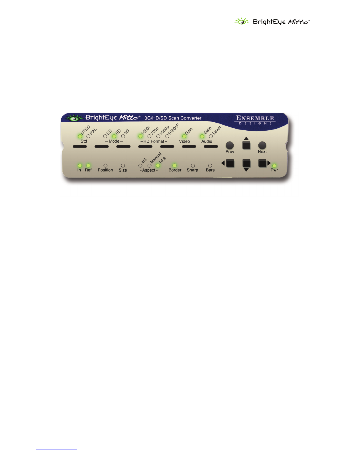
Front Panel Controls and Indicators
Status Indicators
The following status indicators are provided on the front panel:
Std (Standard): The currently selected output standard (NTSC or PAL) will illuminate green. This is also
a control to choose the standard. You can choose to operate in the NTSC standard, which would be
59.94 elds or 29.97 frames per second, or the PAL standard, which would be operating at 50 Hz.
Mode: The currently selected mode (SD, HD, 3G) illuminates green. Choose between SD (standard
denition), HD (high denition), and 3 Gb/s (high denition). Currently, HD is the most commonly used
high denition signal.
HD Format: The currently selected HD Format is illuminated green. Choose between 1080i, 720p,
1080p, or 1080sF.
Video Gain: The video gain control adjusts the overall gain level for the video output. If you want
more controls than just the overall level, see the Proc tab in the complete control system accessible
by using the BrightEye PC or BrightEye Mac software that connects to the USB port on the back of the
Mitto.
Audio
Gain: Audio gain control used to set the level. It displays green when the control is at unity. It displays
orange when the control is set higher or lower than unity.
Level: The Audio level indicator reects the level of the audio being routed to output channels 1 and 2.
If the level is within the peaking threshold, it displays green. The indicator displays yellow if the level is
approaching the peaking threshold, and red if it exceeds the peaking threshold.
In (Input): The Input indicator will light green if you have a valid DVI or VGA input connected from a
computer.
Ref (Reference): The Reference indicator will light green when a valid reference is present and locked.
Position and Size are used to select the portion of the computer screen to be scan converted and
output to either standard denition or high denition video. Position determines the upper left
corner of the region you are going to output, while Size determines the lower right corner of the
region for output.
When the Position LED is blinking, adjust the position of the upper left corner of the selection. Use the
four arrows to control position. Press and hold for faster movement.
Short cut: Press and hold left and right arrows at the same time to reset the H position to default
values. Press and hold up and down arrows to reset V position.
Size determines the lower right corner of the region for output.
When the Size LED is blinking, adjust the position of the lower right corner of the selection. Use the
four arrows to control size.
www.ensembledesigns.com
BrightEye Mitto - Page 21

DVI/VGA to 3G/HD/SD Scan Converter User Guide
Short cut: Press and hold up and down (or right and left) arrows at the same time to reset to maximum
possible size.
Maximum Screen Selection Shortcut
To maximize the screen selection instantly, hold down the Up, Left, and Right Arrow buttons
simultaneously while Position or Size are active. Within the constraints of the currently selected
aspect ratio, Mitto will instantly maximize the screen selection on the computer monitor.
Aspect lets you set a xed aspect ratio of the portion of the screen you are selecting. 16:9 aspect ratio
is appropriate for high denition. 4:3 aspect ratio is appropriate for standard denition. With Manual
selected, you can choose any arbitrary aspect ratio. Pillar boxes or letter boxes are added automatically
so that the output matches the output standard selected.
The Border control lets you adjust a black border around the selected video as it appears on the high
denition or standard denition video output.
Sharp: The Sharpness control adjusts the lters in Mitto. You can adjust the sharpness to optimize how
particularly challenging pieces of video are ltered prior to output.
Bars: Turn color bars on or o. Turn bars o for normal video operation.
Pwr (Power): The power indicator illuminates green when the BrightEye unit has power and the
internal voltage regulator is functioning correctly.
USING THE BRIGHTEYE CONTROL APPLICATION
The BrightEye PC and BrightEye Mac applications included on CD-ROM are designed to allow you to
congure and control the BrightEye Mitto from a personal computer. Instructions for installing and
using this software application are given in the PDF manual on the CD-ROM.
Software version requirement
BrightEye PC or BrightEye Mac version 2.0 or later is required.
If the BrightEye Mitto is connected to a computer running this software, the menus described in the
following pages are available for controlling and monitoring the unit.
www.ensembledesigns.com
BrightEye Mitto - Page 22
DVI/VGA to 3G/HD/SD Scan Converter User Guide
Conguration and Setup
The conguration and setup process will walk you through the following three menus as these are
most useful for conguring your system prior to use:
Output Menu1.
Audio Conguration Menu2.
Input Menu3.
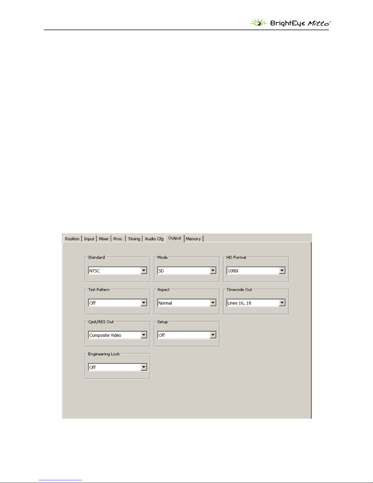
Output Menu
The three controls along the top of the Output menu (Standard, Mode, HD Format) are used to
determine Mitto’s output standard. Regardless of what type of input is fed into Mitto, whether it is DVI
or VGA, the output will match the conguration selections you have made.
The Standard, Mode, and HD Format controls are also accessible on the Mitto front panel.
Standard: Select NTSC or PAL.
Mode: Select SD, HD, or 3G.
HD Format: If working with HD, select 1080i, 720p, 1080p, or 1080sF.
www.ensembledesigns.com
BrightEye Mitto - Page 23

DVI/VGA to 3G/HD/SD Scan Converter User Guide
Test Pattern: When Mitto’s internal color bars are turned on, there will be bars and tone from Mitto’s
internal tone generator on the output. Turn bars on or o. Turn bars o for normal video operation.
Aspect: The Aspect ratio control is ordinarily left in Normal. Mitto guarantees that the aspect ratio of
the selection you have made on the computer will be output to video with the proper aspect ratio.
Circles will stay circles.
There may be times when you would choose to override normal aspect ratio. If you select Anamorphic,
it will allow you to select a region on the input side that is the output of the computer and pin the
corners of that region to the output space. In that case, depending on how you have made your
selection, circles may not be circles. But in certain cases, that may be exactly what you are intending.
Note: If you are experiencing issues with maintaining the correct aspect ratio, please see the
Troubleshooting section on page 38 for recommendations.
Timecode Out: Mitto will generate timecode in ATC (or ancillary timecode format) when running in
SD, and in DVITC (or digital vertical interval timecode) when running in HD. You can turn the timecode
o. When you turn it on use this control to select which pair of lines it will appear on for an SD signal.
Any selection, such as Lines 16 and 18, will work for an HD signal.
Composite/AES Out: Select between Composite Video or AES Audio for the Cpst/AES out BNC.
Setup: The Setup control is used to turn o and on 7.5 IRE of setup or black oset in the analog
composite output for NTSC applications.
Engineering Lock: When the Engineering Lock is on, it locks, or grays out, the Standard, Mode and HD
Format controls on the Output menu; it also locks all the controls on the Timing menu (vertical timing,
horizontal timing, and ne phase timing).
www.ensembledesigns.com
BrightEye Mitto - Page 24

DVI/VGA to 3G/HD/SD Scan Converter User Guide
Audio Conguration Menu
Audio Input
Mitto has three possible audio inputs.
The rst type of audio input is analog. There is an 1/8 inch mini-jack in the back of Mitto that will 1.
accept two channels of stereo analog audio. When the Analog input is selected, the left channel is
assigned to Input 1 and the right channel is assigned to Input 2. Mixer Inputs 3 and 4 are not used.
The second type of audio input is AES. If you choose AES, the 1/8 inch mini-jack in the back of 2.
Mitto can accept two AES bitstreams (four channels), one on the “left” pin of the connector and
one on the “right” pin. When AES (or S/PDIF) is selected, the bit stream connected to the “left” input
will appear on Mixer Inputs 1 and 2, and the “right” bit stream will appear on Mixer Inputs 3 and 4.
The third type of audio input is through HDMI video coming in through the DVI port. The HDMI 3.
standard can support eight channels of digital audio. HDMI audio will appear on Mixer Inputs 1
and 2. If you select DVI, an HDMI source fed to the DVI connector will provide the audio into Mitto.
Mitto has two audio output capabilities.
The four channels of audio from the audio mixer can be embedded in the SD SDI or HD SDI output. 1.
Embedded audio travels with the digital video through cables, distribution amps, and routers
without the need for any additional wiring. The SDI standard allows 16 channels of embedded
audio, which is organized into four groups of four channels each. The four channel output from
Mitto ts into a single group. You can assign the audio to a specic group using the Embedding
control in the Audio Cong menu. This control also allows you to turn embedding o.
Mitto can also output two channels of digital audio as an AES bit stream (just like the input 2.
capability). This AES output shares a connector with the Composite Video output. The Cpst/AES
Out control in the Output menu congures this connector to output either Composite video, AES
channels 1 and 2, or AES channels 3 and 4.
Embedding
You can control how audio is being embedded into the HD or SD SDI output. If Embedding is turned
O, no audio will be embedded into the output. If you set it to Group 1, it will embed audio into
group 1 (channels 1, 2, 3 and 4).
Analog Reference Level
Use this control to select the nominal reference level for the analog inputs. Mitto’s analog audio
input is unbalanced which is often used with -10 dBu analog reference level. Select the appropriate
reference level for your facility.
Digital Reference Level
Choose either -20dBFS or -18dBFS, relative to full scale.
www.ensembledesigns.com
BrightEye Mitto - Page 25

DVI/VGA to 3G/HD/SD Scan Converter User Guide
Peak Indicator
The nominal operating audio level indicator and peak audio indicator provide a way to monitor audio
levels at a glance. This controls allow you to set the amount of headroom that you wish to reserve
before the clipping or peak indicator illuminates. For example, if this control is set to 6 dB Headroom,
the peak indicator will not ash red unless the audio level exceeds the 6 dB Headroom point.
Audio Delay
Mitto has variable audio delay to help you keep lip sync correct. The delay can be adjusted from 0 to
1000 milliseconds (mSec).
In the 50Hz domain, there are 40 mSecs in a frame, and 33 mSecs in a frame in the 60 Hz or NTSC frame
rate domain.
www.ensembledesigns.com
BrightEye Mitto - Page 26

DVI/VGA to 3G/HD/SD Scan Converter User Guide
Input Menu
The Input menu is for selecting a reference source (external or internal) and monitoring reference
status indicators and input indicators.
Input Selection • – Defaults to DVI. Select VGA if needed. This control cannot be set from
Mitto’s front panel. Use BrightEye PC/Mac software to set this control to VGA if needed.
VGA Resolution• – When DVI is used this control does not need to be adjusted as Mitto
will auto sense the resolution. When a VGA signal is fed to Mitto, set the resolution of the
computer’s video monitor here.
Note: With a VGA signal, you must make sure that the resolution setting chosen from the VGA
Resolution control matches the resolution setting of the computer monitor. Otherwise, you
may see a blue screen.
Input Pres• – The Input Present status eld indicates whether there is an input present.
Input Width• – The Input Width eld indicates the width of the computer output in pixels.
Input Height• – The Input Height eld indicates the height of the computer output in pixels.
Ref Source• – Select either Internal Ref or Ext Ref.
Reference• – The Reference indicator shows what sort of reference signal is present.
Sync Lock• – The Sync Lock indicator reects the status of the Mitto being properly locked and
synchronized to the reference.
Timecode Ref• – The timecode comes from the reference input. This control allows you to
select which line of the black composite reference carries the timecode to Mitto. Lines 16 and
18 are typical choices.
www.ensembledesigns.com
BrightEye Mitto - Page 27

DVI/VGA to 3G/HD/SD Scan Converter User Guide
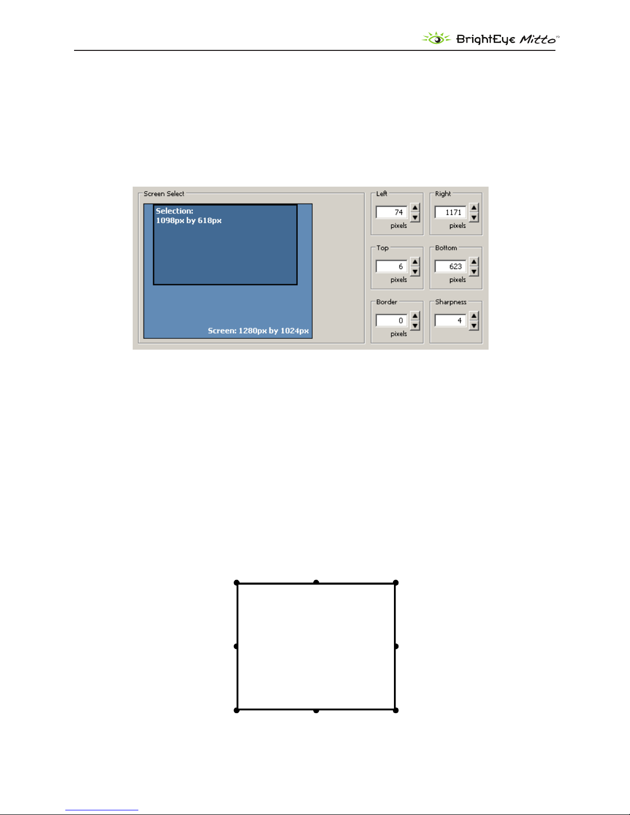
Position Menu
The Position menu is used to select a portion of the computer monitor display for scan conversion. It is
also used for selecting the Aspect Ratio, for creating a border and for setting the Sharpness control.
The Position menu includes a Screen Select window, indicating what portion of the computer monitor
output has been selected for scan conversion. The light blue region represents the entire computer
output screen. It indicates the resolution of the computer monitor in terms of pixel height and width.
In the example shown below, the resolution being used is 1280 by 1024. The highest resolution that
Mitto supports is 1920 by 1200.
The smaller rectangle, slightly darker blue, indicates the selected area or Selection. It shows not only
the size but also the position within the computer output that is being selected for scan conversion. In
the example shown below, the Selection is 1098 by 618 pixels.
The upper left corner of the Selection is the “Position Corner.” The Position arrow buttons act on the
location of the entire Selection relative to the Position Corner. For example, as the Position Corner
moves 20 pixels to the right, the entire Selection also moves 20 pixels to the right. Note that moving
the Position Corner does not change the Selection’s shape or size.
The lower right corner of the Selection is the “Size Corner.” The Size Corner can be moved relative to
the Position Corner. In contrast to moving the Position Corner, moving the Size Corner causes the
Selection’s shape or size to stretch or shrink.
The Position menu with controls for Position, Size, Aspect Ratio, the Screen
Select window, and the Border and Sharpness controls.
www.ensembledesigns.com
BrightEye Mitto - Page 28

DVI/VGA to 3G/HD/SD Scan Converter User Guide
Four ways to control Selection’s Position and Size
When controlling Mitto from the BrightEye PC or Mac application, the Position and Size can be 1.
adjusted through the Selection Tool, which is part of the BrightEye Mac or PC application. See
page 30 for more details about the Selection Tool.
A second way to control the Position and Size is through the 2. Position and Size arrow buttons in
the Position menu.
A third way is through the 3. Left, Right, Top and Bottom controls in the Position menu, located to
the right of the Screen Select window.
A fourth way to control the Position and Size is from the front panel of Mitto. With the Position or 4.
Size control selected on the front panel, you can use the Left Arrow, Down Arrow, Right Arrow
and Up Arrow buttons.
The four directional arrow buttons move the selection one pixel at a time for each click. Pressing
and holding down a button will accelerate the movement of the Selection. Notice that when
moving the Selection’s Position, the Selection remains the same size. Moving the Selection’s Size,
however, will change the size and shape of the Selection.
Maintaining Aspect Ratio
To adjust the size of the Selection, the upper left Position corner stays in the same position, but the
lower right corner of the selection moves with the Size control. With an aspect ration of 16:9 selected,
if you move the Size control to the right, it will make the Selection wider, and it will also make it taller
in order to maintain the 16:9 aspect ratio. If you use the Size control to raise the lower right corner, it
also pulls the right edge in to maintain the chosen aspect ratio. The aspect ratio of 4:3 works the same
way.
Using Manual Aspect Ratio
By selecting a manual aspect ratio, you can increase the width independently of the height. It is
possible to select an area that is much wider than can be shown on a 16:9 high denition display;
for example, a 1362 by 436 pixel selection. When this is output, Mitto automatically letter boxes the
content with a black region above and below so that the aspect ratio of the content will be correct.
Similarly, Mitto automatically pillar boxes the content as needed with a black region on either side to
maintain the correct aspect ratio for output when the selection is taller than the output aspect ratio
would normally allow.
www.ensembledesigns.com
BrightEye Mitto - Page 29

DVI/VGA to 3G/HD/SD Scan Converter User Guide
One Click to Move Selection to an Outside Edge
Clicking one of the smaller directional Position arrow buttons (with the perpendicular line) causes
the Selection area to move immediately to the outside edge of the direction chosen with one click.
Similarly, clicking the smaller down or right Size arrow buttons causes the Size of the Selection area
to move to an outside edge. However, clicking the smaller left or up Size arrow buttons minimizes the
size of the Selection.
Position Default Button – Clicking the Default button for Position immediately places the position of
the Selection area at the upper left corner.
Size Default Button – Clicking the Default button for Size immediately maximizes the size of the
Selection area within any aspect ratio contstraints, but does not change the Position of the upper left
corner of the Selection area.
Full Screen – Clicking the Full Screen button instantly maximizes the size of the Selection area. The
Position will be moved to the upper left corner while the Size will be maximized within any aspect
ratio constraints.
Border – Lets you adjust a black border pixel width around the selected video as it appears on the
high denition or standard denition video output.
Sharpness – The Sharpness control ranges from a minimum value of 1 up to a maximum value of 8.
This is a set of variable lters used to congure the processing through which Mitto is moving the
input video to the output. The mid-range setting of 4 is recommended as a good place to start.
www.ensembledesigns.com
BrightEye Mitto - Page 30

DVI/VGA to 3G/HD/SD Scan Converter User Guide
Selection Tool
The region of the computer screen that is inside the Selection Tool will be output to video.
To access the selection tool, click the Show Selection Tool button along the top tool bar in BrightEye
PC or Mac. The Selection Tool displays as a oating rectangle, oating over the top of everything else
running on the computer, including any graphics programs.
The Show Selection Tool button on the top toolbar of BrightEye PC
When you click the Show Selection Tool button, it toggles into the Hide Selection Tool button.
Similarly, when you click the Hide Selection Tool button, it toggles into the Show Selection Tool
button. Click the Hide Selection Tool on the toolbar to put the Selection Tool away.
Click and drag the Selection Tool to move and resize the selection for outputting to video. Aspect
ratio constraints apply to the Selection Tool in the same way that they apply to the Screen Selection
window in the Position menu.
Tip: If you have clicked the Show Selection Tool button but do not yet see it, click and hold the
Up arrow in the Size control to reduce the size of the Selection Tool. Once it is small enough, it will
become visible on the computer monitor. Clicking and holding the size Up arrow reduces the size of
the Selection Tool and brings it into view.
The Selection Tool shown oating over the computer monitor
www.ensembledesigns.com
BrightEye Mitto - Page 31
DVI/VGA to 3G/HD/SD Scan Converter User Guide
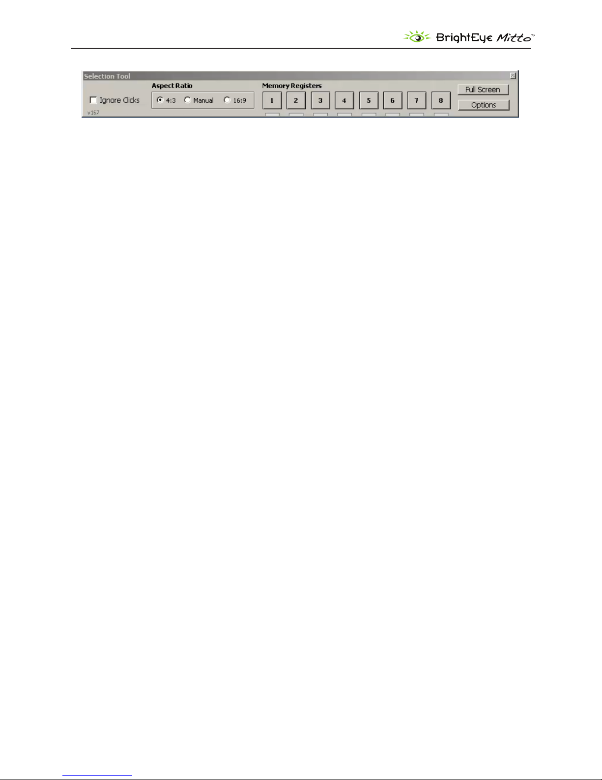
The Selection Tool oating toolbar
Selection Tool oating toolbar
When using the Selection Tool, it is accompanied by a Selection Tool oating toolbar. From this toolbar,
you can adjust the Aspect Ratio (4:3, Manual, or 16:9). The Memory Registers are also accessible for
saving and recalling position settings.
Ignore Clicks checkbox
Click the Ignore Clicks checkbox when you need to be free to interact and click on your computer
screen without in any way disturbing the position and size of the Selection Tool. When the Ignore
Clicks checkbox is selected, the color of the Selection Tool will brighten slightly.
Deselect the checkbox to restore interactivity with the Selection Tool.
Aspect Ratio
Select 4:3, Manual, or 16:9.
Memory Registers
Click Memory Registers to recall previously saved position settings. Save new position settings by
clicking and holding a Memory Register button until it turns green.
Full Screen button
The Full Screen button on this toolbar has the same function as the Full Screen button on the Position
menu. It is used for maximizing the size of the Selection Window, but within the constraints of the
selected aspect ratio and output settings.
Options button
Click the Options button to access a color palette tool for changing the color of the Selection Tool.
www.ensembledesigns.com
BrightEye Mitto - Page 32
DVI/VGA to 3G/HD/SD Scan Converter User Guide
Screen Select window
Note that the Screen Select window within the Position menu tracks the exact movement of the
screen selection (its position and size) within the context of the entire screen monitor resolution space.
This is shown by the location of the Selection in the Screen Select window.
The exact pixel dimensions (width and height) are also indicated.
The Screen Select window within the Position menu
Appearance of Selection Tool when in Manual Aspect Ratio
When Manual aspect ratio is selected, extra handles display on the Selection Tool to facilitate freely
changing its height and width independently. 16:9 and 4:3 aspect ratio constraints do not apply.
Notice the additional handles located in the middle of each side.
Moving Selection Tool: To move the Selection Tool without resizing it, click and drag directly on one
of the sides of the tool, not on a handle.
Resizing Selection Tool: To resize the Selection Tool, click and drag directly on any of the eight
handles of the tool. You can resize by clicking and dragging one of the handles on a side, or on a
corner.
www.ensembledesigns.com
The Selection Tool when the aspect
ratio is set to manual
BrightEye Mitto - Page 33
DVI/VGA to 3G/HD/SD Scan Converter User Guide
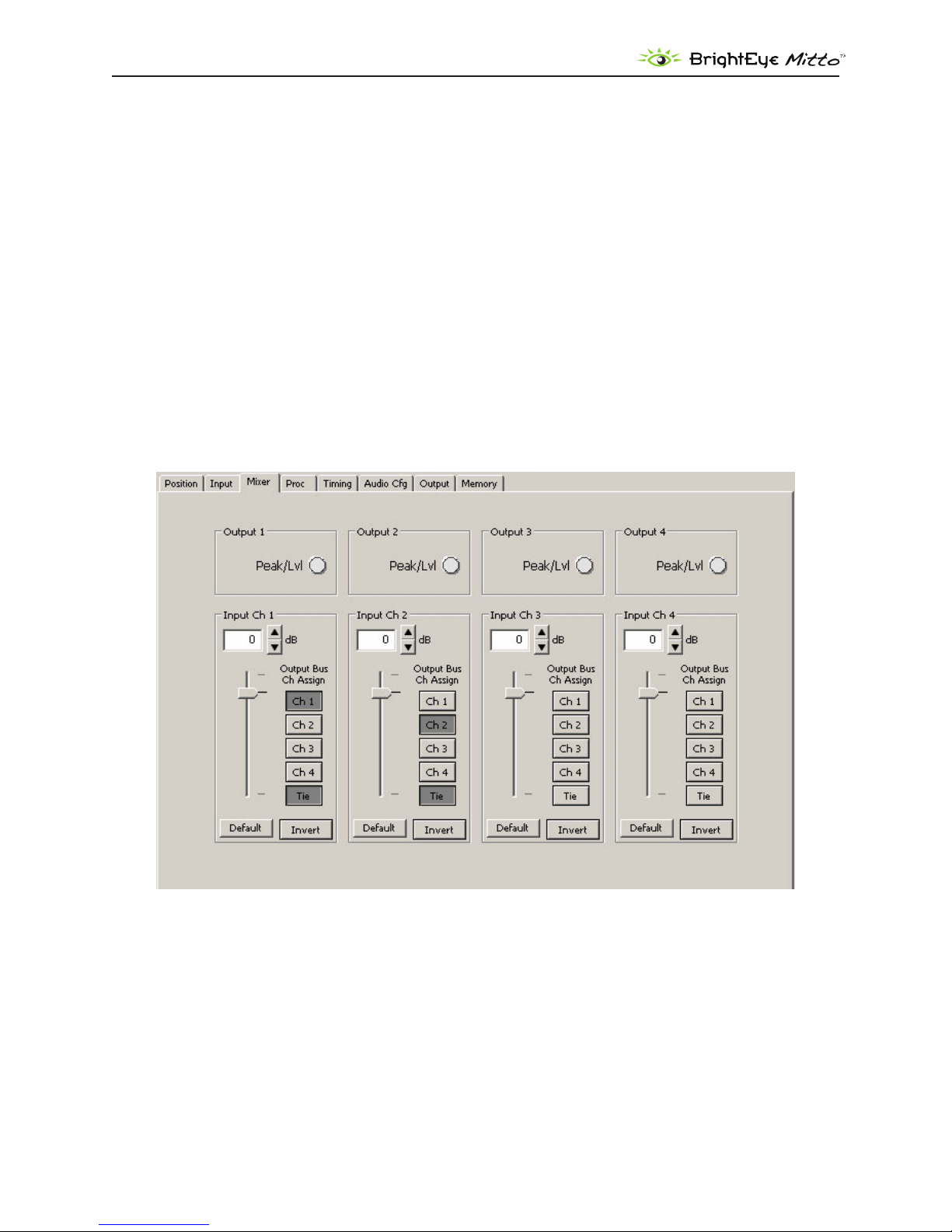
Mixer Menu
Mitto has a four-channel audio mixer with four inputs and four outputs. It allows you to adjust the
level of each channel independently. Any audio input can be assigned to any audio output.
If you have chosen analog audio as the input, which would be stereo, then you will have two input
channels: Input Channel 1 and Input Channel 2.
For example, you could route Input Channel 1 to Output Channel 1, Input Channel 2 to Output
Channel 2, Input Channel 3 to Output Channel 3, and Input Channel 4 to Output Channel 4.
Another conguration example would be to turn o Input Channels 3 and 4 by de-selecting the
Output Channel assignments, meaning that no Output Channels are selected for Input Channel 3 or
Input channel 4. Then route Input Channel 1 to Output Channel 1 and Output Channel 3, and Input
Channel 2 to Output Channel 2 and Output Channel 3. Now Channels 1 and 2 will have the same
original stereo content, and the Channel 3 will output a mono mix-down.
www.ensembledesigns.com
BrightEye Mitto - Page 34
DVI/VGA to 3G/HD/SD Scan Converter User Guide
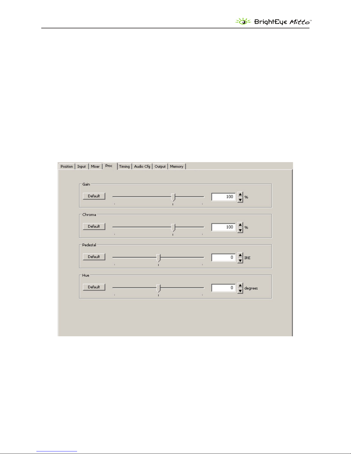
Proc Menu
The Gain control on the front panel is the same control as the Gain control in the Proc menu shown
below. The Proc menu oers more controls than the front panel’s Gain control.
The Proc amp menu oers a Gain control, which aects the overall video level. The Proc menu also
includes controls for the Chroma amplitude, the Pedestal or black level, and the Hue. This is an NTSCstyle Hue rotation. It can be used to make small adjustments in colorimetry.
The nominal settings for all of these controls would be 100% of overall Gain and Chroma; zero
adjustment to Pedestal and zero degrees of Hue rotation.
You can change these values by clicking and dragging on the slider control, by using the up and down
arrow buttons, or by entering values directly into the elds.
www.ensembledesigns.com
BrightEye Mitto - Page 35
DVI/VGA to 3G/HD/SD Scan Converter User Guide
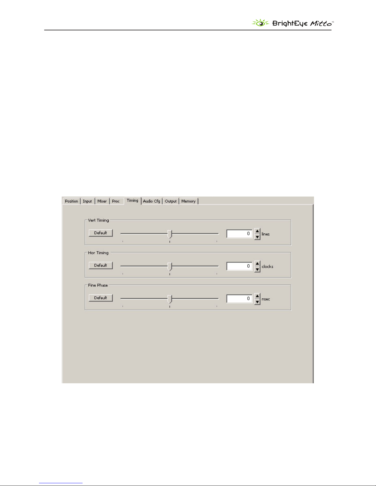
Timing Menu
The Timing controls adjust the timing of the HD SDI or SD SDI and composite output of Mitto with
respect to the reference input. If you set all three of the timing controls (Vertical, Horizontal, Fine
Phase) to zero, then Mitto’s output will be in exact time with the reference.
If, for example, you need to have Mitto’s output be one line early with respect to the reference in order
to auto-time properly into a production switcher, set the Vertical Timing to -1.
Vert Timing• – Set the vertical timing in lines. Use the slider controls or arrows to select a value,
or enter a value directly into the number eld.
Hor Timing• – Set the horizontal timing in clocks. Use the slider controls or arrows to select a
value, or enter a value directly into the number eld.
Fine Phase• – Set the ne phase timing in nsecs to color time the composite output. Use the
slider controls or arrows to select a value, or enter a value directly into the number eld.
www.ensembledesigns.com
BrightEye Mitto - Page 36
DVI/VGA to 3G/HD/SD Scan Converter User Guide
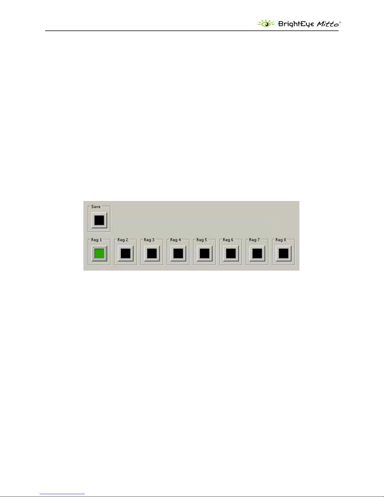
Memory Menu
The Memory menu provides access to a set of memory registers used to cut or switch between up to
eight dierent screen selection settings. Each memory register can save position, size, aspect ratio,
border, and sharpness settings. Clicking a saved memory register instantly switches the position
and size, the aspect ratio, border and sharpness to the saved settings associated with that particular
memory register.
To save settings to a memory register
Select a desired position and size, aspect ratio, border size, and sharpness settings. 1.
From the Memory menu, click 2. Save, then click Register 1. The Register 1 button turns green,
indicating that it has saved the screen selection settings.
To save additional memory registers, repeat the above procedure, except click 3. Register 2 after
clicking Save to create a second, Register 3 after clicking Save to create a third, and so forth. Note
that the last memory register to be saved or recalled will be green.
www.ensembledesigns.com
BrightEye Mitto - Page 37

DVI/VGA to 3G/HD/SD Scan Converter User Guide
TROUBLESHOOTING
There is no output signal, and/or the selection tool is not behaving as
expected
Recommendation: Make sure that the resolution settings of Mitto and the computer match one
another. Set the resolution of your computer monitor to the highest possible resolution. For best
results, choose one of these resolutions:
1920 x 1080 •
1920 x 1200 •
1024 x 768 •
Then use Mitto’s front panel or BrightEye Mac/PC software to set Mitto to the same resolution.
If you have trouble with using a resolution setting such as 1680 x 1050 or 1280 x 800, try one of the
above listed resolutions instead.
For VGA, choose the highest resolution that is available on both your computer and on the BrightEye
Mac/PC software Input menu from the VGA Resolution pull-down selector.
Aspect ratio is not being maintained correctly
Recommendation: Turn o scaling on your computer’s graphics card. All scaling should be performed
by BrightEye Mitto to ensure pixel size and shape are maintained properly.
If the picture being output by Mitto is not maintaining its correct aspect ratio (for example, a circle is
egg-shaped), check your computer’s graphics card settings and turn o any scaling that the computer
graphics card may be applying. Look for a tab that controls your graphics card. It may be referred to
as something other than “scaling” such as “modify” depending on which controls are provided by the
specic graphics card in your computer.
Mitto reports a dierent resolution than the settings you have applied to
your computer
Recommendation: Turn o scaling on your computer’s graphics card. All scaling should be performed
by BrightEye Mitto to ensure pixel size and shape are maintained properly.
Note: This applies to DVI only as Mitto detects the resolution of a DVI or HDMI signal but
cannot detect the resolution of a VGA signal.
If you have set your computer’s resolution to a certain value but Mitto reports a dierent resolution
(for example, you have set your computer to 1920 x 1080 but Mitto is reporting 1680 x 1050), the
graphics card may be overriding the resolution settings you have selected on your computer.
www.ensembledesigns.com
BrightEye Mitto - Page 38

DVI/VGA to 3G/HD/SD Scan Converter User Guide
Check your computer’s graphics card settings and turn o any scaling that the computer graphics card
may be applying. Look for a tab that controls your graphics card. It may be referred to as something
other than “scaling” such as “modify” depending on which controls are provided by the specic
graphics card in your computer.
I do not understand how to congure Mitto to work with a laptop
To congure BrightEye Mitto to work with a laptop, set the laptop for use with an external monitor. To
the laptop, Mitto is like an external monitor. The laptop needs to be told that it should feed a signal to
an external device or monitor so that a signal can be fed to Mitto. Mitto is connected to the laptop in
place of an external monitor.
Go to the computer’s display settings menu. Select a setting that you would use for an external
monitor, such as Mirror, Clone, Duplicate Monitor or something similar.
For further information about conguring Mitto, see Getting Started on page 10.
BrightEye Mitto is not converting VGA to DVI
As a point of clarication, BrightEye Mitto is not a VGA-to-DVI converter. The loop through output on
the back of Mitto outputs the signal coming in on the DVI/VGA Input. If you input DVI, then DVI will be
on the loop out. If you input VGA, then VGA will be on the loop out.
Using monitors that have HDMI input instead of DVI input with Mitto
Mitto treats HDMI and DVI signals the same. Connect an HDMI-to-DVI adaptor for use with Mitto.
www.ensembledesigns.com
BrightEye Mitto - Page 39

DVI/VGA to 3G/HD/SD Scan Converter User Guide
SOFTWARE UPDATING
Software upgrades for BrightEyes are available at:
http://www.ensembledesigns.com/support/brighteye-support/
Use BrightEye Mac or PC software to install the software update into your BrightEye.
WARRANTY AND FACTORY SERVICE
Warranty
This module is covered by a ve-year limited warranty, as stated in the main Preface of this manual. If
you require service (under warranty or not), please contact Ensemble Designs and ask for customer
service before you return the unit. This will allow the service technician an opportunity to provide any
other suggestions for identifying the problem and to recommend possible solutions.
Factory Service
If you return equipment for repair, please get a Return Material Authorization Number (RMA) from the
factory rst.
Ship the product and a written description of the problem to:
Ensemble Designs, Inc.
Attention: Customer Service RMA #####
870 Gold Flat Rd.
Nevada City, CA. 95959 USA
(530) 478-1830
Fax: (530) 478-1832
service@ensembledesigns.com
http://www.ensembledesigns.com
Be sure to put your RMA number on the outside of the box.
www.ensembledesigns.com
BrightEye Mitto - Page 40

DVI/VGA to 3G/HD/SD Scan Converter User Guide
SPECIFICATIONS
Computer Input
Number One
Type DVI or VGA
(Supports HDMI with adaptor)
Connector DVI-I
Resolution Up to 1920 x 1200
Reference Input
Number One, BNC
Type 1 V P-P Composite Video
PAL, NTSC, Tri-Level Sync
Impedance 75 Ω
Return Loss >40 dB
Analog Audio Inputs
Number One stereo pair
Connector 1/8” mini jack
Impedance >15K Ω
Max Input Level 24 dBu
Quantization 24 bits, 128 x oversampled
Sample Rate 48 KHz
Reference Level -10 dBu or +4 dBu
Frequency Response ±0.1 dB, 20 Hz to 20 KHz
Crosstalk <106 dB
Dynamic Range >106 dB
AES/EBU Digital Inputs
Number Two (four channels)
Type AES3id, S/PDIF
Connector 1/8” mini jack
Bit Depth 20 and 24 Bit
Sample Rate 30 KHz to 192 KHz
(Sample Rate Converted
Internally to 48KHz)
www.ensembledesigns.com
BrightEye Mitto - Page 41

DVI/VGA to 3G/HD/SD Scan Converter User Guide
Serial Digital Output
Number Two, BNC
Signal Type 1.485 Gb/s HD, 2.97 Gb/s HD
or 270 Mb/s SD SDI
Audio Embedded
Impedance 75 Ω
Return Loss >15 dB to 1.485 GHz
>10 dB to 2.97 GHz
Output DC None (AC coupled)
SDI Standards Supported
1080i (SMPTE 274M -4,5,6) 50, 59.94 or 60 Hz
720p (SMPTE 296M -1,2,3) 50, 59.94 or 60 Hz
1080p (SMPTE 274M -9,10,11) 23.98, 24, 25 Hz
1080sF (RP211 -14,15,16) 23.98, 24, 25 Hz
3 Gb/s Level A or Level B (SMPTE 424M, 425M)
525i, 625i (SMPTE 259M)
Analog Video Output
Number One, BNC
Type Composite PAL or NTSC
(when SD is selected on
the SDI output)
Return Loss >40 dB
Output DC <100 mV
Computer Monitor Output
Number One, looping
Type DVI or VGA
(Supports HDMI with adaptor)
Connector DVI-I
Format Follows input
RS-232 Control
Number One
Connector 9 pin D
General Specications
Size 5.625” W x 1.6” H x 5.5” D
(143 mm x 20 mm x 140 mm)
including connectors
Power 12 volts, 12 watts
(100-230 VAC modular power
supply not included)
Temperature Range 0 to 40° C ambient
Relative Humidity 0 to 95° non-condensing
www.ensembledesigns.com
BrightEye Mitto - Page 42

DVI/VGA to 3G/HD/SD Scan Converter User Guide
GLOSSARY
This is a brief glossary of commonly used terms associated with this product.
AES/EBU
The digital audio standard dened as a joint eort of the Audio Engineering Society and the European
Broadcast Union. AES/EBU or AES3 describes a serial bit stream that carries two audio channels,
thus an AES stream is a stereo pair. The AES/EBU standard covers a wide range of sample rates and
quantizations (bit depths.) In television systems, these will generally be 48 kHz and either 20 or 24 bits.
Aspect Ratio
The ratio of the horizontal and vertical measurements of an image. 4:3 is the aspect ratio for standard
denition video formats and television and 16:9 for high denition. Converting formats of unequal
ratios is done by letter boxing (horizontal bars) or pillar boxing (vertical pillars) in order to keep the
original format’s aspect ratio.
Bandwidth
Strictly speaking, this refers to the range of frequencies (i.e., the width of the band of frequency) used
by a signal, or carried by a transmission channel. Generally, wider bandwidth will carry and reproduce
a signal with greater delity and accuracy.
Beta
Sony Beta SP video tape machines use an analog component format that is similar to SMPTE, but
diers in the amplitude of the color dierence signals. It may also carry setup on the luminance
channel.
Blanking
The Horizontal and Vertical blanking intervals of a television signal refer to the time periods between
lines and between elds. No picture information is transmitted during these times, which are required
in CRT displays to allow the electron beam to be repositioned for the start of the next line or eld.
They are also used to carry synchronizing pulses which are used in transmission and recovery of the
image. Although some of these needs are disappearing, the intervals themselves are retained for
compatibility purposes. They have turned out to be very useful for the transmission of additional
content, such as teletext and embedded audio.
CAV
Component Analog Video. This is a convenient shorthand form, but it is subject to confusion. It is
sometimes used to mean ONLY color dierence component formats (SMPTE or Beta), and other times
to include RGB format. In any case, a CAV signal will always require 3 connectors – either Y/R-Y/B-Y, or
R/G/B.
Checkeld
A Checkeld signal is a special test signal that stresses particular aspects of serial digital transmission.
The performance of the Phase Locked-Loops (PLLs) in an SDI receiver must be able to tolerate long
www.ensembledesigns.com
BrightEye Mitto - Page 43

DVI/VGA to 3G/HD/SD Scan Converter User Guide
runs of 0’s and 1’s. Under normal conditions, only very short runs of these are produced due to a
scrambling algorithm that is used. The Checkeld, also referred to as the Pathological test signal, will
“undo” the scrambling and cause extremely long runs to occur. This test signal is very useful for testing
transmission paths.
Chroma
The color or chroma content of a signal, consisting of the hue and saturation of the image. See also
Color Dierence.
Component
In a component video system, the totality of the image is carried by three separate but related
components. This method provides the best image delity with the fewest artifacts, but it requires
three independent transmission paths (cables). The commonly used component formats are
Luminance and Color Dierence (Y/Pr/Pb), and RGB. It was far too unwieldy in the early days of color
television to even consider component transmission.
Composite
Composite television dates back to the early days of color transmission. This scheme encodes the
color dierence information onto a color subcarrier. The instantaneous phase of the subcarrier is the
color’s hue, and the amplitude is the color’s saturation or intensity. This subcarrier is then added onto
the existing luminance video signal. This trick works because the subcarrier is set at a high enough
frequency to leave spectrum for the luminance information. But it is not a seamless matter to pull
the signal apart again at the destination in order to display it or process it. The resultant artifacts of
dot crawl (also referred to as chroma crawl) are only the most obvious result. Composite television is
the most commonly used format throughout the world, either as PAL or NTSC. It is also referred to as
Encoded video.
Color Dierence
Color Dierence systems take advantage of the details of human vision. We have more acuity in our
black and white vision than we do in color. This means that we need only the luminance information to
be carried at full bandwidth, we can scrimp on the color channels. In order to do this, RGB information
is converted to carry all of the luminance (Y is the black and white of the scene) in a single channel.
The other two channels are used to carry the “color dierence”. Noted as B-Y and R-Y, these two signals
describe how a particular pixel “diers” from being purely black and white. These channels typically
have only half the bandwidth of the luminance.
Decibel (dB)
The decibel is a unit of measure used to express the ratio in the amplitude or power of two signals. A
dierence of 20 dB corresponds to a 10:1 ratio between two signals, 6 dB is approximately a 2:1 ratio.
Decibels add while the ratios multiply, so 26 dB is a 20:1 ratio, and 14 dB is a 5:1 ratio. There are several
special cases of the dB scale, where the reference is implied. Thus, dBm refers to power relative to 1
milliwatt, and dBu refers to voltage relative to .775V RMS. The original unit of measure was the Bel (10
times bigger), named after Alexander Graham Bell.
www.ensembledesigns.com
BrightEye Mitto - Page 44

DVI/VGA to 3G/HD/SD Scan Converter User Guide
dBFS
In Digital Audio systems, the largest numerical value that can be represented is referred to as Full
Scale. No values or audio levels greater than FS can be reproduced because they would be clipped.
The nominal operating point (roughly corresponding to 0 VU) must be set below FS in order to have
headroom for audio peaks. This operating point is described relative to FS, so a digital reference level
of -20 dBFS has 20 dB of headroom before hitting the FS clipping point.
DVI
Digital Visual Interface. DVI-I (integrated) provides both digital and analog connectivity. The larger
group of pins on the connector are digital while the four pins on the right are analog.
EDH
Error Detection and Handling is a method to verify proper reception of an SDI or HD SDI signal at the
destination. The originating device inserts a data packet in the vertical interval of the SDI signal and
every line of the HD signal which contains a checksum of the entire video frame. This checksum is
formed by adding up the numerical values of all of the samples in the frame, using a complex formula.
At the destination this same formula is applied to the incoming video and the resulting value is
compared to the one included in the transmission. If they match, then the content has all arrived with
no errors. If they don’t, then an error has occurred.
Embedded Audio
Digital Audio can be carried along in the same bit stream as an SDI or HD SDI signal by taking
advantage of the gaps in the transmission which correspond to the horizontal and vertical intervals
of the television waveform. This technique can be very cost eective in transmission and routing, but
can also add complexity to signal handling issues because the audio content can no longer be treated
independently of the video.
Frame Sync
A Frame Synchronizer is used to synchronize the timing of a video signal to coincide with a timing
reference (usually a color black signal that is distributed throughout a facility). The synchronizer
accomplishes this by writing the incoming video into a frame buer memory under the timing
direction of the sync information contained in that video. Simultaneously the memory is being read
back by a timing system that is genlocked to a house reference. As a result, the timing or alignment of
the video frame can be adjusted so that the scan of the upper left corner of the image is happening
simultaneously on all sources. This is a requirement for both analog and digital systems in order to
perform video eects or switch glitch-free in a router. Frame synchronization can only be performed
within a single television line standard. A synchronizer will not convert an NTSC signal to a PAL signal;
it takes a standards converter to do that.
Frequency Response
A measurement of the accuracy of a system to carry or reproduce a range of signal frequencies. Similar
to Bandwidth.
www.ensembledesigns.com
BrightEye Mitto - Page 45

DVI/VGA to 3G/HD/SD Scan Converter User Guide
HDMI
The High Denition Multimedia Interface comes to us from the consumer marketplace where it is
becoming the de facto standard for the digital interconnect of display devices to audio and video
sources. It is an uncompressed, all-digital interface that transmits digital video and eight channels of
digital audio. HDMI is a bit serial interface that carries the video content in digital component form
over multiple twisted-pairs. HDMI is closely related to the DVI interface for desktop computers and
their displays.
IEC
The International Electrotechnical Commission provides a wide range of worldwide standards. They
have provided standardization of the AC power connection to products by means of an IEC line cord.
The connection point uses three at contact blades in a triangular arrangement, set in a rectangular
connector. The IEC specication does not dictate line voltage or frequency. Therefore, the user must
take care to verify that a device either has a universal input (capable of 90 to 230 volts, either 50 or 60
Hz), or that a line voltage switch, if present, is set correctly.
Interlace
Human vision can be fooled to see motion by presenting a series of images, each with a small change
relative to the previous image. In order to eliminate the icker, our eyes need to see more than 30
images per second. This is accomplished in television systems by dividing the lines that make up
each video frame (which run at 25 or 30 frames per second) into two elds. All of the odd-numbered
lines are transmitted in the rst eld, the even-numbered lines in the second eld. In this way, the
repetition rate is 50 or 60 Hz, without using more bandwidth. This trick has worked well for years, but
it introduces other temporal artifacts. Motion pictures use a slightly dierent technique to raise the
repetition rate from the original 24 frames that occur each second—they just project each one twice.
IRE
Video level is measured on the IRE scale, where 0 IRE is black, and 100 IRE is full white. The actual
voltages that these levels correspond to can vary between formats.
ITU-R 601
This is the principal standard for standard denition component digital video. It denes the luminance
and color dierence coding system that is also referred to as 4:2:2. The standard applies to both PAL
and NTSC derived signals. They both will result in an image that contains 720 pixels horizontally, with
486 vertical pixels in NTSC, and 576 vertically in PAL. Both systems use a sample clock rate of 27 Mhz,
and are serialized at 270 Mb/s.
Jitter
Serial digital signals (either video or audio) are subject to the eects of jitter. This refers to the
instantaneous error that can occur from one bit to the next in the exact position of each digital
transition. Although the signal may be at the correct frequency on average, in the interim it varies.
Some bits come slightly early, other come slightly late. The measurement of this jitter is given either
as the amount of time uncertainty or as the fraction of a bit width. For 270 Mb/s video, the allowable
jitter is 740 picoseconds, or 0.2 UI (Unit Interval – one bit width).
www.ensembledesigns.com
BrightEye Mitto - Page 46

DVI/VGA to 3G/HD/SD Scan Converter User Guide
Luminance
The “black & white” content of the image. Human vision has more acuity in luminance, so television
systems generally devote more bandwidth to the luminance content. In component systems, the
luminance is referred to as Y.
Multi-mode
Multi-mode optical bers have a larger diameter core (either 50 or 62.5 microns), and a
correspondingly larger aperture. It is much easier to couple light energy into a multi-mode ber, but
internal reections will cause multiple “modes” of the signal to propagate down the ber. This will
degrade the ability of the ber to be used over long distances.
See also Single mode.
NTSC
The color television encoding system used in North America was originally dened by the National
Television Standards Committee. This American standard has also been adopted by Canada, Mexico,
Japan, Korea, and Taiwan. (This standard is referred to disparagingly as Never Twice Same Color.)
Optical
An optical interface between two devices carries data by modulating a light source. This light source
is typically a laser or laser diode (similar to an LED) which is turned on and o at the bit rate of the
data stream. The light is carried from one device to another through a glass ber. The ber’s core acts
as a waveguide or lightpipe to carry the light energy from one end to another. Optical transmission
has two very signicant advantages over metallic copper cables. Firstly, it does not require that the
two endpoint devices have any electrical connection to each other. This can be very advantageous
in large facilities where problems with ground loops appear. And secondly, and most importantly, an
optical interface can carry a signal for many kilometers or miles without any degradation or loss in the
recovered signal. Copper is barely useful at distances of just 1000 feet.
Oversampling
A technique to perform digital sampling at a multiple of the required sample rate. This has the
advantage of raising the Nyquist Rate (the maximum frequency which can be reproduced by a given
sample rate) much higher than the desired passband. This allows more easily realized anti-aliasing
lters.
PAL
During the early days of color television in North America, European broadcasters developed a
competing system called Phase Alternation by Line. This slightly more complex system is better able
to withstand the dierential gain and phase errors that appear in ampliers and transmission systems.
(Engineers at the BBC claim that it stands for Perfection At Last.)
Progressive
An image scanning technique which progresses through all of the lines in a frame in a single pass.
Computer monitors all use progressive displays. This contrasts to the interlace technique common to
www.ensembledesigns.com
BrightEye Mitto - Page 47

DVI/VGA to 3G/HD/SD Scan Converter User Guide
television systems.
Return Loss
An idealized input or output circuit will exactly match its desired impedance (generally 75 ohms) as a
purely resistive element, with no reactive (capacitive or inductive) elements. In the real world we can
only approach the ideal. So our real inputs and outputs will have some capacitance and inductance.
This will create impedance matching errors, especially at higher frequencies. The Return Loss of
an input or output measures how much energy is returned (reected back due to the impedance
mismatch). For digital circuits, a return loss of 15 dB is typical. This means that the energy returned is
15 dB less than the original signal. In analog circuits, a 40 dB gure is expected.
RGB
RGB systems carry the totality of the picture information as independent Red, Green, and Blue signals.
Television is an additive color system, where all three components add to produce white. Because the
luminance (or detail) information is carried partially in each of the RGB channels, all three must be
carried at full bandwidth in order to faithfully reproduce an image.
ScH Phase
Used in composite systems, ScH Phase measures the relative phase between the leading edge of sync
on line 1 of eld 1 and a continuous subcarrier sinewave. Due to the arithmetic details of both PAL
and NTSC, this relationship is not the same at the beginning of each frame. In PAL, the pattern repeats
every 4 frames (8 elds) which is also known as the Bruch Blanking sequence. In NTSC, the repeat is
every 2 frames (4 elds). This creates enormous headaches in editing systems and the system timing of
analog composite facilities.
SDI
Serial Digital Interface. This term refers to inputs and outputs of devices that support serial digital
component video. This could refer to standard denition at 270 Mb/s, HD SDI or High Denition Serial
Digital video at 1.485 Gb/s, or to the newer 3G standard of High Denition video at 2.97 Gb/s.
SMPTE
The Society of Motion Picture and Television Engineers is a professional organization which has done
tremendous work in setting standards for both the lm and television industries. The term “SMPTE’” is
also shorthand for one particular component video format—luminance and color dierence.
Single mode
A Single mode (or monomode) optical ber carries an optical signal on a very small diameter (9
micron) core surrounded with cladding. The small diameter means that no internally reected
lightwaves will be propagated. Thus only the original “mode” of the signal passes down the ber. A
single mode ber used in an optical SDI system can carry a signal for up to 20 kilometers. Single mode
bers require particular care in their installation due to the extremely small optical aperture that they
present at splice and connection points.
See also Multi-mode.
www.ensembledesigns.com
BrightEye Mitto - Page 48

DVI/VGA to 3G/HD/SD Scan Converter User Guide
TBC
A Time Base Corrector is a system to reduce the Time Base Error in a signal to acceptable levels. It
accomplishes this by using a FIFO (First In, First Out) memory. The incoming video is written into the
memory using its own jittery timing. This operation is closely associated with the actual digitization of
the analog signal because the varying position of the sync timing must be mimicked by the sampling
function of the analog to digital converter. A second timing system, genlocked to a stable reference,
is used to read the video back out of the memory. The memory acts as a dynamically adjusting delay
to smooth out the imperfections in the original signal’s timing. Very often a TBC will also function as a
Frame Synchronizer.
See also: Frame Sync.
Time Base Error
Time base error is present when there is excessive jitter or uncertainty in the line-to-line output
timing of a video signal. This is commonly associated with playback from video tape recorders, and
is particularly severe with consumer type heterodyne systems like VHS. Time base error will render a
signal unusable for broadcast or editing purposes.
Tri-Level Sync
An analog sync reference signal that is used in High Denition systems. Tri-Level Sync is constructed
with three signal levels, the sync pulses extend above and below a mid-level average voltage (the
blanking level). Unlike conventional analog sync which is bi-level, the proper 50% picko point is
already identied in Tri-Level Sync. This contributes to lower jitter in digital systems.
VGA
Video Graphics Array. Traditional 15-pin, analog interface between a PC and monitor.
YUV
Strictly speaking, YUV does not apply to component video. The letters refer to the Luminance (Y), and
the U and V encoding axes used in the PAL composite system. Since the U axis is very close to the B-Y
axis, and the V axis is very close to the R-Y axis, YUV is often used as a sort of shorthand for the more
long-winded “Y/R-Y/B-Y”.
Y/Cr/Cb
In digital component video, the luminance component is Y, and the two color dierence signals are Cr
(R-Y) and Cb (B-Y).
Y/Pr/Pb
In analog component video, the image is carried in three components. The luminance is Y, the R-Y
color dierence signal is Pr, and the B-Y color dierence signal is Pb.
www.ensembledesigns.com
BrightEye Mitto - Page 49
 Loading...