

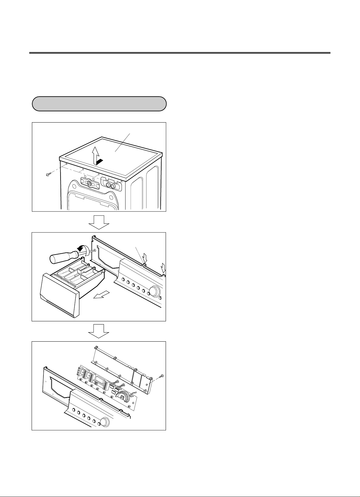
9. DISASSEMBLY INSTRUCTIONS
CONTROL PANEL
PLATE ASSY (TOP)
Hook
ƒR
Disassemble and repair the parts after pulling out power cord from the outlet.
¥LUnscrew the 2 screws on the top plate.
¥M The PLATE ASSEMBLY (Top) is pulled back
and then upward to arrow direction.
¥NThe cover (Inner) is disassembled.
¥L The PWB ASSEMBLY (Display) connectors
are disconnected.
¥M Pull out drawer, three screws are unscrewed.
¥N Press two upper hooks and pull the control
panel forward.
¥LThe PWB assembly (Display) is disconnected.
¥M When 1 screws are unscrewed on the PWB
insulator and the PWB assembly (Display) is
disassembled from the PWB insulator.
29
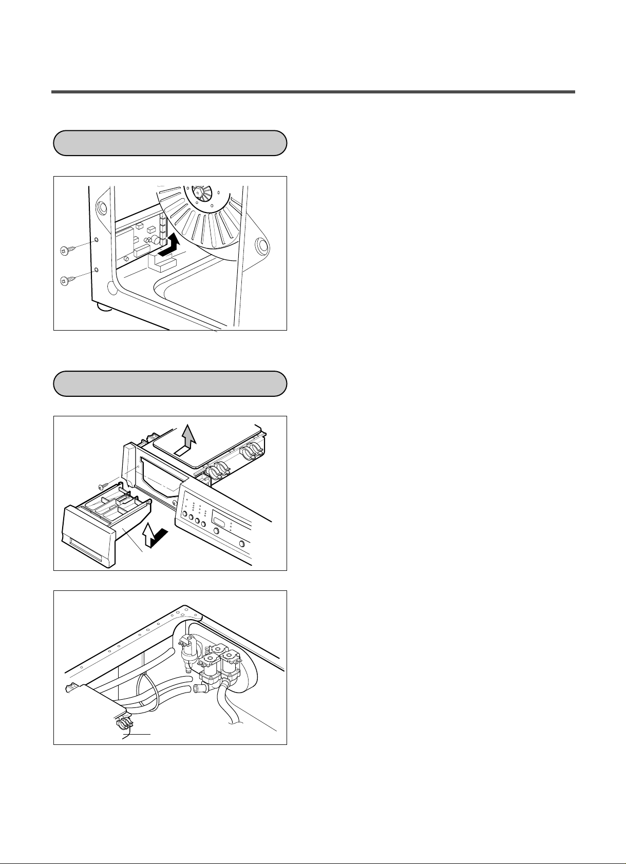
¥LThe back cover is removed.
PWB ASSEMBLY (POWER)
DISPENSER ASSEMBLY
DRAWER
DISPENSER ASSEMBLY
¥MTwo screws are unscrewed.
¥NDisconnect connector from the wiring.
¥OPull the PWB ASSEMBLY (Main) to arrow
direction.
¥LThe PLATE ASSEMBLY (Top) and the cover
(lnner) are disassembled.
¥MPull the drawer to arrow direction.
¥NTwo screws are unscrewed.
¥LThe hose clamps (6EA) and the hose are
disassembled.
¥MThe ventilation bellows are disassembled on
the tub.
30
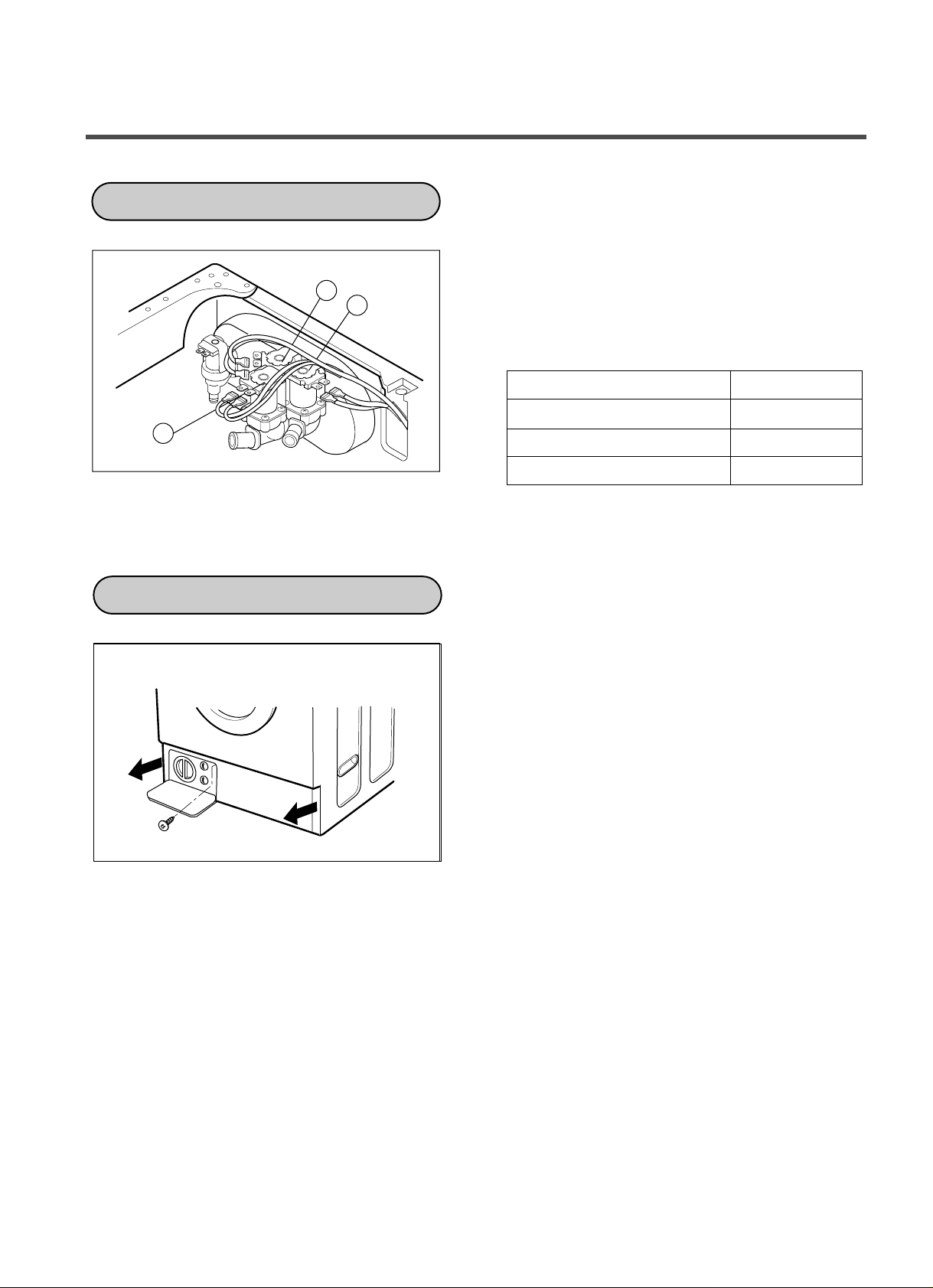
¥LDisconnect the wiring connector.
2
1
3
INLET VALVE
COVER LOWER
¥MRemove the valve by two screws of the valve
holder.
ƒTWhen reconnecting the connector
VALVE ¥L(DRY) YL/BK - BK
VALVE ¥M(LIQUID BLEACH) GY/WH - BK
VALVE ¥N(NORMAL-WASH)
VALVE (HOT) BL/RD - BK
¥L Remove the lower cover to arrow direction
after one screw is unscrewed.
WH/BK - BK
31

Cap(Remaining Hose)
DOOR
¥LOpen the door completely.
¥MRemove the two screws from the hinge.
Removing method of remained water
¥LRotate the Cap(Remaining Hose) to arrow
direction.
¥MPull it out from hose.
¡ First, prepare a bucket to put in the remained
water.
32

Cap
(Remaining Hose)
GASKET ASSEMBLY
¥LThe cabinet gasket clamp is released.
¥M Two screws are unscrewed from the cabinet
cover.
¥LOne screw is unscrewed from the lower cover.
¥M The lower cover is disassembled by pulling
out.
¥NThree screws are unscrewed from the cabinet.
¥LThe control panel is removed.
¥MScrew is unscrewed from the cabinet cover.
33

Dry
Gasket
Clamp
Tub Gasket
Clamp
Drain Hole
¥L Remove tub gasket clamp by loosening the
screw.
¥L Remove dry gasket clamp by loosening the
screw.
¥L When reassembling the gasket, put the drain
hole of the gasket downward, then assemble.
34

PULLEY, MOTOR, DAMPER
Rotor
Bolt
Friction
Damper
Bolt
Hinge
(Damper)
¥LRemove the back cover.
¥M After loosening the bolt, Rotor, pull out the
rotor.
(PULLEY)
¥LRemove the 6 bolt from the stator.
¥MDisconnect the 2 connectors.
HOW TO ASSEMBLE THE MOTOR
(MOTOR)
(FRICTION DAMPER)
¥LRemove the bolts at the Tub.
¥M The Hinge (Damper) at the base is pulled off
pressing on the snaps at the sharp end.
¥N The hinge at the base is pulled off.
(To arrow direction)
35

PUMP
HEATER
THERMISTOR
Cap
(Remaining Hose)
Screw
Pump Outlet Hose
Tub Pump Bellows
Washing
Heater
Ring Terminal
Nut
Thermistor
Bracket
Thermistor bulb
¥LRemove pump outlet hose.
¥MRemove tub pump bellows.
¥NRemove cap (Remaining Hose).
¥ODisconnect the wiring.
¥PThree screws are unscrewed from the cabinet.
¥QRemove the pump to arrow direction.
¥LLoosen the nut.
¥MRemove washing heater by pulling out.
CAUTION
When assembling the washing heater, insert
the heater to heater clip on the bottom of tub.
¥LPull it out by holding the thermistor bracket.
ƒTIf holding the wire and pulling out it, it may be
broken.
36
¥LTwo screws are unscrewed on the door and
DOOR HINGE ASSEMBLY
SWITCH ASSEMBLY, DOOR LOCK
WHEN FOREIGN OBJECT STUCK BETWEEN DRUM AND TUB
Hole
Washing Heater
the door is disassembled.
¥MThe cabinet cover clamp is removed and the
gasket is released.
¥NTwo screws are unscrewed on the door hinge.
¥OThe door hinge is disassembled by pushing
the door hinge arm inside the cabinet cover.
¥LThe cabinet cover clamp is removed and
the gasket is released.
¥MTwo screws are unscrewed.
¥NThe door lock S/W is disconnected form the
wiring connector and the strap.
¥LRemove washing heater.
¥MRemove the foreign object(wire,coin,etc) by
inserting long bar in the hole.
37

DRY DUCT
CONDENSING DUCT
Dry fan
Assembly
Dry Duct Upper
Dry Heater
Thermostat
Condensing Duct
Condensing
Bellows
Clamp
¥LRemove 5 screws and dry fan assembly.
¥MRemove 6 screws and dry duct upper.
¥LRemove 1 screw and dry heater.
¥MRemove thermostat.
¥LRemove 2 screws from cabinet.
¥LRemove clamp and condensing duct.
38
 Loading...