

Page 1
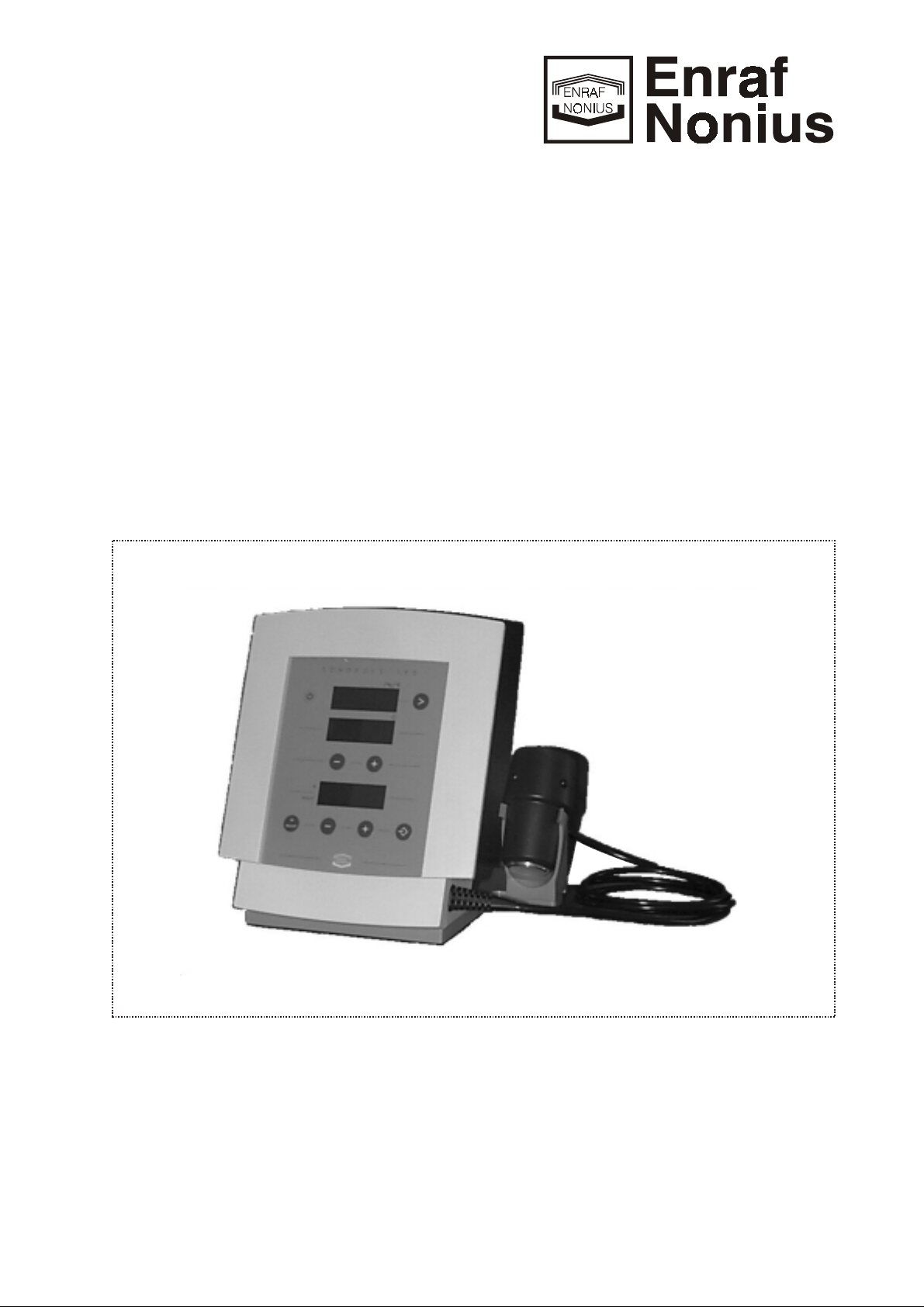
Sonopuls 190
SERVICE MANUAL
Part number: 1416770
Page 2

Page 3

Enraf-Nonius B.V. Sonopuls 190 Service Manual 1416770
Sonopuls 190
SERVICE MANUAL
Copyright:
Enraf-Nonius B.V.
P.O.Box 810
2600 AV Delft
The Netherlands
part number: 1416.770-41
PDF master 23022001
Index July 1999
1
Page 4

Enraf-Nonius B.V. Sonopuls 190 Service Manual 1416770
CONTENTS
1 INTRODUCTION
1.1 INTRODUCTORY REMARKS ............................... July 1999 1-1
1.2 GENERAL .............................................. July 1999 1-3
1.3 TECHNICAL DATA ....................................... July 1999 1-4
2 DESCRIPTION
3 TEST EQUIPMENT AND TOOLS
3.1 TEST EQUIPMENT ...................................... July 1999 3-1
3.2 TOOLS AND MATERIALS ................................. July 1999 3-1
4 MAINTENANCE
......................................... July 1999 1-1
.......................................... July 1999 2-1
............................ July 1999 3-1
......................................... July 1999 4-1
Date of issue page
4.1 GENERAL .............................................. July 1999 4-1
4.2 CHECKLIST ............................................ July 1999 4-1
4.3 FUNCTIONAL TEST ...................................... July 1999 4-1
4.4 TROUBLE SHOOTING .................................... July 1999 4-3
4.5 REPLACEMENT PROCEDURES ............................ July 1999 4-4
4.6 ADJUSTMENT PROCEDURES ............................. July 1999 4-5
5 STORAGE AND TRANSPORT
5.1 STORAGE .............................................. July 1999 5-1
5.2 TRANSPORT ........................................... July 1999 5-1
6 SPARE PARTS
6.1 ORDERING ............................................. July 1999 6-1
6.2 WARRANTEE CLAIMS .................................... July 1999 6-1
.......................................... July 1999 6-1
............................. July 1999 5-1
6.3 REPAIR SERVICE ....................................... July 1999 6-2
6.4 RETURN SHIPMENTS .................................... July 1999 6-2
Index July 1999
2
Page 5

Enraf-Nonius B.V. Sonopuls 190 Service Manual 1416770
CONTENTS
APPENDIX A SPARE PARTS LIST
APPENDIX B DRAWINGS
APPENDIX C SERVICE INFO'S
C.1 GENERAL ............................................... July 1999 C-1
C.2 REVISION HISTORY ...................................... July 1999 C-2
(contd.)
.................................. July 1999 A-1
......................................... July 1999 B-1
Fig. 1 Block diagram .................................... July 1999 B-1
Fig. 2 Sonopuls 190 front view ............................ July 1999 B-2
Fig. 3 Sonopuls 190 side view ............................. July 1999 B-3
Fig. 4 Sonopuls 190 front inside incl. PC Board ............... July 1999 B-4
Fig. 5 Sonopuls 190 Main PC Board ........................ July 1999 B-5
Fig. 6 Ultrasound Treatment Head wiring details. .............. July 1999 B-7
(Product Change Notes) ................. July 1999 C-1
Index July 1999
3
Page 6

Enraf-Nonius B.V. Sonopuls 190 Service Manual 1416770
Index July 1999
4
Page 7

Enraf-Nonius B.V. Sonopuls 190 Service Manual 1416770
1 INTRODUCTION
1.1 INTRODUCTORY REMARKS
This manual has been written for the technicians involved in the service of the Sonopuls 190.
Service can be carried out by the service organization of the supplier or by any other
technician authorized by Enraf-Nonius B.V.
The manufacturer will not be held responsible for the results of maintenance or repairs by
unauthorized persons.
Enraf-Nonius B.V. is further referred to as Enraf-Nonius
1.1.1
1.1.2
Safety Aspects
Safe execution of the procedures in this manual requires technical experience and general
knowledge of safety precautions.
Warnings, Cautions and Notes have been used throughout the manual to bring special
matters to the immediate attention of the reader.
- The
- The
- The
The sequence of steps in a procedure may also be important from the point of view of
personal safety and prevention of damage, therefore never change the sequence of procedural steps or alter a procedure.
Legal Aspects
This manual and the information herein are copyright property of Enraf-Nonius B.V. (Delft,
The Netherlands).
Enraf-Nonius B.V. disclaims any responsibility for personal injury and/or damage to
equipment caused by:
Warning
Caution
Note
which does not deserve a Warning or Caution.
concerns danger to the safety of the technician or user;
draws attention to an action which may damage the equipment;
points out a statement deserving more emphasis than the general text, but
- Negligence or disregard of a Warning or Caution;
- Deviation from any of the prescribed procedures;
- Execution or activities which are not prescribed;
- Ignorance of the general safety precautions for handling tools and the use of electricity;
- Repairs and/or adjustments made to the equipment with a patient connected.
1.1.3
Introduction July 1999
Environmental Aspects
The following materials have been used for construction of the Sonopuls 190:
- material: Polyester Control panel.
- material: ABS Housing of the unit, UTH. housing and UTH. holder.
- material: MDF Supporting plate.
Please dispose off properly in case of replacement according to the local regulations.
1-1
Page 8

Enraf-Nonius B.V. Sonopuls 190 Service Manual 1416770
1.1.4
1.1.4.1
1.1.4.2
Data registration
Equipment and customer registration/Service file
From the point of view of safety and product liability the following data must be registered for
each unit:
- Equipment data: Type (part) and serial number
- Customer data: Date of delivery of the equipment to the customer, name and full
address of the customer
- Configuration file: The actual configuration data of the equipment.
- Service file: Data of all service activities
The distributor as well as their dealer and/or service organization if any, is responsible for
these records. They must be able to provide these data when requested.
Configuration file
A configuration file gives the serial numbers and/or batch numbers of main sub-assemblies
and/or important parts per unit. The parts listed in a configuration file are defined as
registered parts. Such are for example parts as transformers, PC Boards, key-boards and
software. The registered parts of the Sonopuls 190 are marked with a "Y" for "Yes" in the
spare parts list in appendix A (column C).
1.1.5
1.1.6
Enraf-Nonius has the original configuration file of each unit. Any possible changes in the
original configuration of the supplied units must be filed and the distributor must be able to
provide this data. These changes can simply be stored in the service file of the specific unit.
Part, serial or batch number(s) of the new parts have to be mentioned.
In case of a claim we expect the distributor to report the claim and the actual configuration
data of the equipment in question.
Product documentation
The documentation set for the Sonopuls 190 also incudes an Instruction manual and a
therapy book. The instruction manual is a recommended item for all service engineers.
Ordering data:
- 1416.750 Instruction manual
- 1416.770 Service manual
- 1482.762 Therapy book "Ultrasound Therapy"
Installation
(For installation of the Sonopuls 190 see the Operating Instruction manual.)
- It is not allowed to use this unit in so-called "wet rooms" (hydrotherapy rooms).
- The mains supply connections must comply with the national requirements regarding
medical used rooms.
- Before connection of this apparatus to the mains supply, check that the mains voltage
and frequency stated on the type plate of the power supply adapter corresponds to that of
Introduction July 1999
1-2
Page 9

Enraf-Nonius B.V. Sonopuls 190 Service Manual 1416770
the mains supply. The mains supply adapter which is used for the Sonopuls 190 unit
(ENB-1530) can be used for mains voltages between 100 to 240 VAC 50 - 60 Hz.
1.1.7
1.1.8
1.1.9
Modifications
This publication could include technical inaccuracies or typographical errors. Changes are
periodically made to the information herein; these changes will be published as Service Info's
in appendix C of this Service Manual.
Product evaluation
In order to continuously improve the quality of our products, Enraf-Nonius requests her
service organizations to report any structural problem which may be discovered. When the
same problem regularly occurs or when safety problems occur, we would like you to send us
a product complaint report. The report must contain the name, the type of the product, a
detailed description of the problem, the number of the same problems, quantity of sold
equipment and your solution to the problem (if any). The product complaint report can be
found as an enclosure in the Service Reference book.
Additional Information
Please do not hesitate to contact your National sales organisation or distributor.
For additional information:
Enraf-Nonius B.V.
P.O. Box 810
2600 AV Delft
The Netherlands
1.2
Tel: +31 (0)15 - 2698400
Telefax: +31 (0)15 - 2624317
Telex: 38083 nl
GENERAL
The Sonopuls 190 is a single channel Ultra Sound (US.) unit which operates with a
frequency of 1Mhz. The compact design, the simple operation and the bright LED displays
makes the Sonopuls 190 very useful as a stand-alone US. unit.
The Ultra sound Treatment Head (UTH) has a fixed connection to the unit and can not be
connected to other units without unit calibration.
The Sonopuls 190 has been designed and manufactured to ensure the highest level of
safety; the unit itself fully complies with the IEC 601-1 and IEC 601-1-2 standards.
The power supply complies with the IEC 950 standards.
Introduction July 1999
1-3
Page 10

Enraf-Nonius B.V. Sonopuls 190 Service Manual 1416770
1.3
1.3.1
TECHNICAL DATA
General
Power supply unit:
Mains supply adapter : ENB-1530
Mains supply voltage : 100 - 240VAC.
Mains frequency : 50-60 Hz
Supply adapter output voltage : 15 VDC.
Supply adapter output current : min. 2 A.
Sonopuls 190 unit:
Current consumption : max. 1.8 A
Patient leakage current : typical 1
Ditto, single fault condition : typical 1
Safety class : II
1)
A (IEC requirement 100 A)
A (IEC requirement 500 A)
type, BF
2)
Safety approval : CE-MDD (TÜV Rheinland)
Radio interference compliance : EN60601-1-2 : 1993
Dimensions : 22 x 19.5 x 20 cm
Weight : 1.7 kg
Colour specification : EN. Custom colours
3)
1.3.2
1.3.3
1)
II: The equipment has a double insulation.
2)
BF: The equipment has a floating patient circuit. The Sonopuls 190 meets the
requirements of IEC 601 safety standards.
3)
Copies of certificates or certificates of conformity (COC) are available on request.
European union:
Marking : CE
4)
This equipment complies with all requirements of the EMC for the Medical Device
4)
Directive (93/42/EEG).
Ultrasound therapy
Ultrasound frequencies : 1 MHz ± 0,2 %
Output mode : continuous
Pulse frequency/ duty cycle : 100 Hz / 100%
Intensity : 0 - 2 W/cm
2
continuous
Output mode : pulsed
Pulse frequency/ duty cycle : 100 Hz / 5, 10, 20, 50, 100%
Intensity : 0 - 3 W/cm
: 0 - 2 W/cm
2
, duty cycle 5, 10, 20, 50%
2
, duty cycle 80%
Contact control threshold level : 65 % of initial value
(min. output power 0.3W/cm² = 1.5 W)
Display modes : intensity in W/cm
2
and output power in W (SATP 4))
Indication accuracy : ± 20 % (for any level above 10 % of maximum)
Introduction July 1999
1-4
Page 11

Enraf-Nonius B.V. Sonopuls 190 Service Manual 1416770
Timer : 0 - 30 minutes, coupled to contact control, 0 - 10
minutes in 0.5 minute steps, 10 - 30 minutes in 1
minute steps
4)
SATP: Spatial Average Temporal Peak (mean pulse power)
1.3.4
Ultrasound Treatment Heads
Treatment head, large, 1 MHz:
Geometrical surface : 6.2 cm²
ERA
BNR
5)
6)
: 5.0 cm²
: Max. 6.0
Type : Collimating
Side wall radiation : Max.10 mW/cm²
5)
The Effective Radiating Area (ERA) is defined as the geometrical area of a plane (in
square centimetres), parallel to, and at a distance of 5 mm from the front of the treatment
head, where the ultrasound intensity is more than 5 % of the maximum intensity in that
plane.
6)
The Beam Non-uniformity Ratio (BNR) is defined as the ratio of the maximum peak
intensity somewhere in the ultrasound beam and the effective intensity of that ultrasound
beam.
ERA and BNR are measured according to the FDA definitions
Introduction July 1999
1-5
Page 12

Enraf-Nonius B.V. Sonopuls 190 Service Manual 1416770
Introduction July 1999
1-6
Page 13

Enraf-Nonius B.V. Sonopuls 190 Service Manual 1416770
2 DESCRIPTION
Because of the modular construction of the Sonopuls 190 the description is on block diagram
level.
2.1
2.1.1
BLOCK DIAGRAM
The electronic circuit of the Sonopuls 190 is located on 2 modules:
- Application / display module (also referred to as main PC Board).
- User interface module (also referred to as keyboard)
The Ultrasound Treatment Head (UTH) is connected to the unit without using an connector
which makes it unable to disconnect the UTH by the user. The electronic circuit of the
treatment head (feedback circuit) is found on the main PC Board. The treatment heads used
with other series are equipped with a feedback and an head id. circuit inside the UTH which
makes the heads interchangeable with other units. Other units are able to provide two output
frequencies 1 and 3 Mhz, the Sonopuls 190 unit is a single frequency unit. Because the UTH
which is used with the Sonopuls 190 unit does not have this circuits inside, the UTH must be
calibrated to the unit in question. One advantage is that the treatment cable is available as a
spare part because it is a part of the electronic circuit. The calibration routine covers the
complete unit including cable and treatment head assembly.
Application module
The function of the application module is to supply the Ultra Sound (US.) drive current for the
Ultrasound Treatment Head (UTH) connected to the Sonopuls 190 unit.
The Ultra Sound drive current is an alternating current at a frequency of 1MHz and can be
either continuous or pulsed mode.
(see appendix B fig. 1)
(main PC Board)
2.1.2
The application module comprises the following circuits:
- US. micro controller circuit
- US. measuring circuits
- US. driver and output stages
- Timer circuits
- LED display
The ultrasound treatment head connected to the Sonopuls 190 unit is specially designed and
it has a permanent connection to the unit. The UTH. does not have a connector and
therefore it is not possible to disconnect it from the unit.
User interface module
The keyboard is found at the front of the Sonopuls 190 unit. The switch-matrix is decoded at
the main PC Board. The LED displays ( which are a part of the main PC Board) will give a
clear view of the treatment parameters and treatment timer.
(keyboard)
Description July 1999
2-1
Page 14

Enraf-Nonius B.V. Sonopuls 190 Service Manual 1416770
2.1.3
Ultrasound Treatment Head
The Ultrasound Treatment Head (UTH) comprises the following part:
- Ultrasound crystal
The treatment head itself is not a serviceable item because the head parameters (impedance
of the crystal) are to be factory determined. The head parameters (crystal properties)
required for calibration of the unit are found on a label at the main PC Board connector side
of the treatment head cable.
(UTH)
Description July 1999
2-2
Page 15

Enraf-Nonius B.V. Sonopuls 190 Service Manual 1416770
3 TEST EQUIPMENT AND TOOLS
3.1
3.2
TEST EQUIPMENT
For the repair and maintenance procedures of the Sonopuls 190 the following test equipment
and accessories are required:
- Digital multimeter 3 1/2 digit, accuracy better than 1 %. For example Fluke 77
- Safety tester according IEC 601-1. For example a Rigel Safety tester, model 233
- Ultrasound dummy load with adaptor ring, see note below (see spare parts list, item no:
003)
Note:
Note:
Note:
TOOLS AND MATERIALS
It is assumed that a complete set of precision engineering tools is available. For the service
of the Sonopuls 190 the following additional tools are required:
The ultrasound dummy load, part number 1417802, is only used as an optimum
acoustical load for ultrasound frequencies and can not be used as an output meter.
The ultrasound dummy load must be filled with degassed water. Boil the water for
approx. 15 minutes. Wait for the water to cool down to room temperature (± 20 °C)
before use.
Always use calibrated equipment.
- Anti-static bench mat with earthing wire and wrist strap
- Tool for removal of Dual In Line (DIL) integrated circuits, 0.3"
- Special tool for removing the top cover of the Ultrasound Treatment Head (see spare
parts list, item no: 004)
Test equipment and tools July 1999
3-1
Page 16

Enraf-Nonius B.V. Sonopuls 190 Service Manual 1416770
Test equipment and tools July 1999
3-2
Page 17

Enraf-Nonius B.V. Sonopuls 190 Service Manual 1416770
4 MAINTENANCE
4.1
4.2
4.2.1 Modifications, if any, according to the "Service Info" sheets. See appendix C of this manual
4.2.2 Visual inspection. Check the electrical wiring for safety and check that all components are
4.2.3 Check that all accessories are in good condition.
4.2.4 Functional test (see chapter 4.3).
4.2.5 File all service activities.
4.3
GENERAL
We recommend to check the Sonopuls 190 annually.
CHECKLIST
The following procedures must be carried out during an inspection and/or after every repair:
for further information.
properly fastened.
FUNCTIONAL TEST
4.3.1
4.3.2
4.3.3
Self test
Connect the Sonopuls 190 to the mains and switch on the equipment.
The Sonopuls 190 will carry out the so-called self test for approx. 2 seconds.
At the end the buzzer sounds (otherwise see par. 4.4.1.2). It is assumed that when the
selftest is passed all functions of the Sonopuls 190 are okay.
Switch off the Sonopuls 190.
Display test
Switch on the unit and check during the selftest that no segments fail in the LED displays
(otherwise see par. 4.4.1.3).
Switch off the Sonopuls 190.
Software versions
Press and keep depressed the intensity/power (W-W/cm²) button and switch ON the unit.
The software version is displayed on the displays from the top to the bottom display
For example:
Top display: 041
Centre display: 67
Bottom display: 01
Maintenance July 1999
4-1
Page 18

Enraf-Nonius B.V. Sonopuls 190 Service Manual 1416770
The software version is: 0416. 701
4.3.4
4.3.5
Keyboard test
Switch on the unit and check that all switches are working properly (otherwise see par.
4.4.1.4).
Switch off the Sonopuls 190.
Program memory test
Switch on the unit and write down the user default switch-ON treatment parameters.
Set the following treatment parameters:
Therapy mode: 100% (duty cycle)
Treatment time: 10 min.
Intensity: 1 W/cm²
Store the parameters above at the default switch-ON memory location as follows:
- Switch OFF the unit by pressing the ON/OFF key.
- Press the memory retrieve key and the ON/OFF key simultaneously (the therapy mode
display shows “o”).
- Release both keys.
4.3.6
Check that the values on the display are identical to the values which are entered above
(otherwise see par. 4.4.1.5).
Restore the user set values which are written down at the start of the program test.
Switch off the Sonopuls 190.
Acoustical output power test US.
Switch on the unit, wait for the buzzer and set the following treatment parameters:
Therapy mode: 100% (duty cycle)
Treatment time: 10 min.
Intensity: 1 W/cm²
Check that the intensity display is blinking (no contact).
When the buzzer is switched to ON also a beeping sound is heard *.
Put the UTH in the ultrasound dummy load. Ensure that there are no air-bubbles locked
under the treatment surface of the UTH. The intensity display will stop flashing, the buzzer
stops beeping and the timer will start running when the treatment surface of the UTH is fully
under water (otherwise see par. 4.4.1.6).
Note:
The ultrasound dummy load must be filled with degassed water to prevent
reflections of the ultrasound beam and to prevent false display readings.
Put the Ultrasound Treatment Head into the Ultrasound dummy load.
Check that the display stops blinking and that the treatment time is counting down.
Maintenance July 1999
4-2
Page 19

Enraf-Nonius B.V. Sonopuls 190 Service Manual 1416770
* Switching the beeper ON/OFF is done as follows:
- Switch OFF the unit
- Press the therapy mode (duty cycle) and the ON switch simultaneously
(the therapy mode display shows “o”)
- Release the ON switch
Switching OFF the beeper is done the same (toggle switch).
Note:
4.3.7
4.4
4.4.1
4.4.1.1 Sonopuls 190 does not 1. Check mains power supply.
4.4.1.2 Selftest fails 1. Check/replace main PC Board.
4.4.1.3 Display test fails 1. Check/replace connection between
Safety tests
Check the earth leakage current in normal condition (N.C.) as well as in the single fault
condition (S.F.C.) (see technical data).
TROUBLE SHOOTING
Trouble shooting list
Failure indication: Action to be taken:
switch on; displays fail 2. Check mains power supply adapter.
to light 3. Check/replace power supply connection.
The contact control does not work when the intensity is set to 0.1 or 0.2 W/cm².
4. Check/replace main PC Board.
5. Check/replace wiring.
main PC Board and LED displays.
2. Check/replace main PC Board.
4.4.1.4 Keyboard test fails 1. Check/replace connection between
main PC Board front panel.
2. Check/replace main PC Board.
4.4.1.5 Program memory test fails 1. Check/replace main PC Board.
4.4.1.6 Acoustical output power test US. fails 1. Check/replace treatment head cable.
2. Check/replace treatment head.
3. Check/replace main PC Board.
4.4.1.7 Safety test fails 1. Check/replace wiring
2. Check/replace transformer
3. Replace main PC Board
4.4.2
Maintenance July 1999
Error codes
The Sonopuls 190 is continuously checked for correct operation by the software. If malfunctioning is detected an error message is displayed. An error message is indicated by an
4-3
Page 20

Enraf-Nonius B.V. Sonopuls 190 Service Manual 1416770
audio signal and a blinking error code on the displays of the Sonopuls 190.
Most errors will disappear when the unit is switched OFF and is disconnected from the mains
supply. Reconnecting to the mains supply after approx. 15 sec. and switching ON, the unit
should work properly. For errors which occur after the procedure described above see the
Error code list.
The list below indicates the error codes which are field-serviceable. If an errorcode is
displayed
for repair.
other than in this list
, the PC Board must be replaced and sent to Enraf-Nonius
4.4.3
4.5
Error code list
Error code / description: Action to be taken:
001 Checksum error flash error - Replace the micro controller (IC1) see
appendix B fig. 5.
002 Eeprom time-out error - Replace main PC Board (see par. 4.5.4).
003 Eeprom time-out error - Replace main PC Board (see par. 4.5.4).
004 Stack invalid value - Replace the micro controller (IC1) see
appendix B fig. 5.
005 Watchdog error - Replace main PC Board (see par. 4.5.4).
006 Watchdog timeout - Replace main PC Board (see par. 4.5.4).
007 Micro controller error - Replace the micro controller (IC1) see
appendix B fig. 5.
REPLACEMENT PROCEDURES
4.5.1
4.5.2
Maintenance July 1999
General
When handling static sensitive devices such as the PC Boards of the Sonopuls 190 the
following precautions should be observed:
- Persons should be earthed by means of a wrist strap
- Ground all electrical equipment, work-bench, soldering iron etc.
After every repair a functional test must be performed (see par. 4.3).
Power supply adaptor
The power supply adapter (ENB-1530) of the Sonopuls 190 unit is a not serviceable item.
Do not open or modify the power supply adaptor.
4-4
Page 21

Enraf-Nonius B.V. Sonopuls 190 Service Manual 1416770
4.5.3
4.5.4
4.5.5
Cover
Removal: Switch off the unit and remove the supply cable from the unit. Remove the
four screws at the rear side of the front cover.
Installation: Installation of the front cover is in reverse order of the removal procedure.
Main PC Board
(incl. LED displays)
Removal: See par. 4.5.3 for removal of the cover. Remove the UTH. connector (CN1),
supply connector (CN2) and the keyboard connector (CN4) from the main
PC Board. The removal of the PC Board needs no further explanation.
Installation: Installation of the PC Board is in reverse order of the removal procedure.
After replacement of the main PC Board the unit requires calibration (see
par. 4.6.1).
Ultrasound Treatment Head
(UTH. complete with cable)
Removal: See par. 4.5.3 for removal of the cover. Remove the UTH. connector (CN1).
Remove the Ultra Sound Treatment head connection cable from the housing.
4.5.6
Installation: Installation of the UTH. is in reverse order of the removal procedure.
After replacement of an UTH. the unit requires calibration (see par. 4.6.1).
Note:
The treatment head itself is not a serviceable item, this is because the head
parameters are to be factory determined for correct calibration. Replacing
separate parts of the head will result in changing of the UTH parameters.
Ultrasound Treatment Head cable
Removal: See par. 4.5.3 for removal of the cover. See par. 4.5.5 for removal of the
UTH. Remove the cover at the top side of the UTH with the special tool (see
par. 3.2). Remove the inner locking ring inside the UTH. Disconnect the
connector and the two ground connections. Remove the cable from the
UTH. housing.
Installation: Installation of the UTH. cable is in reverse order of the removal procedure.
See appendix B fig. 6 for wiring details.
After replacement of a UTH. cable the unit requires calibration
(see par. 4.6.1)
Note:
When replacing the cable attatch the UTH. parameter label from the old
cable at the main PC Board connector side of the new treatment head cable.
Caution: Never
change the length of the cable of the treatment head. Changing the
length will also change the impedance of the head/cable assembly. The
output power of the unit will also change. Without special equipment it is not
possible to determine the UTH. constant (C
) which is required for
UTH.
calibration of the unit (see par. 4.6.1).
Maintenance July 1999
4-5
Page 22

Enraf-Nonius B.V. Sonopuls 190 Service Manual 1416770
4.6
4.6.1
ADJUSTMENT PROCEDURES
When changes are made to the combination of the main PC Board and Treatment head the
unit must be calibrated.
The main PC board is tested and calibration values are determined at the factory.
.
C
The calibration value (
) is found on an adhesive label on the main PC Board, see
PCB
appendix B fig. 4 item A.
The head constant(
C
), also factory determined, is also required for calibration of the unit
UTH
and is found on a label on the treatment head cable at the main PC Board connector side.
Calibration routines of the complete unit is found below at chapter 4.6.1.
The adjustment procedure for the Sonopuls 190 is carried out under the following test
conditions:
- The mains voltage must correspond with the technical specifications of the Sonopuls 190.
- The ambient temperature must be 25°C ± 5°C.
Ultrasound Unit/Treatment Head combination adjustment
After replacing the main PC Board and/or an ultrasound treatment head the Sonopuls 190
unit must be calibrated.
For calibration of the UTH. two values are required:
4.6.1.1
C
PCB.
Main PC Board constant is factory determined, found on an adhesive label on the
Main PC Board (see Appendix B fig. 4, item A).
C
UTH.
Treatment head constant (crystal properties) is factory determined and is found on
a label at the main PC Board connector side of the treatment head cable.
The calibration is as follows:
Output power calibration:
- Connect an Ultrasound Treatment Head to connector CN1.
- Put the UTH. into the ultrasound dummy load (see par. 3.1).
- Set the unit to an output power of 1W/cm² (5W) continuous output power.
- Set the treatment timer to approx 5 min.
U
- Measure the control voltage U
TP1
of the output stage (mV in DC-range) at
TP1
TP1 (positive connection) and ground, see Appendix B, fig. 4.
C
UTH.
- Find the value of C
found on a label at the main PC Board connector side
UTH.
of the UTH. cable.
Calculate - The value U
= C
U
TP1
PCB.
as follows:
TP1
X C
UTH.
P2 - Adjust the voltage U
(with a tolerance ± 1mV) measured at TP1 with
TP1
potentiometer P2 (see Appendix B, fig. 4)
Maintenance July 1999
4-6
Page 23

Enraf-Nonius B.V. Sonopuls 190 Service Manual 1416770
Example output power calibration:
4.6.1.2
=
112
100.8
mV (±1mV)
0.90
found on the main PC Board is
C
PCB.
C
found on the Ultrasound Treatment Head is
UTH.
PCB.
X C
TP1
should be adjusted with potentiometer P2 to:
112 X 0.90
=
UTH.
The voltage at
U
= C
TP1
Contact control calibration:
- Set the unit to an output power of 1W/cm² (5W) continuous output power.
U
CC
- Measure the contact control threshold voltage UCC at TP2 (positive
connection) and ground (V in DC-range), see Appendix B, fig. 4.
P1 - Turn potentiometer P1 until the output power display blinks (contact control
switched on, output power approx. 0.3 Watt).
Measure - Turn potentiometer P1 until the output power display just stops blinking.
(unit switches between contact control ON/OFF).
U
CC
Calculate - The value U
- Make a note of the value found above (to be used for calculation of U
as follows:
TP2
= 1.25 X U
U
TP2
(value measured above)
CC
TP2
).
P1 - Adjust the voltage U
(with a tolerance ± 0.05V) measured at TP2 with
TP2
potentiometer P1 (see Appendix B, fig. 4) to the value equal to the voltage
found according to the calculation above.
Example contact control calibration:
Measured value of U
. at TP2 on the main PC Board is
CC
2.30V
The voltage at
= 1.25 X UCC =
U
TP2
TP2
should be adjusted with potentiometer P1 to:
1.25 X 2.30
=
2.88
V (±0.05V)
The unit/treatment head assembly is now calibrated.
- Switch off the unit
Perform a functional test, see par. 4.3., after repairing or calibrating the Sonopuls 190 unit.
Maintenance July 1999
4-7
Page 24

Enraf-Nonius B.V. Sonopuls 190 Service Manual 1416770
Maintenance July 1999
4-8
Page 25

Enraf-Nonius B.V. Sonopuls 190 Service Manual 1416770
5 STORAGE AND TRANSPORT
This chapter contains information about the storage and transport of the Sonopuls 190 and
the storage conditions for the spare parts.
5.1
5.2
STORAGE
The Sonopuls 190 and any accessories must always be stored in their original packing.
The long term storage conditions are:
- The unit must be stored at room temperature (± 20 °C).
- The relative humidity should be less than 50%.
- The storage room must be clean, dust-free and ventilated.
For the spare parts of the Sonopuls 190 the above mentioned requirements also apply.
TRANSPORT
The Sonopuls 190 and any accessories should always be transported in its original packing.
This packing withstands normal shocks and vibration caused by transport.
During transport and short term storage the temperature should be between - 40 °C and + 70
°C. The absolute temperature is not too important, however, rapid fluctuations in temperature
must be avoided.
Storage and transport July 1999
5-1
Page 26

Enraf-Nonius B.V. Sonopuls 190 Service Manual 1416770
Storage and transport July 1999
5-2
Page 27

Enraf-Nonius B.V. Sonopuls 190 Service Manual 1416770
6 SPARE PARTS
This chapter deals with placing orders for spare parts (refer to appendix A) as well as the
listing of the actual spare parts (appendix A, spare parts list).
6.1
6.1.1
ORDERING
Spare parts can only be ordered if the following data is supplied:
- Part number
- Description
- Quantity
- Shipping details (Incoterms); normal or rapid delivery
The required data is mentioned in appendix A. For the actual spare parts programme please
refer to in the spare parts catalogue which is published every year.
Enraf-Nonius only supplies parts mentioned in appendix A. Standard parts such as screws,
nuts, cleaning agents and the like are not supplied by Enraf-Nonius; these parts must be
purchased locally.
Send your order to your contact person at the sales department of Enraf-Nonius After
receipt of an order you will receive a confirmation. Always check the ordering data.
Normal delivery
The procedure for 'normal delivery' is the standard procedure for processing your spare parts
orders. This procedure is suitable for spare parts orders which do not require rapid delivery
such as stock replenishment orders
6.1.2
6.1.3
6.2
If you have an agreement with Enraf-Nonius about fixed delivery dates, the spare parts will
be send together with the next delivery unless otherwise agreed.
Rapid delivery (by DHL-courier)
If spare parts for an urgent customer repair are not on local stock then rapid delivery can be
requested from Enraf-Nonius The DHL-costs will be charged. Note that rapid delivery is
subject to stock availability.
Ordering PC Boards
Printed circuit boards are only obtainable as spare part in their latest version. Consult the
technical documentation for instructions of how to modify the latest version of the PC Board
for use in older versions of the apparatus.
WARRANTEE CLAIMS
Warrantee claims must be provided with the Enraf-Nonius-invoice number and with the type
and serial number of the equipment in question. Enraf-Nonius may ask you to return the
(defective) spare parts.
Spare parts July 1999
6-1
Page 28

Enraf-Nonius B.V. Sonopuls 190 Service Manual 1416770
6.3
6.4
REPAIR SERVICE
Defective PC Boards can be offered to Enraf-Nonius for repair. The repair order can be
presented to Enraf-Nonius by means of the "Authorization Request for Return Shipment".
Refer to the return shipment procedure as per par. 6.4.
RETURN SHIPMENTS
To return defective equipment and/or spare parts an authorization of Enraf-Nonius is
required. To get an authorization use the "Authorization Request for Return Shipment" of
which a copy can be found in the Service General Information guide.
The procedure is as follows:
1. Fill in the "Authorization Request for Return Shipment" form and send this form by fax to
your agent at Enraf-Nonius
2. Within two working days you will receive the form back again by fax. You will notice that
the R(eturn) number has been filled in; this means that your return shipment has been
registered by Enraf-Nonius
3. Note this R(eturn) number on the address label. Pack up the goods together with the
"Authorization Request for Return Shipment" form (or a photo copy).
After the repair order has been carried out the goods will be returned as soon as possible.
If you have an agreement with Enraf-Nonius about fixed delivery dates, the repaired goods
will be sent together with the next delivery.
Spare parts July 1999
6-2
Page 29

Enraf-Nonius B.V. Sonopuls 190 Service Manual 1416770
APPENDIX A
The spare parts list on the next page shows all available spare parts.
The various columns are explained hereafter:
Item: The item number refers to the number on the illustration(s).
R1: A number in this column indicates a suggested quantity of spare parts for
R2: A number in this column indicates the minimum recommended quantity for
C: A "Y"(yes) in this column marks the so-called "Registered" items. The
Part no.: The part number column shows the code for ordering the part from
Description 1: This column gives the general description of the spare part.
Description 2: This column gives the technical specification of the spare part.
SPARE PARTS LIST
users (Quantity of equipment in use: 1 - 3).
spare parts stock at the local service organization (Quantity of equipment in
use: 1 - 50).
service engineer must record the type and serial number of the spare part as
well as type and serial number of the unit in case of replacement.
Enraf-Nonius.
Appendix A July 1999
A-1
Page 30

Enraf-Nonius B.V. Sonopuls 190 Service Manual 1416770
Spare parts list
Item C R1 R2 Part no. Description1 Description2
001 0 2 3444669 Cable, for Ultra Sound Treatment head
002 0 2 2994815 Holder, for UTH
003 0 0 1417802 Test Equipment, US. dummy load
004 0 0 0434801 Tool, wrench key for UTH
005 0 2 3444110 Supply unit, mains, for Sonopuls 190 unit, 15Volt,
without mains cable
006 0 2 3444111 Cable assembly, mains supply (supply unit -> wall socket,
EURO)
CN 0 1 0416600 Connector, power supply
IC1 Y 0 0 0416701 IC, micro controller
PCB1 Y 0 2 0416800 PC Board, main, incl. LED displays
UTH Y 0 2 0416310 Treatment head, Ultrasound, 1 MHz, 5.0 cm², complete
Appendix A July 1999
A-2
Page 31

Enraf-Nonius B.V. Sonopuls 190 Service Manual 1416770
APPENDIX B
DRAWINGS
Figure 1 Block diagram.
Appendix B February 2001
B-1
Page 32

Enraf-Nonius B.V. Sonopuls 190 Service Manual 1416770
Figure 2 Sonopuls 190 front view.
Appendix B February 2001
B-2
Page 33

Enraf-Nonius B.V. Sonopuls 190 Service Manual 1416770
Figure 3 Sonopuls 190 side view.
Appendix B February 2001
B-3
Page 34

Enraf-Nonius B.V. Sonopuls 190 Service Manual 1416770
Figure 4 Sonopuls 190 front inside incl. PC Board.
Appendix B February 2001
B-4
Page 35

Enraf-Nonius B.V. Sonopuls 190 Service Manual 1416770
&1
3
3
&1
&1
&1
&1
3&% ,&
Figure 5 Sonopuls 190 Main PC Board.
Appendix B February 2001
B-5
Page 36

Enraf-Nonius B.V. Sonopuls 190 Service Manual 1416770
PC Board specification
Product code: 0416690 PC Board, application US.
Description
Ultrasound (US.) application module for Sonopuls 10 unit.
Layers (single/bi/multi): multi-layer
Product code(s)
0416690 Part no of complete assy (printed on label on PC Board)
2557114 Part no of PC Board only (printed on PC Board)
0416800 Equivalent service (spare part) part no (not printed on PC Board; used for ordering only)
Software
0416701 ID 1 version 01 in EPROM
Service
Circuit adjustments: Yes
Serviceable parts for FSE: Micro controller incl. program memory
Repairable by manufacturer: Yes
Application / compatibility
Can be used for Sonopuls 190 units.
Notes
Appendix B February 2001
B-6
Page 37

Enraf-Nonius B.V. Sonopuls 190 Service Manual 1416770
Top cover and locking ring are removed
Figure 6 Ultrasound Treatment Head wiring details.
Appendix B February 2001
B-7
Page 38

Enraf-Nonius B.V. Sonopuls 190 Service Manual 1416770
Appendix B February 2001
B-8
Page 39

Enraf-Nonius B.V. Sonopuls 190 Service Manual 1416770
APPENDIX C
C.1
GENERAL
The technical information in the service manuals of Enraf-Nonius is up to date from the date
of issue.
The necessary additional information (of any kind) will be provided in the following way:
- as supplements to the manual, or
- as revised editions (chapters) of the manual, or
- as Service Info's (product change notes).
Once every year Enraf-Nonius publishes a Service Info which lists all the published Service
Info's until sofar.
Once every year Enraf-Nonius publishes a Service Info which lists all the published service
manuals. Note that from that moment on these manuals contain all the published Service
Info's until sofar. The relevant technical information will then be bound in this appendix.
When a supplement or a revision is made to the manual, a "document history file" is added to
this chapter. This file will give information about the date of issue of supplements or
revisions.
SERVICE INFO'S (Product Change Notes)
Appendix C February 2001
C-1
Page 40

Enraf-Nonius B.V. Sonopuls 190 Service Manual 1416770
C.2
Revision history
First edition: July 1999
Revisions:
Chapter: Revision: Date of issue: page
Appendix B Front inside drawing, fig 4 app. B, corrected February 2001 B-4
(TP1 and TP3 changed)
Service Info SI 190 - 01, date December 1999, removed February 2001
from manual, integrated into page B-4 (see above)
Appendix C February 2001
C-2
Page 41

Page 42

Subsidiary of Henley Healthcare Inc.
Enraf-Nonius B.V.
P.O. Box 810
2600 AV Delft
The Netherlands
 Loading...