


Radarmed 650
SERVICE MANUAL
Part number: 1409773

Enraf-Nonius B.V. |
Radarmed 650 Service Manual |
1409773 |
|
|
|
Radarmed 650
SERVICE MANUAL
Copyright:
Enraf-Nonius B.V.
P.O.Box 810
2600 AV Delft
The Netherlands
part number: 1409.773-40
Index |
1 |
January 2000 |

Enraf-Nonius B.V. |
Radarmed 650 Service Manual |
1409773 |
|
|
|
CONTENTS |
Date of issue |
page |
||
1 |
INTRODUCTION . . . . . . . . . . . . . . . . . . . . . . . . . . . . . . . . . . . . . . . . . |
Jan. |
2000 |
1-1 |
1.1 |
INTRODUCTORY REMARKS . . . . . . . . . . . . . . . . . . . . . . . . . . . . . . . |
Jan. |
2000 |
1-1 |
1.2 |
GENERAL . . . . . . . . . . . . . . . . . . . . . . . . . . . . . . . . . . . . . . . . . . . . . . |
Jan. |
2000 |
1-3 |
1.3 |
TECHNICAL DATA . . . . . . . . . . . . . . . . . . . . . . . . . . . . . . . . . . . . . . . |
Jan. |
2000 |
1-4 |
2 |
DESCRIPTION . . . . . . . . . . . . . . . . . . . . . . . . . . . . . . . . . . . . . . . . . . |
Jan. |
2000 |
2-1 |
3 |
TEST EQUIPMENT AND TOOLS . . . . . . . . . . . . . . . . . . . . . . . . . . . . |
Jan. |
2000 |
3-1 |
3.1 |
TEST EQUIPMENT . . . . . . . . . . . . . . . . . . . . . . . . . . . . . . . . . . . . . . |
Jan. |
2000 |
3-1 |
3.2 |
TOOLS AND MATERIALS . . . . . . . . . . . . . . . . . . . . . . . . . . . . . . . . . |
Jan. |
2000 |
3-1 |
4 |
MAINTENANCE . . . . . . . . . . . . . . . . . . . . . . . . . . . . . . . . . . . . . . . . . |
Jan. |
2000 |
4-1 |
4.1 |
GENERAL . . . . . . . . . . . . . . . . . . . . . . . . . . . . . . . . . . . . . . . . . . . . . . |
Jan. |
2000 |
4-1 |
4.2 |
CHECKLIST . . . . . . . . . . . . . . . . . . . . . . . . . . . . . . . . . . . . . . . . . . . . |
Jan. |
2000 |
4-1 |
4.3 |
FUNCTIONAL TEST . . . . . . . . . . . . . . . . . . . . . . . . . . . . . . . . . . . . . . |
Jan. |
2000 |
4-1 |
4.4 |
TROUBLE SHOOTING . . . . . . . . . . . . . . . . . . . . . . . . . . . . . . . . . . . . |
Jan. |
2000 |
4-2 |
4.5 |
REPLACEMENT PROCEDURES . . . . . . . . . . . . . . . . . . . . . . . . . . . . |
Jan. |
2000 |
4-3 |
4.6 |
ADJUSTMENT PROCEDURES . . . . . . . . . . . . . . . . . . . . . . . . . . . . . |
Jan. |
2000 |
4-5 |
5 |
STORAGE AND TRANSPORT . . . . . . . . . . . . . . . . . . . . . . . . . . . . . |
Jan. |
2000 |
5-1 |
5.1 |
STORAGE . . . . . . . . . . . . . . . . . . . . . . . . . . . . . . . . . . . . . . . . . . . . . . |
Jan. |
2000 |
5-1 |
5.2 |
TRANSPORT . . . . . . . . . . . . . . . . . . . . . . . . . . . . . . . . . . . . . . . . . . . |
Jan. |
2000 |
5-1 |
6 |
SPARE PARTS . . . . . . . . . . . . . . . . . . . . . . . . . . . . . . . . . . . . . . . . . . |
Jan. |
2000 |
6-1 |
6.1 |
ORDERING . . . . . . . . . . . . . . . . . . . . . . . . . . . . . . . . . . . . . . . . . . . . . |
Jan. |
2000 |
6-1 |
6.2 |
WARRANTEE CLAIMS . . . . . . . . . . . . . . . . . . . . . . . . . . . . . . . . . . . . |
Jan. |
2000 |
6-1 |
6.3 |
REPAIR SERVICE . . . . . . . . . . . . . . . . . . . . . . . . . . . . . . . . . . . . . . . |
Jan. |
2000 |
6-2 |
6.4 |
RETURN SHIPMENTS . . . . . . . . . . . . . . . . . . . . . . . . . . . . . . . . . . . . |
Jan. |
2000 |
6-2 |
Index |
2 |
January 2000 |

Enraf-Nonius B.V. |
Radarmed 650 Service Manual |
1409773 |
|
|
|
CONTENTS (contd.) |
|
|
|
||
APPENDIX A SPARE PARTS LIST . . . . . . . . . . . . . . . . . . . . . . . . . . . . . . . . . |
Jan. |
2000 |
A-1 |
||
APPENDIX B DRAWINGS . . . . . . . . . . . . . . . . . . . . . . . . . . . . . . . . . . . . . . . . |
Jan. |
2000 |
B-1 |
||
|
Fig. 1 |
Block diagram . . . . . . . . . . . . . . . . . . . . . . . . . . . . . . . . . . . |
Jan. |
2000 |
B-1 |
|
Fig. 2 |
Radarmed 650 top view . . . . . . . . . . . . . . . . . . . . . . . . . . . . |
Jan. |
2000 |
B-2 |
|
Fig. 3 |
Chassis front view . . . . . . . . . . . . . . . . . . . . . . . . . . . . . . . . |
Jan. |
2000 |
B-3 |
|
Fig. 4 |
Chassis side view . . . . . . . . . . . . . . . . . . . . . . . . . . . . . . . . |
Jan. |
2000 |
B-4 |
|
Fig. 5 |
Top cover inside . . . . . . . . . . . . . . . . . . . . . . . . . . . . . . . . . . |
Jan. |
2000 |
B-5 |
|
Fig. 6 |
Main PC Board . . . . . . . . . . . . . . . . . . . . . . . . . . . . . . . . . . . |
Jan. |
2000 |
B-7 |
|
Fig. 7 |
Distributor PC Board . . . . . . . . . . . . . . . . . . . . . . . . . . . . . . |
Jan. |
2000 |
B-9 |
|
Fig. 8 |
Display PC Board . . . . . . . . . . . . . . . . . . . . . . . . . . . . . . . . . |
Jan. |
2000 |
B-11 |
|
Fig. 9 |
Display interface PC Board . . . . . . . . . . . . . . . . . . . . . . . . . |
Jan. |
2000 |
B-13 |
|
Fig. 10 |
Wiring diagram . . . . . . . . . . . . . . . . . . . . . . . . . . . . . . . . . . . |
Jan. |
2000 |
B-15 |
|
Fig. 11 |
Mains distributor strip configuration . . . . . . . . . . . . . . . . . . . |
Jan. |
2000 |
B-16 |
|
Fig. 12 |
Power supply diagram . . . . . . . . . . . . . . . . . . . . . . . . . . . . . |
Jan. |
2000 |
B-16 |
APPENDIX C SERVICE INFO'S (Product Change Notes) . . . . . . . . . . . . . . . . |
Jan. |
2000 |
C-1 |
||
C.1 |
GENERAL . . . . . . . . . . . . . . . . . . . . . . . . . . . . . . . . . . . . . . . . . . . . . . |
Jan. |
2000 |
C-1 |
|
C.2 |
REVISION HISTORY . . . . . . . . . . . . . . . . . . . . . . . . . . . . . . . . . . . . . |
Jan. |
2000 |
C-2 |
|
Index |
3 |
January 2000 |

Enraf-Nonius B.V. |
Radarmed 650 Service Manual |
1409773 |
|
|
|
Index |
4 |
January 2000 |

Enraf-Nonius B.V. |
Radarmed 650 Service Manual |
1409773 |
|
|
|
1 INTRODUCTION
1.1INTRODUCTORY REMARKS
This manual has been written for the technicians involved in the service of the Radarmed 650. Service can be carried out by the service organization of the supplier or by any other technician authorized by Enraf-Nonius B.V.
The manufacturer will not be held responsible for the results of maintenance or repairs by unauthorized persons.
Enraf-Nonius B.V. is further referred to as Enraf-Nonius
1.1.1Safety Aspects
Safe execution of the procedures in this manual requires technical experience and general knowledge of safety precautions.
Warnings, Cautions and Notes have been used throughout the manual to bring special matters to the immediate attention of the reader.
-The Warning concerns danger to the safety of the technician or user;
-The Caution draws attention to an action which may damage the equipment;
-The Note points out a statement deserving more emphasis than the general text, but which does not deserve a Warning or Caution.
Warning: Inside the Radarmed 650 high voltages are available, beware of electrical shock. Do not touch components or heat sinks when the cover is removed.
The sequence of steps in a procedure may also be important from the point of view of personal safety and prevention of damage, therefore never change the sequence of procedural steps or alter a procedure.
1.1.2Legal Aspects
This manual and the information herein are copyright property of Enraf-Nonius B.V. (Delft, The Netherlands).
Enraf-Nonius B.V. disclaims any responsibility for personal injury and/or damage to equipment caused by:
-Negligence or disregard of a Warning or Caution;
-Deviation from any of the prescribed procedures;
-Execution or activities which are not prescribed;
-Ignorance of the general safety precautions for handling tools and the use of electricity;
-Repairs and/or adjustments made to the equipment with a patient connected.
1.1.3Environmental Aspects
The following materials have been used for construction of the Radarmed 650:
-material: PMMA Front plate,
Introduction |
1-1 |
January 2000 |

Enraf-Nonius B.V. |
Radarmed 650 Service Manual |
1409773 |
|
|
|
- material: |
Beryllium oxide |
( is toxic, this is found inside the power transistors, |
|
|
do not open the transistor housing). |
Please dispose off properly in case of replacement according to the local regulations.
1.1.4Data registration
1.1.4.1Equipment and customer registration/Service file
From the point of view of safety and product liability the following data must be registered for each unit:
- |
Equipment data: |
Type (part) and serial number |
- |
Customer data: |
Date of delivery of the equipment to the customer, name and full |
|
|
address of the customer |
- |
Configuration file: |
The actual configuration data of the equipment. |
- |
Service file: |
Data of all service activities |
The distributor as well as their dealer and/or service organization if any, is responsible for these records. They must be able to provide these data when requested.
1.1.4.2Configuration file
A configuration file gives the serial numbers and/or batch numbers of main sub-assemblies and/or important parts per unit. The parts listed in a configuration file are defined as registered parts. Such are for example parts as transformers, PC Boards, key-boards and software. The registered parts of the Radarmed 650 are marked with a "Y" for "Yes" in the spare parts list in appendix A (column C).
Enraf-Nonius has the original configuration file of each unit. Any possible changes in the original configuration of the supplied units must be filed and the distributor must be able to provide this data. These changes can simply be stored in the service file of the specific unit. Part, serial or batch number(s) of the new parts have to be mentioned.
In case of a claim we expect the distributor to report the claim and the actual configuration data of the equipment in question.
1.1.5Product documentation
The documentation set for the Radarmed 650 also includes an Instruction manual and a therapy book. The instruction manual is a recommended item for all service engineers.
Ordering data:
-1409.754 Instruction manual
-1409.773 Service manual
1.1.6Installation
For installation of the Radarmed 650 see the Operating Instruction manual.
Introduction |
1-2 |
January 2000 |

Enraf-Nonius B.V. |
Radarmed 650 Service Manual |
1409773 |
|
|
|
-It is not allowed to use this unit in so-called "wet rooms" (hydrotherapy rooms).
-The mains supply connections must comply with the national requirements regarding medical used rooms.
-Before connection of this apparatus to the mains supply, check that the mains voltage and frequency stated on the type plate of this apparatus correspond to that of the mains supply. The 220-240V model is intended for nominal mains voltages of 220, 230 or 240 volt.
-This apparatus must only be connected to a wall socket with protective earth connection.
-A potential equalisation cable may be connected to this unit if prescribed in the national regulations.
1.1.7Modifications
This publication could include technical inaccuracies or typographical errors. Changes are periodically made to the information herein; these changes will be published as Service Info's in appendix C of this Service Manual.
1.1.8Product evaluation
In order to continuously improve the quality of our products, Enraf-Nonius requests her service organizations to report any structural problem which may be discovered. When the same problem regularly occurs or when safety problems occur, we would like you to send us a product complaint report. The report must contain the name, the type of the product, a detailed description of the problem, the number of the same problems, quantity of sold equipment and your solution to the problem (if any). The product complaint report can be found as an enclosure in the Service Reference book.
1.1.9Additional Information
Please do not hesitate to contact your National sales organisation or distributor. For additional information:
Enraf-Nonius B.V. P.O. Box 810 2600 AV Delft The Netherlands
Tel: +31 (0)15 - 2698400 Telefax: +31 (0)15 - 2624317 Telex: 38083 nl
1.2GENERAL
The Radarmed 650 Microwave Therapy Unit operates on a wavelength of 12 cm (2450 MHZ). The great advantage of microwave treatment lies in the safety of its intensity setting, which is made according to the patient s sensation of warmth.
The appliance is equipped with an operating safety circuit, which requires the intensity control to be set to zero before any treatment can be commenced. Should the H.F. plug be inadvertently withdrawn during treatment, the intensity is automatically set to zero immediately, and the operating sequence must be recommenced.
Introduction |
1-3 |
January 2000 |

Enraf-Nonius B.V. |
Radarmed 650 Service Manual |
1409773 |
|
|
|
The intensity can be adjusted step-less from about 5 to 150 watts and is shown on the LED output power at the front panel meter to assist the operator.
The Radarmed 650 is suitable for use with the circular-field, through emitter and longitudinal-field emitters.
Certain minimum distances from the surface of the body must be maintained with different emitters.
- Circular-field emitter |
approx. 10 cm |
- Longitudinal-field emitter |
approx. 5 cm |
- Through emitter |
0 cm |
The required distance for the through emitter is determined by the internal design.
Circular-field emitter
The circular-field emitter can be used on restricted body areas to effect deeper penetration. It is the most universal, and therefore the most used, emitter.
Longitudinal-field emitter
The longitudinal-field emitter is used to treat long parts of the body, such as limbs.
Through emitter
The through emitter is used to treat large areas. The special form of this emitter is well adapted to the appropriate body contours. Restricted regions, such as the shoulder and knee joints, can likewise be advantageously treated with this emitter, as can large muscular areas such as the pectoral girdle. For reasons of hygiene, a cloth should always be placed between the patient and emitter.
The Radarmed 650 has been designed and manufactured to ensure the highest level of safety; the unit fully complies with the IEC 601-1 (general standard), IEC 601-2-6 (microwave equipment) and IEC 601-1-2 (EMC) standards.
1.3TECHNICAL DATA
1.3.1 |
General |
|
|
|
Mains supply |
: 230 VAC |
|
|
Permissible mains voltage var. |
: ±10% |
|
|
Mains frequency |
: 50-60 Hz |
|
|
Current consumption |
: max. 3.5 A at 230 V |
|
|
Mains fuses |
: 2 x T 6.3 H 250 V |
|
|
Internal fuses |
: T 0.315 A |
(F103) |
|
|
: T 0.5 A |
(F104) |
|
|
: T 0.2 A |
(F105) |
|
|
: T 1 A |
(F106) |
|
Patient leakage current |
: typical < 10 A |
(IEC requirement 100 A*) |
|
Ditto, single fault condition |
: typical < 10 A |
(IEC requirement 500 A*) |
|
Earth leakage current |
: typical 250 A |
(IEC requirement 500 A*) |
|
Ditto, single fault condition |
: typical 500 A |
(IEC requirement 1000 A*) |
|
Earth resistance |
: 0.06 6 (typical) |
(IEC601 requirement 0.2 6) |
Introduction |
1-4 |
January 2000 |
Enraf-Nonius B.V. |
Radarmed 650 Service Manual |
1409773 |
|
|
|
Safety class |
: I 1) type, B 2) |
Safety approval |
: GS Test Mark of TÜV Rheinland 3) |
Radio interference suppression |
: IEC 601-1-2 |
|
EN55011 Group2 Class B |
|
EN50082-2 |
Dimensions |
: 39 x 40 x 93 cm |
Weight |
: 50 kg (excluding arm) |
Colour specification |
: EN Custom colours |
*) During measuring of the patient leakage current (normal or single fault condition) and earth leakage current (normal or single fault condition) no H.F. output is generated
1)I: The equipment has a safety earth (ground) connection, and must be connected to a wall socket with protective earth connection.
2)B: Equipment providing a particular degree of protection against electric shock according to IEC 601-1 and IEC 601-2-6 safety standards.
3)Copies of certificates or certificates of conformity (COC) are available on request.
1.3.2European union:
Marking |
: CE 4) |
4)This equipment complies with all requirements of the EMC Directive (89/336/EEG and 92/31/EEG) using the transition period for the Medical Device Directive (93/42/EEG).
1.3.3High frequency therapy
Operating frequency |
: 2450 MHZ ± 50 MHZ |
Channels |
: 1 |
Mode of operation |
: Continuous |
High-freq. output power |
: Continuous H.F. max. 150 W at emitter |
Power indicator |
: LED at front panel up to 150 W |
Timer (mechanic) |
: 0 - 30 min.; with acoustic signal and switch-off |
Introduction |
1-5 |
January 2000 |

Enraf-Nonius B.V. |
Radarmed 650 Service Manual |
1409773 |
|
|
|
Introduction |
1-6 |
January 2000 |

Enraf-Nonius B.V. |
Radarmed 650 Service Manual |
1409773 |
|
|
|
2DESCRIPTION
Because of the modular construction of the Radarmed 650 the description is on block diagram level.
2.1BLOCK DIAGRAM (see appendix B fig. 1)
The electronic circuit of the Radarmed 650 is located on 5 modules:
-Display module (also referred to as display PC Board).
-Display interface module (also referred to as display interface PC Board).
-Application module (also referred to as output stage PC Board).
-Distributor module (also referred to as distributor PC Board).
-H.F. output module (also referred to as magnetron).
2.1.1Display module (display PC Board)
The display module displays the H.F. output of the Radarmed 650 unit. The signal used for measuring the H.F. output is fed into the display PC Board via the display interface PC Board. The display PC Board is a three digit LED DC Voltmeter with an maximum resolution of 1mV.
2.1.2Display interface module (display interface PC Board)
The display module adapts the anode voltage measured at resistors R125 / R126 on the main PC Board. Both resistors are parallel mounted in the anode circuit of the magnetron. The measured voltage is related to the current which flows through the magnetron and therefore also related to the output power.
2.1.3Application module (main PC Board)
The function of the application module is to generate the output power to drive the magnetron.
The application module comprises the following circuits:
-Power supply circuits.
-Fuses.
-Output stages
Description of the application module:
The mains power is fed into the Radarmed 650 via a mains entrance. Inside the mains entrance two mains fuses are found. The mains power runs via a mains filter and a mains switch to the power supply PC Board. As soon as the equipment is switched on the fan starts to run and the magnetron is heated. The mains supply is fed via the mains configuration strip CNA (used for setting the magnetron heater voltage to 3.4V, see par. 4.6.1) into the primary side of the mains transformer TR1. The mains power is transformed into 3.4V (magnetron heater), 8.8V, +/- 9.7V and fed into the power supply section of the main PC Board.
For details and measuring points see appendix B figures 10, 11 and 12.
Description |
2-1 |
January 2000 |
Enraf-Nonius B.V. |
Radarmed 650 Service Manual |
1409773 |
|
|
|
The high voltage required for the magnetron is supplied by transformer TR2 (see app. B fig. 10). The H.F. power is controlled via the output power control resistor R1, resistors R2 and R3 series circuit which are switched as a voltage divider.
When the output power control resistor is turned in clockwise direction the resistance is decreasing and the output voltage at transformer TR2 is increasing. Capacitor C1 is charged via the diode on the distributor PC Board during the half of the mains period corresponding to the selected dosage (voltage).
2.1.5Distributor module (distributor PC Board).
The function of the distributor module is to select and distribute the high voltage required for the magnetron supplied by the high voltage transformer TR2.
Description of the distributor module:
The secondary voltage of TR2 which is supplied to the distributor module can be switched by different combinations of connecting the wire. Connecting the wire (combinations will result in the following voltages:
-CN3 to CN2 (1900VAC),
-CN6 (2000VAC),
-CN3 to CN11 and a connection from CN2 to CN8 (2100VAC),
-CN3 to CN11 and a connection from CN6 to CN8 (2200VAC).
These connections are used for rough setting of the maximum output power see app. B fig. 7. For adjustment of the secondary voltage (output power adjustment) see par. 4.6.2.
2.1.6H.F. output module (magnetron)
The function of the magnetron is to generate the H.F. output with a fixed frequency of 2450MHz (± 50 MHz). The H.F. output is depending on two parameters:
-the charge of the buffer capacitor,
-the output voltage of the high voltage transformer TR2 (for schematic diagram see appendix B fig. 10).
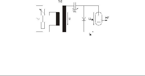
Figure A. Principle drawing of the magnetron control circuit.
At the positive period of the power supply transformer TR2, capacitor C1 will be charged. The charge (Q) of the capacitors depends on the setting of the output power control.
At the negative period the transformer supply voltage and the capacitor voltage are series
Description |
2-2 |
January 2000 |

Enraf-Nonius B.V. |
Radarmed 650 Service Manual |
1409773 |
|
|
|
connected and therefore added. At a voltage of ± -2.6kV the magnetron ignites, an anode current will flow and H.F. energy is emitted. The capacitor C1 will discharge. When the voltage exceeds -2.6kV the magnetron cuts-off.
The emitted H.F. power is also depending on the hight of the supplied high voltage at transformer TR2. The higher the voltage at the secondary side of TR2, the higher the voltage on the capacitor C1 and at the magnetron. The current which flows through the magnetron is in relation with the H.F. emitted energy, during the time that the magnetron is ignited.
The output of the magnetron is connected to a H.F. filter. The directly heated cathode is connected to the secondary winding of transformer TR1. When H.F. energy is emitted high voltage is available at the heater connections of the magnetron with respect to ground (DANGER HIGH VOLTAGE !!).
Description |
2-3 |
January 2000 |

Enraf-Nonius B.V. |
Radarmed 650 Service Manual |
1409773 |
|
|
|
Description |
2-4 |
January 2000 |
 Loading...