

Enraf Tanksystem HERMetic UTImeter Rtex Operation And Service Manual
50455/RTEX/0807 1 UTImeter Rtex
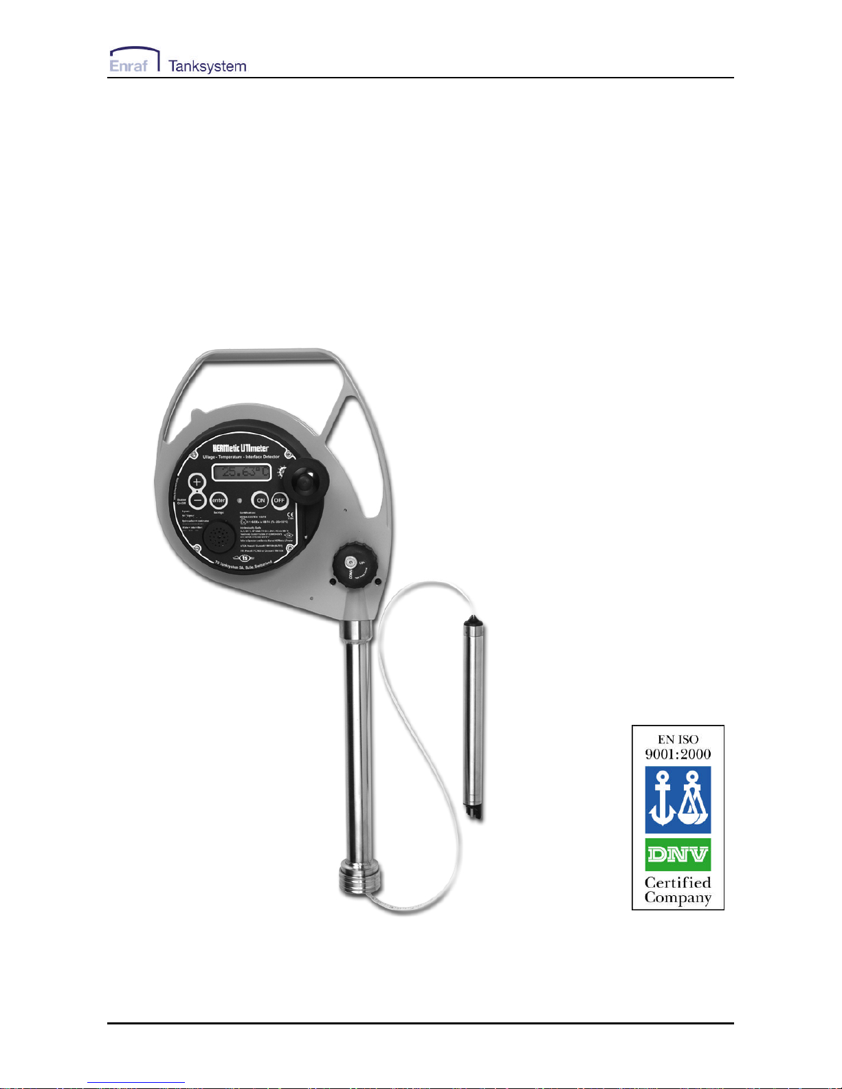
Operation and Service Manual
for HERMetic UTImeter Rtex
Connectors Q1 and Q2
Portable Electronic Restricted Gauging Device
Ullage - Temperature - Interface detector
Note : before using the
instrument please
read this book.
50455/RTEX/0807 2 UTImeter Rtex
1. Table of contents
1. TABLE OF CONTENTS .................................. 2
2. GENERAL INFORMATION ........................... 4
2.1 SHIPMENT NOTE............................................ 4
2.2 INITIAL INSPECTION....................................... 4
2.3 DOCUMENTATION DISCREPANCIES................ 4
2.4 WARRANTY .................................................. 4
2.5 CERTIFICATION............................................. 5
2.6 SPARE PARTS ................................................ 5
2.7 SERVICE AND REPAIR ................................... 5
3. WORLDWIDE SERVICE STATIONS
NETWORK ................................................................ 7
4. RECOMMENDATION FOR S AFE USE........ 9
5. FUNCTIONS - KEY FEATURES.................. 10
6. DESCRIPTION................................................ 11
6.1 GENERAL.................................................... 11
6.2 ULTRASENSINGPROBE ............................. 13
6.2.1 Introduction ....................................... 13
6.2.2 Ullage detection................................. 13
6.2.3 Interface detection ............................. 14
6.2.4 Temperature measurement................. 14
6.3 TAPE........................................................... 15
6.4 TAPE PROTECTION ...................................... 16
6.5 READING INDEX.......................................... 17
6.6 TAPE CLEANER ........................................... 18
6.7 ADDITIONALLOAD (OPTION)...................... 19
6.7.1 Viscous liquids (> 800 Cst)................ 19
6.7.2 Reference height and innage.............. 19
6.8 OTHERS ...................................................... 19
7. EXAMPLES OF INSTALLATION OF THE
GAUGING SYSTEM .............................................. 20
7.1 GENERAL.................................................... 20
7.2 EXAMPLE OFINSTALLATION ON APIPE,
CONNECTOR Q2...................................................... 21
7.3 EXAMPLE OF INSTALLATIONON THE DECK,
CONNECTOR Q2...................................................... 22
7.4 EXAMPLE OFINSTALLATION ON APIPE,
CONNECTOR Q1...................................................... 23
7.5 EXAMPLE OFINSTALLATION ON THEDECK,
CONNECTOR Q1...................................................... 24
8. OPERATION ................................ ................... 25
8.1 BASIC RULES CONCERNING THE5-KEY
CONTROL PAD......................................................... 25
8.2 SELECTING THE LANGUAGE......................... 26
8.3 SELECTING THE TEMPERATURE SCALE ........ 27
8.4 SELECTING THE TEMPERATURE RESOLUTION
28
8.5 ACTIVATINGTHE LED ................................ 29
8.5.1 Temporary setting of the LED ............ 29
8.5.2 Permanent setting of the LED ............ 29
8.6 MUTING THEBUZZER .................................. 30
8.7 BACKLIGHT................................................. 30
8.8 CHECKING THE FUNCTIONS BEFORE USING THE
INSTRUMENT........................................................... 31
8.8.1 Battery................................................ 31
8.8.2 Temperature ....................................... 31
8.8.3 Ullage................................................. 31
8.8.4 Interface ............................................. 31
8.9 INSTALLATION OF THE INSTRUMENT............32
8.10 ULLAGE / INTERFACE MEASUREMENT .........32
8.11 REFERENCE HEIGHT / INNAGE MEASUREMENT
33
8.12 TEMPERATURE MEASUREMENT................... 34
9. CARE AND MAINTENANCE ....................... 35
9.1 CARE ..........................................................35
9.2 CHECKING THE BATTERY ............................36
9.2.1 Before starting gauging ..................... 36
9.2.2 During gauging .................................. 37
9.3 BATTERY REPLACEMENT ............................38
9.4 TAPE REPLACEMENT................................... 39
9.4.1 Disconnecting the tape from the sensor
39
9.4.2 Disconnecting the tape from the
electronic box ..................................................... 39
9.4.3 Disconnecting the tape from the reel
axle 40
9.4.4 Removing the tape from the frame ..... 40
9.4.5 Mounting the new tape ....................... 40
9.5 SENSING PROBE REPLACEMENT................... 41
9.5.1 Disconnecting the old sensing probe . 41
9.5.2 Connecting the new sensing probe..... 41
9.6 TAPE WIPERS REPLACEMENT AND REMOVING
OF TAPE COVER....................................................... 42
9.7 DISPLAY UNITREPLACEMENT...................... 43
9.7.1 Disconnecting the old display unit ..... 43
9.7.2 Connecting the new display unit ........ 43
9.8 VERIFICATIONAND CERTIFICATION OF TAPES
43
9.9 VERIFICATIONAND ADJUSTMENT OF THE
READINGINDEX....................................................... 44
9.10 TEMPERATURE VERIFICATION..................... 45
9.10.1 Equipment required............................ 45
9.10.2 Preparing the Ice Point bath.............. 45

50455/RTEX/0807 3 UTImeter Rtex
9.10.3 Checking the UTImeter...................... 45
9.11 ULLAGE/INTERFACE VERIFICATION............. 46
9.12 ELECTRICALCHECKING OF THETAPE
ASSEMBLY.............................................................. 47
9.13 VISUALINSPECTION FOR DAMAGEDOR
MISSINGPARTS........................................................ 48
9.14 COATED ALUMINIUM PARTS........................ 48
9.15 WINDING ACTION BECOMING STIFF ............. 48
10. TROUBLE SHOOTING ............................. 49
10.1 SAFETY WARNING....................................... 49
10.2 POWER SUPPLY TROUBLES.......................... 49
10.3 TRANSMISSION TROUBLES .......................... 49
10.4 ULLAGE AND/OR INTERFACE TROUBLES..... 50
10.5 TEMPERATURE TROUBLES .......................... 50
11. SPECIFICATIONS................................ ...... 51
12. SPARE PARTS ............................................ 52
12.1 HOW TO PROCEED....................................... 52
12.2 LIST OFPARTS DESCRIPTIONS...................... 52
12.3 SPARE PARTS DRAWINGS............................. 54
13. VALVES DRAWINGS & DECLARATION
OF CONFORMITY ................................................ 63
13.1 VALVES ...................................................... 63
13.2 DECLARATION OF CONFORMITY.................. 63
50455/RTEX/0807 4 UTImeter Rtex
2. General information
2.1 Shipment note
The following parts should be included in the
shipment:
- 1 instrument fitted out with one battery in the
display;
- 1 set of 4 Allen keys: 1.5, 2, 2.5 and 3 mm;
- 1 Operation and Service Manual.
2.2 Initial inspection
Check the contents of the shipment for
completeness and note whether any damage has
occurred during transport. Carry out the “Initial test
before installing the instrument” to verify the good
functioning. If the contents are incomplete, or if
there is a damage, not use the device. A claim
should be filled with the carrier immediately, and
Enraf Tanksystem SA Sales or Service
organization should be notified in order to facilitate
the repair or replacement of the instrument.
2.3 Documentation discrepancies
The design of the instrument is subject to
continuous development and improvement.
Consequently, the instrument may incorporate
minor changes in detail from the information
contained in the manual.
2.4 Warranty
Two (2) years after installation but max. 30
months after delivery ex works except
batteries.
The Vendor undertakes to remedy any defect
resulting from faulty design materials or
workmanship. The Vendor's obligation is
limited to the repair or replacement of such
defective parts by his own plant or one of his
authorized service stations. The Purchaser
shall bear the cost and risk of transportation
of defective parts and repaired parts supplied
in replacement of such defective parts.
When returned to Enraf Tanksystem SA or any
of its agreed Service Stations equipment must
be contamination -free. If it is determined that
the Purchasers equipment is contaminated, it
will be returned to the Purchaser at the
Purchasers expense. Contaminated equipment
will not be repaired, replaced, or covered
under any warranty until such time that the
said equipment is decontaminated by the
Purchaser.
The Purchaser shall notify by fax, telex or in
writing of any defect immediately upon discovery,
specifying the nature of the defect and/or the
extend of the damage caused thereby.
Where no other conditions have been negotiated
between the Vendor and the Purchaser "General
Conditions 188" of United Nations shall apply.
This instrument has been certified as Intrinsically
Safe Instrumentation for only those classes or
categories of hazardous areas stated on the
instrument label, bearing the mark of the
applicable approval authority. No other usage is
authorized.
Unauthorized repair or component replacement by
the Purchaser will void this guarantee and may
impair the intrinsic safety of the instrument. In
particular it is not allowed to repair electronic
circuits.
In no event shall Enraf Tanksystem SA be liable
for indirect, incidental or consequential loss or
damage or failure of any kind connected with the
use if its products or failure of its products to
function or operate properly.
Enraf Tanksystem SA do not assume the
indemnification for any accident or damage
caused by the operation of its product and the
warranty is limited to the replacement of parts or
complete goods.

50455/RTEX/0807 5 UTImeter Rtex
2.5 Certification
The equipment has been approved for the
electrical intrinsic safety by the following
authorities :
ATEX
II 1 G EEx ia IIB T4 / Tamb. 50 °C
Factory Mutual (FM Approvals)
CL I, DIV 1, GP C&D, T4 Tamb. 50 °C and
CL I, ZN 0, AEx ia IIB T4 Tamb. 50 °C
The equipment has been approved as oil/water
interface detector according to MARPOL
Resolution MEPC.5(XIII) of 13 June 1980 by
National Maritime Authorities and/or Classification
Societies.
If you need a copy of any of these certificates
please contact:
Enraf Tanksystem SA
Rue de l'industrie 2
1630 Bulle, SWITZERLAND
Telephone : +41-26-91 91 500
Telefax : +41-26-91 91 505
Web site : www.tanksystem.com
E-mail : info@tanksystem.com
2.6 Spare parts
When ordering spares identify the spare part by
TS number and description. Refer to section
“Drawings”.
Some spares might be repairable; in this case
send the part(s) to any authorised service center
or to the factory.
In case of urgency, complete replacement units
can be made available. Contact the factory or
nearest Service Station for details.
2.7 Service and Repair
The customer is responsible for any freight and
customs clearance charges. If units are sent on a
"freight collect" the charges will be invoiced to the
customer.
When returning units or parts for repair to the
factory please fill out a service request form (see
next page). The serial number (letter "R" followed
by 5 digits) is printed on the identification plate as
shown on the Figure 6-1.
When returned to Enraf Tanksystem SA
equipment must be contamination-free. If it is
determined that the customers equipment is
contaminated, it will be returned to the
customer at the customers expense.
Contaminated equipment will not be repaired
until such time that the customer
decontaminates the said equipment.
Enraf Tanksystem SA is an
ISO 9001 certified company
by Det Norske Veritas
Certification GmbH.
50455/RTEX/0807 UTImeter Rtex
6
Service Request
Customer's address: ..............................................................................
................................................................................................................
................................................................................................................
................................................................................................................
................................................................................................................
Telephone: ..............................................................................................
E-mail: .....................................................................................................
Fax: .........................................................................................................
Type of unit or part: .................................................................................
.................................................................................................................
Serial number: .........................................................................................
Short description of trouble: .....................................................................
..................................................................................................................
..................................................................................................................
..................................................................................................................
Do you want a quotation before repair is started:..........yes / no.............
Repaired unit has to be returned to the following address:
..................................................................................................................
..................................................................................................................
..................................................................................................................
..................................................................................................................
..................................................................................................................

50455/RTEX/0807 UTImeter Rtex
7
3. Worldwide Service Stations network
The updated list can be found on our website www.enraftanksystem.com
COUNTRY ADDRESS TELEPHONE/FAX/E-MAIL
SWITZERLAND ENRAF TANKSYSTEM SA Tel : +41-26-91 91 500
2, rue de l'Industrie Fax : +41-26-91 91 505
CH-1630 BULLE info@tanksystem.com
CANADA PYLON ATLANTIC Tel : +1-902-4683344
A Div. Of Pylon Electronics Inc. Fax : +1-902-4681203
31 Trider Crescent., halifax_csr@pylonelectronics.com
DARTMOUTH, N.S. B3B 1V6
CHINA HUA HAI EQUIPMENT &
ENGINEERING CO LTD
Tel : +86-21-68183183
Factory 7, Lane 1365, East Kang Qiao
Road
Fax : +86-21-68183115
Kang Qiao Industrial Zone, Pu Dong huahaish@huahaiee.com
SHANGHAI, P.C. 201315
GREECE SPANMARIN Tel : +30-210-4294498
86, Filonos Street Fax : +30-210-4294495
GR-185 36 PIRAEUS spanmarin@ath.forthnet.gr
JAPAN DAIWA HANBAI CORPORATION LTD Tel : +81-6-64714701
10-31, Mitejima 2-Chome,
Nishiyodogawa-ku
Fax : +81-6-64729008
daiwa471@silver.ocn.ne.jp
OSAKA 555-0012
KOREA World Ocean CO., LTD
Hang-Woon Building
1168-11, Cho Ryang 3 Dong
Dong-Ku
PUSAN
Tel : +82-51-462-2554/5
Fax : +82-51-462-0468
marine@worldocean.co.kr
MEXICO URBAN S.A. DE C.V.
Ave. Ejército Mexicano 1902
Col. Loma del Gallo
89460 CD.MADERO, TAMPS. MEXICO
Tel : +52-833-2170190
Fax : +52-833-2170190
E-mail : urbansa@prodigy.net.mx
NETHERLANDS B.V. TECHNISCH BUREAU
UITTENBOGAART
Tel : +31-10-4114614
Fax : +31-10-4141004
Brugwachter 13 info@tbu.nl
NL-3034 KD ROTTERDAM

50455/RTEX/0807 UTImeter Rtex
8
The updated list can be found on our website www.enraftanksystem.com
COUNTRY ADDRESS TELEPHONE/FAX/E-MAIL
PORTUGAL CONTROLIS Tel : +351-21-2740606
Soc. Com. Equipamentos de Controlo,
Lda.
Fax : +351-21-2740897
controlis@netc.pt
Rua Conceiçao Sameiro Antunes, 26E
P-2800 COVA DA PIEDADE
RUSSIA NPP "GERDA" Tel : +7-495-7558845
Vilisa Latsisa str. 17
Building 1
Fax : +7-495-7558846
info@gerda.ru
125480 MOSCOW
SINGAPORE HUBBELL INT'L (1976) PTE LTD Tel : +65-6-2557281
322 Thomson Road Tel : +65-6-2550464
SINGAPORE 307665 Fax : +65-6-2532098
hubbell@mbox2.singnet.com.sg
SPAIN E.N.I. Tel : +34-94-4746263
Electronica y Neumatica Industrial, S.A. Fax : +34-94-4745868
C/Jon Arrospide, 20 (Int.) eni.tecnica@eni.es
48014 BILBAO
SWEDEN INSTRUMENTKONTROLL Tel : +46-31-240510
Lars Petersson AB Tel : +46-31-240525
Varholmsgatan 1 Fax : +46-31-243710
414 74 GÖTEBORG Info@instrumentkontroll.se
UNITED ARAB
EMIRATES
MARITRONICS TRADING L.L.C.
P.O. Box 6488
Shed # 72, Jadaf Ship Docking Yard
Tel : +971-4-3247500
Fax :+971-4-3242500
maritron@emirates.net.ae
DUBAI
UNITED
KINGDOM
ENERGY MARINE (INTERNATIONAL)
LTD.
12 Clipstone Brook Industrial Estate
Cherrycourt Way
LEIGHTON BUZZARD, BEDS LU7 8TX
Tel : +44-1525-851234
Fax :+44-1525-852345
info@engmar.com
U.S.A/ HERMETIC, INC. Tel: +1-281-930 1777
TEXAS 4522 Center Street Fax: +1-281-930 1222
DEER PARK, TX 77536 Toll free call in the USA:
1-800-900 1778
info@hermeticinc.com
50455/RTEX/0807 UTImeter Rtex
9
4. Recommendation for safe use
1. This Operation and Service Manual is a guide in order to help the user to operate the instrument to our
best knowledge.
2. Nevertheless the maker disclaims all responsibility and liability for damage resulting from the use of the
equipment regardless of the cause of the damage.
3. Attention is drawn to the possible hazard due to electrostatic charges which may be present in the
tank. This may happen in particular with static accumulator liquids, i.e. liquids which have low conductivity
of 50 picoSiemens/metre (pS/m) or less.
4. It is very important that the instrument is grounded to the tank before the probe is introduced into
the tank and remains grounded until after complete withdrawal from th e tank.
4.1. If the instrument is installed with the quick connect coupler, grounding is effected through the quick
connect coupler and the mating nipple of the valve provided that these parts are kept clean and free
from corrosion in order to guarantee electrical conductivity. If a grease is used for this purpose, it
must be one which contains graphite.
4.2. If the instrument is not connected to the mating deck valve, the instrument has to be also earthed by
means of the grounding cable and clamp.
5. It is anticipated that the user will have specific operating methods laid down to ensure safety
when using this type of apparatus. In this case the user's instructions shall be strictly observed.
6. In the absence of such instructions the following should be noted:
6.1. If a metal sounding pipe is fitted beneath the deck valve or tank is inerted, then ullaging, etc. is
permissible at any time with no restriction.
6.2. If there is no sounding tube or tank is not inerted, the following precautions shall be taken:
6.2.1. If the cargo is not a static accumulator liquid, i.e. its conductivity is more than 50 pS/m, then
ullaging is permitted provided that the instrument is properly grounded and earthed before
the probe is inserted into the tank and remains earthed until the probe has been removed
from the tank.
6.2.2. If the cargo is a static accumulator liquid, i.e. its conductivity is less than 50 pS/m, then
ullaging is permitted provided that:
6.2.2.1. The instrument is properly grounded and earthed before the probe is inserted into
the tank and remains earthed until the probe has been removed from the tank.
6.2.2.2. The apparatus is not introduced into a tank until at least 30 minutes have elapsed
after completion of any loading operation or stopping the injection of inert gas.
6.3. For further guidance refer to International Safety Guide for Oil Tankers and Terminals (ISGOTT),
ISBN 1 85609 081 7, Fith Edition 2006, or consult the appropriate Legislative Authority for the
installation.
7. Warning: change of battery must be carried out in safe area only (non flammable atmosphere).

50455/RTEX/0807 UTImeter Rtex
10
5. Functions - Key Features
This HERMetic instrument is a portable multiple
functions gauging system that is designed to
perform under restricted conditions in a single
operation 3 measurements:
a) Ullage (outage). Optionally innage is available¹.
b) Oil/water Interface level.
Tape resolution: 1 mm (1/16 ")
Tape accuracy: ±3.2 mm for 30 m
(±1/8 " approx. for 100 feet)
Ullage/interface detection accuracy:
±2 mm (±0.08 " approx.)
Minimum detectable tank bottom interface or liquid
level: 4 mm (0.16" approx.).
c) Temperature by continuous reading at any
level.
Ambient temperature range: -20°C to 50°C
( -4°F to 122°F)
Sensor measurement range:-40°C to 90°C
( -40°F to 194°F)
Resolution: 0.01° or 0.1°, selectable
Accuracy over calibration range: ±0.1°C (0°C to
70°C); ±0.2°F (32°F to 158 °F)
Temperature reading: °C or °F, selectable.
This HERMetic device meets the requirements of
API MPMS Chapter 7 2001, table 3, ISO 4268 and
IP PMM Part IV.
Thanks to the small diameter of the sensing probe
this instrument can be used with valves of
diameters down to 25 mm (1”) only.
A tape protection tube prevents closing the valve
on the tape through inadvertence.
¹ An additional device, usable with 2” valves only,
can be provided that allows Reference Height
and Innage measurement. Available on “Visc”
models.
Tank top
Ullage level
Interface level
Water
Product
Vapour
Tape protection
Zero reference level
50455/RTEX/0807 UTImeter Rtex
11
6. Description
6.1 General
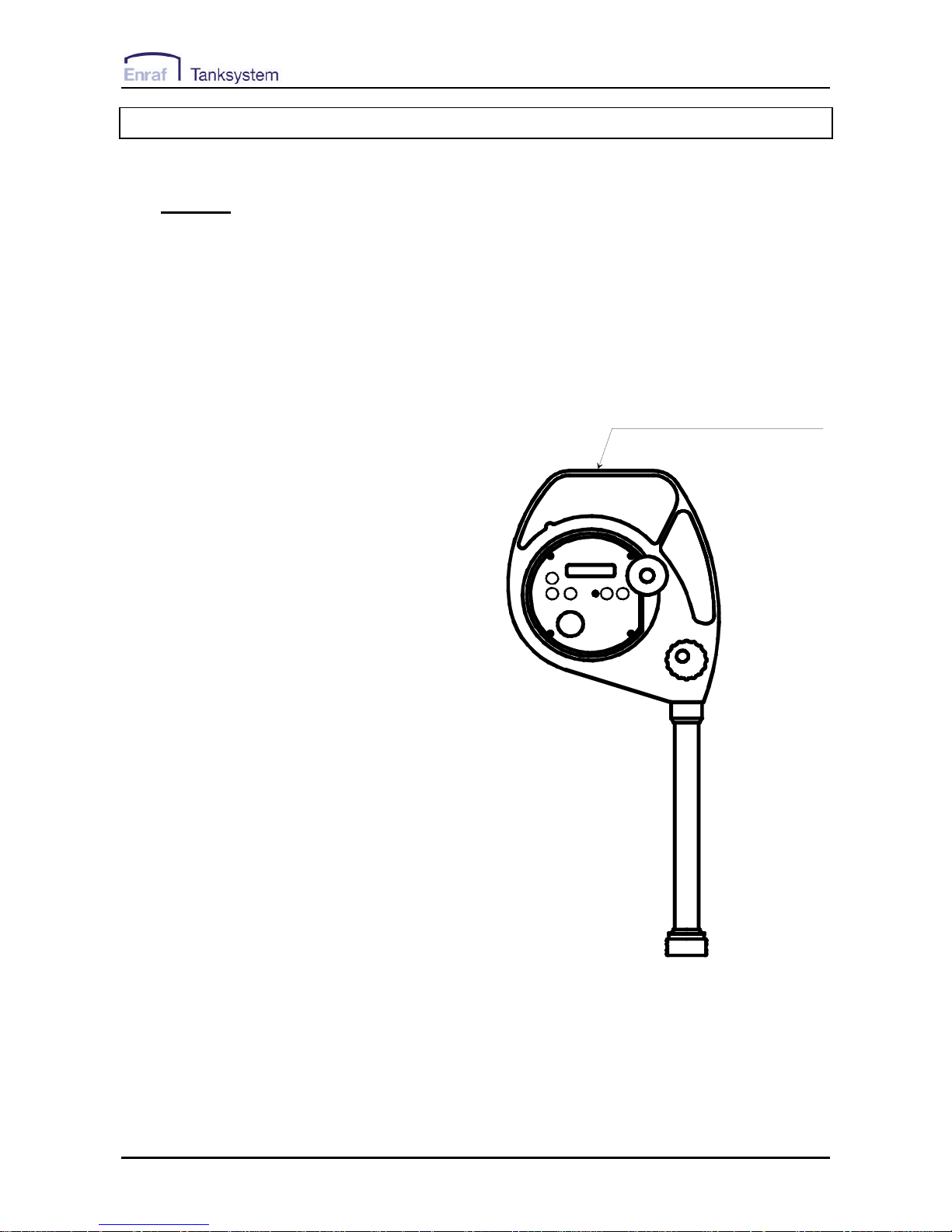
Each HERMetic instrument is individually
identified with a 6 digits serial number starting
with the letter R, example R10058. This serial
number is printed on the identification plate as
shown on Figure 6-1.
The HERMetic instrument is fitted with an ULTRA
sensing probe.
The unit emits control beep, continuous beep and
intermittent beep.
When the sensing probe is surrounded by air, a
control beep occurs every 2 sec.
When the sensing probe is in contact with any
petroleum product, the beep is continuous.
When the sensing probe is in contact with water
the beep is intermittent.
Control beep
• •
Continuous beep • • • • • • • • • •
Intermittent beep • • • • • •
A light signal (LED) can also be activated that
blinks at the same frequency as the buzzer tones.
This can be useful in noisy environments or at
night.
A backlight can be used at night to light up the
display.
The HERMetic instrument is powered by a 9 Volt
battery stored in the electronic terminal named
instrument unit. Current consumption is very low,
ensuring long operation without battery
replacement. A continuous tone means that the
battery needs replacement. If the battery power
is too low, it is no more possible to read the
temperature.
Maintenance is easy because design is modular
and allows quick exchange of parts.
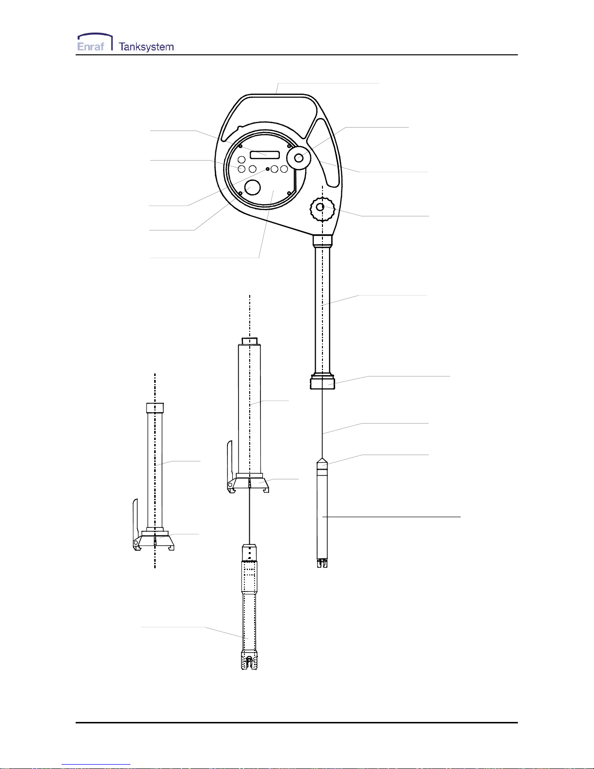
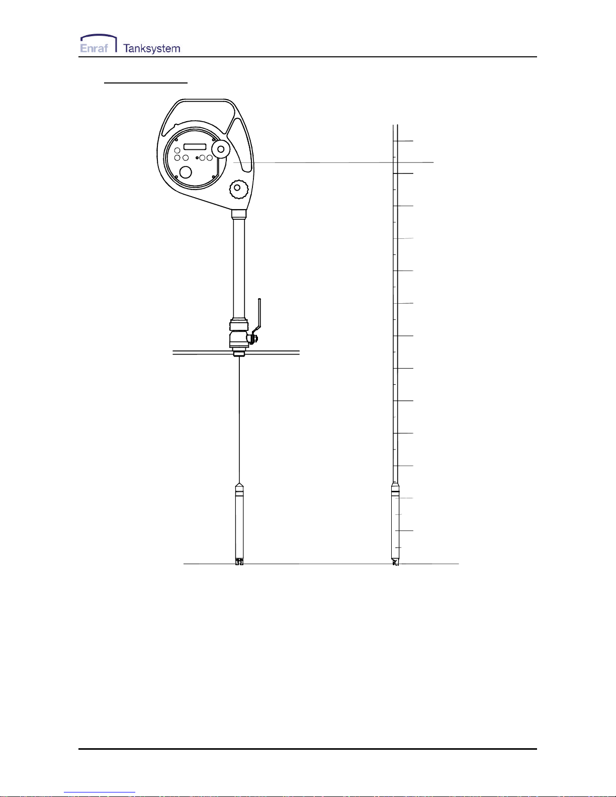
See also Figure 6-2 to get to know the equipment.
identification plate
serial number
Figure 6-1
50455/RTEX/0807 UTImeter Rtex
12
Storage tube SS1
Quick connector Q1
Tape cleaner
Reading index
Buzzer
Tape
Sensing probe ULTRA
Tape adaptor
Display
SS1
SS2
Q2
Q2
Visc
device for
innage measurement
Display unit
LED
Identification plate
Crank
5 keys pad
Figure 6-2
50455/RTEX/0807 UTImeter Rtex
13
6.2 ULTRA sensing probe
6.2.1 Introduction
The ULTRA sensing probe consists of a
stainless steel tube terminated by a hightech plastic head which cannot be
removed from the tube. The sensing
probe includes an ultrasonic liquid level
sensor, a temperature sensor and a
conductivity electrode. The sensitivity for
ullage and interface measurement is not
adjustable. The temperature
measurement is calibrated at the factory
and does not require subsequent
adjustment.
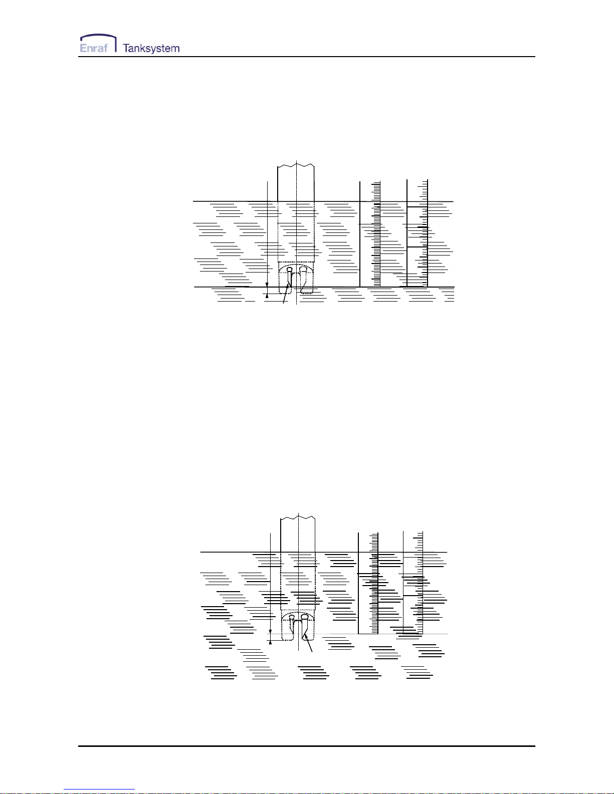
6.2.2 Ullage detection
The ullage detector consists of two
piezoceramic plates and electronic
circuits. When the sensor head is
immersed in a non-conductive liquid (oil or
petroleum), the emitted ultrasonic signal is
detected by the receiver, coded and sent
to the instrument unit which activates the
buzzer with the continuous beep.
1
60 1 2 3 4 5
0
1
1 2
1
Reaction point
Ultrasonic level sensor
4 mm
Air
Liquid
Figure 6-3
The reaction point is located 4 mm (5/32") from the sensor bottom and identical with the zero-point of the tape graduation.
50455/RTEX/0807 UTImeter Rtex
14
6.2.3 Interface detection
The principle consists of a conductivity
measurement between an active
electrode and a grounded electrode.
When the liquid is conductive (as water),
the ullage sensor detects the presence of
the liquid as well and the conductivity
electrodes and associated electronic
circuits modulate the coded signal to
generate the intermittent beep.
1
60 1 2 3 4 5
0
1
1 2
1
Interface level
Interface sensor
4 mm
Water
Oil
Air
Oil
Figure 6-4
The reaction point is located 4 mm (5/32") from the sensor bottom and identical with the zero-point of the tape graduation.
6.2.4 Temperature measurement
The sensing element is a Platinum Resistance
Temperature Detector (RTD) element. The
element is located in the temperature electrode,
which is filled in with a heat transfer compound
paste to reduce the response time.
The RTD element signal is digitized, and then all
errors (offset, non-linearity and drift) are corrected
and compensated by the micro-controller located
in the sensor probe. The RTD element
characteristics are stored in the sensor memory
and are dedicated to one sensor. For this reason,
changing a sensor does not require a new
calibration.
All data are serialised and sent by the microcontroller to the Display Unit.
Temperature settings (resolution, scale) are easy
to select by pressing the 5-key control panel.
1
60 1 2 3 4 5
0
11 21
Temperature level
Temperature sensor
4 mm
Liquid
Air
Figure 6-5
The reaction point is located 4 mm (5/32") from the sensor bottom and identical with the zero-point of the tape graduation.
50455/RTEX/0807 UTImeter Rtex
15
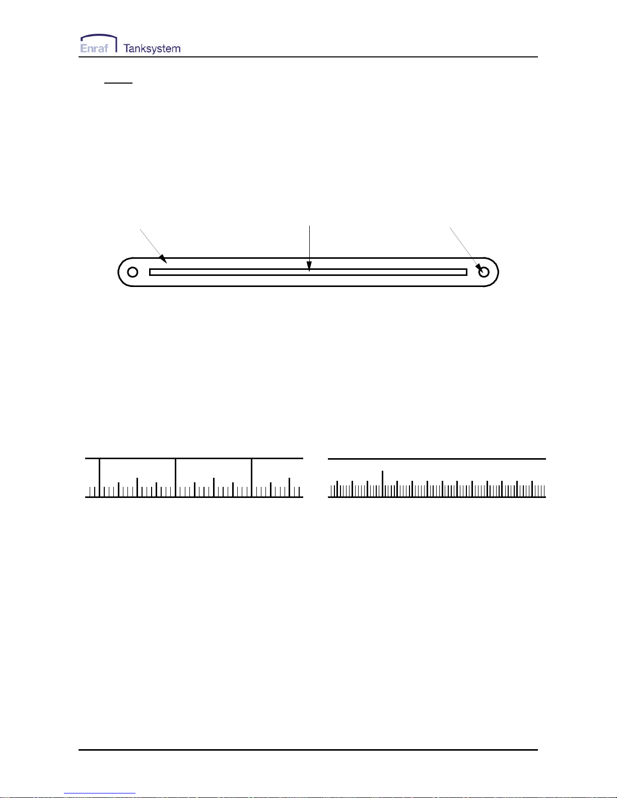
6.3 Tape
The ETFE (TEFZEL) coated tape provides 3 main
functions :
It holds the sensing probe.
It is graduated and therefore makes it possible
to determine the distance between the reaction
point and the reading index. If the reading
index is set up at the zero ullage level, the
reading of the tape is identical to the ullage.
It contains 2 wires for transmitting the signal
and the power between the display unit and the
probe. The steel tape itself is used as a
grounding wire between the sensing probe
tube and the display unit.
TEFZEL
STEEL TAPE
WIRE
Figure 6-6
The standard graduation is a double side type that shows the metric graduation on one side and the inch one
on the other side. The tape is mounted on the equipment according to the need.
3 4
23
10 11 12 13 14 15
7
7
5
23
9
23
metric sideinch side
Figure 6-7
50455/RTEX/0807 UTImeter Rtex
16
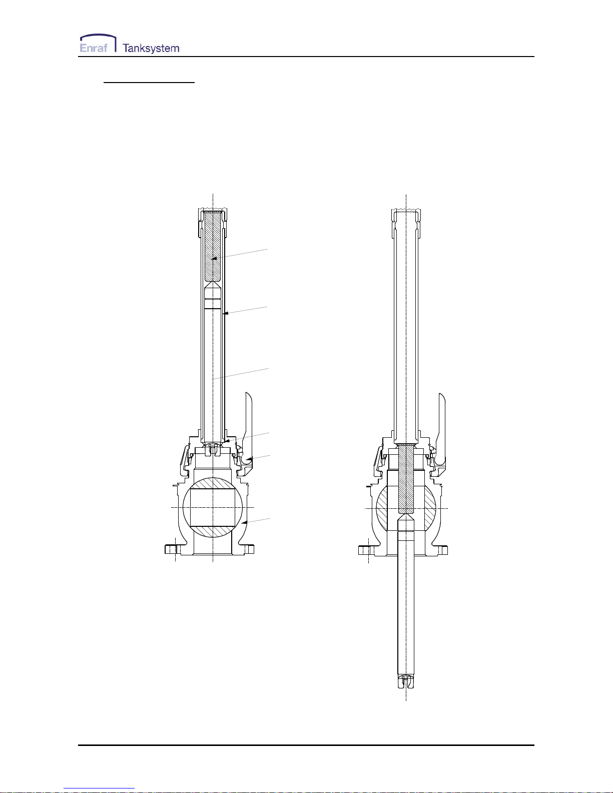
6.4 Tape protection
The tape protection tube is a mechanical safety
device which prevents the valve from being closed
as long as the sensing probe is inside the tank.
When the sensing probe is lowered the protection
tube will follow the sensing probe by gravity until
the tube is retained by a ring located inside the
coupler. In that position the protection tube
prevents closing the valve. When the tape is
wound up the protection tube will stay in position
until it is pushed up by the sensing probe. Before
instrument is used check that the protection tube
is moving freely. For cleaning purposes the
protection tube is slotted.
VALVE CLOSED
VALVE OPEN
TAPE PROTECTION TUBE
STORAGE TUBE
SENSOR
RETAINER
QUICK CONNECT
COUPLER
BALL VALVE
Figure 6-8
50455/RTEX/0807 UTImeter Rtex
17
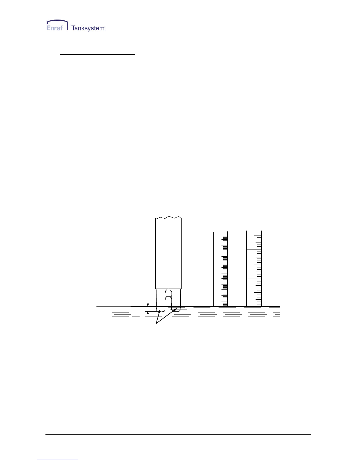
6.5 Reading index
Zero ullage
Reference level of tank
Liquid level
Reaction point
100
200
300
400
500
600
700
800
900
1000
1100
1200
0
1300
Figure 6-9
The tape reading at the height of the reading index
of the instrument is indicating the distance
between the reaction point and the reading index.
If the instrument is installed in such a way that the
reading index is at the same level as the zeroullage reference level the reading of the tape
corresponds to the ullage providing the reaction
point of the sensing probe is positioned at the
liquid level.
If the reading index is positioned below or above
the reference level a positive or negative
correction of the tape reading is necessary.
See also chapter 7 “Examples of installation of the
gauging system”.

50455/RTEX/0807 UTImeter Rtex
18
6.6 Tape cleaner
This HERMetic equipment is fitted with a tape
cleaner that helps draining the liquid back to the
tank when rewinding the tape. It is very easy to
operate:
- position "DOWN": the wipers are not working,
the tape is free;
- position "UP": the wipers are cleaning the
tape.
Refer to Figure6-10.
Tape cleaner DOWN = wipers not engaged
Tape cleaner UP = wipers engaged
Figure 6-10

50455/RTEX/0807 UTImeter Rtex
19
6.7 Additional Load (option)
An additional load (see Figure 6-2) on the sensing
probe can be provided for one of the following
reasons. This option is available on UTImeter
Rtex Visc equipped with the storage tube Q2 (2”)
and needs valves of at least 2” size.
6.7.1 Viscous liquids (> 800 Cst)
For gauging viscous liquids the load can
help the sensing probe in penetrating the
liquid and in keeping the tape straight.
6.7.2 Reference height and innage
For measuring the reference height of a
tank and innages the load allows the
sensing probe to touch the dip/datum
plate.
6.8 Others
The tape is coiled on a reel which holds also the
electronic box and the display unit.
The reel is assembled to the electronic box and
can be locked at discrete positions by means of a
stopping mechanism in the crank. Pull the crank to
free the stopping mechanism.
The external reel flange and the frame are made
in aluminium coated with polyamid PA 11
(RILSAN).
The storage tube is threaded to the frame.
The storage tube is equipped with a quickconnector which fits on the HERMetic valves.

50455/RTEX/0807 UTImeter Rtex
20
7. Examples of installation of the gauging system
7.1 General
The gauging system consists of the HERMetic
instrument and the associated HERMetic valve.
Two types of connector can be provided as shown
on Figure 7-1.
Figure 7-1
The following sections, respectively 7.2, 7.3 for
connector Q2 and 7.4, 7.5 for connector Q1,
describe 2 examples for installing the valves and
adjusting the height of the gauging system.
The valves should be installed in such a way that
the zero-ullage level coincides with the reading
index level, so that no correction would be
necessary. For achieving this it may be necessary
to install an adjusting pipe between the deck and
the valve.
If the valves are installed directly on deck or if for
any reason the level of the reading index is below
or above the zero-ullage level, then a correction
table should be used.
There should be no internal tank structure
between the valve outlet and the tank bottom such
that will impede the path of the equipment into the
tank.
All valves shall be installed at the same level.
Small systematic level error can be corrected by
adjusting the reading index accordingly.
When designing the gauging port and to avoid
damaging the tape during rewinding it is advised
to chamfer or to grind all sharp edges (on pipes,
flanges, etc.) that could damage the tape when
operating the gauge.
50455/RTEX/0807 UTImeter Rtex
21
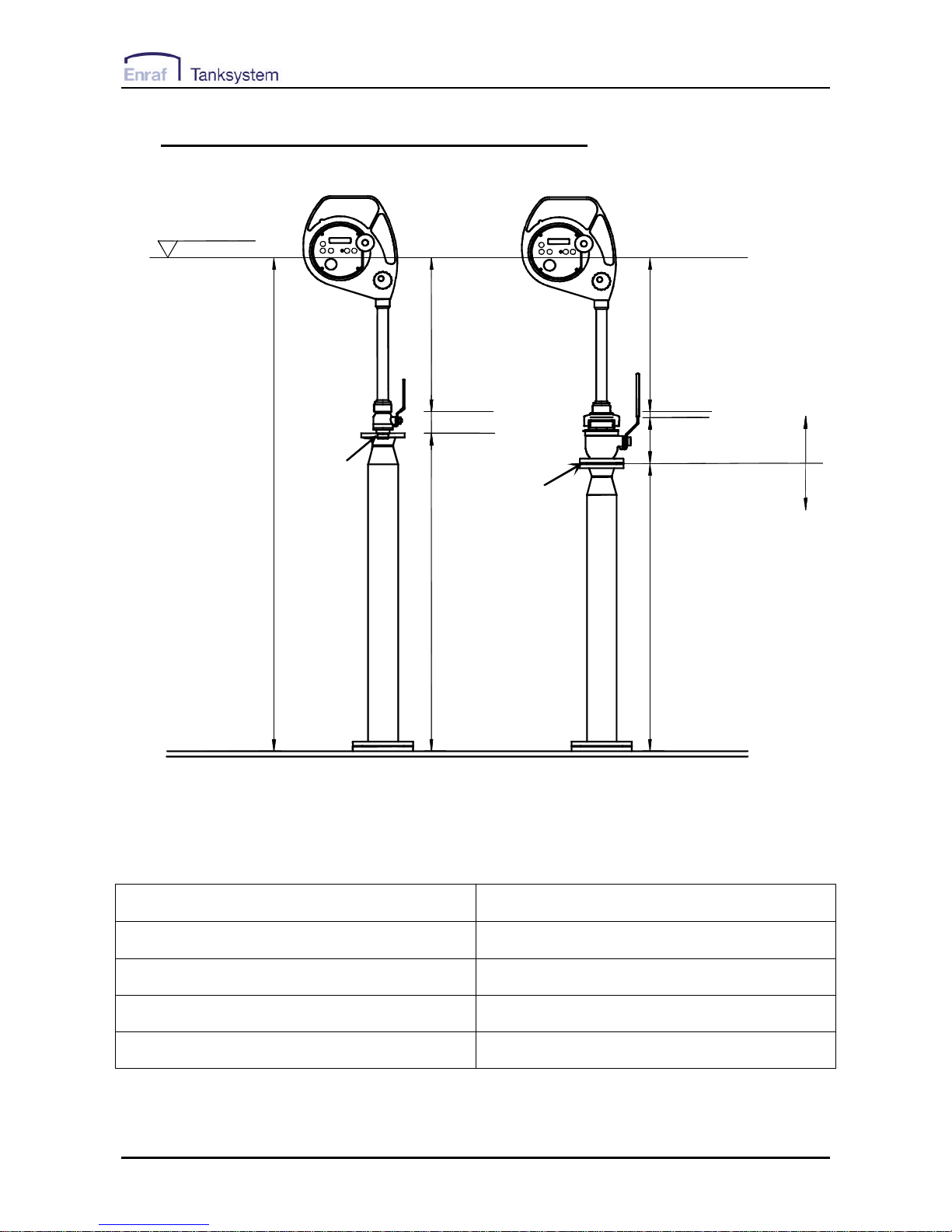
7.2 Example of installation on a pipe, connector Q2
Reading
index
Reading
index
H
460mm 460mm
HV
HV
HC
HT
HT
Tank Zero Ullage level
Thread
Flange
TS supply
Customer supply
SS1 Q1
SS1 Q1
Tank Deck
Figure 7-2
Valve designation C.2-SS; C.2-SS-W; C.2-SS-BL; C.2-SS-SEC
Bottom connection thread or flange
Boring 2”
*) HV (mm) 141
*) HT (mm) H-615
*) Dimension HV is without gasket. If gaskets are used dimension HT is reduced by thickness of gasket.
50455/RTEX/0807 UTImeter Rtex
22
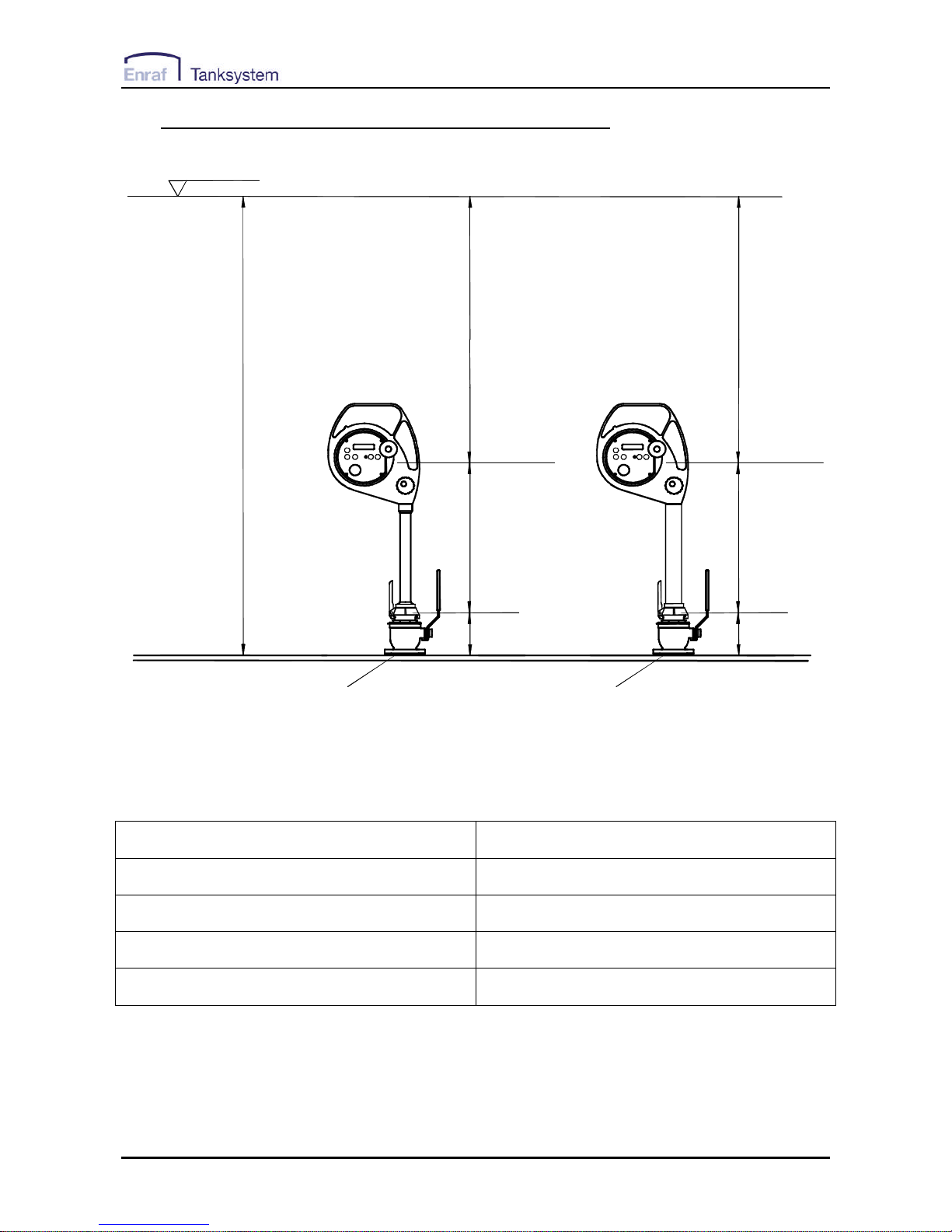
7.3 Example of installation on the deck, connector Q2
Tank Zero Ullage level
Flange
H
Reading
index
474mm
HV
HX
Tank Deck
SS1 Q2
Flange
Reading
index
474mm
HV
HX
SS2 Q2
Figure 7-3
Valve designation C.2-SS; C.2-SS-W; C.2-SS-BL; C.2-SS-SEC
Bottom connection thread or flange
Boring 2”
*) HV (mm) 141
*) HX (mm) H-615
*) Dimension HV is without gasket. If gaskets are used dimension HX is reduced by thickness of gasket.
50455/RTEX/0807 UTImeter Rtex
23
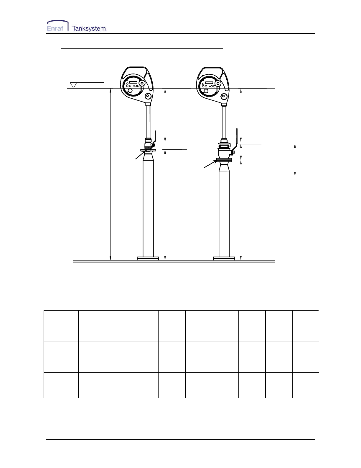
7.4 Example of installation on a pipe, connector Q1
Reading
index
Reading
index
H
460mm 460mm
HV
HV
HC
HT
HT
Tank Zero Ullage level
Thread
Flange
TS supply
Customer supply
SS1 Q1
SS1 Q1
Tank Deck
Figure 7-4
Valve
designation
A.1-SS C.1 -SS C.1-SS C.1-SS C.2-SS
C.2-SS-W
C.2-SS
C.2-SS-W
A.2-SS A.2,5-SS A.4-SS
Boring 1" 1" 1" 1" 2" 2" 2" 2,5” 4”
Bottom
connection
thread thread flange
JIS 5K25
flange
JIS 5K50
thread flange flange flange flange
*) HV (mm) 120 65 79 79 141 141 172 99 140
HC (mm) na na na na 14 14 41 53 58
*) HT (mm) H-580 H-525 H-539 H-539 H-615 H-615 H-673 H-612 H-658
*) Dimension HV is without gasket. If gaskets are used dimension HT is reduced by thickness of gasket.
50455/RTEX/0807 UTImeter Rtex
24
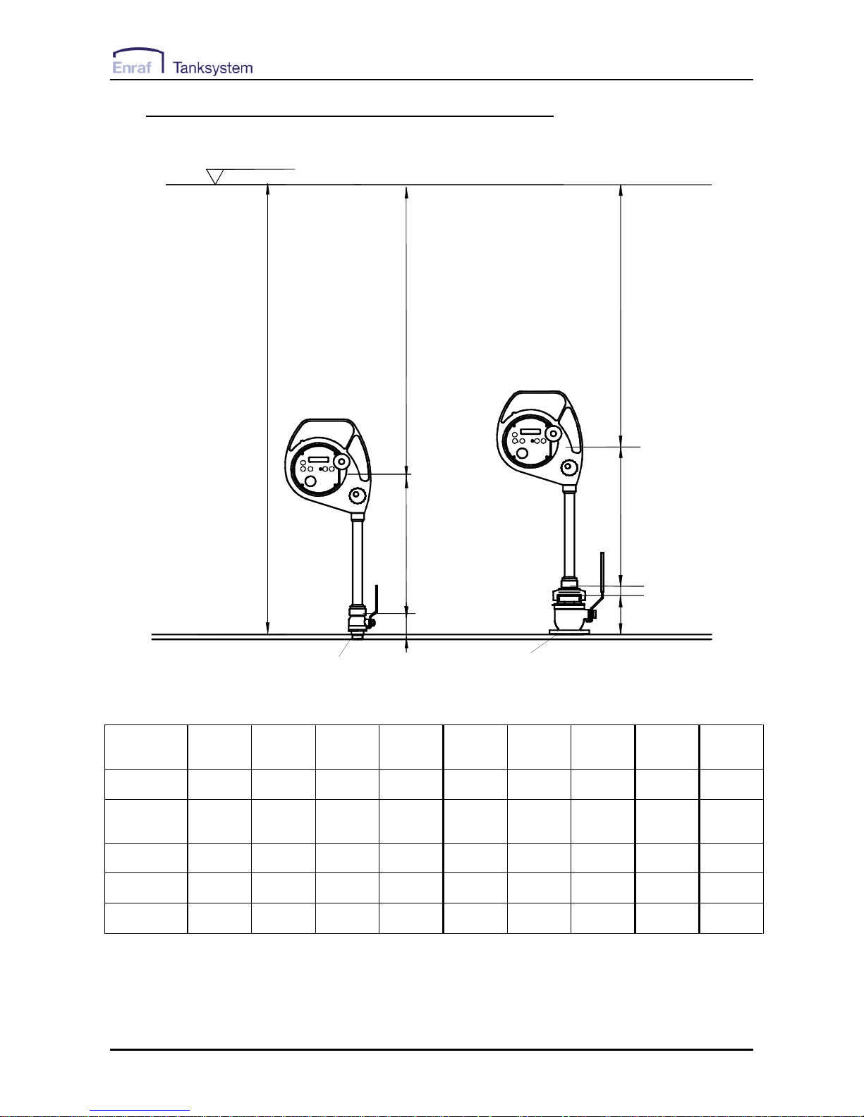
7.5 Example of installation on the deck, connector Q1
Tank Zero Ullage level
Thread Flange
Reading
index
Reading
index
H
HX
HV
HX
HV
460 mm
460 mm
HC
Tank Deck
SS1 Q1
SS1 Q1
Figure 7-5
Valve
designation
A.1-SS C.1 -SS C.1-SS C.1-SS C.2-SS
C.2-SS-W
C.2-SS
C.2-SS-W
A.2-SS A.2,5-SS A.4-SS
Boring 1" 1" 1" 1" 2" 2" 2" 2,5” 4”
Bottom
connection
thread thread flange
JIS 5K25
flange
JIS 5K50
thread flange flange flange flange
*) HV (mm) 120 65 79 79 141 141 172 99 140
HC (mm) na na na na 14 14 41 53 58
*) HX (mm) H-580 H-525 H-539 H-539 H-615 H-615 H-673 H-612 H-658
*) Dimension HV is without gasket. If gaskets are used dimension HX is reduced by thickness of gasket.
 Loading...