

Page 1

1
U P S
1000VA – 3000VA
■
■■
■USER‘S MANUAL■
■■
■
2011/11 v 1.0
Page 2

2
EMC Statements
FCC Part 15
NOTICE: Pursuant to section 15 of the FCC rules, this product has been tested and thereby
complies to the conditions of a Class B (1000VA) and Class A (2000-3000VA) digital device, which
have been established for offering sufficient protection against dangerous interference for
installation in a residential area. Installation and use of the equipment should comply with the
instructions provided in order to avoid such interference due to the amount of radio frequency
energy that is radiated and generated by the equipment. In spite of this, we cannot assure that a
certain amount of interference may not occur in some installations. If, by turning on and off, it can
be deduced that your radio or television reception is found to be influenced by harmful interference
from the equipment, it is recommended to use one of the following preventive measures:
.
Place the receiving antenna in a separate location or orientation.
.
Ensure a greater distance is achieved between the receiver and the equipment.
.
Ensure that your equipment is connected to an outlet on a separate circuit than the receiver.
.
Contact a technician experienced with radio and TV or a dealer for further assistance.
ICES-003
This Class B Interference Causing Equipment meets all requirements of the Canadian Interference
Causing Equipment Regulations ICES–003. Cet appareil numérique de la classe B respecte toutes
les exigences du Reglement sur le matériel brouilleur du Canada.
Declaration of Conformity Request
Units labeled with a CE mark comply with the following standards and directives:
.
Harmonic Standards: EN 50091-1-1, EN 62040-1-1 1st / IEC 62040-1-1 1st and
EN 50091-2 / EN62040-2 1st / IEC 62040-2 1st
.
EU Directives:73/23/EEC, Council Directive on equipment designed for use within
certain voltage limits
93/68/EEC, Amending Directive 73/23/EEC
89/336/EEC, Council Directive relating to electromagnetic compatibility
92/31/EEC, Amending Directive 89/336/EEC relating to EMC
Page 3

3
The EC Declaration of Conformity is available upon request for products with a CE mark.
CONTENTS
1. Introduction............................................................................................ 8
2. System description .................................................................................. 8
2.1 General description ......................................................................................... 8
3. Safety Information ................................................................................ 12
4. Storage ................................................................................................. 13
5. Installation ........................................................................................... 13
5.1 Environment ................................................................................................ 13
5.4 Default settings at the factory ........................................................................ 22
6. Computer and Alarm connections ......................................................... 23
6.1 EPO port (emergency power off) .................................................................... 25
6.2 Load segments (1000 - 3000 VA) ................................................................... 25
7. User’s guide to operations ..................................................................... 26
7.1 Starting and shutting down the UPS ............................................................... 26
7.2 Button Operation .......................................................................................... 26
7.3 Control Panel functions ................................................................................. 27
7.4 Interpreting UPS messages ............................................................................ 31
7.5 Trouble shooting .......................................................................................... 32
8. Maintenance ......................................................................................... 33
9. Technical Specifications ........................................................................ 34
9.1 .1Power Range 1000-3000 VA at P.F 0.8 (LV) (Tower and 19” RM model) ......... 34
9.1.2 Power Range 1000-3000 VA at P.F0.9 (LV) (Tower and 19” RM model) ......... 34
9.2.1 Power Range 1000-3000 VA at P.F 0.8(HV) ................................................. 35
(Tower and 19” RM model) ................................................................................ 35
9.2.2 Power Range 1000-3000 VA at P.F 0.9(HV) ................................................. 36
(Tower and 19” RM model) ................................................................................ 36
10. Manual Bypass Operation…………………………………………………...40
Page 4

4
IMPORTANT SAFETY INSTRUCTIONS
SAVE THESE INSTRUCTIONS
● This Manual Contains Important Instructions that should be Followed during Installation
and Maintenance of the UPS and Batteries.
● The equipment can be operated by any individuals with no previous experience.
●WARNING: Intend for installation in a controlled environment. Maximum ambient
temperature 40°C.
● CAUTION: Risk of electric shock. Refer to top or rear or bottom of UPS for Cautionary
markings.
● CAUTION: Risk of electric shock. Heat sinks are live. Disconnect unit before servicing.
● CAUTION (UPS Having Internal Batteries): Risk of electric shock - Hazardous live
Parts inside this unit are energized from the battery supply even when the input AC power
is disconnected.
● CAUTION (No User serviceable Parts): Risk of electric shock, do not remove cover.
No user serviceable parts inside. Refer servicing to qualified service personnel.
● CAUTION (Non-isolated Battery supply): Risk of electric shock, battery circuit is not
isolated from AC input, hazardous voltage may exist between battery terminals and ground.
Test before touching.
● WARNING (Fuses): To reduce the risk of fire, replace only with the same type and rating of fuse.
● CAUTION: Do not disconnect battery connector under load.
● ATTENTION: Hazardous through electrical shock. Also with disconnection of this unit from the
mains, hazardous voltage still may be accessible through supply from the batteries. The battery
supply should therefore be disconnected in the plus and the minus pole when maintenance or
service work inside the battery cabinet or UPS is considered.
● CAUTION (For any pluggable only): With the installation of this equipment it should be
prevented, that the sum of the leakage current of the UPS and connected consumer does not
Page 5

5
exceed 3.5 mA.
● CAUTION (For permanent connection only): HIGH LEAKAGE CURRENT, Earth connection
essential before connection supply
● WARNING: Intend for installation in a controlled environment.
● CAUTION: Do not dispose of batteries in a fire, the battery may explode.
● CAUTION: Do not open or mutilate the battery, released electrolyte is harmful to the skin and
eyes.
● CAUTION: A battery can present a risk of electric shock and high short circuit current.
The following precaution should be observed when working on batteries
A. Remove watches, rings or other metal objects.
B. Use only tools with insulated handles.
C. Wear rubber gloves and boots.
D. Do not lay tools or metal parts on top of batteries.
E. Disconnect charging source prior to connecting or disconnecting battery terminals.
To reduce the risk of electric shock, disconnect the UPS from the mains supply before installing a
computer interface signal cable. Reconnect the powers cord only after signaling interconnections
have been made.
Servicing of batteries should be performed or supervised by personnel knowledge of batteries and
the required precautions. Keep unauthorized personnel away from batteries.
● CAUTION: When replacing batteries, replace with the same type and number of batteries:
One Sealed lead acid battery, rated 12 V, 9 AH max.
● CAUTION: To reduce the risk of fire, use only No. 26 AWG or larger telecommunication line
cord.
● CAUTION (FOR 1000-3000VA HV Only) : To reduce the risk of fire. Connect only to a circuit
provided with 20 amperes maximum branch circuit overcurrent protection in accordance with the
National Electric Code, ANSI/NFPA 70”.
● CAUTION (FOR 3000VA with I/P Terminal Block Only) : To reduce the risk of fire. Connect
only to a circuit provided with 30 amperes maximum branch circuit overcurrent protection in
Page 6

6
accordance with the National Electric Code, ANSI/NFPA 70”.
● CAUTION (FOR 1000-2000VA with I/P Terminal Block Only) : To reduce the risk of fire.
Connect only to a circuit provided with 20 amperes maximum branch circuit overcurrent
protection in accordance with the National Electric Code, ANSI/NFPA 70”.
Page 7
7
The instructions contained within this safety manual are deemed important and should be closely
followed at all times during installation and follow-up maintenance of the UPS and batteries.
CAUTION
The unit has a dangerous amount of voltage. If the UPS indicator is on, the unit’s outlets
may have a dangerous amount of voltage even when not plugged into the wall outlet
because the battery may continue to supply power.
Care should be taken to undertake installation indoors free from electrically-conductive
particles which is under temperature and humidity control in order to reduce the risk of
electric shock. It is best to disconnect the device using the power supply cord. Ensure that
the equipment is placed in a position near the outlet where easily accessible. Except
replacing the batteries, all servicing on this equipment must be carried out by qualified
service personnel. Before conducting any maintenance, repair or shipment, first ensure
that everything is turned off completely and disconnected.
For additional safety instructions, please use the Safety Manual as reference.
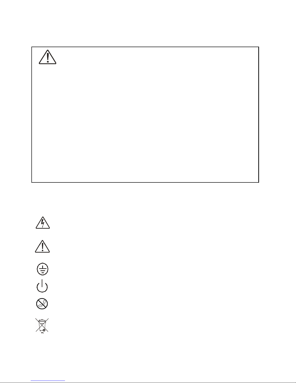
Special Symbols
The following symbols used on the UPS warn you of precautions:
RISK OF ELECTRIC SHOCK – Please observe the warning that a risk of electric shock
is present.
CAUTION: REFER TO OPERATOR’S MANUAL - Refer to the operator’s manual for
additional information, such as important operating and maintenance instructions.
SAFE GROUNDING TERMINAL - Indicates primary safe ground.
LOAD ON/OFF - Pressing this button turns on/off the output receptacles and the Indicator
light.
RJ-45 RECEPTACLE - The receptacle provides network interface connections and
telephone or telecommunications equipment should not be plugged into it.
Please do not discard the UPS or UPS batteries as the UPS may have valve regulated,
lead–acid batteries. Please recycle batteries.
Page 8

8
1. Introduction
The information provided in this manual covers single phase 1000 – 3000 VA, uninterruptible power
systems, their basic functions, operating procedures, and emergency situations, also including
information on how to ship, store, handle and install the equipment. Only detailed requirements of
the UPS units are described herein, and installation must be carried out in accordance with this
manual. Electrical installations must also carefully follow local legislation and regulations. Only
qualified personnel should conduct these installations as failure to acknowledge electrical hazards
could prove to be fatal.
2. System description
Several different kinds of sensitive electrical equipment stay protected by a UPS (Uninterruptible
Power System) including computers, workstations, process control systems, telecommunications
systems, sales terminals, other critical instrumentation, etc. The purpose of the UPS is to protect
these systems from poor quality utility power, complete loss of power, or other associated problems.
Electrical interference abounds in many forms causing problems in AC power, from lightning,
power company accidents and radio transmissions to motors, air conditioners, and vending
machines, among others. So protection of sensitive electrical equipment is vital to protect against
power outages, low or high voltage, slow voltage fluctuations, frequency variations, differential and
common-mode noises, transients, etc.
In order to prevent power line problems reaching critical systems causing damage to software,
hardware and causing equipment to malfunction, the UPS helps by maintaining constant voltage,
isolating critical load output if needed, and cleaning the utility AC power.
2.1 General description
As a double conversion on-line UPS, it is able to supply uninterrupted, clean single-phase power to
your critical systems while keeping batteries charged continuously, regardless of whether utility
Page 9
9
power fails or not.
In event that a power failure lasts longer than a UPS backup time, it will shut down avoiding battery
discharge, and as soon as voltage comes back, the UPS will automatically charge up and start
recharging the batteries.
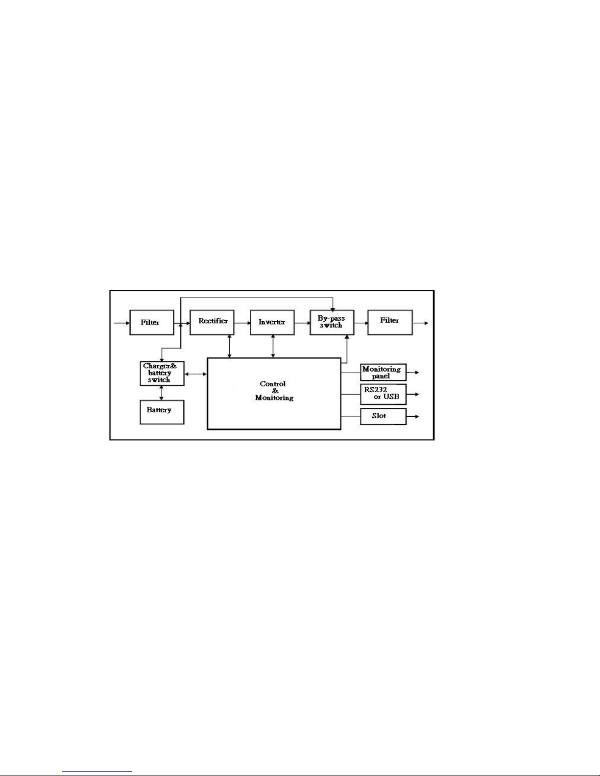
As shown in fig.1 block diagram:
● An input filter reduces transients on the mains
● For maintaining full battery charge, AC-power is rectified and regulated in the rectifier feeding
power to the inverter and battery converter.
● DC power is converted to AC in the inverter passing it on to the load.
● Power is maintained from the battery during a power failure.
● The converter increases voltage appropriately for the inverter.
Fig.1. Block diagram
Efficiency Optimizer function
The Efficiency Optimizer function is a new feature for the UPS adding cost effectiveness,
minimizing power loss and reducing power consumption. Alternating between bypass and on-line
modes is achieved automatically and in accordance with the conditions of the utility power. On-line
mode may be used during times of intermittent power supply, and bypass mode when power flows
smoothly in order to obtain greatest efficiency. Irregularities can be detected in less than a second,
and on-line mode reactivated immediately. Switching back to online mode occurs when input
voltage is outside ±10% or nominal (±15% selectable), when input frequency is outside of ±3Hz or
when no input line is available.
Page 10

10
Although high efficiency is standard, the default operation is in on-line mode. Bypass can be
activated in the LCD panel, though on-line can be run permanently if preferred.
Free Run Mode
The UPS operates in free run mode when input frequency is outside of the selected input frequency
range. Free run mode is when output frequency does not match input frequency. When starting the
UPS, the frequency regulation detected is 50 or 60 Hz ±0.25Hz. Please refer to chapter 7.2 if you
want bypass available while running in free run mode.
Diagnostic tests
When you start the UPS, a diagnostic test is automatically executed that checks electronics, battery,
and reports any problems on the LCD display.
An advanced battery management system always monitors the conditions of the batteries sends any
forewarnings if replacement is needed. Otherwise every 30 days of normal mode operation, a battery
discharge test is performed and any problems reported on the LCD display.
Except during the first 24 hours after startup while the UPS is in charging mode (please see chapter
7.2), diagnostic tests can be performed manually from the front panel at any time.
2.2 System Configuration
The UPS device and the internal backup battery make up the system. Depending on the site and load
requirements of the installation, certain additional options are available as a tailored solution.
Planning a UPS system, the following should be taken into consideration:
● The total demand of the protected system shall dictate the output power rating (VA). Allow a
margin for future expansion or calculation inaccuracies from measuring power requirements.
● Backup time needed will indicate the battery size needed. If load is less than the UPS nominal
power rating then actual backup time is longer.
● The following options are available:
● External Battery Cabinets
● Transformer cabinets
● Maintenance bypass switches
● Connectivity options (relay card, SNMP/WEB card)
Page 11

11
The following UPS models are available
Model
Backup time
Internal batteries
Recharge time to 90% capacity
UPS 1000VA 3~5 min 4 hours
UPS 2000VA 3~5 min 4 hours
UPS 3000VA 3~4 min 4 hours
Additional External Battery Cabinets are available if more back-up time is needed.
Page 12
12
3. Safety Information
Information presented here is vital to all personnel and please also read the UPS safety manual.
Storage and Transportation
Please handle with extreme caution since a high amount of energy is contained with the batteries.
Always keep the unit in position as marked on the packaging and never drop the unit.
Installation
If flammable substances such as gases or fumes are present or if the room is airtight, a safety hazard
situation exists, in which no electrical equipment should be operated.
The instructions in this manual explain how to install the UPS safely. Not acknowledging such
electrical hazards may be fatal, so keep this manual for all future reference.
WARNING!
It is strongly advisable not to open the UPS cabinet as the components have very high
voltage and touching them may be fatal. Only a technician from the manufacturer or an
authorized agent may service the unit. This UPS unit’s output receptacles carry live
voltage even when not connected to a power supply as it has its own energy source.
User’s operations
The only operations that users are permitted to do are:
● Turning the UPS unit on and off
● Operating the users interface
● Connecting data interface cables
● Changing the batteries
All such operations are to be performed exactly as instructed in this manual. The greatest care
possible must be taken for any of these operations and any change thereof may prove very
hazardous to the operator.
Page 13

13
4. Storage
Please adhere to the following instructions if the UPS is not installed immediately:
● Store the equipment as is in its original packing and shipping carton
● Do not store in temperatures outside the range of +15°C to +25°C.
● Ensure that the equipment is fully protected from wet or damp areas and from moist air.
In order to maintain the vitality of the batteries, ensure that the UPS is recharged every 6 months for
at least 8 hours.
5. Installation
5.1 Environment
Ensure that all environmental concerns and requirements are met according to these technical
specifications, otherwise the safety of installation personnel cannot be guaranteed and the unit
may malfunction.
Ensure that you remember the following when locating the UPS system and battery options:
● Avoid extremes of temperature and humidity. Maximal battery life can be attained with a
recommended temperature range of 15 °C to 25 °C.
● Provide protection for the equipment from moisture.
● Space and ventilation requirements must be met. Ensure there is 100mm behind and 50mm on
the sides of the UPS for ventilation.
● Ensure that the front of the UPS remains clear for user operation.
The External Battery Cabinets has to be installed next to the UPS or under the UPS.
Page 14
14
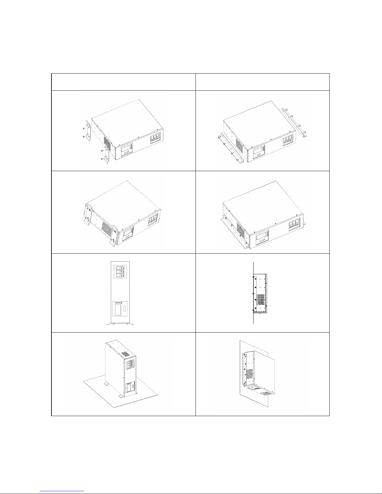
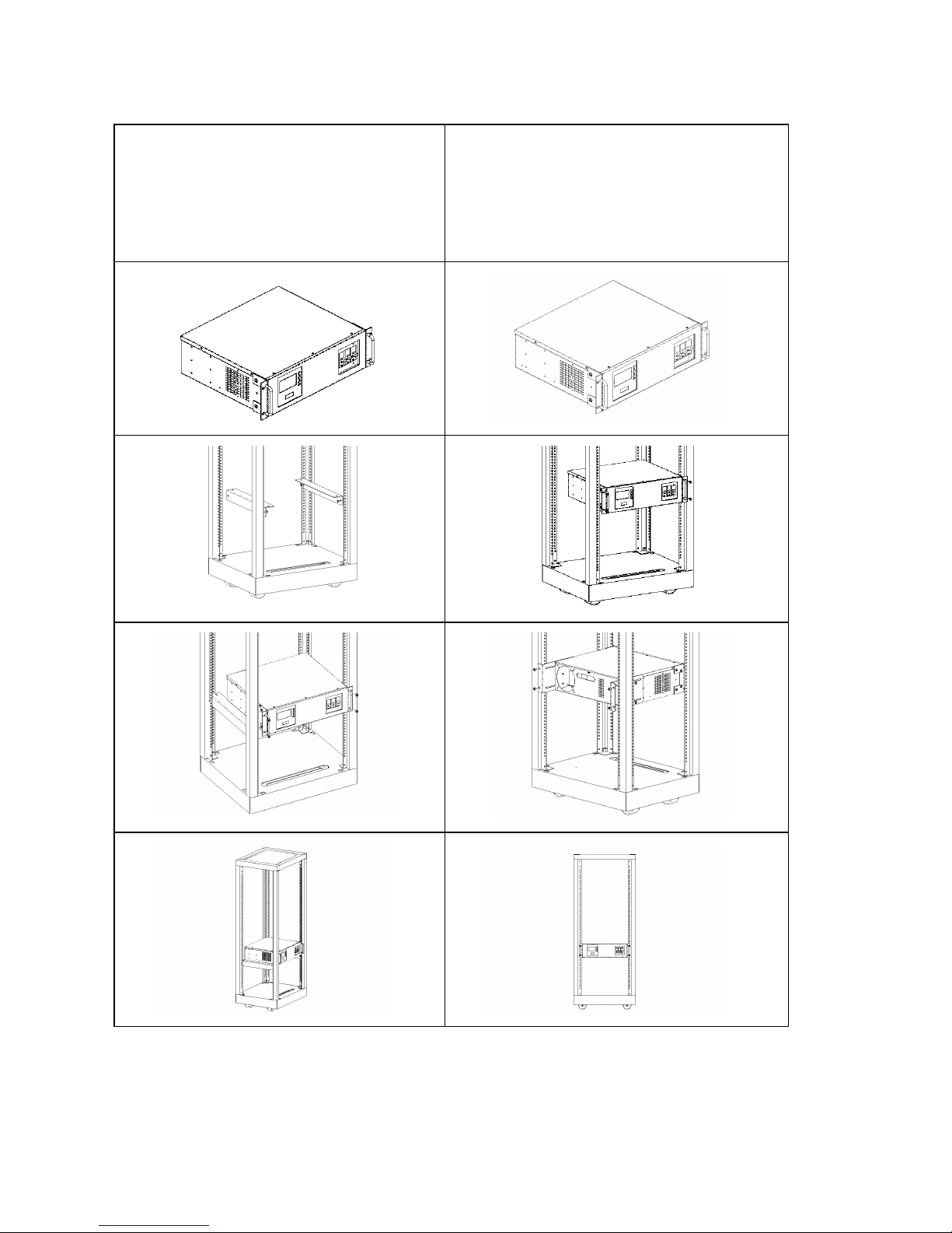
Installation with accessories of “Rack-mounted” types:
Please install the vertical and wall-mounted types of units according to the following
illustration.
V er t i c a l In s t a l l at i o n Wa l l - m o u nt e d i n s t a ll a t i o n .
Installation with accessories of “Rack-mounted” types:
Page 15
15
Please install the types of units according to the following illustration.
Installation with bottom bracket.
Part No: RMB-06, 2 PCS.
Screw: M5*11, 4 PCS.
Installation with rear bracket
Part No: RMB-01, 2PCS.
Screw: M5*11, 4 PCS.
Page 16
16
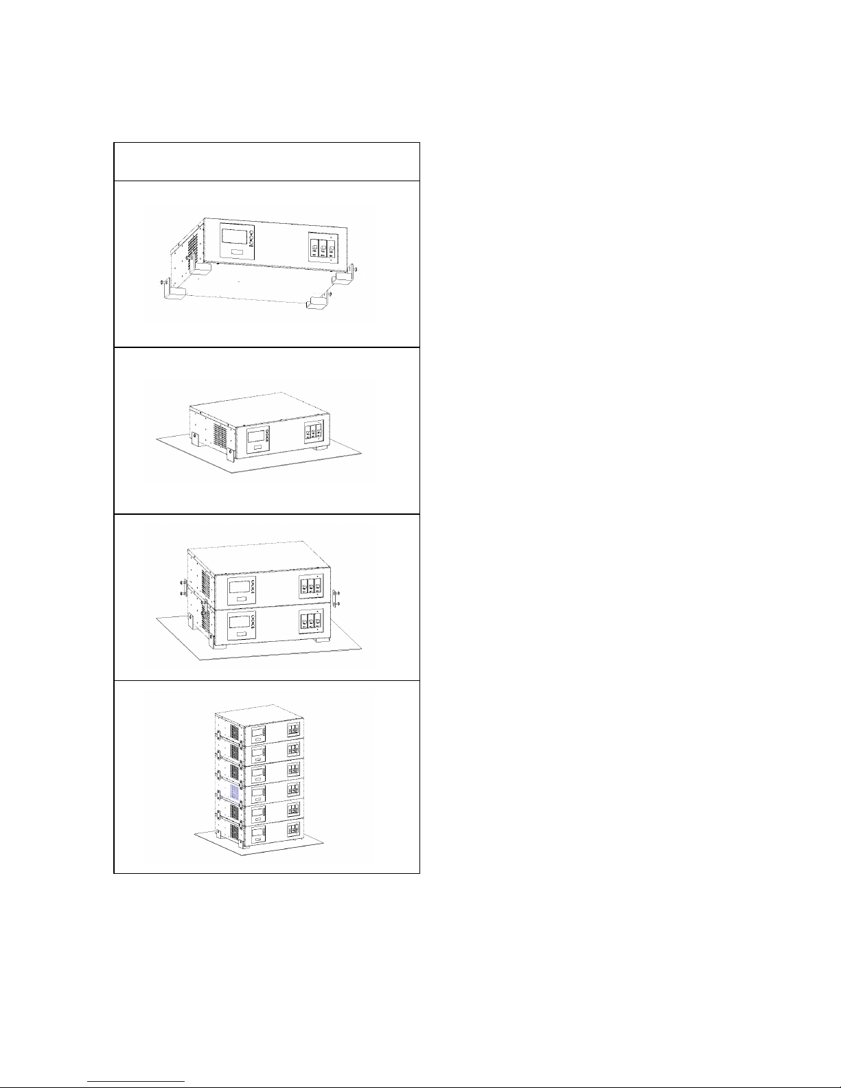
Installation with accessories of “Stack” types:
Please install the types of units according to the following illustration.
St a c k i n st a l l a t i o n
Page 17
17
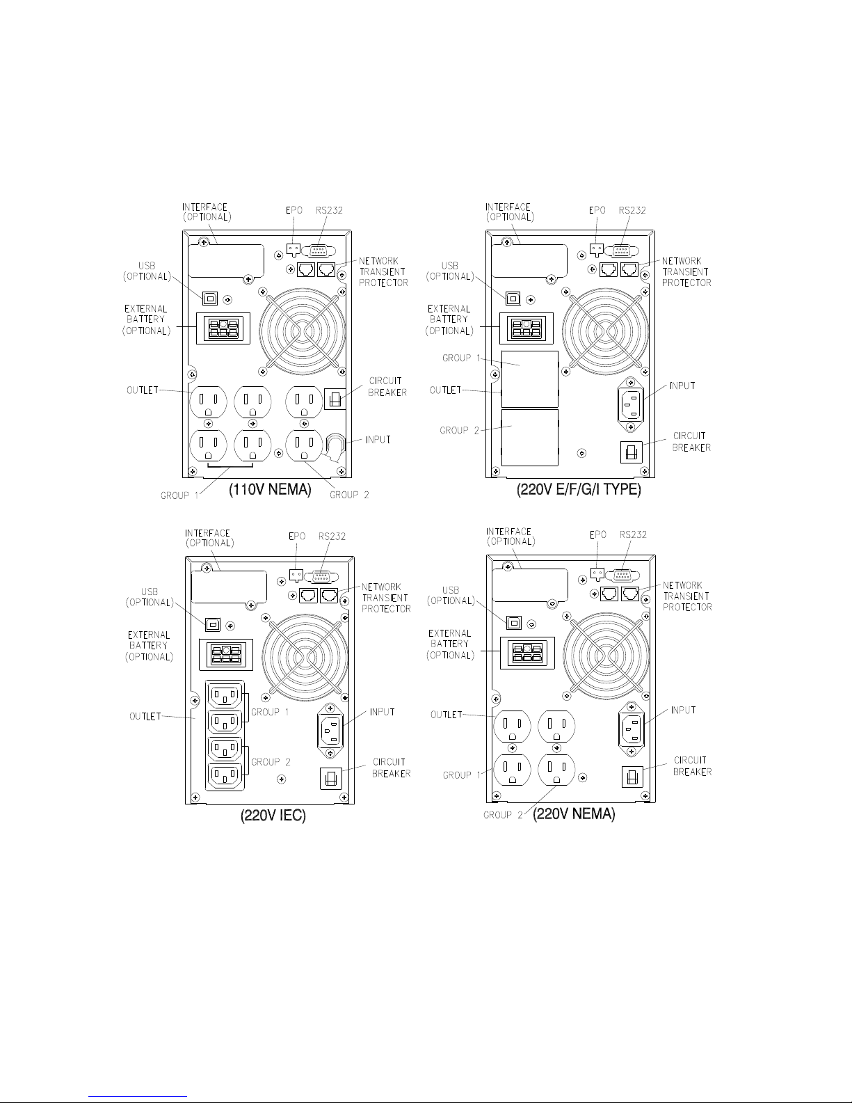
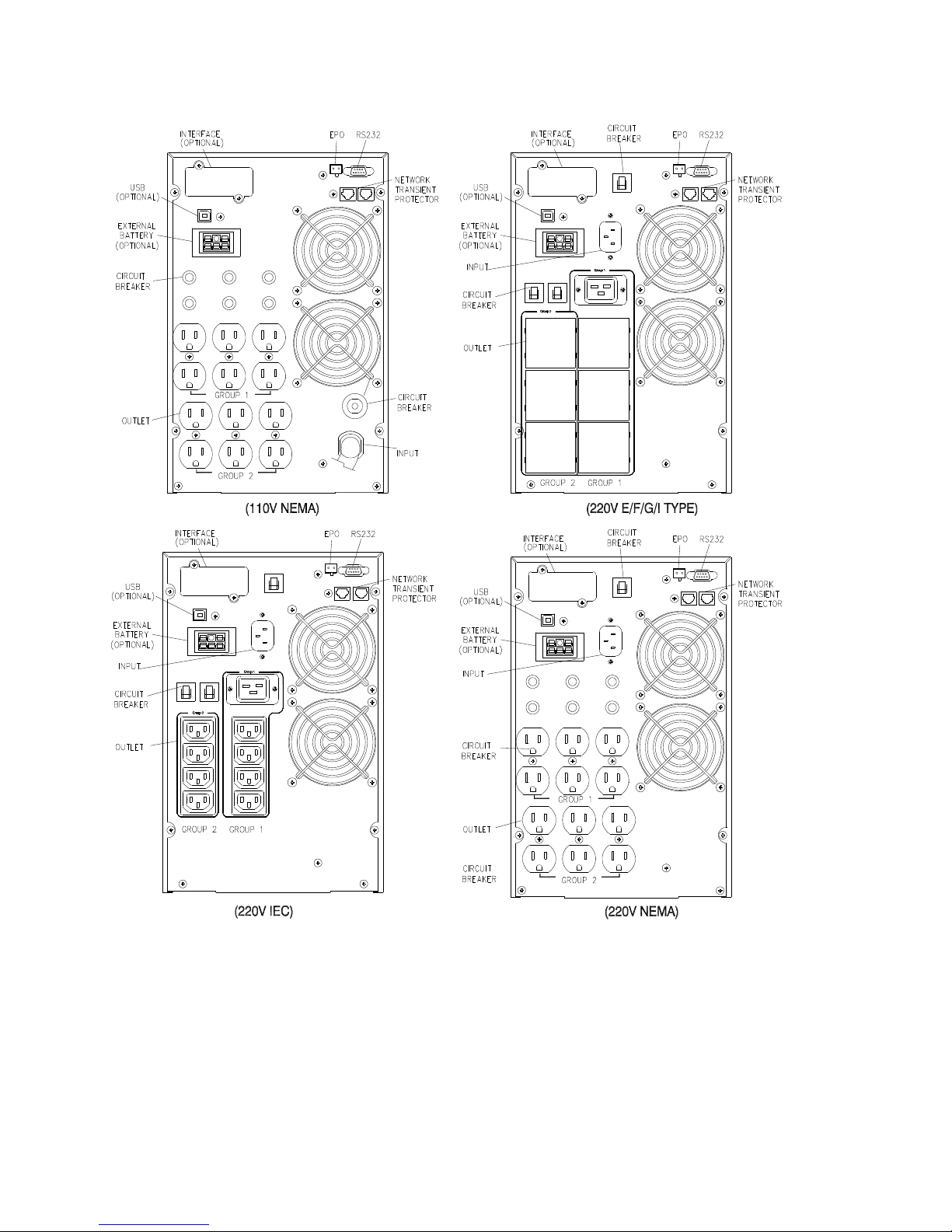
5.2 Rear panel view
1KVA REAR PANEL
Page 18
18
2K~3KVA REAR PANEL
Page 19
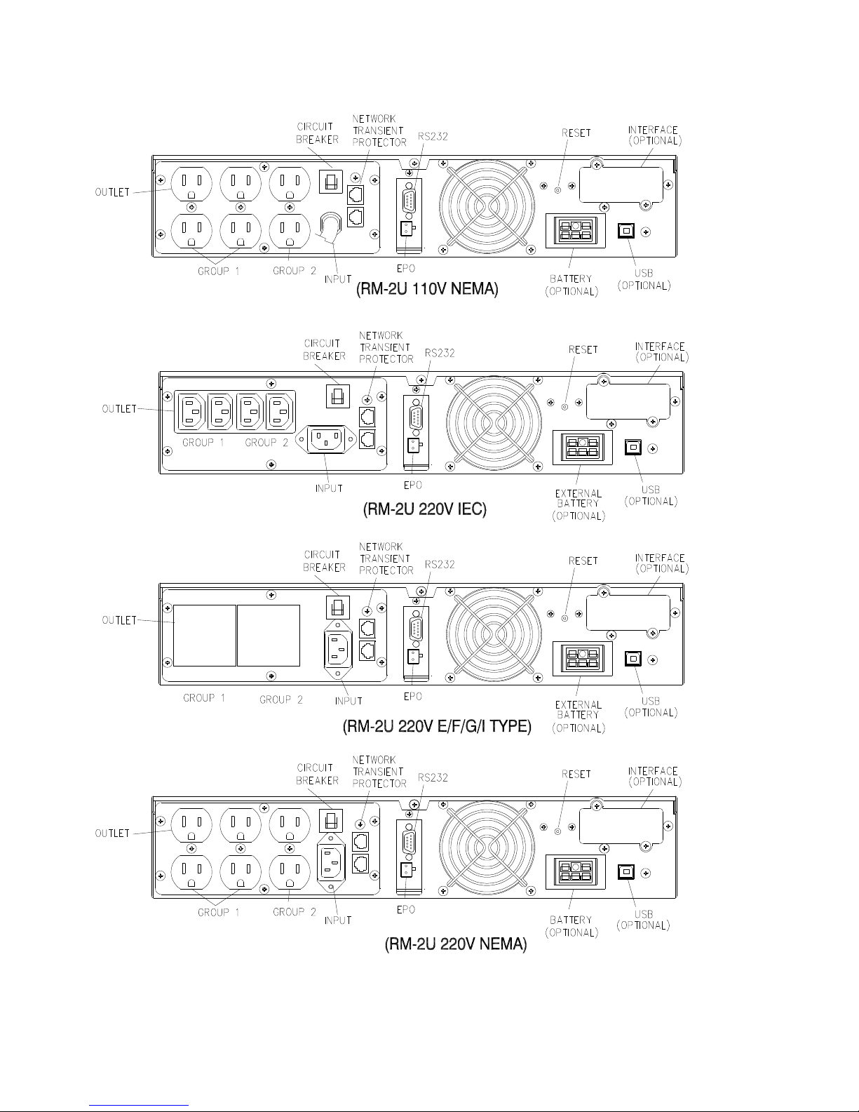
19
RM(2U) 1KVA Rear Panel
Page 20
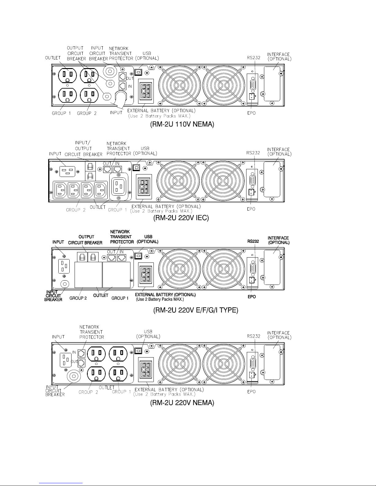
20
RM(2U) 2K-3KVA Rear Panel
Page 21
21
5.3 Connection to mains and loads (1000 - 3000 VA)
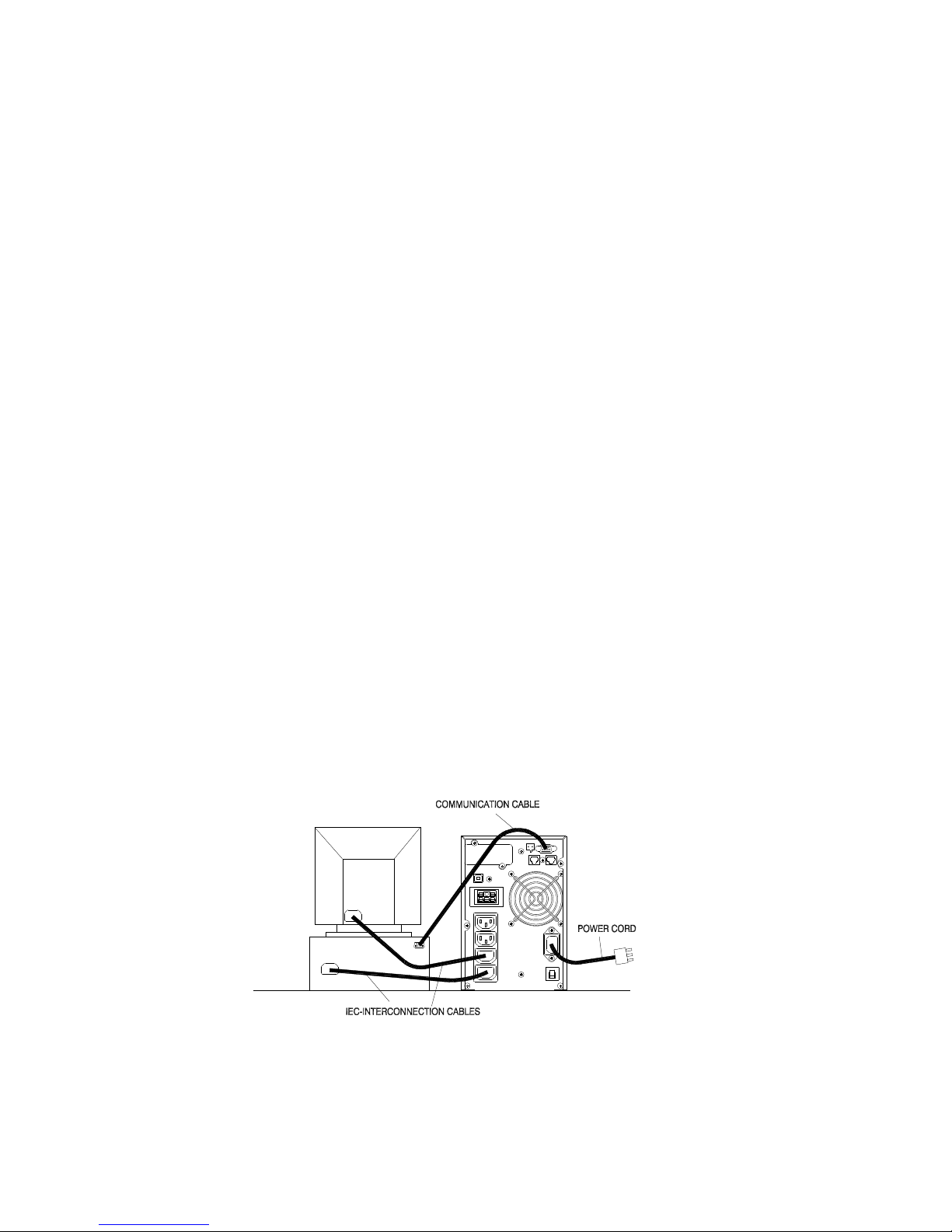
The following Input and Output cables come supplied with all models
1000 VA, (option)- IEC 320 10 A (Input cable)
2000 VA Two IEC-IEC 320 10 A (Load cable)
3000 VA (option)-IEC 320 16 A (Input cable)
Two IEC-IEC 320 10 A (Load cable)
Ensure that the UPS is disconnected from mains and loads while connecting the External
Battery Cabinets, if needed.
Use the battery cable that comes with the External Battery Cabinet to connect the External
Battery Cabinet to the UPS. Connect a second battery cabinet to the first one with the cable
provided if more than one is to be installed.
Be aware of UPS parameters and changing the Battery pack quantity when using the external
battery cabinets (see chapter 7.2)
Connect the Input cable to the UPS and connect the other end to a grounded outlet. The batteries
will automatically charge when connected to the mains. Please realize that although you may
start using the UPS immediately, maximum back-up time will still not be available, so it is
recommended to charge the batteries for a minimum of 8 hours before use.
If unit instantly shows a “Site Wiring Fault”, rotate the connector (Schuko) (see chapter 7.4).
After charging, connect the loads to the UPS (see the example in fig 3).
Do not connect any devices that have the possibility of overloading the UPS or drawing
half-wave rectified current, such as hair dryers or vacuum cleaners.
Should computer or alarm connections be used, use connections according to chapter 6 of the
manual provided with that option. The connections can be referred to on the rear panel.
The installation is now complete.
Fig. 3 Example of Installation of Plug & Play products
Page 22

22
5.4 Default settings at the factory
On the LCD display you will find several of the UPS parameters to select. Default
settings are as follows:
Settings Selection Factory default
Output Voltage Setting
100/110/115/120/127
Vac
120V (FOR LV series)
208/220/230/240 Vac 230V (FOR HV series)
Input/Bypass Voltage
±10%
+10/-15%
+15/-20%
+10/-15%
Input/Frequency
±2%
±5%
±7%
±5%
HE Mode Setting On/Off Off
Free Run Mode On/Off On
Bypass Enable/Disable at free run mode Disable/Enable Disable
Alarm silence On/Off Off
Site wiring alarm Enable/Disable Disable
External Battery pack setting 0, 1, 2 0
You may change default settings, but we recommend that this is done after installation and before
starting up loads. Read UPS configurations in chapter 7.2 for more information.
Page 23
23
6. Computer and Alarm connections
At the back of the UPS is an interface allowing direct communication with your computer system,
the location of which can be found in figure 2. There is a RS232 serial data interface, one USB data
interface and an emergency power off switch supplied. However, the RS232 port cannot be used
when the USB interface is in use.
In addition there is an optional interface slot that allows you to install different communications
cards. It can be used parallel with either the RS232 or USB ports.
Currently there are two cards available for the optional interface slot. An SNMP/WEB card allows
management and monitoring over a network or internet, and the AS/400 card allows voltage free
relay contacts. Your local dealer will have more information about these option cards.
Connecting the UPS to a Computer
The communication device for the UPS and PC comes as a complete package with power
management software. Only the communication cable provided with UPS may be used to connect to
your computer, which is accomplished through the UPS RS232 port. Also ensure that the operating
system on your computer is supported. Instructions provided in the power management software
will help with this installation.
Other advanced power protection solutions such as SNMP are provided by your dealer.
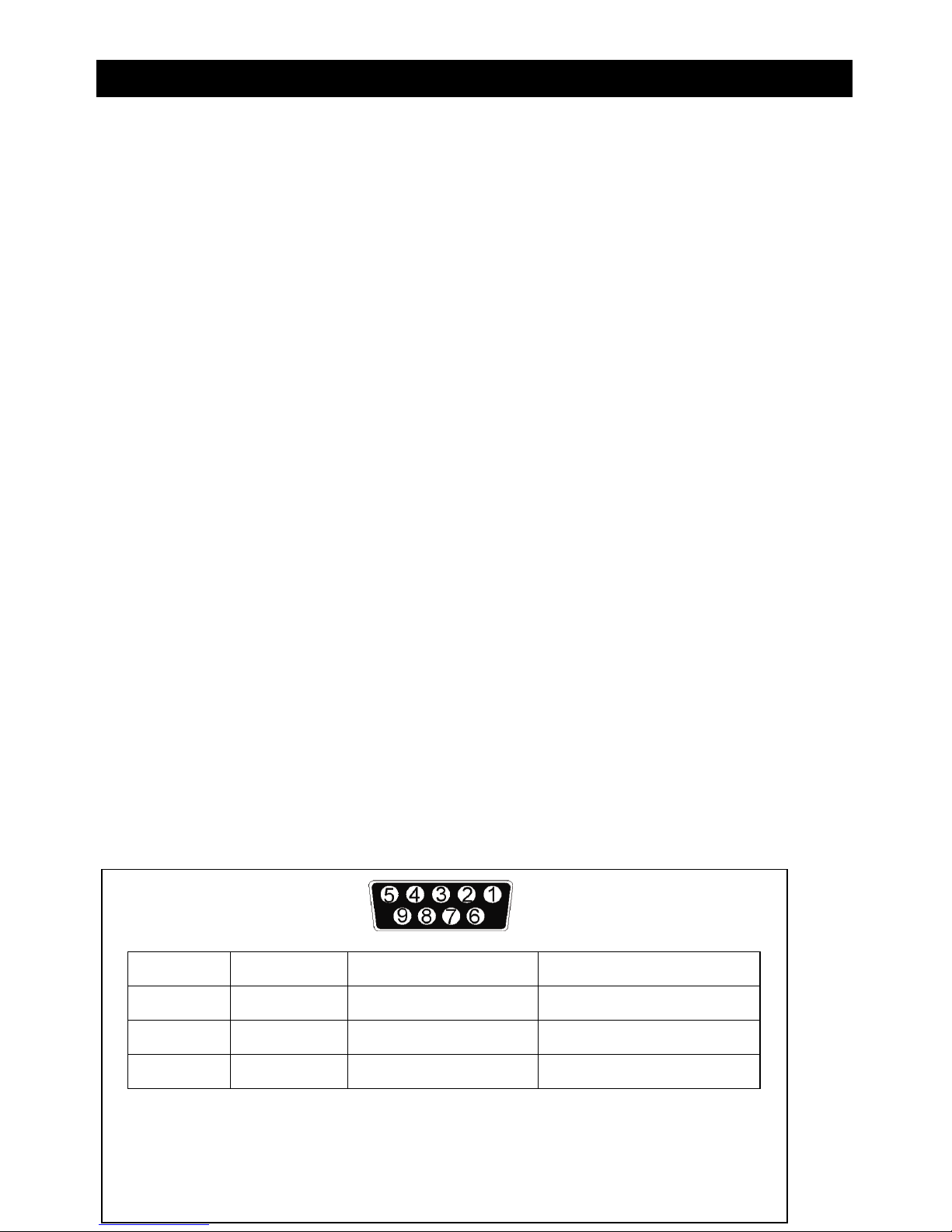
RS-232 Standard Interface port
The RS-232 interface uses a 9-pin female D-sub connector. This information consists of data about
utility, load and the UPS. The interface port pins and their functions are identified in the following
table.
Pin # Signal name Direction (re UPS) Functions
2 TxD Output TxD Output
3 RxD Input RxD / Inverter Off Input
5 Common Common
Page 24

24
6 Output Ac Fail Output
8 Output Low Battery Output
9
Output 12 VDC Power
Caution! Max rated valu
es 12Vdc
Page 25

25
USB port (option)
Connecting the UPS to your computer is accomplished through the USB port on the back of your
computer. USB compliant hardware and operating system will be necessary including installation of
a UPS driver. The serial port cannot be used when using the USB port. The USB cable is standard
and can be bought separately.
6.1 EPO port (emergency power off)
A customer-supplied switch located remotely can be used to open the EPO connection and allows
UPS output receptacles to be switched off. Since the EPO shuts down the equipment immediately,
orderly shutdown procedures are not followed and not by any power management software. The
UPS will have to be manually restarted in order to regain power to the outlets.
Network Transient protector (1000 - 3000 VA)
The network transient protector, located on the back panel, has both IN and OUT jacks, and houses a
single RJ-45 (10BaseT) network connector. Connect the input connector to the jack labeled IN, and
the output connector to the jack labeled OUT.
6.2 Load segments (1000 - 3000 VA)
The power management software controls the sets of receptacles known as load segments which
provides organized shutdown and startup of the equipment. Less critical equipment can be turned off
during power outages saving battery power for critical loads. The power management software
manual has more details regarding this. The load group status can be viewed from the LCD display
and can be changed if necessary. These load segments are usually handled with the UPS
management software. Refer to chapter 5.2 regarding the two load segments that come with each
model.
Page 26

26
7. User’s guide to operations
Necessary information for operation of the unit is covered in this chapter. Normally the
UPS runs automatically, but on those few occasions such as just after installation, all
the starting and shutting down procedures are described herein.
7.1 Starting and shutting down the UPS
Starting the UPS
Ensure that installation was correct and successful and that the input power cable is connected to
a well-grounded outlet.
The UPS can be started by pushing the button on the front panel.
The UPS should now start its inspection of: internal functions, main synchronization and
inverter startup. Then power should start to be supplied via the outlets.
During this inspection, the LCD will display “Ready on”. The LED shall light up when output
power has commenced and the LCD will display “Line mode”.
Switch on the loads.
Shutting down the UPS
Shut down and turn off the loads.
Push the button on the front panel for five seconds. The alarm will sound and the UPS will
shut down.
The LCD will display UPS OFF for a few seconds.
In emergency situations, the EPO located on the back of the unit should be used.
7.2 Button Operation
Please note the three operating buttons on the front panel:
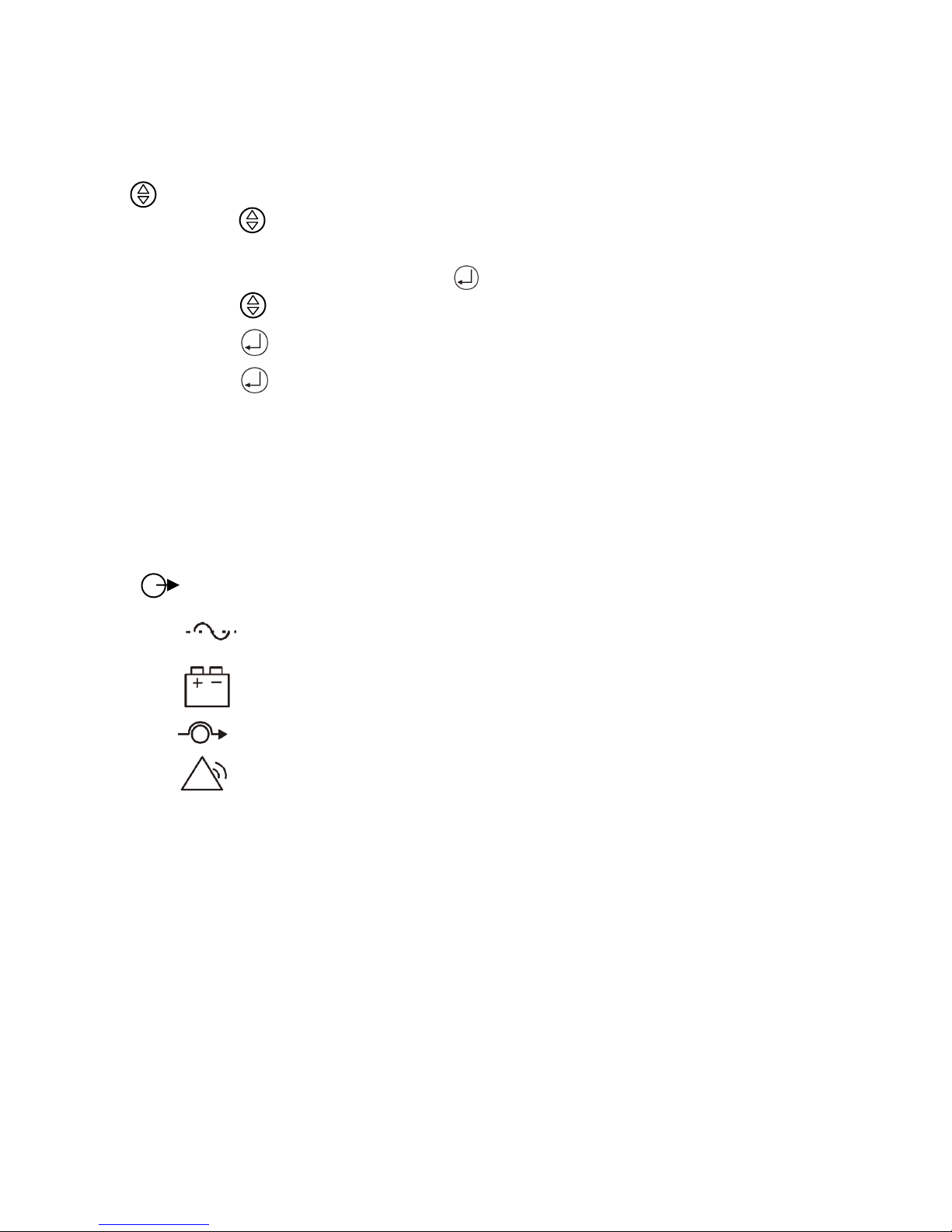
1. “ ” is a ON/ OFF button :
(a). Push the “ ” button (at least 3 seconds) to turn on the UPS.
(b). When UPS is working, push the “ ” button (at least 3 seconds) to turn off the UPS.
2. “ ” is a Enter button. Use this button to check content of UPS and the method is listed
below:
(a). Push the “ ” button (at least 2 seconds) to check content of UPS. Each content can be
Page 27
27
displayed by pressing at once, and it has
fifteen kinds of function to be checked.
(b) If no pressing within 10 seconds, it will return to original status.
3. “ ” is a Function button . Each function can be enabled by pressing this button.
(a). Push the “ ” button (at least 2 seconds) to choose which function that you want.
Each content can be displayed by pressing at once, and it has fourteen kinds of
function to be checked.
(b). After choosing the function, push the “ ” button to enter the function that you want.
(c). Push the “ ” button to choose other function again.
(d). Push the “ ” button to enable your function.
(e). Push the “ ” button to confirm and enable your function.
(f). If no pressing within 10 seconds, it will return to original status.
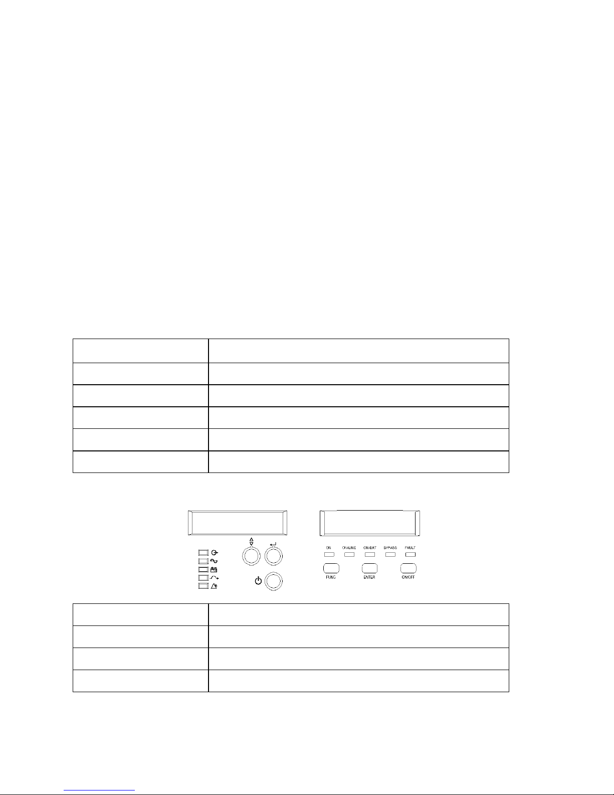
7.3 Control Panel functions
Operation of the UPS is indicated on the monitor panel with five LED indicators and an LCD
screen. This display is also capable of alerting the user with audible alarms.
ON/ This green LED is lit when UPS has been turned on.
ON-LINE/ When the UPS is in normal or static bypass modes, there is voltage at the
output terminals and this LED will light up in green.
ON-BAT/ While operating in battery mode.
BYPASS/ While operating in bypass mode, this LED will light up in yellow.
FAULT/ If any internal error occurs in the UPS, this LED will light up in red and
give off an audible alarm. Press any of the buttons on the front panel to turn off
the alarm.
Page 28
28
Status of the UPS, measurements and alarms are all indicated on the LCD screen.
Figure 6. Control panel
Normal display
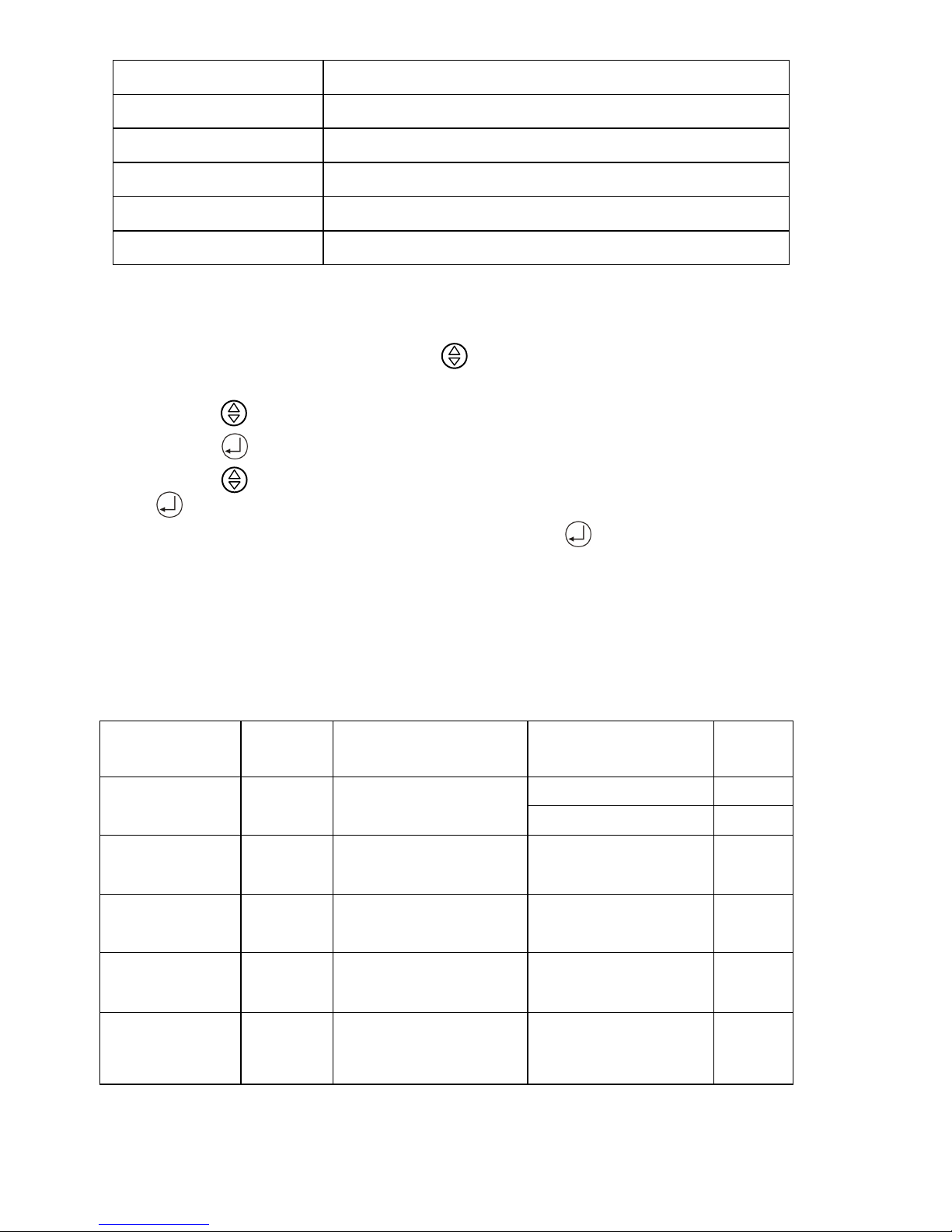
The UPS status is shown in normal display mode. From here you have a choice to go to UPS meters
display and the Setting display by pushing the button.
UPS meters display
Various measurements are available through the UPS meters display; pressing the
button will scroll through the following meters:
LCD message Description
O/P VOLT= xxx, xV Shows Output AC voltage
O/P FREQ= xx, x Hz Shows Output Frequency
I/P VOL T= xxx, xV Shows Input AC voltage
I/P FREQ= xx, x Hz Shows Input Frequency
BAT VOLT= xx,xV Shows Battery Voltage
O/P LOAD%= xx% Shows Load % of max load
O/P W= xW Shows Output Watts
O/P VA= xVA Shows Output VA
O/P CURR= xA Shows Output Current
Page 29
29
BACKUP TIME= xx min Shows Estimated Backup time in minutes
BAT CHARG= xx% Shows approximate percentage of Battery capacity
TEMPERATURE= xxC Shows approximate ambient temperature
BAT PACK NUM= x Shows External Battery Pack Number
RATING = xxxxVA Shows UPS Rating
CPU VERSION xx.x Shows CPU Version
UPS configurations
Various settings that have been chosen are shown in the UPS setting display.
To enter configuration mode, press the button for one second. The first configuration
parameter will be shown on the LCD display.
Press the button to scroll through the parameters.
Press the button to select the parameter.
Press the button to scroll through the options for the selected parameter; Press
the button to select the option.
You may be prompted to save the selection, if so press the button to either confirm or save
your selection. Other options are saved and started automatically. See the table below for further
details.
If no buttons are pressed (or user inactivity) for ten seconds, the UPS shall exit the
configuration mode and return to normal mode displaying Line mode.
Caution!
The factory default settings do not necessarily have to be changed, although you are
free to tailor the UPS to your specific needs.
Settings
LCD
display
Explanation Selection
Factory
default
Output
Volt.Setting
O/P V
Setting
Select Nominal Voltage
208/220/230/240 V 230V
100/110/115/120/127 V 120V
Input/Frequency
I/P F
Setting
Select input frequency
range when UPS goes
into free run mode
±2%
±5%
±7%
±5%
Input/Bypass
Voltage
I/P Bypass
Set
Select Input Voltag
e
range when bypass is
available
±10%
+10/-15%
+15/-20%
+10/-15
%
Free Run Mode
Free Run
Set
Select if UPS can run in
Free run mode
(unsynchronized)
ON/OFF ON
Bypass
Enable/Disable at
Free run mode
Bypass
disable
If Enable is chosen, the
UPS can go to bypass
when unsynchronized.
Disable/Enable Disable
Page 30

30
He mode Setting
HE Mode
Set
Select if UPS runs in
high efficiency mode
ON/OFF OFF
Force Manual
Bypass
Manual
bypass
Permanently force UPS
to bypass. For service
only.**
ON/OFF OFF
Management of
Load groups
Outlet
Setting
You can put the two load
groups on and off form
front panel
1 ON & 2 ON
1 OFF & 2 ON
1OFF & 2 OFF
1 ON & 2 OFF
Both load
segments
ON
Do Battery Test
Battery
Test
Detect battery is normal
or not.
Silence Function Silence Set
Enable or disable silence
function
ON/OFF OFF
Number of
External battery
Packs
Bat
Cabinet
Set
This setting is needed
For UPS to predict
Backup time
0 (only internal
batteries)
1(one external cabinet)
0
Site wiring alarm
Sit Fault
Set
You can enable or
disable the site wiring
Enable /Disable Disable
Select Language Language Select load language
English, German,
French, Spanish,
English
Set Generator
Mode
Generator
Set unit in generator
mode. ***
ON/OFF OFF
Set RS232
communication
RS232
Control
Set RS232
communication enable
or disable
Enable/Disable Enable
Page 31

31
Manual test of the UPS
Manual UPS or Manual Battery tests can be conducted from the UPS configuration as well and are
functional even when the UPS is not charging the battery.
Manual Battery test: Scroll the parameters until Manual Bat test displays on the LCD.
Press the button twice.
**) Note: In order for the UPS and power management software to operate normally, Manual
Bypass should always be set to OFF as the load will not be protected by the unit when Manual
Bypass is ON. This is aimed for operating an external maintenance bypass switch.
***) Note: You should turn UPS off and keep the AC power before you use “Generator” function.
(even you want to select “\Generator\OFF” to back to normal mode).
7.4 Interpreting UPS messages
Troubleshooting procedures described here give simple instructions in determining UPS
malfunctions.
Start the troubleshooting procedure if you witness any alarm indication on the control panel.
Alarm indicators
The UPS gives the following audible alarms:
If UPS is on battery and the ON BATTERY LED is on, UPS will beep every 5 seconds.
If the battery capacity is low and the ON BATTERY LED is flashing, the UPS will beep twice
every 5 seconds.
If UPS is on bypass and the BYPASSED LED is on, UPS will no beep.
If UPS has an internal fault and the ALARM LED is on, the UPS will give a constant audible
alarm displaying the cause on the LCD display.
Silencing an alarm
By pressing any of the three buttons on the front panel, the alarm can be turned off, except when the
battery is low, which will cause the alarm to resound.
On the LCD display, you can also choose silent alarm mode which will not warn you of any
malfunction audibly.
Page 32

32
7.5 Trouble shooting
Displayed on LCD Audible Alarm Alarm Description What You Should Do
Output Overload
Two Beeps per
second
The UPS is overloaded (in
Line Mode). Your
equipment needs more
power than the UPS can
provide. The UPS
operates in bypass.
Shut off the least important
equipment connected to the
UPS. If this solves the overload
problem, the UPS will switch
from bypass back to normal
operation.
Battery Test No Beeps
The UPS is doing a
battery test.
No action needed. The UPS will
return to normal operation when
it successfully completes the
battery test.
Over-Charge Constant beep Batteries are overcharged.
Turn off protected loads. Turn
off UPS and call your local
dealer
Low Battery
2 beeps every
5seconds
The unit is operating on
Battery Power and will
shut down soon due to
very low battery voltage
The unit will restart
Automatically when acceptable
power returns.
On-Battery
Once every 5
seconds
The unit is operating on
Battery Power.
Save your data and perform a
controlled shutdown.
Charger Failure
Constant beep
Cha
rger has failed.
Phone the local dealer
Over-Temperature Constant beep
High ambient
Temperature.
Make sure the unit’s fans and
vent holes are not blocked, and
make sure the ambient
surrounding temperature is not
above 40 degree C. If these
conditions did not solve the
problem, call your service
representative.
Output Short
Constant beep
Output short circuit
Call the Local dealer
High output Voltage
Constant beep
High output voltage
Call the Local dealer
Low Output Voltage
Constant beep
Low output volta
ge Call the Local dealer
Bus Fault
2 Beeps per
second
High internal DC bus
Voltage.
Turn off protected loads. Turn
off UPS and call your local
dealer
Site wiring Fault
1 Beep per
second
Voltage detected Between
Neutral and Ground
UPS mains connector polarity
Wrong. Rotate the connector
(Schuko). UPS installed to
mains supply without ground.
See page 15 on how to disable
the Site wiring alarm
Line abnormal
1 Beep per
second
Wrong AC Line backed
up during auto restart
Page 33
33
8. Maintenance
With a minimal amount of maintenance, you can expect the UPS to application, otherwise consider
changing the batteries. have a long life free of trouble. The most critical issues for the reliability of
the UPS are environmental issues. Ensure that the temperature and humidity are always according to
specifications and keep the area around the unit clean and dust free.
At a temperature of 25°C, the typical battery lifetime is 4 years.
Also check at regular intervals of 6 to 12 months whether the back-up time of the battery is adequate
for its
WARNING!
Batteries may cause electrical shock or burn from high short circuit currents.
Please observe the following precautions: 1. Remove jewelry and metal objects such as
watches and rings. 2. Use tools that have insulated handles. 3. Keep tools and other metal
objects from contacting and away from the batteries.
ELECTRIC ENERGY HAZARD. Do not attempt to rewire, alter, or change any battery
wiring or connectors. Attempting to make such alterations can cause injury.
Replace the batteries with the same number and type as originally installed batteries.
DO NOT DISCONNECT the batteries while UPS is in Battery mode.
Page 34

34
9. Technical Specifications
9.1 .1Power Range 1000-3000 VA at P.F 0.8 (LV) (Tower and 19” RM model)
GENERAL
Rated power 1000 VA, 2000 VA, 3000 VA at P.F 0.8
Technology On-line, double conversion topology with automatic bypass
INPUT
Phase: Single phase with ground
Bypass Voltage 96-138 VAC (user selectable)
Input Voltage range: 60/70/80/90VAC-144 VAC
60V at 25% load, 70V at 50%, 80V at 75%, 90V at 100%
Frequency: 50/60 Hz. Auto selection
Frequency window from mains 45-65 Hz
Synchronization window ± 3Hz.
Input current 1000 VA 8.3A, 2000 VA 16.7A, 3000 VA 25A
Input Power factor: 0.97
OUTPUT
Output Voltage: 100/110/115/120/127 VAC, selectable from LCD panel
Voltage regulation: ± 2%
Voltage distortion: < 5% THD at full non-linear load, < 2% THD at full linear load
Frequency regulation ± 0.25 Hz (battery or free running mode)
Dynamic response: ± 9 % max from 100% to 20 % or from 20% to 100 % linear
load
Overload capacity: 106-120% 30 sec, 121-150% 10 sec
Efficiency: about 89%
9.1.2 Power Range 1000-3000 VA at P.F0.9 (LV) (Tower and 19” RM model)
GENERAL
Rated power 1000 VA, 2000 VA, 3000 VA at P.F0.9
Technology On-line, double conversion topology with automatic bypass
INPUT
Phase: Single phase with ground
Bypass Voltage 96-138 VAC (user selectable)
Input Voltage range: 60/70/80/90VAC-144 VAC
60V at 25% load, 70V at 50%, 80V at 75%, 90V at 100%
Frequency: 50/60 Hz. Auto selection
Page 35

35
Frequency window from mains 45-65 Hz
Synchronization window ± 3Hz.
Input current 1000 VA 8.3A, 2000 VA 16.7A, 3000 VA 25A
Input Power factor: 0.97
OUTPUT
Output Voltage: 100/110/115/120/127 VAC, selectable from LCD panel
Voltage regulation: ± 2%
Voltage distortion: < 5% THD at full non-linear load, <
2% THD at full linear load
Frequency regulation ± 0.25 Hz (battery or free running mode)
Dynamic response: ± 9 % max from 100% to 20 % or from 20% to 100 % linear
load
Overload capacity: 106-120% 30 sec, 121-150% 10 sec
Efficiency: about 89%
WARNING:
"When power supplied by external batteries, output toward loads must be
limited to less than 90% of overall power generation."
9.2.1 Power Range 1000-3000 VA at P.F 0.8(HV)
(Tower and 19” RM model)
GENERAL
Rated power 1000 VA, 2000 VA, 3000 VA at P.F 0.8
Technology On-line, double conversion topology with automatic bypass
INPUT
Phase Single phase with ground
Bypass Voltage: 184-265 VAC (user selectable)
Input Voltage range: 120/140/160/180 VAC-276 VAC
120V at 25% load, 140V at 50%, 160V at 75%, 180V at 100%
Frequency: 50/60 Hz. Auto selection
Frequency window from mains 45-65 Hz
Synchronization window ± 2.5Hz.
Input current 1000 VA 4.3A, 2000 VA 8.7A, 3000 VA 13A
Input Power factor: 0.97
OUTPUT
Output Voltage: 208/220/230/240 VAC, selectable from LCD panel
Voltage regulation: ± 2%
Page 36

36
Voltage distortion: < 5% THD at full non-linear load, <
2% THD at full linear load
Frequency regulation ± 0.25 Hz (battery or free running mode)
Dynamic response: ± 9 % max from 100% to 20 % or from 20% to 100 % linear
load
Overload capacity: 106-120% 30 sec, 121-150% 10 sec
Efficiency: about 89%
9.2.2 Power Range 1000-3000 VA at P.F 0.9(HV)
(Tower and 19” RM model)
GENERAL
Rated power 1000 VA, 2000 VA, 3000 VA at P.F0.9
Technology On-line, double conversion topology with automatic bypass
INPUT
Phase Single phase with ground
Bypass Voltage: 184-265 VAC (user selectable)
Input Voltage range: 120/140/160/180 VAC-276 VAC
120V at 25% load, 140V at 50%, 160V at 75%, 180V at 100%
Frequency: 50/60 Hz. Auto selection
Frequency window from mains 45-65 Hz
Synchronization window ± 2.5Hz.
Input current 1000 VA 4.3A, 2000 VA 8.7A, 3000 VA 13A
Input Power factor: 0.97
OUTPUT
Output Voltage: 208/220/230/240 VAC, selectable from LCD panel
Voltage regulation: ± 2%
Voltage distortion: < 5% THD at full non-linear load, < 2% THD at full linear load
Frequency regulation ± 0.25 Hz (battery or free running mode)
Dynamic response: ± 9 % max from 100% to 20 % or from 20% to 100 % linear
load
Overload capacity: 106-120% 30 sec, 121-150% 10 sec
Efficiency: about 89%
WARNING:
"When power supplied by external batteries, output toward loads must be
limited to less than 90% of overall power generation."
Page 37

37
ENVIRONMENTAL
Ambient temperature: +0 °C to +40 °C
Recommended temperature: +15 °C to +25 °C
Storage temperature: -15 °C to +50 °C
Cooling: Forced air-cooling
Humidity: 0-95%, non-condensing
Audible noise: < 45 db normal and battery mode (1000 VA)
< 50 db normal and battery mode (2000-3000 VA)
STANDARDS
Safety: EN50091-1, EN62040-1-1, IEC62040-1-1, UL1778
Emissions: EN50091-2, EN62040-2 / IEC62040-2
Immunity: EN50091-2, FCC Class B (1000VA)
EN50091-2, FCC Class A (2000/3000VA)
EN62040-2 Category C1 (1000VA)
EN62040-2 Category C2 (2000/3000VA)
HV Tower Model at P.F 0.8
OUTPUT POWER 1000VA/800W 2000VA/1600W 3000VA/2400W
Connection Input IEC 320 (10A) IEC 320 (10A) IEC 320 (16A)
Connection Output
4 x IEC 320 (10A)
8 x IEC 320 (10A),
1 x IEC 320 (16A)
8 x IEC 320 (10A),
1 x IEC 320 (16A)
4 x 5-15R (US) 12 x 5-15R (US) 12 x 5-15R (US)
2 x Europe
6 x Europe,
1 x IEC 320 (16A)
6 x Europe,
1 x IEC 320 (16A)
Battery type Lead-acid 7AH/12V Lead-acid 7AH/12V Lead-acid 7AH/12V
Number of batteries 3 6 8
Backup time/
full load
3~5 min 3~5 min 3~4 min
Recharge time <4 hours to 90% <4 hours to 90% <4 hours to 90%
Dimensions
W x D x H mm
152 x 420 x 238 225 x 420 x 358 225 x 420 x 358
Net Weight kg 16.2 31.1 33.6
Page 38

38
HV Tower Model at P.F 0.9
OUTPUT POWER 1000VA/900W 2000VA/1800W 3000VA/2700W
Connection Input IEC 320 (10A) IEC 320 (10A) IEC 320 (16A)
Connection Output
4 x IEC 320 (10A)
8 x IEC 320 (10A),
1 x IEC 320 (16A)
8 x IEC 320 (10A),
1 x IEC 320 (16A)
4 x 5-15R (US) 12 x 5-15R (US) 12 x 5-15R (US)
2 x Europe
6 x Europe,
1 x IEC 320 (16A)
6 x Europe,
1 x IEC 320 (16A)
Battery type Lead-acid 7AH/12V Lead-acid 7AH/12V Lead-acid 7AH/12V
Number of batteries 3 6 8
Backup time/
full load
3~5 min 3~5 min 3~4 min
Recharge time <4 hours to 90% <4 hours to 90% <4 hours to 90%
Dimensions
W x D x H mm
152 x 420 x 238 225 x 420 x 358 225 x 420 x 358
Net Weight kg 16.2 31.1 33.6
HV 19” Rack-mount Model at P.F 0.8(2U)
OUTPUT POWER
1000VA/800W 2000VA/1600W 3000VA/2400W
Connection Input IEC 320 (10A) IEC 320 (10A) IEC 320 (16A)
Connection Output
4 x IEC 320 (10A)
4 x IEC 320 (10A),
1 x IEC 320 (16A)
4 x IEC 320 (10A),
1 x IEC 320 (16A)
4 x 5-15R (US) 4 x 5-15R (US) 4 x 5-15R (US)
2 x Europe 2 x Europe 2 x Europe
Battery type Lead-acid 7AH/12V Lead-acid 7AH/12V Lead-acid 5AH/12V
Number of batteries
3 6 8
Backup time/
full load
3~5 min 3~5 min 3~4 min
Recharge time <4 hours to 90% <4 hours to 90% <4 hours to 90%
Dimensions
W x D x H mm
428 x 425 x 84 428 x 635 x 84 428 x 635 x 84
Net Weight kg 17.1 31.6 32.5
Page 39

39
HV 19” Rack-mount Model at P.F 0.9(2U)
OUTPUT POWER
1000VA/900W 2000VA/1800W 3000VA/2700W
Connection Input IEC 320 (10A) IEC 320 (10A) IEC 320 (16A)
Connection Output
4 x IEC 320 (10A)
4 x IEC 320 (10A),
1 x IEC 320 (16A)
4 x IEC 320 (10A),
1 x IEC 320 (16A)
4 x 5-15R (US) 4 x 5-15R (US) 4 x 5-15R (US)
2 x Europe 2 x Europe 2 x Europe
Battery type Lead-acid 7AH/12V Lead-acid 7AH/12V Lead-acid 5AH/12V
Number of batteries
3 6 8
Backup time/full
load
3~5 min 3~5 min 2.5~3.5 min
Recharge time <4 hours to 90% <4 hours to 90% <4 hours to 90%
Dimensions
W x D x H mm
428 x 425 x 84 428 x 635 x 84 428 x 635 x 84
Net Weight kg 17.1 31.6 32.5
LV Tower Model ay P.F 0.8
OUTPUT POWER 1000VA/800W 2000VA/1600W 3000VA/2400W
Connection Input Attached power cord
Connection Output 6 x 5-15R (US) 12 x 5-15R (US) 12 x 5-15R (US)
Battery type Lead-acid 7AH/12V Lead-acid 7AH/12V Lead-acid 7AH/12V
Number of batteries 3 6 8
Backup time/
full load
3~5 min 3~5 min 3~4 min
Recharge time <4 hours to 90% <4 hours to 90% <4 hours to 90%
Dimensions
W x D x H mm
152 x 420 x 238 225 x 420 x 358 225 x 420 x 358
Net Weight kg 16.2 31.1 33.6
Page 40

40
LV Tower Model ay P.F 0.9
OUTPUT POWER 1000VA/900W 2000VA/1800W 3000VA/2700W
Connection Input Attached power cord
Connection Output 6 x 5-15R (US) 12 x 5-15R (US) 12 x 5-15R (US)
Battery type Lead-acid 7AH/12V Lead-acid 7AH/12V Lead-acid 7AH/12V
Number of batteries 3 6 8
Backup time/
full load
3~5 min 3~5 min 3~4 min
Recharge time <4 hours to 90% <4 hours to 90% <4 hours to 90%
Dimensions
W x D x H mm
152 x 420 x 238 225 x 420 x 358 225 x 420 x 358
Net Weight kg 16.2 31.1 33.6
LV 19” Rack-mount Model at P.F 0.8(2U)
OUTPUT POWER
1000VA/800W 2000VA/1600W 3000VA/2400W
Connection Input Attached power cord
Connection Output 6 x 5-15R (US) 4 x 5-15R (US) 4 x 5-15R (US)
Battery type Lead-acid 7AH/12V Lead-acid 7AH/12V Lead-acid 5AH/12V
Number of batteries
3 6 8
Backup time/
full load
3~5 min 3~5 min 3~4 min
Recharge time <4 hours to 90% <4 hours to 90% <4 hours to 90%
Dimensions
W x D x H mm
428 x 425 x 84 428 x 635 x 84 428 x 635 x 84
Net Weight kg 17.1 31.6 32.5
Page 41

41
LV 19” Rack-mount Model at P.F 0.9(2U)
OUTPUT POWER
1000VA/900W 2000VA/1800W 3000VA/2700W
Connection Input Attached power cord
Connection Output 6 x 5-15R (US) 4 x 5-15R (US) 4 x 5-15R (US)
Battery type Lead-acid 7AH/12V Lead-acid 7AH/12V Lead-acid 5AH/12V
Number of batteries
3 6 8
Backup time/
full load
3~5 min 3~5 min 2.5~3.5 min
Recharge time <4 hours to 90% <4 hours to 90% <4 hours to 90%
Dimensions
W x D x H mm
428 x 425 x 84 428 x 635 x 84 428 x 635 x 84
Net Weight kg 17.1 31.6 32.5
Battery Cabinets
1000 VA 2000 VA 3000 VA
Battery type
Lead-acid
7 AH/12 V
Lead-acid
7 AH/12 V
Lead-acid
5 AH/12 V
Number of batteries 6 12 16
Backup time/
full load
Approx. 13~15 min
(battery pack only)
Approx. 13~15 min
(battery pack only)
Approx. 10~13 min
(battery pack only)
Recharge time <8 h to 90% <8 h to 90% <8 h to 90%
Dimensio
ns W x D
x H mm
Tower 152 x 420 x 238 225 x 420 x 358 225 x 420 x 358
RM2U 428 x 425 x 84 428 x 500 x 84 428 x 500 x 84
Net
Weight
Kg
Tower 20 42 45.2
RM2U 21 43.5 46.7
Page 42
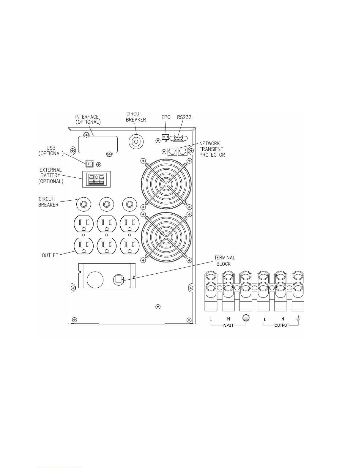
42
Terminal Block (optional)
Please refer to the terminal block connection diagram to connect and use No. 10 AWG, 90°C copper
wire and 20 lb-in torque force when connecting.
CAUTION : To reduce the risk of fire, connect only to a circuit provided with 30 amperes
maximum branch circuit overcurrent protection in accordance with the National Electrical Code,
ANSI/NFPA 70.
Page 43

43
10. Manual Bypass Operation
(Switching from ONLINE to BYPASS)
*Used only when External Manual Bypass switch is installed.
UPS configurations
1. Various settings that have been chosen are shown in the UPS setting display.
2. To enter configuration mode, press the button for one second. The first configuration
parameter (Output Volt Setting) will be shown on the LCD display.
3. Press the button to scroll through the parameters and stop at parameter (Manual
Bypass)
4. Press the button to select the parameter (Manual Bypass).
5. You will see factory default (Off).
6. Press the button to scroll through the options for Manual Bypass till you see option
(On).
7. Press the button to select the option (On).
8. You may be prompted to save the selection, if so press the button to either confirm
or save your selection. Other options are saved and started automatically. See the table
below for further details.
9. If no buttons are pressed (or user inactivity) for ten seconds, the UPS shall exit the
configuration mode and return to normal mode displaying Line mode.
10. After switching to Manual Bypass, you will see Manual Bypass on the LCD display.
11. After verifying the UPS in on Manual Bypass, switch the external manual bypass switch
to BYPASS mode.
12. After switching the external manual bypass switch to BYPASS mode, you will see the red
light on the external bypass box. The UPS is now on BYPASS mode.
Caution!
The factory default settings do not necessarily have to be changed, although you are free to tailor the
UPS to your specific needs.
Page 44

44
Manual Bypass Operation
(Switching from BYPASS to ONLINE)
*Used only when External Manual Bypass switch is installed.
UPS configurations
1. Verify the UPS is in Manual Bypass Mode.
2. Confirm that UPS is in Manual Bypass Mode, proceed to switch the External Manual Bypass
Switch to UPS mode. Verify the red light is off
3. To enter configuration mode, press the button for one second. The first configuration
parameter (Output Volt Setting) will be shown on the LCD display.
4. Press the button till you see parameter (Manual Bypass).
5. Press the button to select the parameter.
6. You will see Manual Bypass is (On).
7. Press the button to scroll through the options for Manual Bypass till you see option (Off).
8. Press the button to select the option (Off).
You may be prompted to save the selection, if so press the button to either confirm or save
your selection. Other options are saved and started automatically. See the table below for further
details.
9. If no buttons are pressed (or user inactivity) for ten seconds, the UPS shall exit the
configuration mode and return to normal mode displaying Line mode.
10. After switching to Online mode, you will see Online on the LCD display. The UPS is now on
ONLINE mode.
Caution!
The factory default settings do not necessarily have to be changed, although you are free to tailor the
UPS to your specific needs.
 Loading...