


PLL
Copyright 2008, Karsect Incorporated
KP1R/KP1TA
Professional Wireless Monitor System
www.karsect com.
Agent:
Thank you for purchasing this product, please read this instruction
carefully so that can understand how to operate the product of style
you bought correctly. Please store this instruction in a safe place
after reading as a reference in the furture.
USER MANUAL
Specifications:
KP1TA Transmitter
Frequency Range
Bandwidth
Oscillation Mode
Frequency Stability
Modulation
Output Power
Spurious Rejection
Max. Deviation Range
Frequency Response
T.H.D.
Audio Output
Audio Input
Headphone Output
Headphone Output Impedance
Antenna Connector
Dimensions
KP1R Receiver
Frequency Range
Bandwidth
Oscillation Mode
Frequency Stability
Modulation Mode
Max. Deviation Range
Receiving Mode
Receiving Sensitivity
Squelch Level
T.H.D.
Max. S/N Ratio
Frequency Response
Stereo Separation
Output Jack
Output Power(32 )
Headphone Impedance
Power Supply
Current Consumption
Dimensions
903-926.5MHz
902-928
PLL Synthesized
0.005% 0 ~+50
FM stereo modulation
8FSK
Low: <10mW; High: <100mW
50~15,000Hz
<0.5% (At maximum deviation range at 1KHz)
Line leve X2, XLR
6.3mm phone jack X2
6.3mm stereo phone jack with adjustable volume
TNC
TNT (50 impedance)
205X160X45mm
903-926.5MHz
902-928
PLL Synthesized
0.005% 0 ~+50
FM stereo modulation
Diversity receiving
-100dBm -90dBm -70dBm
80-15,000Hz, 3dB
3.5mm stereo headphone jack
2X50mW under 1KHz (T.H.D. 3%)
2AA batteries
123X65X27mm
12
MHz
25MHz
-60dBc
25KHz
16
MHz
25MHz
68KHz
-107dBm
1%
94dBA
35dB
16
150mA
TABLE OF CONTENTS
1.System Features
2.Quick Set-up and Use Guide
3.Performance Guide
4.KP1TA Transmitter
Controls and Features
Transmitter Setting
System Configuration and Application
Transmitter Function
5.KP1R Receiver
Controls and Features
Receiver Controls
Receiver Setting
Battery Installation for Receiver
Receiver Function
Headphone
6.Mix Mode/Stereo Control
7.Mix Mode Application
8.Rack Mounting For Receivers
9.Specification
System Features
KP1TA Transmitter Features
1. UHF-band PLL Synthesized design.
2. Frequency agility over a 23.5MHz
bandwidth, with 48 pre-programmed
frequencies available.
3. Bu ilt -in li mi t er ci rcui try elimina tes
distort ion un d er ex cess ive input
levels.
4. Fron t pan e l monitor ing headphone
jack.
KP1R Receiver Features
1. UHF-band PLL Synthesized design.
2. Frequenc y agili ty ov e r a 2 5 M Hz
Bandwidth , with 4 8
Frequenc ie s available with the touch
of a singl e button.
3. Dual-antenna true diversity reception
Eliminating sig n al dr o po u t an d
enhancing RF stability.
4. POWER on/off and R F signal indicators.
Pre-programmed
)&&:$51,1*
&KDQJHVRUPRGLILFDWLRQVQRWH[SUHVVO\DSSURYHGE\WKH
SDUW\UHVSRQVLEOHIRUFRPSOLDQFHFRXOGYRLG\RXU
DXWKRULW\WRRSHUDWHWKHHTXLSPHQW
1
1
2
2
3
3
4
4
5
6
6
7
7
8
8
8
9
10
11
12
Quick Set-Up and Use Guide
KP1TA transmitter
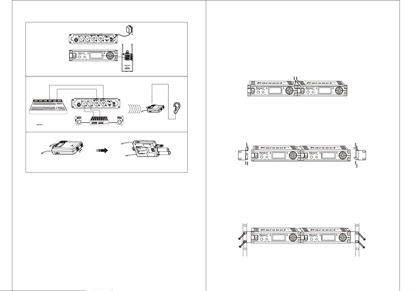
RACK MOUNTING DUAL RECEIVER
1.Align the receivers side by side so that front panels both face the direction
2.Place the supplied straddle bars in the recesses on the top and bottom of
the receivers.
So the barsoverlap both receivesrs.
CAUTION:DO not over-tighten the screws.
Turn ON the system and set to
same frequency and channel
1R
KP
Press the battery compartment door
follow the direction instruction to open
KP1TA transmitter
Install the batteries follow the battery direction
instruction which shown on the case of receiver
KP1R
KP1R receiver
1R
KP
KP1R receiver
Performance Guide
Aim at the characteristic of ear, to care and prevent your ear and equipment, the
normal sound pressure level of headphone is 90dB in a colsing circumstance.
Hereinafter, the divisiory datum for user reference---on maximum time exposure
to sound pressure levels before hearing damage occurs.
3.position the rack-mount brackets over the holes into the sides of each receiver.
4.Secure the brackets to the receivers with the supplied screws
5.Slide the linked receivers into a 19-inch audio equipment rack.
6.Secure the brackets to the rack using the supplied screws.
90 dB SPL at 8 Hours
95 dB SPL at 4 Hours
100 dB SPL at 2 Hours
105 dB SPL at 1 Hours
110 dB SPL at 30 Minutes
115 dB SPL at 15 Minutes
120 dB SPL -----Damage may occur
2
11

4. Mix Mode Application
Counterclockwise Mid-Point Clockwise
1. Receiver receives
two signals from
the transmitter
Channel 1
3. The receiver sends the
mixed signal to both
headphones.
Channel 2
2. Using the balance knob,
the user blends the two
signals until the correct
mix is achieved.
4. The user may continue
KP1R
to adjust the blend using
the balance knob
throughout the performance.
1. KP1TA Transmitter
1.1 Controls and Features
Front panel
2
Rear panel
1. Power Switch: Turns transmitter power ON/OFF.
2. Headphone Output Jack: Connects the headphone.
3. Headphone Volume Control: Adjust the volume of headphone.
4. Indicator of Volume Limiter: To indicate whether the limiter function works.
5. LCD: Display the working informations of transmitter.
SYSTEM COMPONENTS
1.Receiver.....................................................................
2.Transmitter ................................................................
3.Headphone ................................................................
4.Audio cable ................................................................
5.AC power adapter for receiver....................................
6.19-inch equipment rack installation kit........................
7.Battery 1.5V................................................................
8.User guide..................................................................
10
a. Level indicator of audio left/channel 1
b. Level indicator of audio right/channel 2
c. Indicator of transmission power
1
1
d. Indicator of volume limiter function
e. Channel indicator
f. Frequency indicator
1
2
1
2
2
1
6. Set Button: To set and operate the transmitter.
7. Antenna.
8. Audio Output: Transport the audio signal to other equipment.
9. Audio Input: Input the audio signal from here.
10. Audio Gain Adjustment of Input.
11. Switching control for mono,stereo,mix mode.
12. DC Power Jack.
3

1.2 Transmitter Setting
1) Frequency Setting: Short press set button to e nter s etting s tate; T hen s hort
press MENU setting b utton u ntil th ed isplay o f fr equency/channel is fl ashing.
Short press o r settin g butto na t on e blow , th e frequency/channel
will turn up/down a level.
Length press or setting button, the frequency/channel will turn up
/down continuously.
3. Mix Mode/Stereo Control
The receiver receives two signals (1/L and 2/R) from transmitter, then processes
these signals in either mix mode or stereo:
Stereo: In stereo, the signals remian separate so tha t 1/L i s hear d throug hth e
left headphone and 2/R is heard through the right headphone. The balance knob
on receiver to adjusts the balance between the left and right headphones.
Mix Mode: In mix m ode, t he s ignals a re mixed in re lation to o ne a nother u sing
the balanced into one signal . The on e mixe d signa l is se nt to bo th t he l eft a nd
right headphone.
2) Volume Limiter Setting: Short press set button to enter setting state; Then
short press MENU setting bu tton un til the ind icator of v olu me limit er isfla sh ing,
short press or setting bu tton to ac hieve th ese tting of vo lume lim iter
function.
Indicates that turn on the l imiterf unction, t o l imit t he v olume i na r ange.
Indicates that turn off the limiter function.
3) Transmission Power Setting: Short press set button to enter setting state;
then short p ress MENU setting but tonun t il the indi catorof tr an smission pow er
is flashing, short press or setting button to achieve the setting o f
transmission power.
Attention
When progress setting, if none of action will be done for 3 seconds, the
system will exit setting state automatically, and save the current setting.
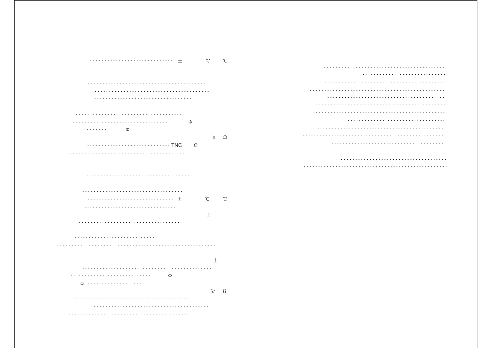
1.3 System Configuration and Application
1R
KP1TA transmitter
KP1R receiver
Here is one of the ways to configurate, connect the CD mixer or any audio
equipment as the input parts . And connect to the amplifier, loudspeaker,
recorder or any equipments as the output parts.
KP
Stereo Control
Mix Mode Control
Mono Control
Signal from
Audio Source
Signal from
Audio Source
1/L or 2/R
Signal from
Audio Source
1/L or 2/R
Signal from
Audio Source
Used for conventional stereo monitor mixes
Used for mixing and combining an individual mix between
two distinct monitor sends
Used when only one(mono) monitor mix is available
Stereo Mode
1R
KP
KP1TA Transmitter
Mix Mode
KP1TA Transmitter
Mono Mode 1
KP1TA Transmitter
Mono Mode 2
KP1TA Transmitter
KP1R Receiver
1R
KP
KP1R Receiver
1R
P
K
KP1R Receiver
R
1
P
K
KP1R Receiver
1/L or 2/R
1/L or 2/R
1/L or 2/R
4
9

2) Volume Limiter Setting: Short press set button
until LIM is flashing, then short press
button to turn on/off the LIM
function. To turn on this function which will display
as , it will limit the volume in a range. To
turn off this function which will display as .
3) Squelch Setting: Short press set button until
SQL is flashing, then short press
button to achieve the squelch setting.
4) Audio Balanced Setting: Short press set button
until EQ is flashing, then short press or
button to achieve the audio balanced setting.
Attention
When progress setting, if none of action will be done for 3 seconds, the
system will exit setting state automatically, and save the current setting.
2.4 Battery Installation for Receiver
1R
KP
1.4 Transmitter Function
(1) Volume Limiter Function: When turn on the v olume l imiter,i ft he v olume r each
the level which set before, the volume will not increase anymore, at the same
time, the limiter indicator will lights.
We suggest to turn on this function when using the system, it can protect the
user s audition and decrease the distortion.
To gain the best effect, turn on the transmitter, then adjust the output leve lo f
equipment until the volume limiter is flashing.
(2) Power:
(3) Gain Control Of Input Level : To the equipmen t i n lowe r outp ut leve l, operate
in +10dB.
(4) Input Jack:
RF Power 10dBM
RF Power 15dBM
RF Power 20dBM
Press the battery compartment door
follow the direction instruction to open
Install the batteries follow the battery direction
instruction which shown on the case of receiver
2.5 Receiver Function
(1) Volume Limiter Function:W hen t urn o nt hev olume l imiter, if t he v olume r each
the level which set before, the volume will not increase anymore.
We suggest to turn on this function when use the system , it ca n prote ct th e
user s audition and decrease the distortion.
(2) Audio Balanced Setting:
Alt up 6dB
Bourdon up 6dB
Alt & Bourdon up 6dB
Keep the original state
(3) Squelch Setting: When the signal is lower than the squelch setting, the signal
indicator will light off, and the audio output is in squelch state.
2.6 Headphone
(5) Input Connector:
Unbalanced Input Connector Balanced Input Connector
8
5

2. KP1R Receiver
2.1 Controls and Features
KP1R
A. Stereo / Mix Output
B. Volume Limiting Function
C. Signal Intensity
D. Level of Channel2/Audio Right
E. Level of Channel1/Audio Left
F. Frequency/Channel
G. Battery Indicator
H. Audio Balanced Setting
I. Squelch Setting
2.2 Receiver Control
1. Audio Left/Right Control.
In according to the indicator of receiver, rotate the
audio control knob to adjust the audio left/right
or channel 1/ 2.
When indicating dot on the knob is turned to the
mid-point, the audio left and right outputs are in
geometric proportion.
2. ON/OFF/VOLUME Control.
Rotate the ON/OFF/VOLUME knob to adjust the
volume.
3. Frequency/Channel Setting.
Length press the setting button or at
one blow, the frequency/channel will flash to enter
the state of frequency/channel setting.
1) Short press set button to replace between
frequency and channel.
2) Short press the setting button or ,
the frequency/channel will turn up/down a level.
3) Length press the setting button or ,
the frequency/channel will turn up/down continuously.
1. Antenna
2. Indicators of Antenna and Squelch: Indicates the signal of each channel.
3. Power On/Off and Volume control: Turn on the receiver and adjust the volume
of headphone.
4. Audio Control: To replace the audio left and right.
5. LCD: Display the working informations of receiver.
6. Set Button: To set and operate the receiver.
7. Headphone Jack: Connect the headphone.
8. Belt Clip.
9. Direction Guide of battery installation: To install the battery follow the direction
instruction.
10. Battery Compartment Door.
6
2.3 Receiver Setting
Short press set button to replace the states
between MIX LIM SQL EQ .
1) Mix/Stereo Output Setting: Short press set
button until MIX is flashing, then short press
button to turn on/off the MIX
function. Turn on this function which will display as
, it is the state of mix outputs to audio left
and right(L+R). If adjust the audio left and right
control knob in simultaneity, also can adjust the mix
ratio of audio left and right. To turn off this function
which will display as , meanwhile, it is the
state of stereo output.
7
 Loading...