

Page 1
QUICK INSTALL GUIDE
(Model Q-BA-3-1P-60)
Installing the Enphase Q Aggregator
To install the Enphase Q Aggregator, read and follow all warnings and instructions in this Guide and in the Enphase IQ Series Microinverter Installation and
Operation Manual at enphase.com/support. If you do not fully understand any of the concepts, terminology, or hazards outlined in these instructions, refer
installation to a qualied electrician or installer. These instructions are not meant to be a complete explanation of a renewable energy system. All installations
must comply with national and local electrical codes. Professional installation is recommended.
IMPORTANT: Enphase IQ Series Microinverters require the Q Cable and are not compatible with previous Enphase cabling. An IQ Envoy is required to
monitor performance of the IQ Microinverters. The Q Accessories work only with Enphase IQ Series Microinverters.
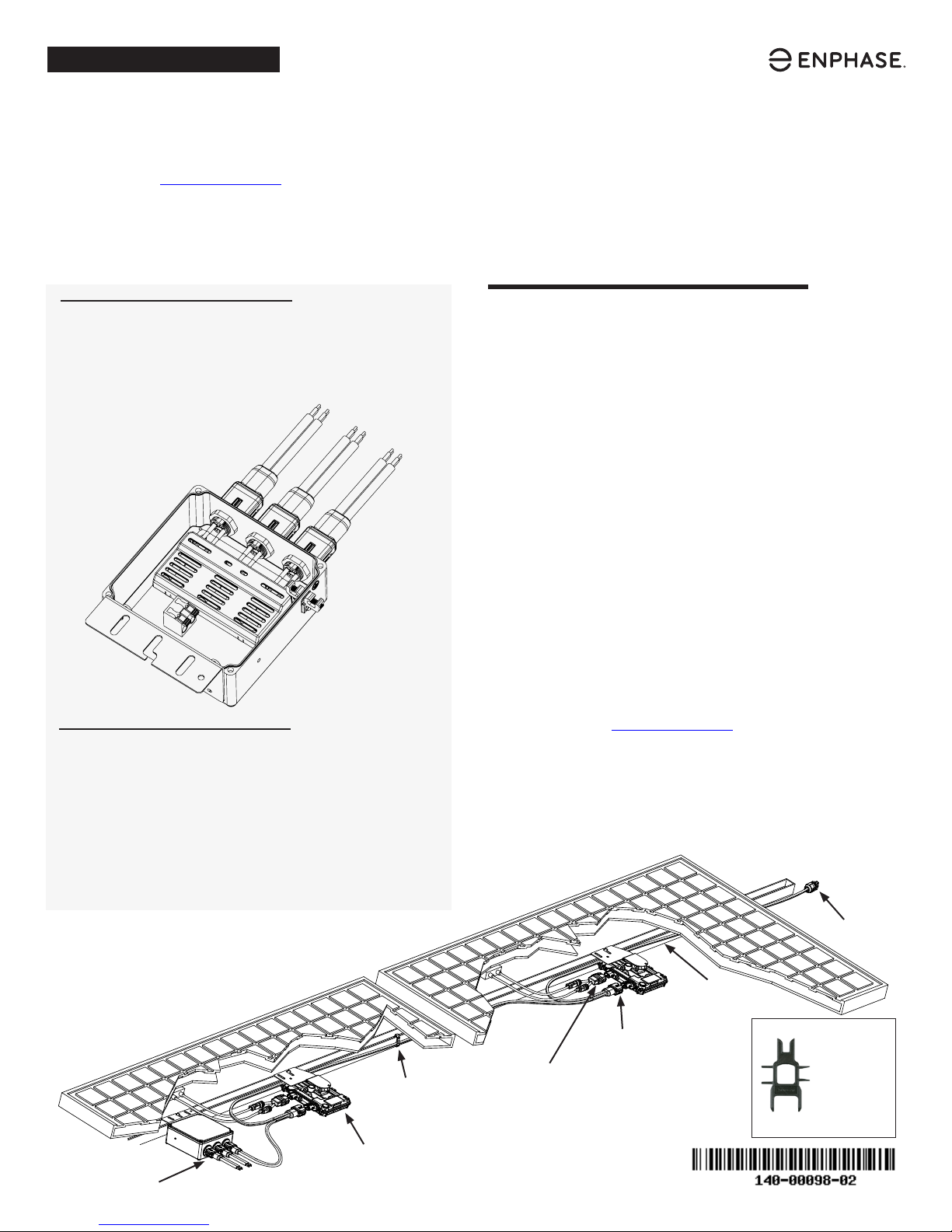
How It Works
Use the Enphase Q Aggregator to bring together up to three
branches of microinverters, center feed branch connections,
or connect a remote part of the array using Enphase Q Field
Wireable Connectors.
Features
•
Lets you install systems up to 11.5 kW with only two line
conductors and a ground coming from the roof
•
Usable in any position up to 45 degrees from horizontal
(NEMA 3R, includes drain holes)
•
The aggregator bracket is ready to install on rail, can be ipped
for roof or block mount installs, and allows you to t conduit
into either or both sides
PREPARATION
A ) Check the box for the following items:
•
Enphase Q Aggregator
•
One bulkhead connector cap (Q-BA-CAP). You may need to order an
extra cap if you connect only one branch circuit to the aggregator.
•
Quick Install Guide (this document)
B ) Check that you have these required items:
•
Enphase Q Aggregator(s) for multiple branch arrays
•
Drill with an appropriately sized hole saw for conduit entry
•
Wet/dry-rated conduit gland and conduit for home run entry
•
Screwdrivers
•
Wire stripping tool
•
Torque wrench and sockets for mounting hardware
•
75°C to 90°C copper conductors for connections between the Q
Aggregator and main PV breaker
•
Enphase disconnect tool
C ) Protect your system with lightning and/or surge suppression devices at
the sub or main panel.
D ) Protect the Q Aggregator with a maximum 60-amp over-current
protection device (OCPD).
E ) Size the AC wire gauge to account for voltage rise. Select the correct
wire size based on OCPD size and on the distance from the beginning
of the Enphase Q Cable to the breaker in the load center. Design for a
voltage rise total of less than 2% for the sections from the Enphase
Q Cable to the breaker in the load center. Refer to the Voltage Rise
Technical Brief at enphase.com/support for more information.
Best practice: Use a Q Aggregator and Enphase Q Field Wireable
Connectors to center-feed each branch circuit to minimize voltage rise
in a fully-populated branch.
F ) Plan to install the Q Aggregator in a location that will be under the
modules when the array is complete.
Enphase Q
Aggregator
AC connections
Cable clips or
tie wraps
Enphase
IQ 6 Micro or
IQ 6+ Micro
DC connectors
terminator
Enphase
Q Cable
AC connector
Enphase
disconnect
tool
Page 2

INSTALLATION
1
Plan the Connections
A ) Plan for the following connections:
• One maximum 60 A home run: Pass the home run cable through wet/
dry-rated conduit gland, and secure in the cage clamp lugs to the terminal
connectors. Use standard home run conduit size (1/2, 3/4, or 1-inch).
• Up to three 20 A branch circuits: Three bulkhead mounted connectors
allow for the direct connection of the Q Cable.
• PV Array ground: The ground lug connection that passes through the
enclosure allows you to connect racking and module ground to the main
panel ground. The Aggregator contains no parts requiring a ground.
2
Plan the Location
A ) Select a location that will be under the modules when the array is
complete, but that will also be accessible for making connections later.
B ) Ensure that you can bring conduit into the Q Aggregator from the upper
left or right side where indicated by pilot hole indents.
BEST PRACTICE: Lay out your cable runs before determining the
Q Aggregator location.
WARNING: Ensure the conduit does not enter from an uphill
*
direction and that moisture does not enter the Aggregator. Water
ingress will void the warranty for the Aggregator.
3
Drill a Hole for Conduit
A ) Prep conduit with an offset to approximate area and position the Q
Aggregator to double check your drill location.
B ) Remove the Q Aggregator cover and drill a hole for up conduit: Typical
openings are 2.2 cm, 2.8 cm, or 3.5 cm (0.885”, 1.115”, or 1.362”), but
check the conduit ttings you are using to verify size.
WARNING: Take care not to damage the circuit board.
*
C ) Dump or blow out any debris from this drilling operation.
5
Wire the Q Aggregator
A ) Pull the line conductors and ground up to the Q Aggregator.
B ) Strip the two line conductors (18 mm/0.7” strip length) using the guide
on the upper surface of the cage clamp style main lugs.
C ) Secure the conductors (12 AWG to 4 AWG max) in these lugs and make
sure that the orange handles are in the fully down position.
D ) Strip and bring the ground wire inside the Q Aggregator to the ground
lug. This ground lug passes through to outside for use in grounding the
rack and modules as needed.
E ) Secure racking ground to the ground lug.
F ) Torque the ground connections as follows:
• 14-10 AWG: 2.25 N m (20 in-lbs)
• 8 AWG: 2.82 N m (25 in-lbs)
• 6-4 AWG: 3.95 N m (35 in-lbs)
G ) Check your connections for soundness.
You have completed the wiring for up to three plug and play branch circuits
in your system.
6
Replace the Cover
A ) Make sure that the drain holes on the bottom of the Q Aggregator are
free from debris.
B ) Check the seal on all sides for trapped debris. Remove any debris, if
needed.
C ) Replace the cover on the Q Aggregator and torque screws to 1.1 N m
(9.7 in-lbs).
D ) Check that the Q Aggregator is properly sealed.
E ) Cap any unused branch circuit connections.
The Q Aggregator is now ready for branch circuit connections.
DANGER! Never connect a single branch circuit to multiple branch
+
circuit connections on the Q Aggregator.
Attach the Q Aggregator to the PV Rail
4
WARNINGS:
*
• Install the Q Aggregator under the PV module to avoid direct exposure
to rain, UV, and other harmful weather events.
• Mount the Q Aggregator with adequate clearance from the roof
surface for rain and snow resistance.
• Always install the Q Aggregator with the label side up. Do not mount it
upside down. You can ip the bracket for roof or block mounting.
• When transitioning between rows, secure the cable to the nearest rail
to prevent cable damage.
A ) Install Q Aggregator on rail in a location that does not conict with the
module frame and module mounting hardware. Allow a minimum of 1.9
cm (0.75“) between the roof and the Q Aggregator. Also allow 1.3 cm (0.50“)
between the back of the PV module and the top of the Q Aggregator.
B ) Install the Q Aggregator on the rail and mount loosely.
C ) Use a ttings rated for outdoor use to secure the conduit or Q cable to
the Q Aggregator.
D ) Provide an AC connection (home run) from the Enphase Q Aggregator
back to the electricity network connection using equipment and
practices as required by local jurisdictions.
E ) Tighten rail connections to 80 in-lbs (9 N m), and make sure that conduit
ttings are secured and water tight.
F ) Secure and check all connections.
To remove a sealing cap or AC connector, you must use an
Enphase disconnect tool.
Each Q Aggregator includes one bulkhead connector cap. You can
purchase additional caps from your distributor.
Page 3

TROUBLESHOOTING
DANGER! Risk of electric shock. Some tasks are done with live
+
circuits in an outdoor rooftop environment. Always wear proper
personal protective equipment (PPE) for electrical and rooftop tasks.
One or More Branches Not Generating
Without removing the cover:
A) Verify that voltage is within range at the PV breaker at the main panel
when measuring from L1 to L2.
B) Power off the PV circuit (aggregated ac circuit) and use a voltmeter to
verify that the circuit is turned off. Use Lockout/Tagout procedures.
C) On the roof, disconnect the Q Cable connectors from all (up to three) of
the branch circuit bulkhead connectors on the Q Aggregator and seal
connectors.
D) Turn the PV circuit on at the main panel and again verify that 240V is
present from L1 to L2.
E) Using PPE, and taking care not to short the L1, L2 pins within each
connector, use a voltage meter to determine if each connector on the Q
Aggregator has 240V present from L1 to L2.
F) If all connectors show proper voltage then the Q Aggregator is working
correctly.
G) If some connectors exhibit proper voltage, but, after repeated testing,
other connectors do not exhibit proper voltage, continue to the Q
Aggregator board removal and replacement procedures.
H) If all connectors do not show voltage and the main PV circuit from the
main panel is active per step D, continue with the following troubleshoot-
ing procedure.
I) Reconnect, secure, and check all connections.
All Circuits Appear Non-Functioning
A) Verify that the PV breaker at the main panel reads 240V when measur-
ing from L1 to L2.
B) Power off the PV circuit (aggregated ac circuit) and verify with voltmeter
that the circuit is turned off. Use Lockout/Tagout procedures.
C) At the Aggregator, open the Q Aggregator using a standard screwdriver
blade on the four captured screws on the cover.
D) Use a voltmeter or electrical tester to verify that the circuit coming to the
main lug of the Q Aggregator is not live.
E) Inspect the Q Aggregator for evidence of loose connections at the main
lug or look for evidence of multiple blown fuses. Keep in mind that fuse
ends may be coated. It is best to test from the main lugs to the spade
terminals.
F) Remove tools and/or screws from the Q Aggregator, reactivate the PV
circuit (aggregated ac circuit), and test for voltage on the conductors
coming from main panel.
G) If no voltage is coming from the main panel check your electrical wiring
from the main panel.
H) If there is voltage at Q Aggregator main lug, and if the wires appear to
be stripped appropriately and terminated with orange handles down,
continue to the Q Aggregator board removal and replacement proce-
dures.
Page 4

SAFETY
IMPORTANT SAFETY INSTRUCTIONS.
SAVE THIS INFORMATION. This guide contains important instructions to follow during installation of the Enphase Q Aggregator.
WARNING: Hot internal surfaces.
WARNING: Refer to safety instructions.
DANGER: Risk of electric shock.
Safety Symbols
DANGER: This indicates a hazardous situation, which if not avoided, will
+
result in death or serious injury.
WARNING: This indicates a situation where failure to follow instructions
*
may be a safety hazard or cause equipment malfunction. Use extreme
caution and follow instructions carefully.
WARNING: Risk of burn. Failure to follow instructions may result in burn
;
injury.
NOTE: This indicates information particularly important for optimal system
✓
operation.
Safety Instructions
DANGER: Risk of electric shock. Do not use Enphase equipment in a manner
not specied by the manufacturer. Doing so may cause death or injury to
+
persons, or damage to equipment.
DANGER: Risk of electric shock. Be aware that installation of this equipment
includes risk of electric shock. Do not open without rst removing AC
+
power from the Enphase System. Disconnect the power coming from the
photovoltaics before servicing or installing.
DANGER: Risk of electric shock. Risk of re. Before making any connections
verify that the circuit breakers are in the off position. Double check all wiring
+
before applying power.
DANGER: Risk of electric shock. Risk of re. Only use electrical system
components approved for wet locations, including but not limited to conduit
+
ttings.
DANGER: Risk of electric shock. Risk of re. Use the circuit in the Enphase
Q Aggregator only for connecting Enphase Q Cable and Microinverters. No
+
other loads or sources are allowed.
DANGER: Risk of electric shock. Risk of re. Only qualied personnel should
install, troubleshoot, or replace the Enphase Q Aggregator.
+
DANGER: Risk of electric shock. Improper servicing of the Q Aggregator or
its components may result in a shock, re or explosion. To reduce these
+
risks, disconnect all wiring before attempting any maintenance.
DANGER: Risk of electric shock. Risk of re. Ensure that all AC and DC wiring
is correct and that none of the AC wires are pinched, shorted, or damaged.
+
DANGER: Risk of electric shock. Risk of re. Protect the Q Aggregator with a
60 A maximum over current protection device (OCPD).
+
DANGER: Risk of electric shock. Risk of re. Do not attempt to repair the
Enphase Q Aggregator, other than to replace parts only as directed in this
+
guide. Tampering with the board or damaging the conformal coating will
void the warranty.
DANGER: Risk of electric shock. Risk of re. Make sure the conductors
are not damaged. If the exposed wires are damaged, the system may not
+
function properly.
DANGER: Risk of electric shock. Risk of re. Do not leave AC connectors
on the Enphase Q Cable uncovered for an extended period. You must
+
cover any unused connector with a sealing cap.
DANGER! Risk of electric shock. Some tasks are done with live circuits in
an outdoor rooftop environment. Always wear proper personal protective
+
equipment (PPE) for electrical and rooftop tasks.
WARNING: Ensure the conduit does not enter from an uphill direction and
that moisture does not enter the Aggregator. Water ingress will void the
*
warranty for the Aggregator.
WARNING: Do not expose any connectors to rain or condensation before the
connectors are mated.
*
WARNING: Install the Q Aggregator under the PV module to avoid direct
exposure to rain, UV, and other harmful weather events; mount the Q
*
Aggregator off of the roof surface for rain and snow resistance; and
always install the Q Aggregator with the label side up. Do not mount it
upside down.
WARNING: Risk of equipment damage. This product is intended for
operation in an environment having a maximum ambient temperature of
*
55ºC (131ºF).
WARNING: When installing the Enphase Q Cable, secure any loose cable to
minimize tripping hazard.
*
WARNING: Before installing or using the Enphase Q Aggregator, read all
instructions and cautionary markings in the technical description, on the
*
Enphase System, and on the photovoltaic (PV) equipment.
WARNING: Risk of skin burn. The Enphase Q Aggregator may have very hot
;
interior surfaces. To reduce risk of burns, use caution when working with the
Q Aggregator.
NOTE: For problems other than a blown fuse or physical damage, contact
✓
Enphase customer service to obtain an RMA (return merchandise authorization) number and start the replacement process.
NOTE: Install the Q Aggregator in the eld with 75°C or 90°C copper
✓
conductors sized per local code requirements and voltage drop/rise
considerations.
NOTE: Using unapproved attachments or accessories may result in damage
✓
or injury.
NOTE: Use Class 1 wiring methods for eld wiring connections to
✓
terminals of a Class 2 circuit. Use only 14 to 4 gauge wire. Select the wire
gauge used based on the protection provided by the circuit breakers/
fuses. Overcurrent protection must be installed as part of the system
installation.
NOTE: When looping the Enphase Q Cable, do not form loops smaller than
✓
4.75 inches (12 cm) in diameter.
NOTE: Perform all electrical installations in accordance with all applicable
✓
local electrical codes: the Canadian Electrical Code, part 1; the National
Electrical Code (NEC); ANSI requirements; and NFPA 70.
NOTE: To ensure optimal reliability and to meet warranty requirements,
✓
install the Enphase Microinverters and Enphase Q Cable according to the
instructions in this guide.
NOTE: Protection against lightning and resulting voltage surge must be in
✓
accordance with local standards.
Enphase Customer Support: enphase.com/en-us/support/contact
© 2018 Enphase Energy, Inc. All rights reserved.
 Loading...