

enphase Microinverter System Reference Manual
Reference Manual
Troubleshooting an
Enphase Microinverter System

Contents
Enlighten Messages and Alerts 4
ACFOOR (AC Frequency Out of Range) 4
ACVOOR (AC Voltage Out of Range) 5
Critical Temperature 7
DC Too Low 8
DC Too High 8
Envoy/EMU not Reporting 9
Gateway Failure 9
GFDI / GFI trip 9
Grid Gone 10
Module Failed to Report 11
Over Temperature 11
Zigbee Device Failed to Report 11
Zigbee USB Stick Removed 11
ENVOY and Communications Issues 12
General Envoy Issues 12
A physical Ethernet connection is not practical at this site 12
LCD is completely blank 12
LCD displays “Reset Clock” 12
LCD displays “Envoy Failure” 12
Internet Problems (Local Area Networking) 13
LCD shows a non-routable/self-assigned IP address and also shows “-Web” 13
LCD periodically shows “-Web” for minutes or hours at a time. 14
LCD shows a good IP, but also shows “-Web” 15
The DSL modem at the site has only one Ethernet port, and it is being used 15
The Envoy cannot get a “+Web” even though all premises networking is intact 15
Internet service is not available on site 15
Can I use a dial up Internet connection with the Envoy? 16
Are My Power Line Communication Bridges Working? 16
The Envoy is using a static IP and cannot get a web connection 17

Communication Issues between Envoy & Microinverters (Power Line Communication) 17
Inverters are not detected / Power line communication level is low/poor 18
How to identify an interfering load 20
This is a Line-side Tap (or Supply-Side, or PLC) Installation 21
When do I need an additional Envoy? 22
How to get further training on Enphase power line communication 22
Microinverter / PV Module Issues 23
Microinverter LEDs and What they Mean 23
The Microinverter LEDs are blinking red 23
The Microinverter LEDs are blinking orange 24
The Microinverter LEDs are not lit 24
Power Production 25
The unit under review shows low production. 25
Why is one unit showing 0W production when adjacent units are productive? 25
My panels are dark in Enlighten and no production value is displayed 28
Enlighten will not allow me to select the panel 28
I would like to see my panel’s production history 28
Run a report to view production history 28
Use the Graph widget to view production history 29
There is an event or alert message on the system 29
Troubleshooting An Enphase Installation
This document describes trouble-shooting ows and procedures only. For product and installation information, refer to http://www.enphase.com/support/downloads.
Troubleshooting areas covered in this document include:
Enlighten Messages and Alerts
ENVOY and Communications Issues
Microinverter / PV Module Issues
Enlighten Messages and
Alerts
The following event messages may appear
in Enlighten or in the Envoy interface. If you
have received an Enlighten alert in email,
read the email through. It includes information on whether or not action is required and
what that action should be.
ACFOOR (AC Frequency Out of Range)
The inverter reports that the frequency coming from the utility is
either too low or too high as specied by UL standards (UL1741).
The nominal frequency range for M190, M210 and D380 microinverters is 59.3 to 60.5; typical is 60.0.
Frequency out of range events are usually transient and indicate
an anomaly from the utility; usually this is self-correcting by the
utility. If the condition persists, troubleshoot as follows.
These events can happen because of an actual frequency outof-spec condition, but more likely, they trip because of either a
poorly shaped AC waveform or excessive THD (Total Harmonic
Distortion) emanating from the utility service. This type of error rarely affects just one unit, and is usually indicative of an AC
service issue.
Along with ACFOOR events, Grid Gone events may also be occurring. This is an indication of Anti-Islanding, which sometimes
What does “AntiIslanding” mean?
“Anti-islanding” is protection against the continuous operation of the
inverter and part of the
utility load while isolated
from the remainder of the
electric utility system.
This means that if power
from the utility is disconnected, the utility-interactive inverter will stop
exporting power within
two seconds. This is to
protect utility line workers
and loads.
goes hand-in-hand with ACVOOR (AC Voltage Out of Range) and
ACFOOR.
4 Copyright © Enphase Energy, Inc. 2011 06/15/2011

ACVOOR (AC Voltage Out of Range)
The inverter reports that the AC voltage coming from the utility is either too low or too high
as specied by UL standards (UL1741).
Acceptable ranges for AC service are shown in the table below:
240 Volt AC Split Phase 208 Volt AC Three Phase
L1 to L2 211 to 264 Vac L1 to L2 to L3 183 to 229 Vac
L1, L2 to neutral 106 to 132 Vac L1, L2, L3 to neutral 106 to 132 Vac
This condition should correct itself, as there are often periodic variations in Utility voltage. If
the condition persists, troubleshoot as follows.
When an entire branch or multiple branches are impacted
Things to check:
1. Measure voltages for L-L and L-N for all phase-conductors at the service entrance (PCC),
at each Enphase branch circuit breaker, at each Enphase branch circuit junction box, at
each Enphase branch circuit AC pigtail (if used in this installation), and at the last microinverter of each Enphase branch circuit.
2. Verify that the AC pigtail or cabling to the junction box is correctly terminated per wire
color. (See the installation manual for the microinverter being used.)
3. Verify that the correct circuit breaker has been used. (Is the amperage rating correct?
Are the number of termination poles correct?)
• If the breaker is undersized, the branch may experience nuisance tripping at peak
production times.
• If the breaker is oversized, the branch may have been damaged with too much
current ow through the microinverters.
5 Copyright © Enphase Energy, Inc. 2011 06/15/2011
4. Verify that the service entrance power is not coming from a 240 Vac “DELTA” or 240 Vac
“STINGER” secondary transformer.
5. Make sure that the site does not have undersized conductors, either to the Enphase
branch circuit or between the primary load center and the subpanel (if a subpanel exists).
• In the case where the array branch circuits land on a PV subpanel, and there is additional wire run back to the main service tie-in, additional voltage drop calculations
must be completed. A typical voltage drop limit is 3% for AC branch circuits; however,
this is not adequate for utility-interactive inverters. Enphase recommends a voltage
drop of less than 1.5 volts or 0.6 percent.
• For more information, refer to our Application Note “Voltage Drop Calculations: http://
www.enphase.com/support/downloads.
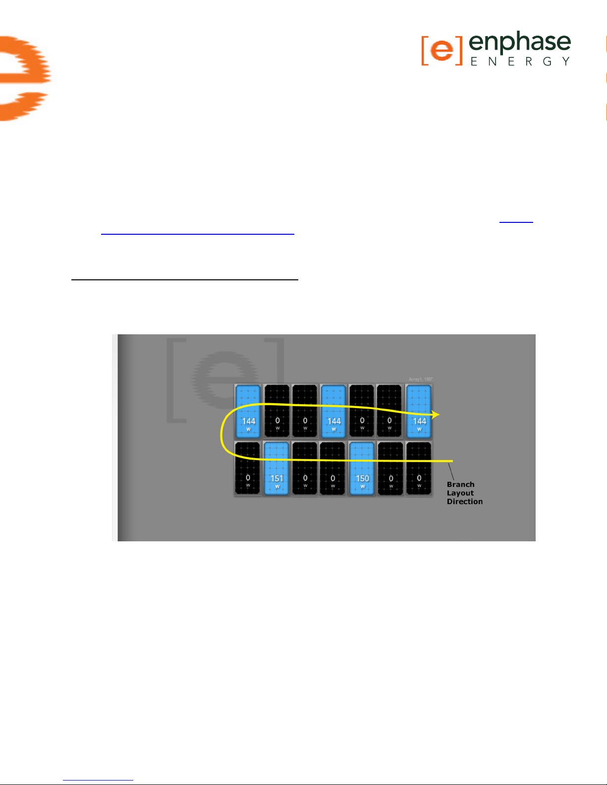
When only a few microinverters are impacted
1. If the condition alternates among microinverters, incorrect cabling may be in use. The
following Enlighten snapshot shows the result of using 208 Volt cabling at a site with 240
Volt service. Notice that only every third unit is productive.
2. If there is only one unit affected by the ACVOOR, and the condition persists with consistent, out of spec readings, the problem is likely with the microinverter, and it may need
to be replaced.
3. If there are multiple units consistently affected by ACVOOR events, this is most likely
caused by an installation/wiring error during installation.
• If the affected units are contiguous or if an entire branch is affected, there is probably
an On/Off switch, or a homemade AC combiner, or an incompatible AC disconnect inbetween the circuit breaker and the AC pigtail of the PCU branch circuit. Or, it may be
faulty wiring, terminations, or circuit breakers only for those affected Enphase branch
circuits. Sometimes something as simple as a wire terminated on a circuit breaker
that is not screwed down tightly will cause ACVOOR on a given branch circuit.
• It may be that an AC pigtail is defective, or that it’s AC connector (or one of the
microinverters on the branch’s AC connector) is damaged or defective. If, for example,
6 Copyright © Enphase Energy, Inc. 2011 06/15/2011

on a branch circuit the rst three units are ne, but the remaining 8 or 9 units on the
branch are in a state of ACVOOR, there is something wrong either at location #3 or
#4 in the branch circuit, affecting the AC Voltage from that point and on downstream
into the branch circuit.
• If the ACVOOR is not an installation or wiring defect, and there are multiple units impacted on an intermittent basis, it may be that the site’s utility service is simply high.
One of the following may be causing this on the utility side:
- The utility transformer bringing service to the site is damaged or defective.
- The utility is purposely pushing the higher AC voltage into some areas during
times of peak demand.
- The homerun conductors from the Enphase branch circuits to their respective
circuit breakers are undersized. For more information, refer to the Application
Note on Voltage Drop Calculations: http://www.enphase.com/downloads
- Is the site using a step-up transformer in-between the primary load-center
and the Enphase branch circuits? If so, this can create ACVOOR conditions.
• If all of the above have been checked and veried, and ACVOOR nuisance tripping is
still occurring, and neither the installer nor the utility can mitigate, Enphase can upgrade all of the microinverters to a parameter table which allows for slightly expanded
trip-points, while still remaining within spec.
Critical Temperature
This rare condition occurs if the inverter reports an internal temperature that exceeds it
rated range. It reacts by producing less power to reduce internal temperature. Once the
internal temperature of the inverter diminishes, the microinverter resumes full power
production and the error message will clear. No action is required unless the condition
persists. If it persists, contact Enphase Energy customer support.
This reects internal temperature coming from a sensor inside the microinverter, not the
ambient temperature. For more information, see the Enphase Technical Brief on temperature: http://www.enphase.com/downloads
7 Copyright © Enphase Energy, Inc. 2011 06/15/2011

DC Too Low
The inverter reports that DC input voltage from the PV module is too low. This is a normal
condition that occurs in the morning and in the evening, but during the day may results
from any of the following conditions:
• This message can appear during extended periods of low solar irradiance (for example, a
period that includes the night hours plus a few hours of low sunlight after sunrise).
• This event may indicate a bad or missing DC connection to the inverter. If this condition
occurs during daylight hours, we recommend that a qualied electrician inspect the DC
connection between the module and the inverter. The connection may need to be tightened or may be experiencing wear and tear and require replacement.
• If the microinverter is having DC Too Low events during daylight hours, it may have
been paired with an incompatible PV module. Is the PV module on the Enphase Compatibility list? If the PV module is not compatible it may work sometimes, but will not work
consistently or effectively. Some incompatible PV modules will not produce enough DC
to start up the microinverter. To check DC input measurements to a microinverter, see
“Check DC measurements” in this document.
• Is it producing at all, or does it show zero production? If it shows zero production, does
the site use adaptors (or jumpers) between the PV module and the microinverter? It
may be that polarity is reversed. Verify by measuring the PV modules VOC (Open Circuit
Voltage) and inspect the positive and negative markings on the PV module and microinverter.
• To determine if the problem is with the microinverter or with the PV module, it may be
necessary to swap the DC leads from the suspect unit and an adjacent unit. If after
checking Enlighten periodically (this may take up to 30 minutes), the problem moves to
the adjacent module, this indicates that the PV module isn’t functioning correctly. If it
stays in place, the problem is with the microinverter. Call Enphase Customer for help in
reading most current microinverter data and for help in obtaining a replacement microinverter, if needed.
Never rule out the possibility of a damaged or defective PV module. They are somewhat
fragile, directly exposed to the elements, and have a very long service-life expectation.
The glass on the surface of the PV module can become cracked, lowering the PV module’s output or causing it to trip a “Ground Fault” (GFI).
DC Too High
The inverter reports that DC input voltage from the PV module is too high.
• If the microinverter is having DC Too High events, it may have been paired with an incompatible PV module. It may be that the PV module generates a higher voltage than is
recommended for the inverter. Check that the PV module and inverter are compatible by
referring to the Module Compatibility List: http://www.enphase.com/support/downloads.
• If the DC Too High is being reported across multiple units, and incompatible PV modules
have been ruled-out, contact Enphase customer support to verify the rmware version
running on the microinverters.
8 Copyright © Enphase Energy, Inc. 2011 06/15/2011

Envoy/EMU not Reporting
The broadband Internet connection that the Enphase Envoy uses to communicate to the
Enlighten servers is experiencing a problem.
If the Envoy displays a status of –Web in the LCD window, it is not currently communicating
with the Enlighten servers. The Internet service may be down or the router may be unplugged or turned off.
Internet connections often have temporary outages. If the situation persists, contact your
ISP (Internet Service Provider). When the connection is restored, the Enphase Envoy communication gateway will catch up with the transmission of all energy data it has stored.
• It could be that Internet service is dropping out periodically. Call your ISP if you notice
that other devices at the site are also losing Internet connectivity.
• Do you have dial up Internet service? Dial up internet service is not supported on the
Envoy.
• The Envoy may have an internal error, see “General Envoy Issues”.
• See “2. Did the Envoy previously have an Internet connection at this site?”
Gateway Failure
The Envoy has detected a software problem. To clear this message:
Unplug the Envoy from the electrical outlet and then plug it back in. Do this only once. If it
returns to failure mode, contact Enphase Customer Support.
GFDI / GFI trip
A microinverter has detected ground fault current greater than one amp on the DC side.
You can attempt to clear this condition through the Envoy Interface by sending the ClearGFI message to the affected microinverter.
If the Envoy is on a Local Area Network, you can access it from another computer which is
also on that same LAN (start with step 4 below). If the Envoy is not on a LAN, then you can
directly connect an Ethernet cable between the Envoy and your laptop by performing all of
the following steps:
1. Connect one end of the Ethernet cable supplied with the Envoy to the Ethernet port on
the Envoy (or browse to it on your Local Area Network).
2. Connect the other end of the Ethernet cable to the RJ45 network port of the computer.
3. Open the Internet browser application on the computer.
4. In the browser address window, enter the IP address displayed in the Envoy’s LCD window (e.g., 192.168.1.101).
5. If you fail to make a connection at this point, you can manually congure your subnet to
169.254.120.2 and subnet mask to 255.255.0.0.
6. Once the browser has successfully connected with the Envoy, the home screen is displayed in the browser window.
9 Copyright © Enphase Energy, Inc. 2011 06/15/2011
 Loading...