

enphase M250 Quick Install Manual
M250 SAFETY
M250 (M250-60-2LL) Safety
Important Safety Information
This document contains important instructions to use during installation of the Enphase M250 Microinverter™. To reduce
the risk of electrical shock, and to ensure the safe installation and operation of the Enphase Microinverter, follow these instructions. The following safety symbols and information indicate dangerous conditions and important safety instructions.
®
Product Labels
WARNING: Hot surface.
DANGER: Risk of electrical shock.
Refer to product instructions.
Safety Instructions
DANGER: Before installing or using the Enphase Micro-
inverter, read all instructions and cautionary markings in
the technical description, on the Enphase Microinverter
System, and on the photovoltaic (PV) equipment.
DANGER: Do not use Enphase equipment in a manner
not specied by the manufacturer. Doing so may cause
death or injury to persons, or damage to equipment.
DANGER: Risk of Electrical Shock. Be aware that installation of this equipment includes risk of electric shock.
Do not install the AC junction box without rst removing
AC power from the Enphase System.
DANGER: The Engage Cable terminator cap must not
be installed while power is connected.
DANGER: Electric shock hazard. The DC conductors
of this photovoltaic system are ungrounded and may be
energized.
WARNING: Always de-energize the AC branch circuit
before servicing. Never disconnect the DC connec-
tors under load. Disconnect DC connections rst, then
disconnect AC connections.
WARNING: The body of the Enphase Microinverter is
the heat sink. Under normal operating conditions, the
temperature is 15°C above ambient, but under extreme
conditions the microinverter can reach a temperature of
80°C. To reduce risk of burns, use caution when working with microinverters.
WARNING: The M250 may be paired only with a 60-cell
PV module. The PV module DC conductors must be la-
⚠
beled “PV Wire” or “PV Cable” to be compliant with NEC
690.35(D) for Ungrounded PV Power Systems.
Safety and Advisory Symbols
DANGER! This indicates a hazardous situation, which if
not avoided, will result in death or serious injury.
WARNING! This indicates a situation where failure to
⚠
✓
⚠
⚠
⚠
⚠
⚠
⚠
⚠
⚠
follow instructions may be a safety hazard or cause
equipment malfunction. Use extreme caution and follow
instructions carefully.
WARNING! This indicates a situation where failure to
follow instructions may result in burn injury.
NOTE: This indicates information particularly important for optimal system operation. Follow instructions
closely.
WARNING: If the AC cable on the microinverter is damaged, do not install the unit.
WARNING: You must match the DC operating voltage
range of the PV module with the allowable input voltage
range of the Enphase Microinverter: 16-48V.
WARNING: The maximum open circuit voltage of the PV
module must not exceed the specied maximum input
voltage of the Enphase Microinverter: 48V DC.
WARNING: The M250 has eld-adjustable voltage and
frequency trip points that you may need to set, depending upon local requirements. Only an authorized installer
with the permission and following requirements of the
local electrical authorities should make adjustments.
WARNING: Only use electrical system components approved for wet locations.
WARNING: Only qualied personnel should trouble-
shoot, install, or replace Enphase Microinverters or the
Engage Cable and Accessories.
WARNING: Make sure protective sealing caps have
been installed on all unused AC connectors. Unused AC
connectors are live when the system is energized by the
grid. Sealing caps may not be reused.
WARNING: Ensure that all AC and DC wiring is correct
and that none of the AC or DC wires are pinched or
damaged. Ensure that all AC junction boxes are properly
closed.
WARNING: The microinverter must be installed under
the module, out of rain and sun. Do not mount the micro-
⚠
inverter in a position that allows long-term exposure to
direct sunlight or in a vertical orientation that allows water
to collect in the DC connector recess. Do not install the
microinverter black side up or vertically, with the DC connectors facing up.
WARNING: When installing the Engage Cable, secure
any loose cable to minimize tripping hazard.
⚠
WARNING: Do not leave AC connectors on the Engage
Cable uncovered for an extended period. If you do not
⚠
plan to replace the microinverter immediately, you must
cover any unused connector with a sealing cap. Sealing
caps may not be reused.
WARNING: Do not exceed the maximum number of
microinverters in an AC branch circuit as listed in the
⚠
manual. You must protect each microinverter AC branch
circuit with a 20A maximum breaker.
WARNING: Do not connect Enphase Microinverters to
the grid or energize the AC circuit(s) until you have com-
⚠
pleted all of the installation procedures and have received
prior approval from the electrical utility company.
WARNING: Do not attempt to repair the Enphase Microinverter; it contains no user-serviceable parts. If it fails,
⚠
contact Enphase customer service to obtain an RMA
(return merchandise authorization) number and start the
replacement process. Tampering with or opening the
Enphase Microinverter will void the warranty.
WARNING: Be aware that only qualied personnel must
connect the Enphase Microinverter to the utility grid.
⚠
WARNING: The Engage Cable terminator cap is
intended for one-time use only. If you open the termina-
⚠
tor after initial installation, the latching mechanism is
destroyed and the terminator cap cannot be used again.
If the latching mechanism is defective, the terminator
must not be used. The latching mechanism must not be
circumvented or manipulated.
WARNING: When stripping the sheath from the Engage
Cable, make sure that the conductors are not damaged.
⚠
If the exposed wires are damaged, the system may not
function properly.
WARNING: Perform all electrical installations in accordance with all applicable local electrical codes and the
⚠
National Electrical Code (NEC), ANSI/NFPA 70.
NOTE: Check the labeling on the Engage Cable drop
✓
connectors to be sure that the cable matches the electrical utility service at the site. Use 208 VAC (208 VAC
three-phase) Engage Cable at sites with three-phase 208
VAC service, or use 240 VAC Engage Cable at sites with
240 VAC single-phase service.
NOTE: There are two release-holes in the drop con-
✓
nector on the cable. These are not for mounting but are
used to disconnect the connector. Keep these release
holes clear and accessible.
NOTE: Protection against lightning and resulting voltage
✓
surge must be in accordance with local standards.
NOTE: Many PV modules have a central stiffening brace.
✓
In these cases, do not position the connector and microinverter at the exact center of the PV module. Instead,
position the drop connectors so that the connectors do
not conict with the braces.
NOTE: If you need to remove a sealing cap, you must
✓
use the Enphase disconnect tool or a #3 Phillips screwdriver. Sealing caps may not be reused.
NOTE: The M250 works with 240 VAC single-phase util-
✓
ity service or with 208 VAC three-phase utility service
NOTE: When installing the Engage Cable and accesso-
✓
ries, adhere to the following:
• Do not expose the connection to directed, pressurized
liquid (water jets, etc.).
• Do not expose the connection to continuous immersion.
• Do not expose the AC connector to continuous tension
(e.g., tension due to pulling or bending the cable near
the connection).
• Use only the connectors and cables provided.
• Do not allow contamination or debris in the connectors.
• Use the cable and connectors only when all parts are
present and intact.
• Fit the connections using only the prescribed tools.
• Use the terminator to seal the conductor end of the
Engage Cable; no other method is allowed.
NOTE: Do not use the shipping cap to cover unused
✓
connectors. The shipping cap does not provide an
adequate environmental seal. Enphase sealing caps
are required for the system to be UL compliant and to
protect against moisture ingress.
NOTE: Completely install all microinverters and all sys-
✓
tem AC connections prior to installing the PV modules.
Installation Map
You can build the system map manually, or you can use the
ArrayGun feature from the Enphase Installer Toolkit to easily
build and congure a system. For more information, refer to
http://enphase.com/products/arraygun.
To manually build the Installation Map:
• Peel the removable serial number label from each
microinverter and afx it to the respective location on the
installation map.
• Peel the label from the Envoy and afx it to the installation
map.
• Log in to Enlighten.
• Scan the installation map and upload it to the System
Activation form online.
• Use Array Builder to create the virtual array using the
installation map as your reference.
• To see the Array Builder demo, refer to
http://enphase.com/support/videos.
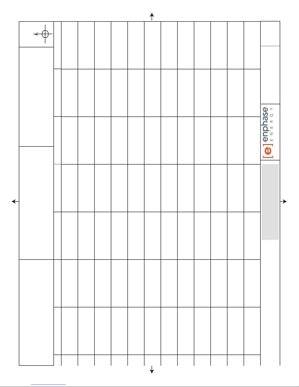
N S E W
(circle one)
To Sheet: ________
04
REVISION:
140-00003
DOCUMENT NUMBER:
INSTALLATION MAP
Installer information:Customer information:
To Sheet: ________
ENPHASEENERGY.COM
Envoy Serial Label
To Sheet: ________
1 2 3 4 5 6 7
Panel Group:
Azimuth:
Tilt:
sheet _____ of _____
A
B
C
D
E
F
G
H
J
To Sheet: ________
K
L
M
Scan completed map and upload it to Enphase. Click
“Add New System” at www.enlighten.enphaseenergy.com.
Use this map to build the virtual array in Enlighten’s Array Builder.
 Loading...