

enphase M215-60-2LL-S22-IG, M250-60-2LL-S22, M250-60-2LL-S25, M250-72-2LL-S22, M250-72-2LL-S25 Quick Install Manual
...Page 1
QUICK INSTALL GUIDE
Installing Enphase M250 and M215 Microinverters
To install the Enphase M250 and M215 Microinverters™ read and follow all warnings and instructions in this guide and in the Enphase M250 and M215
Microinverter Installation and Operation Manual at: enphase.com/support. Safety warnings are listed on the back of this guide.
Because ground fault protection (GFP) is integrated into the M250 and M215 microinverters, the models listed in this guide do not require a grounding electrode conductor (GEC) between microinverters. To support GFP, use only PV modules equipped with DC cables labeled PV Wire or PV Cable.
PREPARATION
A ) Download the Enphase Installer Toolkit™ mobile app and
open it to log in to your Enlighten account. With this app,
you can scan microinverter serial numbers and connect
to the Envoy-S to track system installation progress. To
download, go to enphase.com/toolkit or scan the QR code at right.
B ) Refer to the following table and check PV module electrical compatibility
at: enphase.com/en-us/support/module-compatibility.
Microinverter model PV module cell count
M215-60-2LL-S22-IG
M250-60-2LL-S22
M250-60-2LL-S25
M250-72-2LL-S22
M250-72-2LL-S25
M250-72-2LL-S22-US
To ensure mechanical compatibility, order the correct connector type
(MC-4 locking or Amphenol H4) for both microinverter and PV module
from your distributor.
C ) In addition to the Enphase Microinverters, PV modules and racking, you
will need these Enphase items:
•
Enphase Envoy or Envoy-S™ communications gateway (required to
monitor solar production)
•
Enphase Engage Cable™, single-phase 240 VAC or three-phase 208
VAC, as needed
•
Tie wraps or cable clips
•
Enphase Sealing Caps (for any unused drops on the Engage Cable)
•
Enphase Terminators (one needed at the end of each AC branch
circuit)
•
Enphase Disconnect Tool (number 2 and 3 Phillips screwdrivers can
be substituted)
Pair only with 60-cell modules.
Pair with 60- or 72-cell modules.
D ) Check that you have these other items:
•
Outdoor-rated, weather-proof AC junction box(es)
•
Gland or strain relief tting (one per AC junction box)
•
Number 2 and 3 Phillips screwdrivers
•
Torque wrench, sockets, wrenches for mounting hardware
•
Adjustable wrench or open-ended wrench (for terminators)
•
Hand-held mirror (to view LEDs on the undersides of the
microinverters)
E ) Protect your system with lightning and/or surge suppression devices. It
is also important to have insurance that protects against lightning and
electrical surges.
F ) Plan your AC branch circuits to meet the following limits for maximum
number of microinverters per branch when protected with a 20-amp
maximum over-current protection device (OCPD).
Service type Max. M250s per
branch circuit
Max. M215s per
branch circuit
Single-phase 240 VAC 16 17
Three-phase 208 VAC 24 25
G ) Size the AC wire gauge to account for voltage rise. Select the correct
wire size based on the distance from the beginning of the microinverter
AC branch circuit to the breaker in the load center. Design for a voltage
rise total of less than 2% for the sections from the microinverter AC
branch circuit to the breaker in the load center. Refer to the Voltage Rise
Technical Brief at enphase.com/support for more information.
Best practice: Center-feed the branch circuit to minimize voltage rise in
a fully-populated branch.
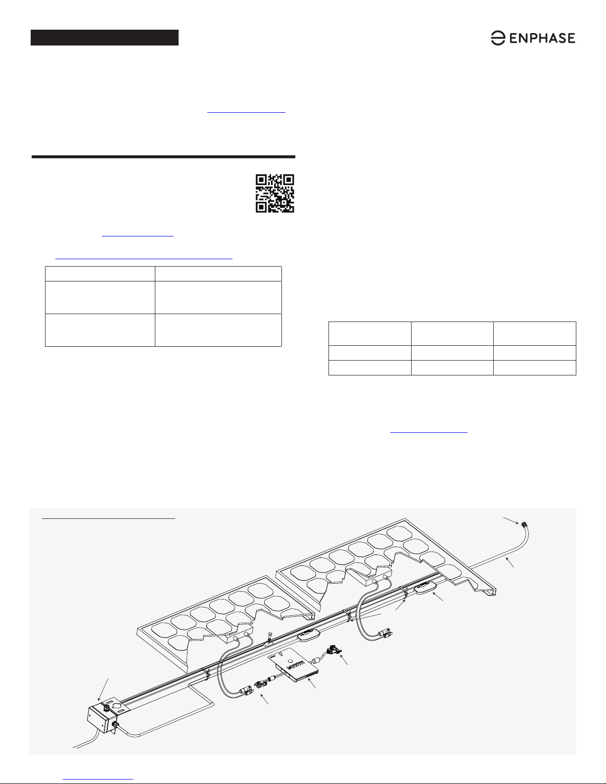
How It Fits Together
AC
junction box
DC
connectors
AC connector
Enphase
Microinverter
Tie wraps or
cable clips
terminator
Engage
Cable
AC drop on
Engage Cable
© Enphase Energy, Inc. All rights reserved.
Page 2
INSTALLATION
1
Position the Enphase Engage Cable
A ) Check the labeling on the Engage Cable drop connectors to be sure that
the cable matches the electrical service at the site. Use 208 VAC Engage
Cable at sites with three-phase 208 VAC service, or use 240 VAC Engage
Cable at sites with 240 VAC single-phase service.
B ) Plan the cable length to allow drop connectors on the Engage Cable to
align with each PV module. Allow extra length for slack, cable turns, and
any obstructions.
C ) Many PV modules have a central stiffening brace. Position the connec-
tors so that they do not conict with the braces.
D ) Cut a length of cable to meet your planned needs.
E ) Lay out the cabling along the installed racking for the AC branch circuit.
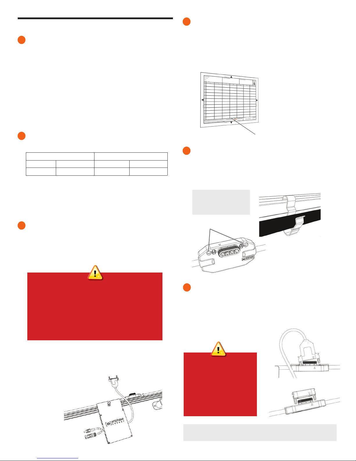
4
Create an Installation Map
Create a paper installation map to record microinverter serial numbers and
position in the array.
A ) Peel the removable serial number label from each microinverter and afx
it to the respective location on the paper installation map.
B ) Peel the label from the Envoy and afx it to the installation map.
C ) Always keep a copy of the installation map for your records.
2
Install an AC Junction Box/Isolator
A ) Verify that AC voltage at the site is within range:
240 VAC Single-Phase 208 VAC Three-Phase
L1 to L2 211 to 264 VAC L1 to L2 to L3 183 to 229 VAC
L1, L2, to N 106 to 132 VAC L1, L2, L3 to N 106 to 132 VAC
B ) Install an appropriately rated, off-the-shelf junction box or isolator at a
suitable location on the racking.
C ) Provide an AC connection from the AC junction box back to the
electricity network connection using equipment and practices as
required by local jurisdictions.
3
Attach the Microinverters to the PV Racking
A ) Mark the approximate centers of each PV module on the PV racking.
B ) Mount the microinverter right side up and under the PV module,
away from rain and sun. Allow a minimum of 1.9 cm (0.75”)
between the roof and the microinverter. Also allow 1.3 cm (0.50”)
between the back of the PV module and the top of the microinverter.
WARNINGS:
• Install the microinverter under the PV module to avoid direct
exposure to rain, UV, and other harmful weather events.
• Do not mount the microinverter upside down or in a vertical
position that allows water to collect in the DC connector recess
as it may have a harmful effect on the long term endurance of
the unit.
• Do not expose the AC or DC connectors (on the Engage
Cable connection, PV module, or the microinverter) to harmful
weather events before the connectors are mated as it may
result in weather rated damage to the connection.
afx serial
number labels
5
Dress the Cable
A ) Use cable clips or tie wraps to attach the cable to the racking.
B ) Dress any excess cabling in loops so that it does not contact the roof.
Do not form loops smaller than 12 cm (4.75 inches) in diameter.
Keep the drop connector
release holes clear and
accessible.
release holes
cable clip
6
Connect the Microinverters
A ) Remove and discard the temporary shipping cap from the cable
connector and connect the microinverter. Listen for two clicks as the
connectors engage.
B ) Cover any unused connectors with Enphase Sealing Caps. Listen for two
clicks as the connectors engage.
C ) Torque the microinverter fasteners as follows. Do not over torque.
Using an impact driver to tighten the mounting hardware is not
recommended due to the risk of thread galling.
•
6 mm (1/4”) mounting hardware: 5 N m (45 to 50 in-lbs)
•
8 mm (5/16”) mounting hardware: 9 N m (80 to 85 in-lbs)
WARNING: Install sealing caps
on all unused AC connectors
as these become live when the
system is energized by the
utility. Sealing caps are required
for protection against moisture
ingress. Do not use shipping
caps to cover unused
connectors.
To remove a sealing cap or AC connector, you must use an Enphase
disconnect tool or a Phillips screwdriver.
Page 3

7
Terminate the Unused End of the Cable
A ) Remove 60 mm of the cable sheath from the conductors.
B ) Check that all the terminator parts are present.
C ) Slide the hex nut onto the cable.
hex
nut
D ) Insert the cable end all the way into the cable organizer (up to the
stop).
E ) Attach the cap.
F ) Attach the terminated cable end to the PV racking with a cable clip or tie
wrap so that the Engage Cable and terminator do not touch the roof.
wire
organizer
cap
bend wires down into
recesses of wire organizer
and trim to length
place cap over
the wire organizer
hold the cap with
the disconnect tool
or a #2 screwdriver
rotate the hex nut with
your hand or a wrench
until the latching
mechanism meets the
base–do not over torque
9
Connect the PV Modules
Mount the PV modules above the microinverters.
DANGER! Electric shock hazard. The DC
conductors of this PV system are ungrounded
A ) Connect the DC leads of each PV mod-
ule to the DC input connectors of the
corresponding microinverter.
B ) Check the LED on the underside of the
microinverter. The LED ashes six times
when DC power is applied.
10
Energize the System
A ) If applicable, turn ON the AC disconnect or circuit breaker for the branch
circuit.
B ) Turn ON the main utility-grid AC circuit breaker. Your system will start
producing power after a ve-minute wait time.
C ) Check the LED on the underside of the microinverter:
LED Indicates
Flashing green Normal operation. AC grid function is normal and there
Flashing orange The AC grid is normal but there is no
Flashing red The AC grid is either not present or not within speci-
Solid red There is an active “DC Resistance Low, Power Off” or
and may be energized.
status
LED
is communication with the Envoy.
communication with the Envoy.
cation.
“GFDI” fault. To reset, refer to the Enphase M250 and
M215 Microinverter Installation and Operation Manual
at: http://www.enphase.com/support.
WARNING: Never unscrew the hex nut. This action
8
Connect to the AC Junction Box/Isolator
Connect the Engage Cable into the AC branch circuit junction box or
isolator. The Engage Cable uses the following wiring color code.
240 VAC Single-Phase Wires 208 VAC Three-Phase Wires
Black – L1
Red – L2
White – Neutral
Green – Ground
The green wire acts as equipment ground (EGC).
can twist and damage the cable.
Black – L1
Red – L2
Blue – L3
White – Neutral
Green – Ground
ACTIVATE MONITORING
After you have installed the microinverters, follow the procedures in the
Enphase Envoy Quick Install Guide to activate system monitoring and
complete the PV installation.
•
Connecting the Envoy
•
Detecting the microinverters
•
Connecting to Enlighten
•
Registering the system
•
Building the virtual array
Page 4

PV Rapid Shutdown Equipment
(PVRSE)
This product is UL Listed as PV Rapid Shut Down
Equipment and conforms with NEC-2014 and NEC2017 section 690.12 and C22.1-2015 Rule 64-218
Rapid Shutdown of PV Systems, for AC and DC
conductors, when installed according to the following
requirements:
• Microinverters and all DC connections must be
installed inside the array boundary. Enphase further
requires that the microinverters and DC connections be installed under the PV module to avoid
direct exposure to rain, UV, and other harmful
weather events.
• The array boundary is dened as 305 mm (1 ft.) from
the array in all directions, or 1 m (3 ft.) form the point
of entry inside a building.
This rapid shutdown system must be provided with an
initiating device and (or with) status indicator which
must be installed in a location accessible to rst
responders, or be connected to an automatic system
which initiates rapid shutdown upon the activation of
a system disconnect or activation of another type of
emergency system.
The initiator shall be listed and identied as a disconnecting means that plainly indicates whether it is in the
“off” or “on” position. Examples are:
• Service disconnecting means
• PV system disconnecting means
• Readily accessible switch or circuit breaker
The handle position of a switch or circuit breaker is
suitable for use as an indicator. Refer to NEC or CSA
C22.1-2015 for more information.
Additionally, in a prominent location near the initiator
device, a placard or label must be provided with a permanent marking including the following wording:
’PHOTOVOLTAIC SYSTEM EQUIPPED WITH RAPID
SHUTDOWN’ The term ‘PHOTOVOLTAIC’ may be
replaced with ‘PV.’
The placard, label, or directory shall be reective, with
all letters capitalized and having a minimum height of
9.5 mm (3/8 in.) in white on red background.
SAFETY
IMPORTANT SAFETY INSTRUCTIONS. SAVE THIS
INFORMATION. This guide contains important instruc-
tions to follow during installation of the Enphase M215 and
M250 Microinverter.
WARNING: Hot surface.
WARNING: Refer to safety instructions.
DANGER: Risk of electric shock.
Refer to manual
Safety Symbols
DANGER! This indicates a hazardous situation,
which if not avoided, will result in death or
+
serious injury.
WARNING! This indicates a situation where
failure to follow instructions may be a safety
*
hazard or cause equipment malfunction. Use extreme caution and follow instructions carefully.
WARNING! This indicates a situation where
failure to follow instructions may result in burn
;
injury.
NOTE: This indicates information particularly
important for optimal system operation.
✓
General Safety
DANGER: Before installing or using the En-
phase Microinverter, read all instructions and
cautionary markings in the technical descrip-
+
tion, on the Enphase Microinverter System, and
on the photovoltaic (PV) equipment.
DANGER: Risk of electric shock. Do not use En-
phase equipment in a manner not specied by
the manufacturer. Doing so may cause death or
+
injury to persons, or damage to equipment.
DANGER: Risk of electric shock. Be aware that
installation of this equipment includes risk of
electric shock. Do not install the AC junction
+
box without rst removing AC power from the
Enphase System.
General Safety, continued
DANGER: Risk of electric shock. The DC
conductors of this photovoltaic system are
ungrounded and may be energized.
+
WARNING: Risk of electric shock. Always de-energize the AC branch circuit before servicing.
Never disconnect the DC connectors under load.
+
WARNING: Risk of electric shock. Risk of
re. Only use electrical system components
approved for wet locations.
+
WARNING: Risk of electric shock. Risk of re.
Only qualied personnel should troubleshoot,
install, or replace Enphase Microinverters or the
+
Engage Cable and Accessories.
WARNING: Risk of electric shock. Risk of re.
Ensure that all AC and DC wiring is correct and
that none of the AC or DC wires are pinched or
+
damaged. Ensure that all AC junction boxes are
properly closed.
WARNING: Risk of electric shock. Risk of re. Do
not exceed the maximum number of microinverters in an AC branch circuit as listed in this
+
guide. You must protect each microinverter AC
branch circuit with a 20A maximum breaker.
WARNING: Do not connect Enphase Microinverters to the grid or energize the AC circuit(s)
until you have completed all of the installation
*
procedures and have received prior approval
from the electrical utility company.
NOTE: To ensure optimal reliability and to meet
warranty requirements, install the Enphase
✓
Microinverters and Engage Cable according to
the instructions in this guide.
NOTE: Perform all electrical installations in
accordance with all applicable local electrical
✓
codes and the National Electrical Code (NEC),
ANSI/NFPA 70.
NOTE: The AC and DC connectors on the cabling
are rated as a disconnect only when used with
✓
an Enphase Microinverter.
NOTE: Protection against lightning and resulting
voltage surge must be in accordance with local
✓
standards.
Microinverter Safety
WARNING: Risk of skin burn. The body of the
Enphase Microinverter is the heat sink. Under
normal operating conditions, the temperature
;
is 20°C above ambient, but under extreme
conditions the microinverter can reach 90°C. To
reduce risk of burns, use caution when working
with microinverters.
WARNING: Risk of electric shock. Risk of re. If
the AC cable on the microinverter is damaged, do
not install the microinverter.
+
WARNING: Risk of electric shock. Risk of re. Do
not attempt to repair the Enphase Microinverter;
it contains no user-serviceable parts. If it fails,
+
contact Enphase customer service to obtain an
RMA (return merchandise authorization) number
and start the replacement process. Tampering
with or opening the Enphase Microinverter will
void the warranty.
WARNING: Risk of re. The DC conductors of the
PV module must be labelled “PV Wire” or “PV Cable” when paired with the Enphase Microinverter.
+
WARNING: Risk of equipment damage. Install the
microinverter under the PV module to avoid direct
exposure to rain, UV, and other harmful weather
*
events. Do not mount the microinverter upside
down or in a vertical position that allows water to
collect in the DC connector recess as it may have
a harmful effect on the long term endurance of
the unit. Do not expose the AC or DC connectors
(on the Engage Cable connection, PV module,
or the microinverter) to harmful weather events
before the connectors are mated as it may result
in weather rated damage to the connection.
WARNING: Risk of equipment damage. The Enphase Microinverter is not protected from damage
due to moisture trapped in cabling systems. Never
*
mate microinverters to cables that have been left
disconnected and exposed to wet conditions. This
voids the Enphase warranty.
WARNING: You must match the DC operating
voltage range of the PV module with the
allowable input voltage range of the Enphase
*
Microinverter.
WARNING: The maximum open circuit voltage
of the PV module must not exceed the specied
maximum input DC voltage of the Enphase
*
Microinverter.
Microinverter Safety, continued
WARNING: Risk of equipment damage. The
Enphase Microinverter functions only with a
standard, compatible PV module with appro-
*
priate ll-factor, voltage, and current ratings.
Unsupported devices include smart PV modules,
fuel cells, wind or water turbines, DC generators,
and non-Enphase batteries, etc. These devices
do not behave like standard PV modules, so
operation and compliance is not guaranteed.
These devices may also damage the Enphase
Microinverter by exceeding its electrical rating,
making the system potentially unsafe.
WARNING: Risk of electric shock. Risk of re.
Only qualied personnel may connect the
Enphase Microinverter to the utility grid.
+
NOTE: The Enphase Microinverter has eld-adjust-
able voltage and frequency trip points that may
✓
need to be set, depending upon local requirements. Only an authorized installer with the permission and following requirements of the local
electrical authorities should make adjustments.
Engage Cable and Accessory Safety
DANGER: Risk of electric shock. Do not install
the Engage Cable terminator cap while power is
+
connected.
WARNING: Risk of electric shock. Risk of re.
When stripping the sheath from the Engage
Cable, make sure the conductors are not dam-
+
aged. If the exposed wires are damaged, the
system may not function properly.
WARNING: Risk of electric shock. Risk of re.
Do not leave AC connectors on the Engage
Cable uncovered for an extended period. If you
+
do not replace the microinverter immediately,
you must cover any unused connector with a
sealing cap. Do not reuse sealing caps.
WARNING: Risk of electric shock. Risk of re.
Make sure protective sealing caps have been
installed on all unused AC connectors. Unused
+
AC connectors are live when the system is
energized. Do not reuse sealing caps.
WARNING: Use the terminator only once. If
you open the terminator after installation,
the latching mechanism is destroyed. If the
*
latching mechanism is defective, do not use the
terminator. Do not circumvent or manipulate the
latching mechanism.
WARNING: When installing the Engage Cable,
secure any loose cable to minimize tripping
hazard
*
NOTE: There are two release-holes in the drop
connector on the cable. These are not for mount-
✓
ing but are used to disconnect the connector.
Keep these release holes clear and accessible.
NOTE: When looping the Engage Cable, do not
form loops smaller than 4.75 inches (12 cm) in
✓
diameter.
NOTE: If you need to remove a sealing cap, you
must use the Enphase disconnect tool or a #3
✓
Phillips screwdriver. Do not reuse sealing caps.
NOTE: When installing the Engage Cable and
accessories, adhere to the following:
✓
• Do not expose the terminator cap or cable connections to directed, pressurized liquid (water
jets, etc.).
• Do not expose the terminator cap or cable
connections to continuous immersion.
• Do not expose the terminator cap or cable
connections to continuous tension (e.g., tension
due to pulling or bending the cable near the
connection).
• Use only the connectors and cables provided.
• Do not allow contamination or debris in the
connectors.
• Use the terminator cap and cable connections
only when all parts are present and intact.
• Do not install or use in potentially explosive
environments.
• Do not allow the terminator to come into con-
tact with open ame.
• Make sure that all terminator cap seals are
seated correctly in the wire organizer.
• Fit the terminator cap using only the prescribed
tools and in the prescribed manner.
• Use the terminator to seal the conductor end of
the Engage Cable; no other method is allowed.
NOTE: Do not use the shipping cap to cover
unused connectors. The shipping cap does
✓
not provide an adequate environmental seal.
Enphase sealing caps are required to protect
against moisture ingress.
Enphase Customer Support: enphase.com/en-us/support/contact
Page 5

N S E W
N S E O
Installer/Instalador:Customer/Cliente:
To Sheet / A la hoja de: ________
Número de serie de Envoy
Envoy Serial Number Label /
To Sheet / A la hoja de: ________
1 2 3 4 5 6 7
Panel Group/Grupo de los paneles:
Azimuth/Azimut:
Tilt/Inclinación:
Sheet/Hoja _____ of/de _____
A
To Sheet / A la hoja de: ________
B
C
D
E
F
G
H
J
K
To Sheet / A la hoja de: ________
L
M
Scan completed map and upload it to Enphase. Click “Add a New System”
at https://enlighten.enphaseenergy.com. Use this map to build the virtual array in Enlighten’s Array Builder. /
Escanee el mapa completo y cárguelo en Enphase. Haga clic en “Añadir nuevo sistema”
en https://enlighten.enphaseenergy.com. Utilice este mapa para crear el conjunto de paneles
virtual en el Creador de conjuntos de paneles de Enlighten.
 Loading...