

Page 1
Troubleshooting an Enphase System
1
Installer’s Guide to Troubleshooting
an Enphase System
2014 Enphase Energy Inc. August 2014
Page 2

Troubleshooting an Enphase System
2
Contact Information
Enphase Energy Inc.
1420 N. McDowell Blvd.
Petaluma, CA 94954
http://www.enphase.com
info@enphaseenergy.com
support@enphaseenergy.com
FCC Compliance
This equipment has been tested and found to comply with the limits for a Class B digital device, pursuant
to part 15 of the FCC Rules. These limits are designed to provide reasonable protection against harmful
interference in a residential installation. This equipment generates, uses and can radiate radio frequency
energy and, if not installed and used in accordance with the instructions, may cause harmful interference
to radio communications. However, there is no guarantee that interference will not occur in a particular
installation. If this equipment does cause harmful interference to radio or television reception, which can
be determined by turning the equipment off and on, you are encouraged to try to correct the interference
by one or more of the following measures:
Reorient or relocate the receiving antenna.
Increase the separation between the equipment and the receiver.
Connect the equipment into an outlet on a circuit different from that to which the receiver is
connected.
Consult the dealer or an experienced radio/TV technician for help.
Changes or modifications not expressly approved by the party responsible for compliance may void the
user’s authority to operate the equipment.
Other Information
Product information is subject to change without notice. All trademarks are recognized as the property of
their respective owners.
User documentation is updated frequently; Check the Enphase website
(
http://www.enphase.com/support) for the latest information.
For warranty text, refer to
For Enphase patent information, refer to http://enphase.com/company/patents/.
© 2014 Enphase Energy Inc. All rights reserved.
http://www.enphase.com/warranty.
2014 Enphase Energy Inc. August 2014
Page 3

Troubleshooting an Enphase System
3
Table of Contents
Important Safety Information ......................................................................................................................... 5
Read this First .................................................................................................................................. 5
Product Labels ................................................................................................................................. 5
Safety and Advisory Symbols .......................................................................................................... 5
Safety Instructions ............................................................................................................................ 5
General Safety ............................................................................................................................................. 5
Microinverter Safety ..................................................................................................................................... 6
Engage Cable and Accessory Safety .......................................................................................................... 7
Overview ....................................................................................................................................................... 8
Troubleshooting Topics ................................................................................................................................. 9
Envoy and Communications Issues ............................................................................................................ 11
Envoy Issues .................................................................................................................................. 11
A physical Ethernet connection is not practical at the site ......................................................................... 11
LCD is completely blank ............................................................................................................................ 12
LCD displays “Reset Clock” ....................................................................................................................... 12
LCD displays “Envoy Failure” .................................................................................................................... 12
LCD displays "Scanning Inhibited" ............................................................................................................ 12
Networking and Internet Issues ..................................................................................................... 13
Issue: Wireless Adapter Wi-Fi Problems ................................................................................................... 13
Issue: How Set Up Wi-Fi without Wi-Fi WPS ............................................................................................. 13
LCD shows a non-routable/self-assigned IP address AND shows “-Web” ................................................ 15
The Envoy is using a static IP and cannot get a web connection .............................................................. 17
LCD periodically shows “-Web” for minutes or hours at a time. ................................................................. 17
LCD shows a valid IP, but also shows “-Web” ........................................................................................... 17
The router or DSL modem at the site has only one Ethernet port .............................................................. 17
Internet service is not available on site ...................................................................................................... 18
Are my power line communication bridges working? ................................................................................. 19
Issue: Internet Traffic is Slower After Installing a Bridge ........................................................................... 19
Asoka PL9650 ....................................................................................................................................... 19
Asoka PL9660-Q1 ................................................................................................................................. 19
ReadyNet EN200 .................................................................................................................................. 19
Tenda P200 .......................................................................................................................................... 20
The Envoy cannot get a “+Web” even though all premises networking is intact ........................................ 20
Can I use a dial-up Internet connection with the Envoy? ........................................................................... 20
Power Line Communication Issues between the Envoy & Microinverters ..................................... 21
Microinverters are not detected, or, power line communication level is low or poor .................................. 22
How to identify an interfering load ............................................................................................................. 24
The Envoy is in a circuit on the primary load center, the solar circuits are on a downstream subpanel .... 24
Power line communications with a Line-side Tap (or Supply-Side, or PLC) Installation ............................ 25
Multiple Envoys and Filtering ..................................................................................................................... 25
Using a Transformer to Isolate Communication Domains ......................................................................... 25
Using an Aftermarket Filter to Isolate Communication Domains................................................................ 26
How to Get Training on Enphase Power Line Communication .................................................................. 26
2014 Enphase Energy Inc. August 2014
Page 4

Troubleshooting an Enphase System
4
Microinverter and PV Module Issues .......................................................................................................... 27
Microinverter LEDs ......................................................................................................................... 27
Startup LED Operation .............................................................................................................................. 27
Post-Startup LED Indications..................................................................................................................... 27
The Microinverter LEDs are flashing red ................................................................................................... 28
The Microinverter LEDs are flashing orange ............................................................................................. 28
The Microinverter LEDs are not lit ............................................................................................................. 28
Power Production ........................................................................................................................... 28
The unit under review shows low production. ............................................................................................ 28
One unit shows 0W of production but adjacent units are productive ......................................................... 29
About Open-Circuit Voltage ....................................................................................................................... 30
Other Checks............................................................................................................................................. 30
The PV modules are dark and no production displays in Enlighten ........................................................... 31
Enlighten does not allow me to select the PV module ............................................................................... 31
View the PV module production history ..................................................................................................... 31
Run a report to view production history ..................................................................................................... 31
View module production history ................................................................................................................. 32
There is an event or alert message on the system .................................................................................... 32
Messages and Alerts ................................................................................................................................... 33
ACFOOR (AC Frequency Out of Range) ....................................................................................... 33
ACVOOR (AC Voltage Out of Range) ........................................................................................... 34
ACVOOR in an entire branch or multiple branches ................................................................................... 34
ACVOOR in only a few microinverters ....................................................................................................... 36
Critical Temperature ....................................................................................................................... 37
DC Resistance Low – Power Off ................................................................................................... 37
DC Too Low ................................................................................................................................... 39
DC Too High .................................................................................................................................. 40
Device Produced No Power ........................................................................................................... 40
Envoy not Reporting ....................................................................................................................... 40
Gateway Failure ............................................................................................................................. 40
GFI Tripped .................................................................................................................................... 41
Grid Gone ....................................................................................................................................... 42
Microinverter Failed to Report ........................................................................................................ 43
Over Temperature .......................................................................................................................... 43
Zigbee Device Failed to Report ..................................................................................................... 43
Zigbee USB Stick Removed .......................................................................................................... 43
Best Practices ............................................................................................................................................. 44
Installation sequence ..................................................................................................................... 44
Care of the solar array ................................................................................................................... 44
How do I clean the solar array? ................................................................................................................. 44
How do I maintain the solar array? ............................................................................................................ 44
Will a grid-tied solar array provide power during a power outage? ............................................................ 44
Will the array provide power during when it is snowing or hailing? ............................................................ 45
Can I add solar panels to the solar power system later? ........................................................................... 45
Other Questions? ...................................................................................................................................... 45
2014 Enphase Energy Inc. August 2014
Page 5
Troubleshooting an Enphase System
5
Important Safety Information
Read this First
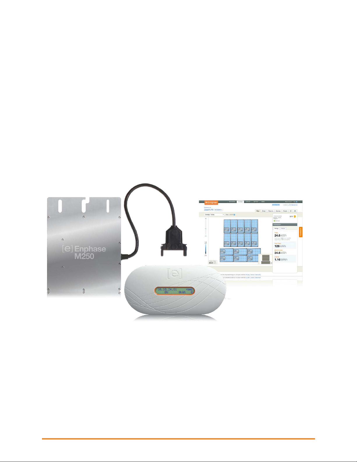
This manual contains important instructions for installers to use during installation and maintenance of the Enphase®
Microinverter System™.
Product Labels
The following symbols appear on the product label and are described here:
WARNING: Hot surface.
DANGER: Risk of electrical shock.
Refer to product instructions.
Safety and Advisory Symbols
To reduce the risk of electric shock, and to ensure the safe installation and operation of the Enphase® Microinverter,
the following safety symbols appear throughout this document to indicate dangerous conditions and important safety
instructions.
DANGER! This indicates a hazardous situation, which if not avoided, will result in death or serious
injury.
WARNING! This indicates a situation where failure to follow instructions may be a safety hazard or
cause equipment malfunction. Use extreme caution and follow instructions carefully.
WARNING! This indicates a situation where failure to follow instructions may result in burn injury.
NOTE: This indicates information particularly important for optimal system operation. Follow
instructions closely.
Safety Instructions
General Safety
CAUTION: Before installing or using the Enphase Microinverter, read all instructions and
cautionary markings in the technical description, on the Enphase Microinverter System, and on the
photovoltaic (PV) equipment.
DANGER: Risk of electric shock. Do not use Enphase equipment in a manner not specified by the
manufacturer. Doing so may cause death or injury to persons, or damage to equipment.
DANGER: Risk of electric shock. Be aware that installation of this equipment includes risk of
electric shock. Do not install the AC junction box without first removing AC power from the Enphase
System.
DANGER: Risk of electric shock. The DC conductors of this photovoltaic system are ungrounded
and may be energized.
WARNING: Risk of electric shock. Always de-energize the AC branch circuit before servicing.
Never disconnect the DC connectors under load.
2014 Enphase Energy Inc. August 2014
Page 6
Troubleshooting an Enphase System
6
WARNING: Risk of electric shock. Risk of fire. Only use electrical system components approved for
wet locations.
WARNING: Risk of electric shock. Risk of fire. Only qualified personnel should troubleshoot, install,
or replace Enphase Microinverters or the Engage Cable and Accessories.
WARNING: Risk of electric shock. Risk of fire. Ensure that all AC and DC wiring is correct and that
none of the AC or DC wires are pinched or damaged. Ensure that all AC junction boxes are
properly closed.
WARNING: Risk of electric shock. Risk of fire. Do not exceed the maximum number of
microinverters in an AC branch circuit as listed in the manual. You must protect each microinverter
AC branch circuit with a 20A maximum breaker.
WARNING: Do not connect Enphase Microinverters to the grid or energize the AC circuit(s) until
you have completed all of the installation procedures and have received prior approval from the
electrical utility company.
NOTE: To ensure optimal reliability and to meet warranty requirements, the Enphase Microinverter
System must be installed according to the instructions in this manual.
NOTE: The AC and DC connectors on the cabling are rated as a disconnect only when used with
an Enphase Microinverter.
NOTE: Protection against lightning and resulting voltage surge must be in accordance with local
standards.
NOTE: Many PV modules have a central stiffening brace. In these cases, do not position the
connector and microinverter at the exact centre of the PV module. Instead, position the drop
connectors so that the connectors do not conflict with the braces.
NOTE: Completely install all microinverters and all system AC connections prior to installing the PV
modules.
Microinverter Safety
WARNING: Risk of Skin Burn. The body of the Enphase Microinverter is the heat sink. Under
normal operating conditions, the temperature is 15°C above ambient, but under extreme conditions
the microinverter can reach a temperature of 80°C. To reduce risk of burns, use caution when
working with microinverters.
WARNING: Risk of electric shock. Risk of fire. If the AC cable on the microinverter is damaged, do
not install the unit.
WARNING: Risk of electric shock. Risk of fire. Do not attempt to repair the Enphase Microinverter;
it contains no user-serviceable parts. If it fails, contact Enphase customer service to obtain an RMA
(return merchandise authorization) number and start the replacement process. Tampering with or
opening the Enphase Microinverter will void the warranty.
WARNING: Risk of Equipment Damage. The M215 and M250 may be paired only with 60-cell PV
modules.
WARNING: When pairing with M250 (M250-60-2LL-S22, S23, or S24) or M215 (M215-60-2LL-S22IG, S23-IG, or S24-IG), the PV module DC conductors must be labeled “PV Wire” or “PV Cable”.
WARNING: Risk of Equipment Damage. You must match the DC operating voltage range of the PV
module with the allowable input voltage range of the Enphase Microinverter.
WARNING: Risk of Equipment Damage. The maximum open circuit voltage of the PV module must
not exceed the specified maximum input DC voltage of the Enphase Microinverter.
WARNING: Risk of Equipment Damage. The microinverter must be installed under the module, out
of rain and sun. Do not mount the microinverter in a position that allows long-term exposure to
direct sunlight or in a vertical orientation that allows water to collect in the DC connector recess. Do
not install the microinverter black side up or vertically, with the DC connectors facing up.
WARNING: Be aware that only qualified personnel may connect the Enphase Microinverter to the
utility grid.
2014 Enphase Energy Inc. August 2014
Page 7
7
NOTE: The Enphase Microinverters has field-adjustable voltage and frequency trip points that may
need to be set, depending upon local requirements. Only an authorized installer with permission
and following the requirements of the local electrical authorities should make adjustments.
NOTE: The Enphase Microinverter works with single-phase or three-phase electrical service.
Engage Cable and Accessory Safety
DANGER: Risk of electric shock. The Engage Cable terminator cap must not be installed while
power is connected.
WARNING: Risk of electric shock. Risk of fire. When stripping the sheath from the Engage Cable,
make sure the conductors are not damaged. If the exposed wires are damaged, the system may
not function properly.
WARNING: Risk of electric shock. Risk of fire. Do not leave AC connectors on the Engage Cable
uncovered for an extended period. If you do not replace the microinverter immediately, you must
cover any unused connector with a sealing cap. Sealing caps may not be reused.
WARNING: Risk of electric shock. Risk of fire. Make sure protective sealing caps have been
installed on all unused AC connectors. Unused AC connectors are live when the system is
energized by the grid. Sealing caps may not be reused.
WARNING: Use the terminator only once. If you open the terminator following installation, the
latching mechanism is destroyed. Do not reuse the terminator. Do not circumvent or manipulate the
latching mechanism.
CAUTION: When installing the Engage Cable, secure any loose cable to minimize tripping hazard.
NOTE: Check the labeling on the Engage Cable drop connectors to be sure that the cable matches
the electrical utility service at the site. Use 208 VAC Engage Cable at sites with three-phase
service, or use 240 VAC Engage Cable at sites with single-phase service.
NOTE: There are two release-holes in the drop connector on the cable. These are not for mounting
but are used to disconnect the connector. Keep these release holes clear and accessible.
NOTE: When looping the Engage Cable, do not form loops smaller than 4.75 in. (12 cm) in
diameter.
NOTE: If you need to remove a sealing cap, you must use the Enphase disconnect tool or a
screwdriver. Sealing caps may not be reused.
NOTE: When installing the Engage Cable and accessories, adhere to the following:
Do not expose the terminator cap or cable connections to directed, pressurized liquid (water
jets, etc.).
Do not expose the terminator cap or cable connections to continuous immersion.
Do not expose the terminator cap or cable connections to continuous tension (e.g., tension
due to pulling or bending the cable near the connection).
Use only the connectors and cables provided.
Do not allow contamination or debris in the connectors.
Use the terminator cap and cable connections only when all parts are present and intact.
Do not install or use in potentially explosive environments.
Do not allow the terminator to come into contact with open flame.
Make sure that all terminator cap seals are seated correctly in the wire organizer.
Fit the terminator cap using only the prescribed tools and in the prescribed manner.
Use the terminator to seal the conductor end of the Engage Cable; no other method is
allowed.
NOTE: Do not use the shipping cap to cover unused connectors. The shipping cap does not
provide an adequate environmental seal. Enphase sealing caps are required to protect against
moisture ingress.
Troubleshooting an Enphase System
2014 Enphase Energy Inc. August 2014
Page 8
Troubleshooting an Enphase System
8
Overview
This document describes troubleshooting flows and procedures only. For product and installation
information, refer to
Troubleshooting areas covered in this document include:
Envoy and Communications Issues
Microinverter / PV Module Issues
Messages and Alerts
Best Practices
Use the troubleshooting table on page 9 to find information on a problem according to category:
Production issues
Envoy not reporting
Microinverter not reporting
General troubleshooting
http://www.enphase.com/support.
2014 Enphase Energy Inc. August 2014
Page 9

9
Troubleshooting Topics
Topic
Page
Production issues
ACFOOR (AC Frequency Out of Range)
33
ACVOOR (AC Voltage Out of Range)
34
When an entire branch or multiple branches are impacted
34
When only a few microinverters are impacted
36
Critical Temperature
37
DC Too Low
39
DC Too High
40
Device Produced No Power
40
GFI tripped
41
DC Resistance Low – Power Off
37
Grid Gone
42
Over Temperature
43
The unit under review shows low production.
28
Why is one unit showing 0W production when adjacent units are productive?
29
Notes on Open Circuit Voltage
30
Other Things to Check
30
Envoy not reporting
Envoy not Reporting
40
Gateway Failure
40
LCD displays “Envoy Failure”
12
LCD periodically shows “-Web” for minutes or hours at a time.
17
LCD shows a good IP, but also shows “-Web”
17
LCD shows a non-routable/self-assigned IP address and also shows “-Web”
15
The Envoy cannot get a “+Web” even though all premises networking is intact
20
The Envoy is using a static IP and cannot get a web connection
17
Microinverter not reporting
Microinverters are not detected / Power line communication level is low/poor
22
Microinverter Failed to Report
43
My panels are dark in Enlighten and no production value is displayed
31
General
A physical Ethernet connection is not practical at this site
11
Are my power line communication bridges working?
19
Can I use a dial-up Internet connection with the Envoy?
20
Enlighten will not allow me to select the panel
31
Use the following table to find information on a problem by category.
Troubleshooting an Enphase System
2014 Enphase Energy Inc. August 2014
Page 10

Troubleshooting an Enphase System
10
Topic
Page
How to get further training on Enphase power line communication
26
How to identify an interfering load
24
I would like to see my panel’s production history
31
Internet service is not available on site
18
LCD displays "Scanning Inhibited"
12
LCD displays “Reset Clock”
12
LCD is completely blank
12
Run a report to view production history
31
The DSL modem at the site has only one Ethernet port, and it is being used
17
The Envoy is in a circuit on the primary load-center, the solar circuits are on a
downstream subpanel
24
The Envoy is slowing down other Internet traffic
19
The Microinverter LEDs are flashing orange
28
The Microinverter LEDs are flashing red
28
The Microinverter LEDs are not lit
28
There is an event or alert message on the system
32
This is a Line-side Tap (or Supply-Side, or PLC) Installation
25
Use the Graph widget to view production history
32
When do I need an additional Envoy?
25
Zigbee Device Failed to Report
43
Zigbee USB Stick Removed
43
Best Practices
Installation sequence
44
Care of the solar array
44
2014 Enphase Energy Inc. August 2014
Page 11
11
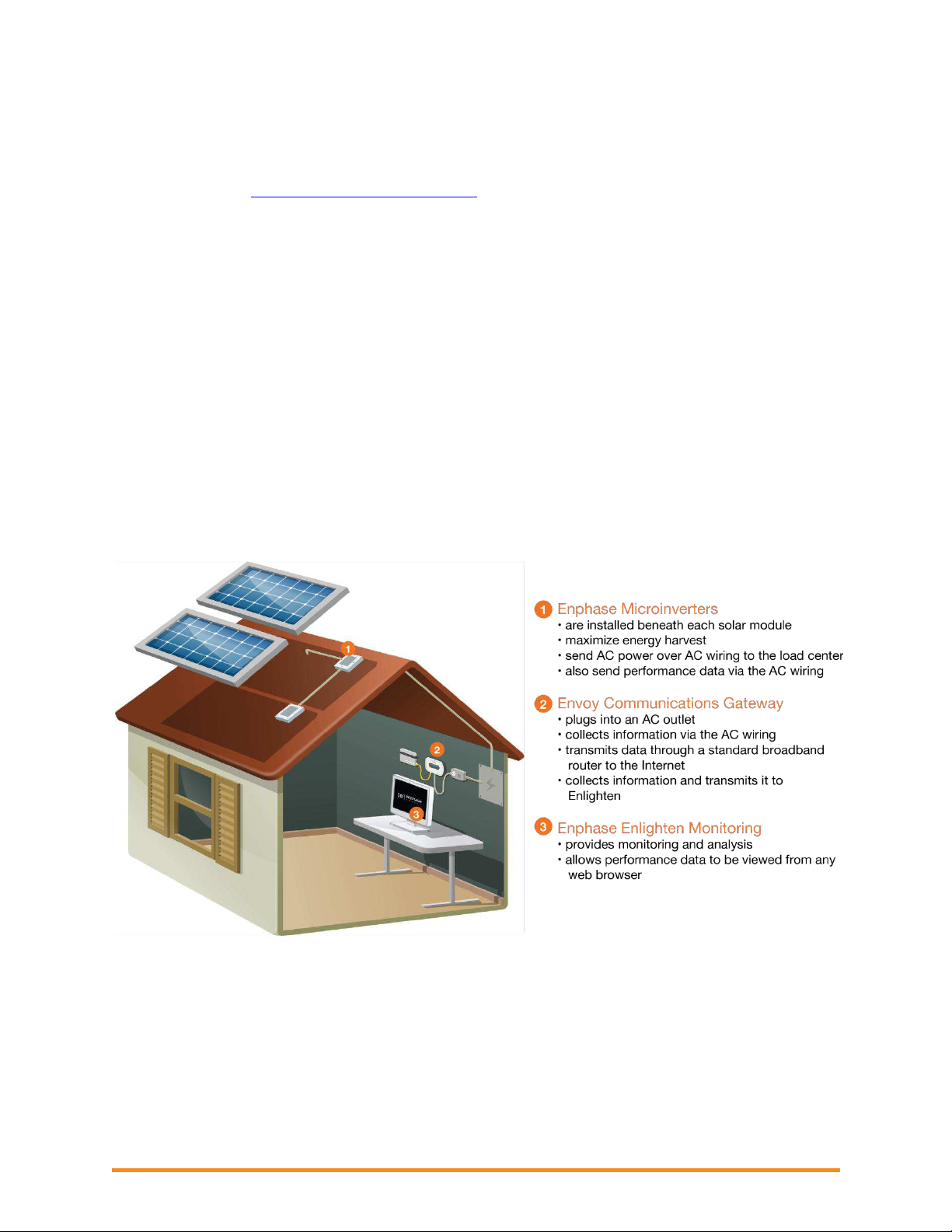
Envoy and Communications Issues
Broadband
Router
Envoy
Power line
communication
bridges
Wireless
Router
Envoy
Wireless
Adapter
The following sections describe possible problems and
solutions. Areas include:
Troubleshooting an Enphase System
Envoy Issues
Networking and Internet Issues
Power Line Communication Issues between
the Envoy & Microinverters
WARNING: Do not attempt to repair the
Enphase Envoy; it contains no userserviceable parts. Tampering with or
opening the Envoy will void the warranty. If
the Envoy fails, contact Enphase customer
service to obtain an RMA (return
merchandise authorization) number and
start the replacement process.
Envoy Issues
A physical Ethernet connection is not practical at the site
The location for the Envoy yields a good signalstrength between the Envoy and the Microinverters
(over the power lines), but it is remote from the
router. An Ethernet cable from the broadband router
to this spot is not practical.
Try these solutions:
Use an Enphase Wireless Adapter (order
WF-01) as shown.
Use Enphase power line communication
bridges (order ELPC-01) with the Envoy as
shown.
Or, you can use a third-party wireless
Ethernet bridge (available at computer
stores).
2014 Enphase Energy Inc. August 2014
Page 12

Troubleshooting an Enphase System
12
LCD is completely blank
1. Try another outlet (just in case).
2. If this fails, the Envoy unit must be replaced. There are no field replaceable parts for the Envoy.
Contact Enphase Customer Support support@enphaseenergy.com.
LCD displays “Reset Clock”
If the Envoy has a current Internet connection, let it use this connection to retrieve an upgrade from
Enlighten. This may take up to 20 minutes, depending upon the speed of the connection. You may need
to contact Enphase Customer Support to initiate the upgrade.
LCD displays “Envoy Failure”
This message displays after the Envoy has tried unsuccessfully three times to initialize. This may happen
when the Envoy has been moved, and its initialization process interrupted.
1. Unplug the Envoy from the electrical outlet, and then plug it in again. Leave the Envoy in place for
at least 15 minutes.
2. If it continues to display Envoy Failure or if it never moves beyond the Initialization stage, contact
Enphase Customer Support.
LCD displays "Scanning Inhibited"
This message displays after an installer has used the Installer's Toolkit to provision the Envoy. Leave the
Envoy in this condition for normal operation. If you need to re-enable scanning, contact Enphase
Customer Support (support@enphaseenergy.com).
2014 Enphase Energy Inc. August 2014
Page 13

Troubleshooting an Enphase System
13
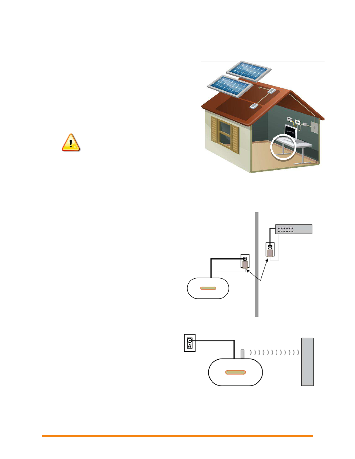
Networking and Internet Issues
The Enphase Envoy Communications Gateway operates much as another computer does. As such,
many of the troubleshooting steps for the Envoy are the same as those for other computers at the site.
Issue: Wireless Adapter Wi-Fi Problems
If the wireless installation fails, try these solutions:
Verify that the Envoy is at version "R3.8" or later. If needed, upgrade the Envoy as directed.
Verify that the wireless adapter is fully seated in the Envoy USB port.
Verify that the Envoy has two USB ports and that the USB adapter is in the left port (looking
at Envoy from the front). Envoys with only one USB port do not support Wi-Fi.
Remove power from all units in the chain, then apply power in this order: 1) modem, 2)
router, and 3) Envoy.
If the Envoy is installed in an enclosure and you are using the wireless adapter, that enclosure
must be plastic or fiberglass to allow wireless communication. Metal enclosures impede wireless
communication.
Stucco and plaster wall construction may contain metal mesh, which can affect wireless range. If
you cannot see your router or access point in the list on the Envoy, or cannot maintain a
connection, relocate the Envoy to be closer to your router or access point.
If you remove the wireless adapter, wait about 15 seconds before re-inserting it.
Issue: How Set Up Wi-Fi without Wi-Fi WPS
The Envoy with wireless adapter supports several wireless security protocols:
Wi-Fi WPS
WEP Open System
WEP Shared Key
WPA-PSK
WPA2-PSK
WPA-EAP
WPA2-EAP
If the router does not support Wi-Fi WPS or you do not wish to use Wi-Fi WPS, follow these steps to
establish a wireless connection using one of the listed protocols.
a. Verify that the wireless adapter is fully seated in the left USB port (looking at Envoy from the
front). Envoys with only one USB port do not support Wi-Fi.
b. Plug the included Ethernet cable either to a laptop directly or to a PC on the same broadband
router network.
c. Access the Envoy Administration page. Enter the IP address of the Envoy LCD in the Internet
browser.
d. Enter the default login credentials for the Administration menu:
Username: admin
2014 Enphase Energy Inc. August 2014
Page 14
Troubleshooting an Enphase System
14
Password: admin
e. From the Administration menu, select Wi-Fi Configuration. This menu option is available only
when the wireless adapter is installed in a USB port on the Envoy.
f. The interface displays a list of available networks.
g. Click a network to select it and enter the password.
If you don’t see your network listed, the router
SSID broadcast may be blocked. If so, enter the
SSID (name) and password.
If your network is not blocked and not listed, click
Re-Scan to refresh the list of networks.
Status messages appear during the connection
process, including “Connection Test” and
Confirmation”.
h. Click Join Network when displayed.
After joining, the network displays in bold in the list of
available networks.
i. Disconnect the Ethernet cable.
Within two minutes, an updated IP address displays
on the Envoy LCD screen, indicating that a wireless
connection is established.
Within a minute, the Envoy LCD screen displays
+Web, indicating a successful connection to
Enphase.
2014 Enphase Energy Inc. August 2014
Page 15

Troubleshooting an Enphase System
15
What is DHCP?
During the power-up sequence, the Envoy requests a DHCP-issued IP address from the
broadband router. The router obtains an address from a pool of available IP addresses from a
Dynamic Host Configuration Protocol (DHCP) server. The DHCP server ‘leases’ an IP address to
each device in the Local Area Network (LAN). The Envoy, like other computers in the LAN, uses
the DHCP IP address as the path to the Internet.
LCD shows a non-routable/self-assigned IP address AND shows “-Web”
The Envoy has no connection to the Enlighten software platform. If the Envoy shows a self-assigned IP
(169.254.120.1) and “-Web”, either a physical Ethernet connectivity issue is preventing it from obtaining a
DHCP-issued IP address, or there is a setup problem.
Troubleshoot as follows.
1. Verify the Envoy connection to the router.
a. Verify connection. The Envoy requires connection to a router, with the CAT5 cable that came
with the Envoy or by installing an Enphase Wireless Adapter (order WF-01 separately).
b. Verify that the Envoy is connected to a broadband router. A switch or hub cannot be
substituted for the router.
i. Determine the make and model of the router. This will help you discover if it is a true
router, rather than a hub or switch.
ii. A switch or hub placed between the modem and the ISP connection may also cause
this problem.
c. Check that the Local Area Network (LAN) port LED is lit. The LED is on the rear of Envoy
next to the LAN port., is the Envoy network port light lit? If so, the Envoy is waiting for a
response from Enlighten, and will show “+Web” soon. If not, reseat connections or try another
CAT5 cable.
2. Did the Envoy previously have an Internet connection at this site?
a. If so, what has changed? Is it a new router or ISP? Was there a power outage?
b. If yes to any of these, remove power from all units in the chain, then apply power again in this
order: Cable/DSL Modem, Router, and Envoy.
c. If the router was replaced,
make sure the new device
is actually a router, not a
hub or a switch.
d. Look up the site in
Enlighten. According to
the graph, when did this
Envoy last report (last
date/time shown in the
energy production graph)?
What changed at that
point in time?
e. Try using the Envoy menu
button to “Get New IP
address.” Press and hold
2014 Enphase Energy Inc. August 2014
Page 16

Troubleshooting an Enphase System
16
Direction
Source
Protocol
Port
Destination
OUT
<Envoy IP address>
TCP
443
reports.enphaseenergy.com
OUT
<Envoy IP address>
TCP
443
securereports.enphaseenergy.com
OUT
<Envoy IP address>
TCP
443
home.enphaseenergy.com
OUT
<Envoy IP address>
TCP
2020
home.enphaseenergy.com †
OUT
<Envoy IP address>
UDP
123
us.pool.ntp.org
† Port 2020 is an optional support port used when there are issues with the standard HTTPS port (443).
What is a Firewall?
A network firewall is a set of router rules that allow or disallow certain types of inbound or
outbound traffic to your LAN. Firewall rules are specific rules that you can set up to allow or
disallow different types of network traffic.
What is a MAC address?
A MAC address is a unique identifier permanently assigned to a network interface and MAC
filtering uses those addresses as a common security technique. In the router, enter a list of MAC
addresses from the other computers at your site that share the router. Only those MAC addresses
can participate in the router’s network.
the Envoy Menu button; after two seconds you will see the Envoy menu. Continue holding the
Menu button; when the LCD window displays “Get New IP Address”, release the Menu
button.
f. If using an Ethernet CAT5 cable between the Envoy and router, try replacing this cable.
g. Is there an “Envoy not Reporting” event in Enlighten? If so, see page 40.
3. If Enphase power line communication bridges are in use, check that all LEDs are either on or flashing as
described in “Are my power line communication bridges working?” Try the following:
a. Relocate one of the bridges to a different power outlet, and make sure that neither one is in a
power-strip or UPS battery-backup device.
b. Bypass the bridges and plug the Envoy directly into the Router to eliminate the bridges as the
source of trouble. They may be faulty or they may be too far apart.
c. Replace the Ethernet cables, one at a time, to eliminate these as the cause.
4. Is the router set up with MAC (media access control) filtering? If enabled, MAC filtering prevents the
Envoy from obtaining a DHCP address because the router refuses the DHCP request.
Temporarily disable MAC filtering, add the MAC address of the Envoy to the broadband filter
MAC address list, and then enable MAC filtering.
5. Is there a firewall set up on the LAN? Most routers either have the firewall disabled or they come with
a basic firewall rule of Allow all outbound traffic but disallow all inbound traffic. This allows you to view
any website, but prevents unsolicited Internet traffic from coming into the premises via the router.
The Envoy initiates outbound connections to Internet servers. Such connections may be restricted
by firewall rules set up on the site’s broadband router. Broadband routers typically allow all outbound
connections and restrict any or all inbound connections.
If outbound firewall rules are applied at the site, you must configure a static IP address for the
Envoy and add new rules that allow outbound access as follows:
2014 Enphase Energy Inc. August 2014
Page 17

Troubleshooting an Enphase System
17
The Envoy connects to these servers using their DNS names. If you add firewall rules for Envoy
reporting, Enphase recommends using the DNS names rather than the underlying IP addresses as
the IP addresses are subject to change without notice.
WARNING: Do not change the Envoy DHCP setting to use a static IP address unless you
also reserve the same IP address on the broadband router. See the section on DHCP
Reservations in your router's setup manual. Failure to reserve the static IP address on the
router results in duplicate IP addresses and intermittent Internet connection problems with the
Envoy.
The Envoy is using a static IP and cannot get a web connection
If the site owner prefers not to use DHCP, set up the Envoy to use a static IP address.
Use the Envoy’s web interface to navigate to the Administration page. The Username is “admin”,
and password is “admin”. Click the “Network Connectivity” menu item. This allows you to see if
the Envoy is using DHCP or static IP, and allows you to change this setting if needed.
Click “Check Network Connectivity” to view the Envoy connections.
WARNING: Do not change the Envoy DHCP setting to use a static IP address unless
you also reserve the same IP address on the broadband router. See the section on
DHCP reservations in the router instructions. Failure to reserve the static IP address on
the router will result in duplicate IP addresses and intermittent Internet connection
problems with the Envoy.
For more information on how to use the Envoy Interface, refer to the Envoy Installation and Operation
Manual at
http://www.enphase.com/support.
LCD periodically shows “-Web” for minutes or hours at a time.
If the Envoy LCD intermittently shows a good IP and “+Web”, but periodically shows “-Web” for minutes or
hours at a time.
The Internet service may be dropping out periodically. Does this happen with other Internet-
connected devices at the premises? If so, contact the ISP.
Does the Envoy connection drop when another device at the premises obtains an Internet
connection? If so, a switching device at the premises is likely allowing only one Internet
connection at a time. Check the router for this limitation.
If using an Ethernet CAT5 cable between the Envoy and router, try replacing this cable.
LCD shows a valid IP, but also shows “-Web”
The Envoy has no connection to the Enlighten software platform. The LCD shows a valid IP (something
other than 169.254.120.1), but also shows “-Web”.
The Envoy is waiting for a response from Enlighten, and will likely show “+Web” soon. Wait a few
minutes longer.
Check that the Envoy is connected to a broadband router and not a hub or switch.
The router or DSL modem at the site has only one Ethernet port
If the site has only a single-port DSL modem and the system owner’s computer is already using that port,
choose from the following solutions:
2014 Enphase Energy Inc. August 2014
Page 18

Troubleshooting an Enphase System
18
What are LAN and WAN?
WAN = The Wide Area Network is the network beyond your local premises.
LAN = The Local Area Network is the network within your local premises.
Install a broadband router to allow multiple private LAN connections to the single WAN connection.
See Setup 1 below.
Also, if the broadband connection is setup to only allow one Internet-connected host at a time, contact
the ISP to change the account to allow multiple hosts to connect at one time. The ISP may
recommend a router, or you may opt to buy one at a retailer.
If the site has a wireless broadband router, purchase an ENV-120-02, the kit that includes an Envoy
and a Wi-Fi stick. Install it as described in Envoy Installation and Operation Manual at
http://www.enphase.com/support.
Internet service is not available on site
Consider buying an air card or hot spot. There are some cases where this is the only Internet connectivity
option for the site. Air cards are also called EVDO or CDMA cards and typically provided by Sprint,
Verizon or AT&T. Purchase an air card compatible router (e.g., Cradlepoint MBR 95). Plug the air card
into the indicated port on the router to create a LAN at the site. See Setup 2 below.
After installing the air card, you can then install the Envoy as described in the Envoy Installation and
Operation Manual at http://www.enphase.com/support.
2014 Enphase Energy Inc. August 2014
Page 19

Troubleshooting an Enphase System
19
Indicator
LED
Status
Power
On
Off
Device is powered on
No power
PLC Activity
Flashing
Off
Activity on power line
No activity on power line (should flash
intermittently)
Ethernet Link
On
Flashing
Off
There is Ethernet connectivity
There is Ethernet traffic
No Ethernet activity
Are my power line communication bridges working?
Use the status lights to verify connections.
Issue: Internet Traffic is Slower After Installing a Bridge
Cross talk occurs when a power line communication bridge establishes communication with a bridge in a
neighboring home or business. Crosstalk impacts the volume of Internet traffic. To determine if an
Internet traffic slowdown problem originates from crosstalk, disconnect the bridge from the router. If the
Envoy stays online and the bridge continues to indicate connectivity, you may be gaining connectivity
from another bridge. Reconnect the bridge to the router and disconnect the other bridge from the Envoy.
If the volume of Internet traffic increases, other devices may be gaining access to the Internet through
your bridge. Reconnect the bridge. To prevent crosstalk, use the solution below according to the type of
bridge you have.
Asoka PL9650
1. Verify that both adapters are plugged in to an outlet and that one adapter is
connected via Ethernet cable to the router while the other is connected via
Ethernet cable to the Envoy.
2. Change the password for your pair of bridges so that neighboring devices
can no longer gain access to the Internet through your bridge. Use Asoka’s free, Windows-only
configuration software to change the password. Go to the "Advanced" screen of the configuration
utility and change the password. Follow any additional instructions. The configuration software is
available at
http://www.asokatech.com/downloads-page.
Asoka PL9660-Q1
1. Verify that both adapters are plugged in to an outlet and that one adapter is
connected via Ethernet cable to the router while the other is connected via
Ethernet cable to the Envoy.
2. On one adapter, press and hold the Sync/Reset button for one second,
then release. The Power LED starts flashing.
3. Within two minutes of releasing the Sync/Reset button on the first adapter, press and hold the
Sync/Reset button on the second adapter for one second. The Power LED starts flashing.
4. Allow 15 seconds for pairing to occur. When pairing is successful, the power LED lights up solid.
ReadyNet EN200
1. Verify that both adapters are plugged in to an outlet and that one adapter is
connected via Ethernet cable to the router while the other is connected via
Ethernet cable to the Envoy.
2014 Enphase Energy Inc. August 2014
Page 20

Troubleshooting an Enphase System
20
2. Press and hold the Sync / Reset button for two seconds on each unit. After this, the Ethernet
light flashes. The units then reset and attempt to link using default factory settings.
Tenda P200
1. Verify that both adapters are plugged in to an outlet and that one adapter is
connected via Ethernet cable to the router while the other is connected via
Ethernet cable to the Envoy.
2. On adapter one, press and hold the Reset/Pair button for two to three
seconds, then release. The Power LED starts flashing.
3. Within two minutes of releasing the Reset/Pair button on adapter one, press
and hold the Reset/Pair button on adapter two for two to three seconds, then release it. The
power LED starts flashing.
4. The Power and PLC LEDs on both adapters display a solid light to indicate that an encrypted
private network is successfully created.
The Envoy cannot get a “+Web” even though all premises networking is intact
If you have gone through all appropriate troubleshooting exercises and cannot get the Envoy to show a
“+Web” condition and other computers in the LAN are able to get to the Internet, then it may be that the
Envoy has a hardware or networking problem. Contact Enphase Customer Support.
Can I use a dial-up Internet connection with the Envoy?
No. Dial-up Internet connections do not allow consistent communication between the Envoy and
Enphase. As such, Enphase Energy does not support dial-up connections.
2014 Enphase Energy Inc. August 2014
Page 21

Troubleshooting an Enphase System
21
Level: [ ]
Devices: 25
Power Line Communication Issues between the Envoy & Microinverters
Enphase Microinverters use a power line transmission protocol at the site for communication with the
Envoy. All electrical loads at the premises share this common collection of power lines and circuits, and
terminate at the load center, the location of the circuit breakers. The load center is typically found on the
side of the house or building or in the garage. Since the power lines are shared with other loads,
interference can occur, particularly as new devices are plugged in.
Power line communication between the Envoy and the microinverters is completely separate from the
Envoy Internet communication. That is what makes the Envoy a “gateway device”. One side of the Envoy
communicates with the microinverters via the power lines. The other side of the Envoy communicates
with the Internet using a standard Ethernet/network cable plugged into your broadband router.
At power-up, the Envoy performs a power line communication check to determine the strength of the
signal between the microinverters and the Envoy. This check does not assess Internet communications.
During power up, the Envoy performs a communication check. A few minutes after power-up, the Envoy
displays a number of bars from 0 to 5 (figure shows four bars) that indicate the signal strength of power
line communications between the Envoy and the
microinverters.
A signal strength from 3 to 5 bars is usually
sufficient.
A signal strength of 1 or 2 bars is workable,
but not ideal. In these cases, relocate the
Envoy to a dedicated outlet closer to the
load center.
Zero bars means that either that you need to relocate the Envoy, or that there are one or more
devices causing interference between the Envoy and the microinverters in the array
Zero bars may also mean that the Envoy has never detected any devices, so you should initiate a
device scan.
2014 Enphase Energy Inc. August 2014
Page 22

Troubleshooting an Enphase System
22
Microinverters are not detected, or, power line communication level is low or poor
If the Envoy LCD level indicator displays 2 or fewer bars,, or you may be seeing “Microinverter Failed to
Report” events.
1. The Envoy may be plugged into an AC outlet that is too far from the electrical load center. Relocate it
to an outlet physically closer to the load center.
2. Is there an unbroken Neutral line from the load center to the solar array branch circuit? This is
required for system communications.
3. Is another device causing interference?
If the Envoy is not detecting the Microinverters in the array(s), or if the event log frequently lists
Microinverter Failed to Report events, then either the power line communication signal strength
is weaker than required, or there is interference on the line from a device at the site.
Unplug any other device that may be sharing the outlet with the Envoy. Use another outlet for the
unplugged device.
The following devices may interfere with power line communications:
power strips and surge protectors on the same circuit
UPS (Uninterruptible Power Supply) / battery backup units on the same circuit
dimmer switches
home automation/security devices that use power line communication
touch lamps
battery chargers (cell phone and laptop chargers)
AC adapters (laptop power cord)
heavy rotating motors (e.g., fans, refrigerators, freezers, water pumps)
workshop equipment (e.g., drill press, table saw, wood routers, planers)
CFLs (Compact fluorescent lights) with failed ballasts anywhere in the home
electronic pest deterrents
GFI outlets
some brands of arc-fault protected outlets (arc-fault breaker)
Determine the source of the interfering load by isolating the Enphase signal from other systems.
The Enphase system transmits at 144kHz, and adequately filters X10 and other signals. but not
all other systems adequately filter the Enphase signal. To best isolate the signal:
Install a PV subpanel to land all the solar branch circuits.
Install a dedicated outlet for the Envoy (and power line communication bridges, if needed) off
the subpanel.
Filter the phase conductors running from the subpanel back to the load center. Ferrite toroids
are an effective, simple filtering mechanism. Refer to
http://en.wikipedia.org/wiki/Toroidal_inductors_and_transformers for more information. Here
is the link to specific model required:
http://search.digikey.com/scripts/DkSearch/dksus.dll?vendor=0&keywords=Epcos+B64290L0
082X087
If this subpanel is remote from the router, you may need power line communication bridges to
span the gap from the Envoy back to the site’s router. However, remember that these bridges
do not help or hinder the power line communication signal between the Envoy and the
microinverters.
If the signal path for the bridges is impeded by the use of the subpanel, you can use a
wireless Ethernet bridge instead.
2014 Enphase Energy Inc. August 2014
Page 23

Troubleshooting an Enphase System
23
4. There may be a Phase imbalance. Have an electrician evaluate the circuit breakers in the load center
to see how many breakers, and of what size, are on each of the two phases of the split-phase 240
VAC service to ensure that the phases are balanced. As a troubleshooting technique, you may want to
try plugging the Envoy into an outlet of a circuit on the other phase or moving the breaker of the circuit
in which the Envoy is plugged onto the other phase.
5. The system may not be energized The PV module powers the microinverter only during daylight
hours, and microinverters communicate only when powered. Perform a device scan or
communication check only during daylight hours. Check for the following conditions:
Are the solar circuit breakers in the “ON” position? For the Envoy to communicate with the
microinverters, the circuit breakers for the solar wiring must be in the “ON” position at the loadcenter.
Are the PV modules installed and connected? PV modules power the microinverters, and
microinverters cannot communicate unless powered.
6. Not all the microinverters are detected.
It may be that all of the expected devices have not been detected because not enough time has
passed. After you first energize the system, allow at least 30 minutes for all devices to report.
If the initial 8-hour scan has expired, start a new scan. You can start a new scan from Enlighten
or from the Envoy. To initiate a communication from the Envoy, follow these steps:
Press and hold the Envoy Menu button; after two seconds the Envoy menu displays.
Continue to hold the Menu button; until the LCD window displays “Enable New Device Scan”,
then release.
2014 Enphase Energy Inc. August 2014
Page 24

Troubleshooting an Enphase System
24
The LCD displays Device Scan Active, and the Envoy begins a 30-minute scan (if a longer
scan is not already in progress) to identify all of the microinverters deployed at the site.
Alternatively, if you have an installer account, you can use Enlighten to start a new device scan:
Log into Enlighten, select the site, and click the Settings ( ) icon.
Click the Status tab in the information pane on the right.
Click the Envoy serial number.
Click the Rescan for Devices button.
How to identify an interfering load
If you are unable to resolve the power line communication issue after completing the previous
troubleshooting steps, inspect the load center one circuit breaker at a time. Identify the source of
interference. If there is no subpanel, follow these steps to identify which circuit has the interfering load or
loads.
1. Turn off all circuit breakers except those for the PV array and for the Envoy.
2. Verify that the Envoy and microinverters are communicating.
3. Turn on one additional circuit breaker and wait 10 minutes to see if there is any interference.
4. If not, turn on another circuit breaker and check again.
After completing these steps to find out which circuit has the interfering load, look at the individual loads
on that circuit to determine which device is causing the interference.
The Envoy is in a circuit on the primary load center, the solar circuits are on a
downstream subpanel
If the primary load center is full with no more capacity to add circuit breakers
for solar, add a subpanel. A subpanel is similar to another, “mini” load center
with a small subset of circuit breakers. In these cases, it is best
to add an additional 5-Amp circuit breaker and then run an
outlet off of that subpanel. Plug the Envoy into that outlet, so
that it is close to the PV circuit breakers.
2014 Enphase Energy Inc. August 2014
Page 25

Troubleshooting an Enphase System
25
Power line communications with a Line-side Tap (or Supply-Side, or PLC) Installation
Note that line-side taps are called “parallel installations” in
Canada.
For information on line-side versus load-side connections,
refer to an informative series by John Wiles,
Making the Utility Connection: Perspectives on PV at
http://www.nmsu.edu/~tdi/pdf-resources/IAEI-9-10-05.pdf.
To facilitate power line communications with a line-side tap,
install the Envoy on an outlet off the PV subpanel where you
land the circuit breakers and prior to the utility tie-in. Plug in
the Envoy in near the electrical service center as this may
suffice.
In the case where the Envoy is on the premises wiring system,
try installing a pair of wireless Ethernet bridges to span the gap
between the Envoy and the router. A pair of power line
communication bridges comes with Envoy model ENV-120-01.
If this does resolve the issue, you may need to use a wireless
bridge. As the Envoy powered at the PV subpanel is not on the
premises’ wiring system, add a wireless front end to the Envoy
using the wireless Ethernet bridge. This assumes the site is
set up for wireless access. The Linksys WRT610N is an example of a wireless bridge.
Multiple Envoys and Filtering
When installing multiple Envoys off of a single utility transformer also install filters to isolate each Envoy
into a separate communication domain, especially for large-scale projects. Use transformers or
aftermarket filters to isolate communication domains.
In a large-scale project, each sub-system (or communication domain) consists of modules, microinverters,
cables, branch circuit breakers, a microinverter subpanel, and a filter. A filter prevents power line
communication signals from one Envoy communication domain from interfering with Envoy
communication in another domain. The filter also offers the added benefit of eliminating electrical noise
from site loads.
With multiple communications domains, the total number of filters can be one less than the total number
of communication domains. If all other communications domains have filters, you can build one
communications domain without a filter (n – 1).
If your system contains fewer than 600 microinverters with a single Envoy on-site (a single
communications domain), you do not need a filter to isolate communications domains. A system of 600
microinverters has an AC inverter output rating of 129kW. For systems with fewer than 600
microinverters, the content in this section does not usually apply.
Using a Transformer to Isolate Communication Domains
Transformers provide excellent filtering between Enphase communication domains. A 480 V, 600 V, or
medium voltage interconnection requires a transformer to step the voltage down to 208/120 Wye. If the
project does not require transformers, or if a single, central transformer is selected, then you can filter
Envoy communication domains with commercially available power line filters.
2014 Enphase Energy Inc. August 2014
Page 26

Troubleshooting an Enphase System
26
Using an Aftermarket Filter to Isolate Communication Domains
For some larger systems, it is convenient to install commercially available power line filter products.
Power line filters are available in a variety of ampacities and voltage configurations. This variety of ratings
available allows maximum flexibility in your design choices.
Refer to the commercial planning tools at
assistance with large-system/commercial design, requiring multiple Envoy devices, contact
http://www.enphase.com/support for more information. For
Enphase Field
Applications Engineering for a design review.
How to Get Training on Enphase Power Line Communication
For training on Enphase power line communication, attend a free, one-hour training webinar on the
Envoy. Find out more at
http://enphase.com/support-north-america/webinars/.
2014 Enphase Energy Inc. August 2014
Page 27

27
Microinverter and PV Module Issues
LED color
State
Meaning
Green
Solid
Normal startup
Flashing
Transition to post start up state
Red
Flashing
No grid present (AC breaker is not turned on)
Solid
Failed microinverter start up
LED color
State
Meaning
Green
Flashing
Normal operation. The microinverter is receiving messages from the Envoy and
senses that the utility grid is within voltage/frequency specifications.
Orange
Flashing
Not receiving messages from the Envoy, but is otherwise operating normally.
The microinverter senses that the utility grid is within voltage/frequency
specifications. Troubleshoot as described in the following sections.
Red
Flashing
Failed to produce power and not operating normally. The microinverter does
not sense that the utility grid is within voltage/frequency specifications. The
microinverter cannot produce power until this is resolved. . Troubleshoot as
described in the following sections.
Solid
Fault requiring intervention.
For M215-60-2LL-S22-IG, S23-IG, or S24-IG this indicates a “DC
Resistance Low – Power Off” fault. (continued on next page)
LED on
underside
of microinverter
This section describes ways to isolate failures within
microinverters or PV modules using:
Microinverter LEDs
Power Production
Microinverter LEDs
Startup LED Operation
The status LED on the underside of each microinverter
lights green about six seconds after DC power is applied. It
remains lit solid for two minutes, followed by six green
blinks. After that, red blinks indicate that no grid is present if
the system is not yet energized.
Six short red blinks when DC power is first applied to the
microinverter indicate a failure during microinverter startup.
Troubleshooting an Enphase System
(On older models, including M190, M210, and D380, the LED is on the edge of the microinverter.)
Post-Startup LED Indications
Use a handheld mirror to view indicator lights on the undersides of the microinverters. LED states are:
2014 Enphase Energy Inc. August 2014
Page 28

Troubleshooting an Enphase System
28
For M190, M210, D380 and for M215-60-2LL-S22, S23, or S24, this
indicates a GFDI fault.
Troubleshoot as described in “GFI Tripped on page 41 or "DC Resistance
Low" on page 37.
The Microinverter LEDs are flashing red
To determine the problem, perform the following checks.
1. Check DC voltages. Use a voltmeter to measure the PV modules VOC (Open Circuit Voltage)
and inspect the positive and negative markings on the PV module and microinverter.
2. Check AC voltages. Are all of the phase conductors running to the microinverter branch circuits
showing the appropriate nominal AC voltage? Measure line-to-line and line-to-neutral for all
phase-conductors. An electrician must measure hot legs and neutral to ensure that the phases
are balanced.
3. Is the system energized? Are the solar circuit breakers in the “ON” position? For the
microinverters to produce, the circuit breakers for the solar have to be in the “ON” position in the
electrical load center.
The Microinverter LEDs are flashing orange
Orange flashing lights indicate that the microinverters are producing power, but not communicating with
the Envoy.
1. Is there an Envoy plugged in and operating at the site? If so, what does the Communication
Check show? This is likely a communications issue. See “Power Line Communication Issues
between the Envoy & Microinverters” on page 21. If not, the microinverters will continue to flash
orange until an Envoy is installed.
The Microinverter LEDs are not lit
No lights indicate that the microinverter is not receiving power from the PV module.
1. Are the PV modules connected to the microinverters? PV modules power the microinverters, and
microinverters cannot operate unless powered.
2. Does the site use adaptors (or jumpers) between the PV module and the microinverter? It may be
that polarity is reversed. Does the site use Tyco connectors? If so, be warned that some Tyco
connectors will mate but reverse polarity. Refer to the microinverter product manual to make sure
that the appropriate lead from the PV module is connected to the appropriate DC lead on the
microinverter.
Power Production
This section describes how to troubleshoot power production issues by using Enlighten Manager
The unit under review shows low production.
1. Eliminate shading as a possible cause.
2014 Enphase Energy Inc. August 2014
Page 29

Troubleshooting an Enphase System
29
The seven-day time-lapse animation of a non-productive, or under producing PV/microinverter
pair repeats can show production patterns that indicate shading. The following Enlighten
snapshot shows an example of a system with shading impacts. To view a time-lapse animation of
a system:
In the View tab, click the Energy/Power drop-down menu. Under Power, select Past 7 Days.
Click the playback icon. Use the controls at the base of the screen to pause, replay and
change the speed of the animation playback..
If the periods of low production are consistent and happen at the same time of day, then shading
is likely the cause.
2. Refer to ”Messages and Alerts” on page 33 for other possible causes of low production.
One unit shows 0W of production but adjacent units are productive
The microinverter is communicating, but not producing. Communication with no production may indicate a
DC-side failure.
Use Enlighten to view AC measurements for analysis. To view the AC measurements:
1. In the View tab, click the module. A status message displays.
2. Click the graph icon.
2014 Enphase Energy Inc. August 2014
Page 30

Troubleshooting an Enphase System
30
Enphase Microinverter Model
Minimum Required Start Voltage (VDC)
M250
22 V
M215
22 V
M190
28 V
D380
28 V
M210
38 V
3. When the graph displays, select Power: Past 7 days from the drop-down menu. The default view
of the 7-day graph shows a production with a blue line.
4. At the base of the graph, click DC Voltage to add DC Voltage measurements.
5. Move the cursor along the green line to view the voltage reading or along the blue line to view the
power production at a point in time.
6. Verify that the PV module meets the required voltage to start the microinverter. A module that is
failing or is undersized, and not compatible with the microinverter may not generate enough
power to feed power to the microinverter, even if it had previously done so.
If your analysis suggests that the PV module no longer meets specifications and that it cannot start up the
microinverter, swap the PV module with a known productive module in the array.
Call Enphase Energy Customer Support (877-797-4743) when you arrive on site for assistance with
real-time readings as you make changes in your array configuration.
If the problem moves with the PV module, then you can conclude that the PV module is faulty.
About Open-Circuit Voltage
Measuring open-circuit voltage on the PV module does not conclusively confirm a PV module fault. For
example, excessive resistance limits current flow, and is not be apparent until the PV module is
connected, since there is no current flow at open circuit. In this case open circuit voltage might be within
specifications and masking another problem.
Sometimes a microinverter reports zero DC voltage. In this case, measuring the open circuit voltage of
the PV module will help identify a PV module that has failed.
If the problem does not appear to be with the PV module, Enphase Energy Customer Support will assist
you in further diagnosing the issue.
Other Checks
Use Enlighten or the Envoy interface to check for an event on the affected microinverter:
ACVOOR: see “ACVOOR (AC Voltage Out of Range)” on page 34.
ACFOOR: see “ACFOOR (AC Frequency Out of Range)” on page 33.
GFI Tripped: see “GFI Tripped on page 41.
Grid Gone: see “Grid Gone” on page 42.
DC Too Low: see “DC Too Low” on page 39.
DC Too High: see “DC Too High” on page 40.
Determine how long the affected microinverter has been reporting zero production. View the
graph for this microinverter or run a report in Enlighten. Did this cessation of production coincide
2014 Enphase Energy Inc. August 2014
Page 31

Troubleshooting an Enphase System
31
with any other events at the site, such as a power-outage, lightning activity, or other change in the
electrical environment?
The PV modules are dark and no production displays in Enlighten
Modules that are shaded gray, with no indication of production level, have temporarily lost connectivity
with the Envoy. This is different than a unit that is reporting, but reporting 0W AC power.
Communication outages may be caused by poor power line communications, or by DC voltage that has
slipped below the level required to turn on the microinverter. Microinverters that are not powered on do
not communicate with the Envoy.
1. Use Enlighten or the Envoy interface to check for an event on the affected microinverter.
2. Is there a corresponding Microinverter Failed to Report event for this unit? Refer to
“Microinverters are not detected, or, power line communication level is low or poor” on page 22.
3. In Enlighten, select the module and view the production history. When did the microinverter last
report to Enlighten? See “Run a report to view production history” on page 31 or “View module
production history” on page 32.
Enlighten does not allow me to select the PV module
This position in the array has no serial number associated with it. Use Array Builder to assign the serial
number to that spot in the array. If the serial number has not yet been detected, see “Microinverters are
not detected, or, power line communication level is low or poor” on page 22.
View the PV module production history
To view production history for a PV module, refer to “Run a report to view production history” on page 31
or “View module production history” on page 32.
Run a report to view production history
The following system-wide reports are available in Enlighten from the Reports tab.
Site Energy Production – Lists the energy produced by day and the total production for the
selected time period.
Monthly Energy Production Report – Lists system energy production by week for the selected
month. This report also lists peak power for each week and energy production for the previous
month and year-to-date.
Site Recent Power Production – Lists system power production measurements for the past seven
days in five-minute increments. The report shows zero production during intervals when sunlight
is unavailable or when the system is powered down.
Power Meter Report – This report is only available for systems that have a Revenue Grade Meter
(RGM) installed. It lists the Energy and Power delivered by the system, as well as the Cumulative
Energy in 15-minute increments for the selected date range.
Per Module One Day Energy Production – Lists daily energy production by module (microinverter
serial number) as well as the total system production for the selected day.
Per Module One Month Energy Production – Lists the monthly energy production by module
(microinverter serial number) as well as total system production for the selected month.
2014 Enphase Energy Inc. August 2014
Page 32

Troubleshooting an Enphase System
32
You can also generate reports for specific modules. From the View tab, click the module you want to
report on, then click on the module serial number. Click the ‘Reports’ tab and then select from report
options drop-down menu.
Microinverter Energy Production
Microinverter Recent Power Production – Lists the power production of a module in 5-minute
increments.
View module production history
1. In the View tab, click the module. A status message displays.
2. Click the graph icon.
1. Click an Energy or Power range from the drop-down menu..
It is useful to select the history of DC Voltage and DC Current for the module in-question because
this can show a date when one or the other varied from historical patterns.
There is an event or alert message on the system
There may be an event or alert associated with one, several or all of the devices in your system. If so, see
“Messages and Alerts” on page 33.
2014 Enphase Energy Inc. August 2014
Page 33

33
Messages and Alerts
Microinverter Model
Nominal Frequency Range (Hz)
M250
57 to 62.5 Hz
M215
57 to 61 Hz
M190
59.3 to 60.5 Hz
D380
59.3 to 60.5 Hz
M210
59.3 to 60.5 Hz
What is “Anti-Islanding”?
“Anti-islanding” is protection against the continuous operation of the inverter and part of the utility
load while isolated from the remainder of the electric utility system.
If power from the utility is disconnected, the utility-interactive inverter ceases to export power
within two seconds. Anti-Islanding protects utility line workers and loads.
You can view event messages in Enlighten or in the Envoy
interface. Event messages show a summary of the
detected issue and a recommended action.
ACFOOR (AC Frequency Out of Range)
The microinverter reports that the frequency coming from
the utility is either too low or too high as specified by UL
standards (UL1741). The typical frequency is 60.0 Hz.
Troubleshooting an Enphase System
AC Frequency Out of Range events are usually transient, indicating an anomaly from the utility, and
usually self-correcting by the utility. If Frequency Out of Range events persist, troubleshoot as follows.
Although ACFOOR events can happen because of an actual frequency out-of-spec condition, these
events more likely to occur because of either a poorly shaped AC waveform or excessive THD (Total
Harmonic Distortion) emanating from the utility service. This type of error rarely affects just one unit, and
usually indicates an AC service issue.
Along with ACFOOR events, “Grid Gone” might be occurring. This indicates Anti-Islanding, which also
sometimes occurs during ACVOOR (AC Voltage Out of Range) and ACFOOR events.
2014 Enphase Energy Inc. August 2014
Page 34

Troubleshooting an Enphase System
34
240 Volt AC Split Phase
208 Volt AC Three Phase
L1 to L2
211 to 264 VAC
L1 to L2 to L3
183 to 229 VAC
L1, L2 to neutral
106 to 132 VAC
L1, L2, L3 to neutral
106 to 132 VAC
ACVOOR (AC Voltage Out of Range)
The microinverter reports that the AC voltage coming from the utility is either too low or too high as
specified by UL standards (UL1741). Acceptable ranges for AC service are shown in the table below:
An ACVOOR condition should correct itself, as there are often periodic variations in Utility voltage. If the
condition persists, troubleshoot as follows.
ACVOOR in an entire branch or multiple branches
Checks:
1. Measure voltages for L-L and L-N for all phase conductors at the service entrance (PCC), at each
Enphase branch circuit breaker, at each Enphase branch circuit junction box, at each Enphase
branch circuit AC pigtail (if used in this installation), and at the last microinverter of each Enphase
branch circuit.
2014 Enphase Energy Inc. August 2014
Page 35

Troubleshooting an Enphase System
35
2. As an alternative, you can check AC voltage in Enlighten. To view the AC measurements:
Click on the module under review in the View tab.
In the pop-up, click the graph icon.
Click Power: Past 7 Days. The 7-day graph displays production in blue.
At the bottom of the graph, select AC voltage to display AC voltage in brown. Move the
cursor over the AC voltage and verify that AC voltage has been consistent and within range.
3. You can also select AC Frequency to view AC frequency readings.
4. Verify that the AC pigtail or cabling to the junction box is correctly terminated per wire color as
described in the Microinverter Installation and Operations Manual.
5. Verify that a circuit breaker with the correct amperage rating is installed and that the number of
termination poles is correct.
If the breaker is undersized, the branch may experience nuisance tripping at peak production
times.
If the breaker is oversized, the branch may have been damaged with too much current flow
through the microinverters.
6. Verify that the service entrance power is not coming from a 240 VAC “DELTA” or 240 VAC
“STINGER” secondary transformer.
7. Make sure that the site does not have undersized conductors, either to the Enphase branch circuit
or between the primary load center and the subpanel if a subpanel is installed.
If the array branch circuits land on a PV subpanel and there is additional wire run back to the
main service tie-in, you must perform additional voltage rise calculations. Enphase Energy
recommends that the total voltage rise on all wiring sections be 2% or less. This includes the
Enphase Engage Cabling, the homerun wiring from the junction box to the microinverter
subpanel, and the section from the microinverter subpanel to the main service panel or Point
of Common Coupling (PCC). Refer to the Calculating Voltage Rise Technical Brief at
enphase.com/support.
2014 Enphase Energy Inc. August 2014
Page 36

Troubleshooting an Enphase System
36
ACVOOR in only a few microinverters
1. If the condition alternates among microinverters, incorrect cabling may be in use. The following
array in Enlighten shows the result of using 208 Volt cabling at a site with 240 Volt service. Only
every third unit is productive.
2. If only one unit experiences an ACVOOR, and the condition persists with consistent, out of spec
readings, the problem is likely with the microinverter. The microinverter may need to be replaced.
3. If multiple units consistently experience ACVOOR events, there was probably an installation or
wiring error during installation.
If the affected units are contiguous or if an entire branch is affected, there might be:
o An On/Off switch
o A homemade AC combiner
o An incompatible AC disconnect between the circuit breaker and the AC pigtail of the
PCU branch circuit.
o Faulty wiring, terminations, or circuit breakers only for those affected Enphase branch
circuits. Something as simple as a wire terminated on a circuit breaker that is not
screwed down tightly can cause ACVOOR on a given branch circuit.
An AC pigtail is defective, or its AC connector (or one of the microinverters on the branch’s
AC connector) is damaged or defective. If, for example, on a branch circuit the first three
units are fine, but the remaining 8 or 9 units on the branch are in a state of ACVOOR, there is
something wrong either at location #3 or #4 in the branch circuit affecting the AC Voltage
from that point and downstream on the branch circuit.
If the ACVOOR is not an installation or wiring defect, and there are multiple units impacted on
an intermittent basis, utility service on site may be too high. One of the following may be
causing this on the utility side:
o The utility transformer bringing service to the site is damaged or defective.
o The utility is purposely pushing the higher AC voltage into some areas during times of
peak demand.
o The homerun conductors from the Enphase branch circuits to their respective circuit
breakers are undersized. Refer to the Calculating Voltage Rise Technical Brief at
enphase.com/support.
2014 Enphase Energy Inc. August 2014
Page 37

Troubleshooting an Enphase System
37
o A step-up transformer installed on site between the primary load center and the
Enphase branch circuits can create ACVOOR conditions.
If you checked and verified all of the previous conditions and ACVOOR nuisance tripping is
still occurring, and neither the installer nor the utility can mitigate, Enphase can modify all of
the microinverter grid profiles to allow for slightly expanded trip-points, while still remaining
within spec.
Critical Temperature
A Critical Temperature condition is rare and occurs if the microinverter reports an internal temperature
that exceeds the rated range. The microinverter reacts by producing less power to reduce internal
temperature. Once the internal temperature of the microinverter diminishes, the microinverter resumes full
power production and the error message clears. No action is required unless the condition persists. If it
persists, contact Enphase Energy customer support.
This reflects internal temperature coming from a sensor inside the microinverter, not the ambient
temperature. For more information, see the Enphase Technical Brief on temperature at
http://www.enphase.com/support.
DC Resistance Low – Power Off
A DC Resistance Low – Power Off event occurs only with the M250 Microinverter and some models of
the M215 Microinverter and is indicated with a solid red status LED on the microinverter. The LED
remains red and the Envoy continues to report the fault until the error clears.
An insulation resistance (IR) sensor in the microinverter measures the resistance between positive and
negative PV inputs to ground. If either resistance drops below a threshold, the microinverter stops power
production and raises this event. This may indicate defective module insulation, defective wiring or
connectors, moisture ingress, etc. Although the cause may be temporary, this microinverter condition
persists until the sensor is manually reset.
If a microinverter registers a DC Resistance Low condition, clear this condition through the Envoy
Interface. An Envoy is required to send the clear-dc-resistance-low message to clear the condition. If
the condition does not clear after you perform the following procedure, contact Enphase Energy customer
support at support@enphaseenergy.com.
2014 Enphase Energy Inc. August 2014
Page 38

38
To send the clear-dc-resistance-low message to a microinverter:
1. From the Envoy Administration menu, choose Device Conditions and Controls.
Troubleshooting an Enphase System
NOTE: Do not
check the box in the Select column.
2. Click the serial number of the unit displaying DC Resistance Low - Power Off.
The Control Flags screen displays.
CAUTION: Do not select the reboot and cmd-alert control flags unless recommended by
Enphase. The functions are:
reboot - reboots the inverter
cmd-alert - clears a condition flag for a command sent
3. In the clear-dc-resistance-low menu, click the set box.
2014 Enphase Energy Inc. August 2014
Page 39

Troubleshooting an Enphase System
39
4. Click Send Command.
DC Too Low
A DC Too Low condition occurs when the microinverter detects that DC input voltage from the PV
module is too low. This is normal in the morning and in the evening. If this condition triggers during
daylight hours, any of the following conditions may trigger this event:
There is an extended period of low solar irradiance (for example, a period that includes the night
hours plus a few hours of low sunlight after sunrise).
There is a bad or missing DC connection to the microinverter. Enphase recommends that a
qualified electrician inspect the DC connection between the module and the microinverter. The
connection may need to be tightened or may require replacement.
The microinverter may have been paired with an incompatible PV module. Is the PV module on
the Enphase Compatibility list? An incompatible PV module may work sometimes, but will not
work consistently or effectively. Some incompatible PV modules do not produce enough DC to
start up the microinverter. To check DC input measurements to a microinverter, see “Check DC
measurements” under “One unit shows 0W of production but adjacent units are productive” on
page 29.
The polarity is reversed. If the unit shows zero production, does the site use adaptors (or
jumpers) between the PV module and the microinverter? Verify by measuring the PV modules
VOC (Open Circuit Voltage) and inspect the positive and negative markings on the PV module
and microinverter.
To determine if the problem is with the microinverter or with the PV module, swap the DC leads
from the suspect unit and an adjacent unit. Check Enlighten periodically (this may take up to 30
minutes), and if the problem moves to the adjacent module, then the PV module is not functioning
correctly. If the problem stays in place, then the problem is with the microinverter. Contact
Enphase Customer Support for help in reading the microinverter data and for help in obtaining a
replacement microinverter if needed.
The PV module may be damaged or defective. Although PV modules have a very long service-life
expectation, they are somewhat fragile and directly exposed to the elements. The glass on the
surface of the PV module can become cracked, lowering the PV module output or causing a
Ground Fault (GFI) to trip.
2014 Enphase Energy Inc. August 2014
Page 40

Troubleshooting an Enphase System
40
DC Too High
The microinverter reports that DC input voltage from the PV module is too high.
If one microinverter reports DC Too High events, then the PV module may be incompatible. The
PV module may generate a higher voltage than is recommended for the microinverter. Refer to
the Module Compatibility Calculator at http://enphase.com/module-compatibility-calculator-m250update/ to check PV module compatibility
If multiple units report DC Too High, and you have ruled out incompatible PV modules, contact
Enphase Customer Support to verify the firmware version of the microinverters.
Device Produced No Power
Device Produced No Power triggers when the microinverter produced 0 watts of power for more than 24
hours.
Verify that the site has service from the electrical utility and that none of the solar circuit-breakers
are tripped.
Check the system event history for AC Voltage Out Of Range and AC Frequency Out Of
Range. These events indicate possible problems with your utility service.
Check the system event history for GFI Tripped or DC Resistance Low. If the solar installer
verifies that the connected PV module is working, this event can indicate that the microinverter
needs to be replaced.
Envoy not Reporting
An Envoy not Reporting event is raised when the Internet connection is experiencing a problem.
If the Envoy LCD displays –Web, then the Envoy is not currently communicating with the Enlighten
servers. The Internet service may be down or the router may be unplugged or turned off.
Internet connections often have temporary outages. If the situation persists, contact your ISP (Internet
Service Provider). When the connection is restored, the Enphase Envoy communication gateway will
transmit all the energy data that it stored.
If the Internet service is dropping out periodically, and you notice that other devices at the site are
also losing Internet connectivity, contact the ISP.
Do you have dial-up Internet service? Dial-up Internet service is not supported on the Envoy.
The Envoy may have an internal error; see “Envoy Issues” on page 11.
See “Did the Envoy previously have an Internet connection at this site?” on page 15.
Gateway Failure
The Envoy has detected a software problem. To clear this message, unplug the Envoy from the electrical
outlet and then plug it back in. Do this only once. If it returns to failure mode, contact Enphase Customer
Support.
2014 Enphase Energy Inc. August 2014
Page 41
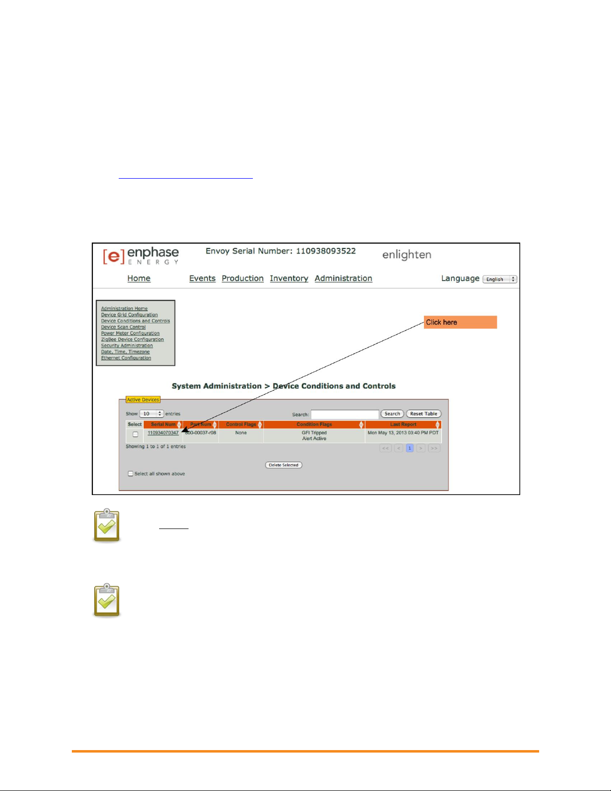
Troubleshooting an Enphase System
41
GFI Tripped
This condition occurs only with the M215, M190, D380, M210, M200, and M175 microinverters. A solid
red status LED on the microinverter indicates a ground fault (GFDI) error. The LED remains red and the
Envoy continues to report the fault until the error has cleared.
If a microinverter registers a GFI Tripped condition, you can attempt to clear this condition through the
Envoy Interface. An Envoy is required to send the clear-gfi message to clear the condition. If the
condition does not clear after you perform the following procedure, contact Enphase Energy customer
support at
To send the clear-gfi message to a microinverter:
support@enphaseenergy.com.
1. From the Administration menu, choose Device Conditions and Controls.
NOTE: Do not
check the box in the Select column.
2. Click on the serial number of the unit showing the GFI condition.
The Control Flags screen appears.
CAUTION: : Do not select the reboot and cmd-alert control flags unless recommended by
Enphase. The functions are:
reboot - reboots the inverter
cmd-alert - clears a condition flag for a command sent
2014 Enphase Energy Inc. August 2014
Page 42

42
3. In the clear-gfi menu, select set.
What is a “Utility Interactive” inverter?
The NEC (National Electric Code) defines this as, “An inverter intended for use in parallel with an
electric utility to supply common loads that may deliver power to the utility.” A utility-interactive
inverter lets PV system owners export excess power back to the utility.
Troubleshooting an Enphase System
4. Click Send Command.
Grid Gone
The microinverter reports that power from the utility is no longer present or is out of voltage or frequency
specification. In most cases, no action is required. Solar production resumes when conditions normalize.
Enphase microinverters are utility interactive and require a connection to the utility.
Verify that the solar circuit breakers are on at the load center. If all breakers are on, the condition
should clear itself.
If Grid Gone events repeatedly occur on one microinverter or only on portions of a branch, call
Enphase Customer Support for assistance.
2014 Enphase Energy Inc. August 2014
Page 43

Troubleshooting an Enphase System
43
Microinverter Failed to Report
A microinverter that reports a Microinverter Failed to Report condition is unable to communicate with
the Envoy over the AC power lines. Occasional instances of this error may be ignored as microinverter
communications will likely recover on the next reporting cycle.
Verify that the site has service from the electrical utility and that no solar circuit-breaker has
tripped.
If communications do not recover right away (the Envoy polls the microinverters every five
minutes), make sure that the Envoy is plugged in very near to the circuit breaker panel. Also, if
other devices are sharing the electrical outlet with the Envoy, remove those devices to improve
communication signal strength.
If the Envoy was recently relocated, or if new devices or appliances were added to the circuit, the
new location may not be suitable for power line communications. You may need to relocate the
Envoy to improve signal strength and reduce interfering noise on the power lines.
If several microinverters are reporting this condition, you may need to relocate the Envoy to
another electrical outlet to improve communication signal strength.
For further troubleshooting steps, see “Microinverters are not detected, or, power line communication
level is low or poor” on page 22.
Over Temperature
See “Critical Temperature” on page 37.
Zigbee Device Failed to Report
If the Envoy is connected to an Environ thermostat, this condition may occur if there is an interruption in
communication between the Environ thermostat and the Envoy.
Make sure the Envoy ZigBee USB stick is plugged into the Envoy. Occasional instances of this error may
be ignored, as a temporary interference to the radio signal may cause this condition and will recover on
its own. If this condition persists, it may be necessary to add a ZigBee repeater to boost signal strength
between ZigBee devices.
See the Environ Smart Thermostat Installation and Operation Manual at
for more information.
http://www.enphase.com/support
Zigbee USB Stick Removed
The Envoy Communication Gateway no longer detects the presence of the ZigBee USB stick. Make sure
that the ZigBee USB stick is fully seated in the Envoy USB port.
2014 Enphase Energy Inc. August 2014
Page 44

Troubleshooting an Enphase System
44
Best Practices
Installation sequence
Enphase considers following sequence of steps to be a best practice that reduces installation delays.
1. Register the System
2. Connect the Envoy Communications Gateway
3. Position the Enphase Engage Cable
4. Attach the Microinverters to the PV Racking
5. Dress the Cable
6. Connect the Microinverters
7. Terminate the Unused End of the Cable
8. Connect the Cable to the AC Junction Box
9. Complete the Installation Map
10. Connect the PV Modules
11. Energize the System
12. Use the Envoy to Complete System Setup
13. Build Array in Enlighten
Care of the solar array
How do I clean the solar array?
Visually inspect the array to check for dust, debris, leaves, and other soiling. If cleaning is needed, follow
the module manufacturer’s instructions for cleaning or contact a local professional to schedule a cleaning.
How do I maintain the solar array?
Installers may want to conduct an annual check of the integrity of mechanical and electrical connections.
An electrician can verify that the electrical connections are intact and working efficiently.
Many installers suggest that homeowners visually inspect the modules (panels), especially after storms
and in areas prone to hail and high winds. An inspection from the ground (use binoculars, if needed) is
usually sufficient.
At the array, get voltage readings from individual modules to confirm maximum performance and check
for problems not visible from the ground. For example, inspect the seals around the individual module
frames.
Installers can also check mechanical connections, perform a re-torque of all electrical connections,
confirm proper voltage and performance, and log cumulative data from the microinverters to keep and
compare performance records for the system.
Will a grid-tied solar array provide power during a power outage?
Grid-tied arrays cannot provide electrical power during electrical power outages. Safety requirements
dictate that grid-tied microinverters stop exporting power in the event of grid power loss.
2014 Enphase Energy Inc. August 2014
Page 45

Troubleshooting an Enphase System
45
Will the array provide power during when it is snowing or hailing?
Full sun is not required for the array to produce, but in poor weather, the panel production won’t be 100%.
On a cloudy day, the modules will produce at a much lower rate.
If snow is accumulates on the modules, production may be zero. Snow tends to slide off modules more
quickly than other roof surfaces, and the modules are usually installed in a south-facing direction. If snow
days are likely, then factor snow days into the system’s projected production.
Solar modules can tolerate rough weather. Most are designed to withstand ¾-inch hail at 120 miles per
hour, and they are also built to stand up to direct lightning strikes.
Can I add solar panels to the solar power system later?
Yes. Unlike arrays built with traditional string inverters, adding to the array is a simple procedure without a
lot of design constraints.
Other Questions?
Contact Enphase Customer Support at
support@enphaseenergy.com.
2014 Enphase Energy Inc. August 2014
 Loading...