

Page 1
Safety Instructions
DANGER: Before installing or using the Enphase Microinverter,
read all instructions and cautionary markings in the technical
description and on the Enphase Microinverter System and the
photovoltaic (PV) equipment.
DANGER: Do not use Enphase equipment in a manner not
specied by the manufacturer. Doing so may cause death or
injury to persons, or damage to equipment.
DANGER: Risk of Electrical Shock. Be aware that installation
of this equipment includes risk of electric shock. Do not install
the AC junction box without rst removing AC power from the
Enphase System.
DANGER: The Engage Cable terminator cap must not be
installed while power is connected.
WARNING: Normally grounded conductors may be ungrounded and energized when a ground fault is indicated.
WARNING: Always de-energize the AC branch circuit before
servicing. Never disconnect the DC connectors under load. Dis-
connect DC connections rst, then disconnect AC connections.
WARNING: Only use electrical system components approved
for wet locations.
WARNING: Only qualied personnel should troubleshoot,
install, or replace Enphase Microinverters or the Engage Cable
⚠
and Accessories.
WARNING: Make sure protective sealing caps have been
installed on all unused AC connectors. Unused AC connectors
⚠
are live when the system is energized by the grid. Sealing caps
may not be reused.
WARNING: Ensure that all AC and DC wiring is correct and
that none of the AC or DC wires is pinched or damaged. Ensure
⚠
that all AC junction boxes are properly closed.
WARNING: Do not leave AC connectors on the Engage Cable
uncovered for an extended period. If you do not plan to replace
⚠
the microinverter immediately, you must cover any unused connector with a sealing cap. Sealing caps may not be reused.
WARNING: DO NOT connect Enphase Microinverters to the
grid or energize the AC circuit(s) until you have completed all
⚠
of the installation procedures and have received prior approval
from the electrical utility company.
WARNING: Be aware that only qualied personnel must con-
nect the Enphase Microinverter to the utility grid.
⚠
WARNING: The Engage Cable terminator cap is intended for
one-time use only. If you open the terminator after initial instal-
⚠
lation, the latching mechanism is destroyed and the terminator
cap cannot be used again. If the latching mechanism is defective, the terminator must not be used. The latching mechanism
must not be circumvented or manipulated.
WARNING: When stripping the sheath from the Engage Cable,
make sure that the conductors are not damaged. If the exposed
⚠
wires are damaged, the system may not function properly.
WARNING: Perform all electrical installations in accordance with
all applicable local electrical codes and the National Electrical
⚠
Code (NEC), ANSI/NFPA 70.
NOTE: Check the labeling on the Engage Cable drop con-
✓
nectors to be sure that the cable matches the electrical utility
service at the site. Use 208 VAC (208 VAC three-phase) Engage
Cable at sites with three-phase 208 VAC service, or use 240
VAC Engage Cable at sites with 240 VAC single-phase service.
NOTE: When installing the Engage Cable, secure any loose
✓
cable to minimize tripping hazard.
NOTE: There are two release-holes in the drop connector on
✓
the Engage Cable. These are not for mounting but are used to
disconnect the connector. Keep these release holes clear and
accessible.
NOTE: When installing the Engage Cable and accessories,
✓
adhere to the following:
• Do not expose the connection to directed, pressurized liquid
(water jets, etc.).
• Do not expose the connection to continuous immersion.
• Do not expose the AC connector to continuous tension (e.g.,
tension due to pulling or bending the cable near the connection).
• Use only the connectors and cables provided.
• Do not allow contamination or debris in the connectors.
• Use the cable and connectors only when all parts are
present and intact.
• Fit the connections using only the prescribed tools.
• Use the terminator to seal the conductor end of the Engage
Cable; no other method is allowed.
NOTE: Protection against lightning and resulting voltage surge
✓
must be in accordance with local standards.
NOTE: If you need to remove a sealing cap, you must use the
✓
Enphase disconnect tool or a #3 Phillips screwdriver. Sealing
caps may not be reused.
®
ENGAGE QUICK INSTALL GUIDE
Installing the Engage Cable
The Engage™ Cable is a continuous length of outdoor-rated cable with integrated connectors for microinverters preinstalled
at intervals to accommodate various PV module orientations. Enphase Microinverters plug directly into the cable connectors.
Read and follow all warnings and instructions in the Engage Cable Installation Manual at
http://www.enphase.com/support before installing the Engage Cable.
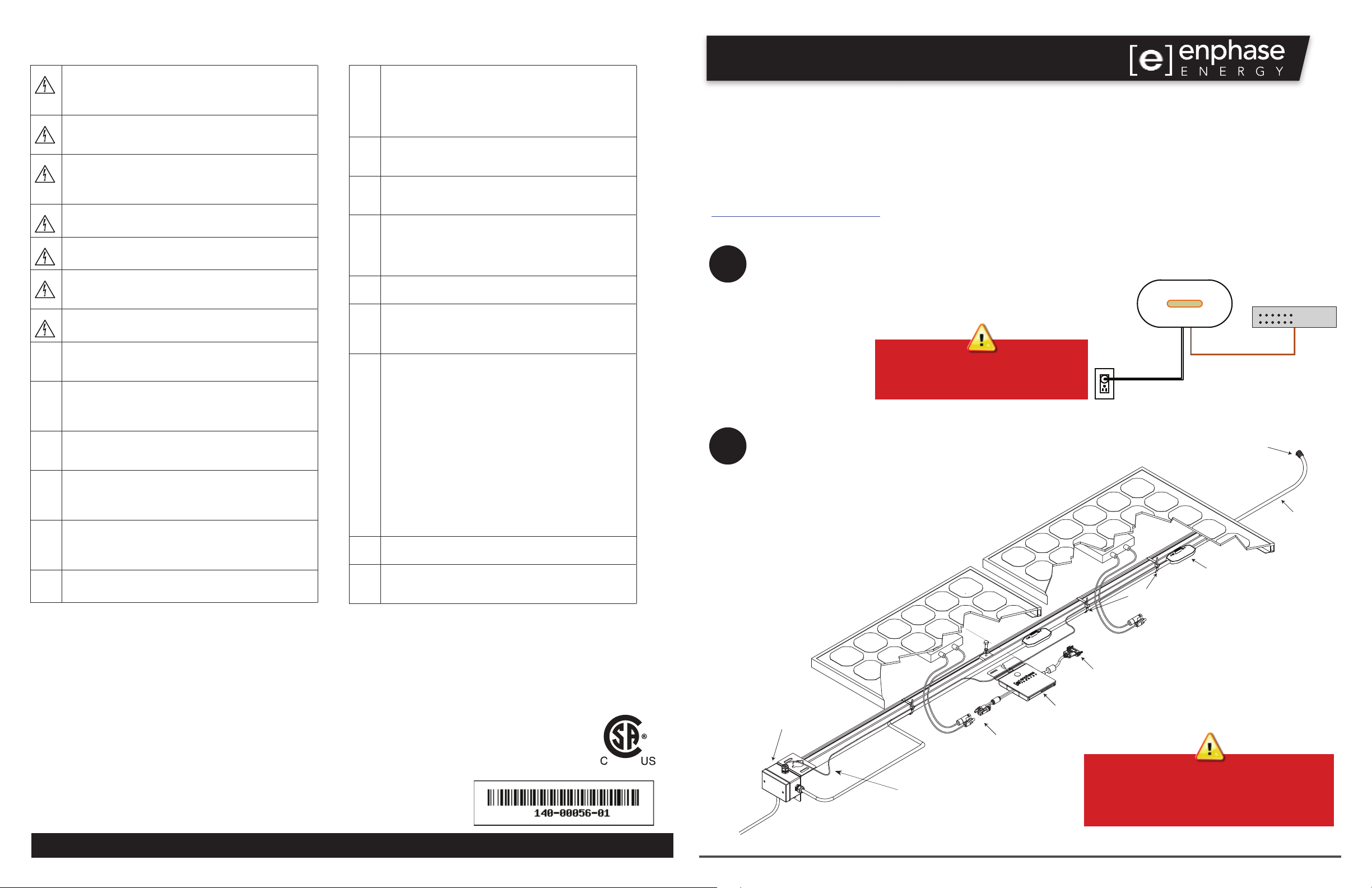
Connect the Envoy® Communications Gateway™
1
2
a. Connect the Envoy to power and Internet according to the Envoy Quick
Install Guide.
b. Look for the + Web indication on the LCD screen.
c. Leave the Envoy running while you install the microinverters
so that any required
Envoy software upgrade completes.
Warning: Do not remove power from
the Envoy if the LCD displays:
“Upgrading. . . Do Not Unplug.”
Position the Engage Cable
a. Lay out the cabling along the installed racking for
the AC branch circuit.
b. Install an appropriately rated, off-the-shelf junction
box at a suitable location on the racking.
See notes in Step Details.
Envoy
AC power
cord
cable ties
broadband
router
Ethernet cable
terminator
Engage Cable
drop connector
Enphase Energy, Inc.
1420 N. McDowell Blvd.
Petaluma, CA 94954
USA
[email protected]
http://www.enphase.com
© 2013 Enphase Energy Inc. All rights reserved.
AC junction box
DC connectors
GEC required for some
microinverter models
connects to
drop connector
microinverter
Check the drop connector labels to
be sure that you have the right cable.
You must use 240 VAC cable for single phase
or 208 VAC cable for three-phase.
Page 2
Engage Cable Quick Install Guide
3
4
5
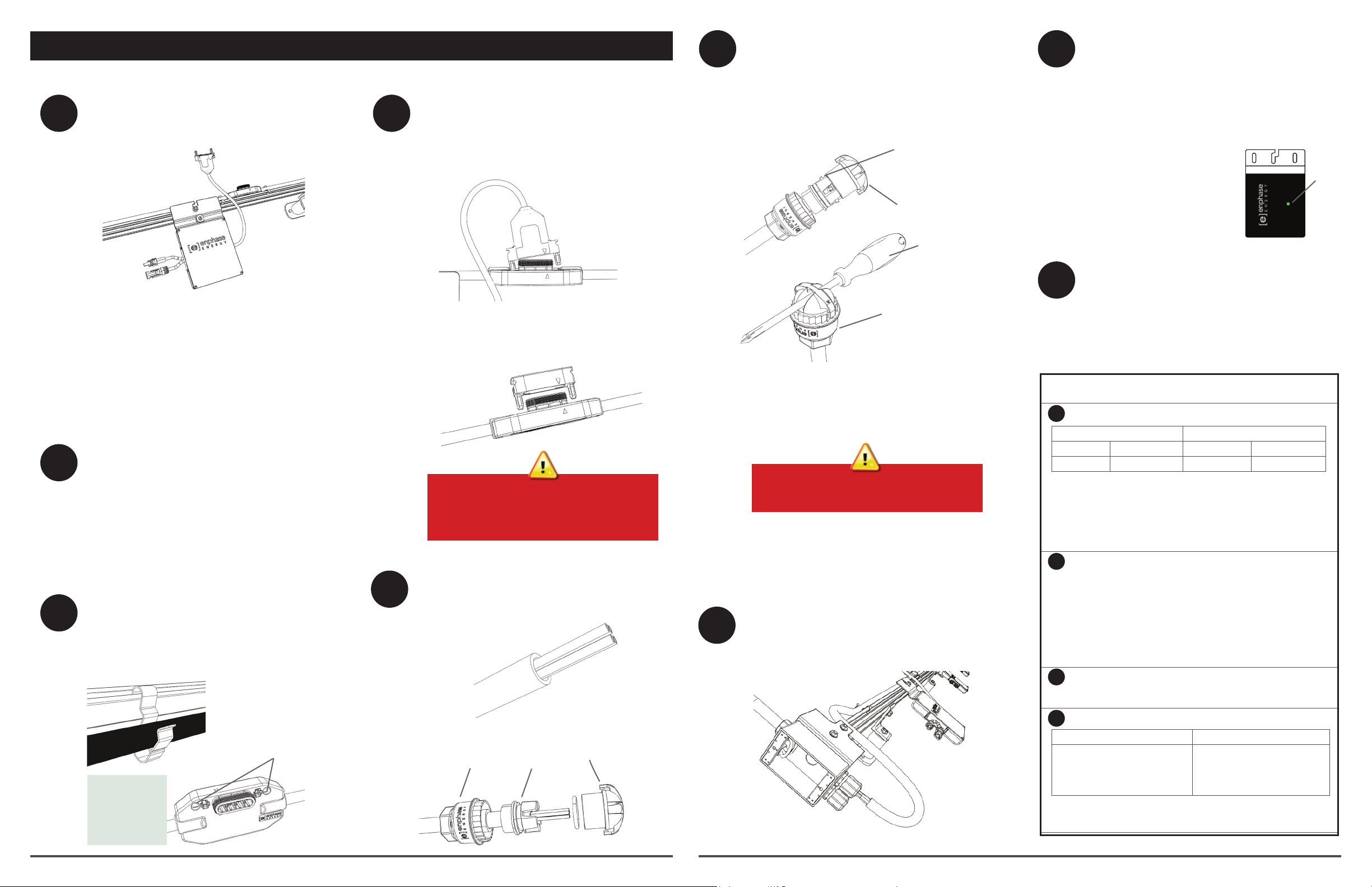
Attach the Microinverters to the PV Racking
a. Mark the approximate centers of each PV module
on the PV racking. See notes in Step Details.
b. Mount the microinverters under the PV module,
away from rain and sun. Do not mount the microinverter in a position that allows long-term exposure to
direct sunlight or in a vertical orientation that allows
water to collect in the DC connector recess.
c. Torque the microinverter fasteners as follows. Do not
over torque.
• 5 N m (45-50 in-lbs) for 6 mm (1/4”) hardware
• 9 N m (80-85 in-lbs) for 8 mm (5/16”) hardware
Ground the Microinverters (if required)
Route a continuous GEC (grounding electrode
conductor) on each branch if a GEC is required
for the microinverter type. Torque the grounding
cleat to 2 N m (20-25 in-lbs)
GEC Required?
• M250 Microinverter: No GEC required
• M215 Microinverter: GEC is required
Dress the Cable
a. Attach the cabling to the rack using cable
clips or tie wraps.
b. Dress any excess cabling in loops so that it
does not contact the roof.
cable clip
release holes
Keep the drop
connector
release holes
clear and
accessible.
7
Connect the Microinverters
6
a. Remove and discard the temporary shipping
cap from the cable connector and connect the
microinverter. Listen for two clicks as the
connectors engage.
b. Cover any unused connectors with sealing
caps. Listen for two clicks as the connectors
engage. See notes in Step Details.
Do not use shipping caps to cover
unused connectors. The shipping cap
does not provide an adequate
environmental seal.
Terminate the Unused End of the Cable
a. Remove 60 mm (2.5”) of the cable sheath
from the conductors.
b. Check that all terminator parts are present.
hex
nut
wire
organizer
cap
7
8
Terminate the Unused End of the Cable, Cont.
c. Slide the hex nut onto the cable.
d. Insert the cable end all the way into the wire
organizer (up to the stop).
e. Attach the cap.
bend wires down
into recesses of wire
organizer and
trim to length
place cap over
the wire organizer
hold the cap
with the disconnect tool or a #2
screwdriver
rotate the hex nut
with your hand or
a wrench until the
latching mechanism
meets the base–do
not over torque
f. Attach the terminated cable end to the PV
racking with a cable clip or tie wrap.
Never unscrew the hex nut. This action
can twist and damage the cable.
Connect the Cable to the AC Junction Box
Connect the cable into the AC branch circuit
junction box. See notes in Step Details.
9
Connect the PV Modules
a. Mount the 60-cell PV modules above the microin-
verters.
b. Connect the DC leads of each 60-cell PV module
to the DC input connectors of their corresponding
microinverter.
The status LED on the underside of each mi-
croinverter lights green six
seconds after DC power is
applied. It remains lit solid for
two minutes, followed by six
green blinks. After that, red
blinks indicate that no grid is
present. This is because the
system is not yet energized.
10
Energize the System
a. If applicable, turn ON the AC disconnect or circuit
breaker for the branch circuit.
b. Turn ON the main utility-grid AC circuit breaker.
Your system will start producing power after a
ve-minute wait time.
Step Details
2
NOTE: Verify that AC voltage at the site is within range:
240 Volt AC Single-Phase 208 Volt AC Three-Phase
L1 to L2 211 to 264 VAC L1 to L2 to L3 183 to 229 VAC
L1, L2, to N 106 to 132 VAC L1, L2, L3 to N 106 to 132 VAC
WARNING: Do not exceed the maximum number of microinverters in
an AC branch circuit as listed in the microinverter manual. Each branch
circuit must be protected by a dedicated circuit breaker of 20 A or less.
WARNING: Size the AC wire gauge to account for voltage drop for
both the branch circuit and all upstream conductors leading back to
the PCC. See the Circuit Calculations documents at http://www.
enphase.com/support.
3
WARNING: Allow a minimum of 1.9 cm (0.75”) between the
roof and the microinverter. Also allow 1.3 cm (0.50”) between the back
of the PV module and the top of the microinverter.
NOTE: Torque the microinverter fasteners to the values shown. Do not
over torque:
• 1/4” mounting hardware – 5 N m (45-50 in-lbs)
• 5/16” mounting hardware – 9 N m (80-85 in-lbs)
• If present, torque grounding cleat to 2 N m (20-25 in-lbs)
Using a power screwdriver is not recommended due to the risk of
thread galling.
6
WARNING: Install sealing caps on all unused AC connectors as
they become live when the system is energized by the utility. The IP67-
rated sealing caps are required for protection against moisture ingress.
8
NOTE: The Engage Cable uses the following wiring scheme.
240 Volt AC Single-Phase Wires 208 Volt AC Three-Phase Wires
Black – L1
Red – L2
White – Neutral
Green – Ground
NOTES: 1) The green wire acts as equipment ground (EGC).
2) The Engage Cable is stranded with Class K wire. Use appropriate
connectors when transitioning to eld cable.
Black – L1
Red – L2
Blue – L3
White – Neutral
Green – Ground
status
LED
 Loading...