

INSTALLATION MANUAL
Enphase AC Battery
2016-11 141-00036, Rev 01

AC Battery Installation
2
Contact Information
Enphase Energy Inc.
1420 N. McDowell Blvd.
Petaluma, CA 94954
enphase.com
enphase.com/en-us/support/contact
FCC Compliance
This equipment has been tested and found to comply with the limits for a Class B digital device, pursuant to
part 15 of the FCC Rules. These limits are designed to provide reasonable protection against harmful
interference in a residential installation. This equipment generates, uses and can radiate radio frequency
energy and, if not installed and used in accordance with the instructions, may cause harmful interference to
radio communications. However, there is no guarantee that interference will not occur in a particular
installation. If this equipment does cause harmful interference to radio or television reception, which can be
determined by turning the equipment off and on, you are encouraged to try to correct the interference by one
or more of the following measures:
Reorient or relocate the receiving antenna.
Increase the separation between the equipment and the receiver.
Connect the equipment into an outlet on a circuit different from that to which the receiver is
connected.
Consult the dealer or an experienced radio/TV technician for help.
Changes or modifications not expressly approved by the party responsible for compliance may void the
user’s authority to operate the equipment.
Environmental Protection
ELECTRONIC DEVICE: DO NOT THROW AWAY. Waste electrical products should not be disposed of
with household waste. Proper disposal of batteries is required. Refer to your local codes for
disposal requirements.
Other Information
For third-party license information, refer to enphase.com/licenses.
For Enphase patent information, refer to enphase.com/company/patents/.
Product information is subject to change without notice. All trademarks are recognized as the property of
their respective owners.
For warranty text, refer to enphase.com/warranty.
User documentation is updated frequently; Check the Enphase website (enphase.com/support) for the latest
information.
Read the Enphase Enlighten terms of service at enphase.com/en-us/legal/terms-of-service.
Copyright © 2016 Enphase Energy Inc. All rights reserved.
Audience
This manual is intended for use only by qualified electricians.
© 2016 Enphase Energy Inc. 141-00036 Rev 01

AC Battery Installation
3
Table of Contents
SAFETY ................................................................................................................................................. 4
In Case of Fire or Other Emergency ...................................................................................................... 4
Safety Instructions ................................................................................................................................. 4
The Enphase AC Battery ...................................................................................................................... 7
Block Diagram ...................................................................................................................................... 8
Planning ................................................................................................................................................ 8
Preparation ........................................................................................................................................... 8
Installing the AC Battery .................................................................................................................... 10
1. Choose a Location for the AC Battery ............................................................................................ 10
2. Install the Wall-Mount Bracket ........................................................................................................ 11
3. Install the AC Disconnect (if required) ........................................................................................... 12
4. Wire the Junction Box...................................................................................................................... 13
5. Mount the AC Battery on the Wall ................................................................................................... 14
6. Energize and Commission the System ........................................................................................... 15
Operation ............................................................................................................................................ 16
Charging and Discharging ................................................................................................................... 16
LED Overview ....................................................................................................................................... 16
Troubleshooting ................................................................................................................................. 17
LED is Solid Red or Not Lit ................................................................................................................... 17
Battery Information is Incorrect or Absent in Installer Toolkit or Enlighten ..................................... 17
Check the Internet Connection ..................................................................................................... 17
Run a Device Scan......................................................................................................................... 17
Relocate the Envoy ........................................................................................................................ 18
Check that Meters are Properly Configured ................................................................................ 18
Check that the Grid Profile and Rate Tariff are Set ..................................................................... 18
Battery LED is Off or Flashing Red ...................................................................................................... 18
Battery LED is Solid Amber ................................................................................................................. 19
System Alert: “AC Battery(ies) with Critical Temperature” ............................................................ 19
Removing or Replacing an AC Battery .............................................................................................. 20
Removing the AC Battery .................................................................................................................... 20
Re-installing the AC Battery ................................................................................................................. 21
Replacing the AC Battery ..................................................................................................................... 22
Technical Data .................................................................................................................................... 24
© 2016 Enphase Energy Inc. 141-00036 Rev 01
AC Battery Installation
4
DANGER:
This indicates a hazardous situation, which if not avoided, will result in death or serious
injury.
WARNING:
This indicates a situation where failure to follow instructions may be a safety hazard or
cause equipment malfunction. Use extreme caution and follow instructions carefully.
NOTE:
This indicates information that is very important for optimal system operation. Follow
instructions closely.
DANGER: Risk of
electric shock.
Risk of fire.
Do not attempt to repair the AC Battery; it contains no user-serviceable parts. No routine
maintenance is required. Tampering with or opening the AC Battery will void the warranty. Warranty
void if enclosure removed. If the AC Battery fails, contact Enphase Customer Support for assistance
at enphase.com/en-us/support/contact.
Only qualified electricians should install, troubleshoot, or replace the AC Battery.
SAFETY
To ensure the safe installation and operation of the AC Battery, note the following safety symbols that appear throughout
this document to indicate dangerous conditions and important safety instructions.
In Case of Fire or Other Emergency
In all cases:
If safe to do so, switch off the AC breaker for the AC Battery circuit, and if a disconnect switch is present, switch
off the AC disconnect for the AC Battery circuit.
Contact the fire department or other required emergency response team.
Evacuate the area.
In case of fire:
When safe, use a fire extinguisher. Suitable types are A, B, and C dry chemical fire extinguishers. Additional
extinguishing media include carbon dioxide, or alcohol-resistant foams.
In case of flooding:
Stay out of water if any part of the AC Battery or wiring is submerged.
If possible, protect the system by finding and stopping the source of the water, and pumping it away.
Let the area dry completely before use.
In case of unusual noise, smell or smoke:
Ensure nothing is in contact with the AC Battery or in the venting area on top of the AC Battery.
Ventilate the room.
Contact Enphase Customer Support at enphase.com/en-us/support/contact.
Safety Instructions
IMPORTANT SAFETY INSTRUCTIONS. SAVE THESE INSTRUCTIONS. This guide contains important instructions that you
must follow during installation and maintenance of the Enphase AC Battery. Failing to follow any of these instructions
may void the warranty (enphase.com/warranty). Follow all of the instructions in this manual. These instructions are key
to the installation and maintenance of the Enphase AC Battery™. These instructions are not meant to be a complete
explanation of how to design and install an energy storage system. All installations must comply with national and local
electrical codes and standards.
© 2016 Enphase Energy Inc. 141-00036 Rev 01
AC Battery Installation
5
DANGER: Risk of
fire or explosion.
Only qualified personnel, using personal protective equipment (PPE) should transport or handle the
AC Battery.
Do not dispose of AC Battery(ies) in a fire or by burning. The AC Battery(ies) can explode.
DANGER: Risk
of fire.
During use, storage, or transport, keep the AC Battery in an area that is well ventilated and protected
from the elements, where ambient temperature is between -4° F (-20° C) and 113° F (45° C), and
where relative humidity is between 5 and 95 percent. Do not install AC Battery at elevations over
6,000 feet (1,829 m) above sea level.
If the AC Battery generates smoke, remove AC power from the Enphase System so that
charging/discharging stops.
Do not allow or place flammable, sparking, or explosive items near the AC Battery.
DANGER: Risk
of electric
shock.
Do not use Enphase equipment in a manner not specified by the manufacturer. Doing so may cause
death or injury to persons, or damage to equipment.
Risk of electric shock. Be aware that installation of this equipment includes risk of electric shock. Do
not install the AC Battery without first removing AC power from the photovoltaic system. Disconnect
the power coming from the photovoltaics before servicing or installing.
In areas where flooding is possible, install the AC Battery at a height that prevents water ingress.
Always de-energize the AC branch circuit during an emergency and/or before servicing the AC
Battery. Never disconnect the DC connectors under load.
A battery can also present risk of high short-circuit current. Observe the following precautions when
working on batteries:
Remove watches, rings, or other metal objects.
Use tools with insulated handles.
Wear rubber gloves and boots.
Do not lay tools or metal parts on top of batteries.
Risk of electric shock. Risk of fire. Do not work alone. Someone should be in the range of your voice
or close enough to come to your aid when you work with or near electrical equipment.
WARNINGS:
Risk of property
or equipment
damage
During use, storage, transport, and installation, always keep the AC Battery in an upright position.
You must install the AC Battery only on a suitable wall using an Enphase wall-mount bracket.
Before installing or using the AC Battery, read all instructions and cautionary markings in the
technical description and on the equipment.
Do not install or use the AC Battery if it has been damaged in any way.
Do not exceed the maximum number (14) of AC Batteries in a 20A AC branch circuit.
Do not sit on, step on, place objects on, or insert objects into the AC Battery.
The AC Battery is not waterproof. Do not place beverages or liquid containers on top of the AC
Battery. Do not expose the AC Battery to liquids or flooding.
Damage to the battery can occur from over-discharge. While in storage, the AC Battery will discharge.
If the battery state of charge falls to 0%, the AC Battery can be damaged or destroyed. Because of
this, the AC Battery must only be stored for a limited amount of time.
The battery must be installed and energized by the “Must Energize By” date on the shipping box
label.
The battery must have a charge state of at least 30% when placed in storage.
If the AC Battery has already been installed, the battery must be placed into Sleep Mode prior to
uninstalling. An AC Battery in Sleep Mode can be stored a maximum of two months from the
date it was placed into Sleep Mode.
When placing the AC Battery in storage, ensure that the DC connector is unplugged.
© 2016 Enphase Energy Inc. 141-00036 Rev 01

6
NOTES:
Method of active anti-islanding protection: The AC Battery monitors for sudden changes in the
impedance of the grid by looking for changes in the second to the eighth harmonic. If significant
changes are detected, then the internal microinverter is de-energized thus preventing islanding.
Perform installation and wiring in accordance with all applicable local electrical codes and
standards.
Protection against lightning and resulting voltage surge must be in accordance with local standards.
Using unapproved attachments or accessories could result in damage or injury.
Use Class 1 wiring methods for field wiring connections to terminals of a Class 2 circuit. Use only 12
AWG (2.5 mm2) to 20 AWG (4 mm2) wire in the junction box terminal block. Select the wire size
based on the protection provided by the circuit breakers / fuses. Install properly rated over current
protection as part of the system installation.
To ensure optimal reliability and to meet warranty requirements, the AC Battery must be installed
and/or stored according to the instructions in this guide.
The Enphase AC Battery is compatible only with the Enphase Envoy-S Metered communications
gateway with properly installed production and consumption CTs. The Envoy-S is required for
operation of the AC Battery. Earlier versions of the Enphase Envoy communications gateway, and the
Envoy-S Standard gateway are incompatible.
The Enphase AC Battery is intended to operate with an internet connection. Failure to maintain an
internet connection may have an impact on the warranty. See http://enphase.com/warranty for full
terms and services.
When replacing an Enphase AC Battery, you must replace it with an AC Battery of the same type, with
the same AC current rating.
When stored, the AC Battery is not connected to the grid and no automatic charge of the battery is
possible.
Properly mount the AC Battery or place it on a flat, plain surface that can bear heavy weights. Ensure
that the mounting location is structurally suited to bearing the weight of the AC Battery.
During use, storage, and transport, keep the AC Battery:
Properly ventilated
Away from water, other liquids, heat, sparks, and direct sunlight
Away from excessive dust, corrosive and explosive gases, and oil smoke
Away from direct exposure to gas exhaust, such as from motor vehicles
Free of vibrations
Away from falling or moving objects, including motor vehicles
At an elevation of fewer than 6,000 feet (1,829 m) above sea-level
In a location compliant with fire safety regulations (has a smoke detector)
In a location compliant with local building codes and standards
Conditions for the AC Battery installation site apply also to storage conditions.
AC Battery Installation
© 2016 Enphase Energy Inc. 141-00036 Rev 01
AC Battery Installation
7
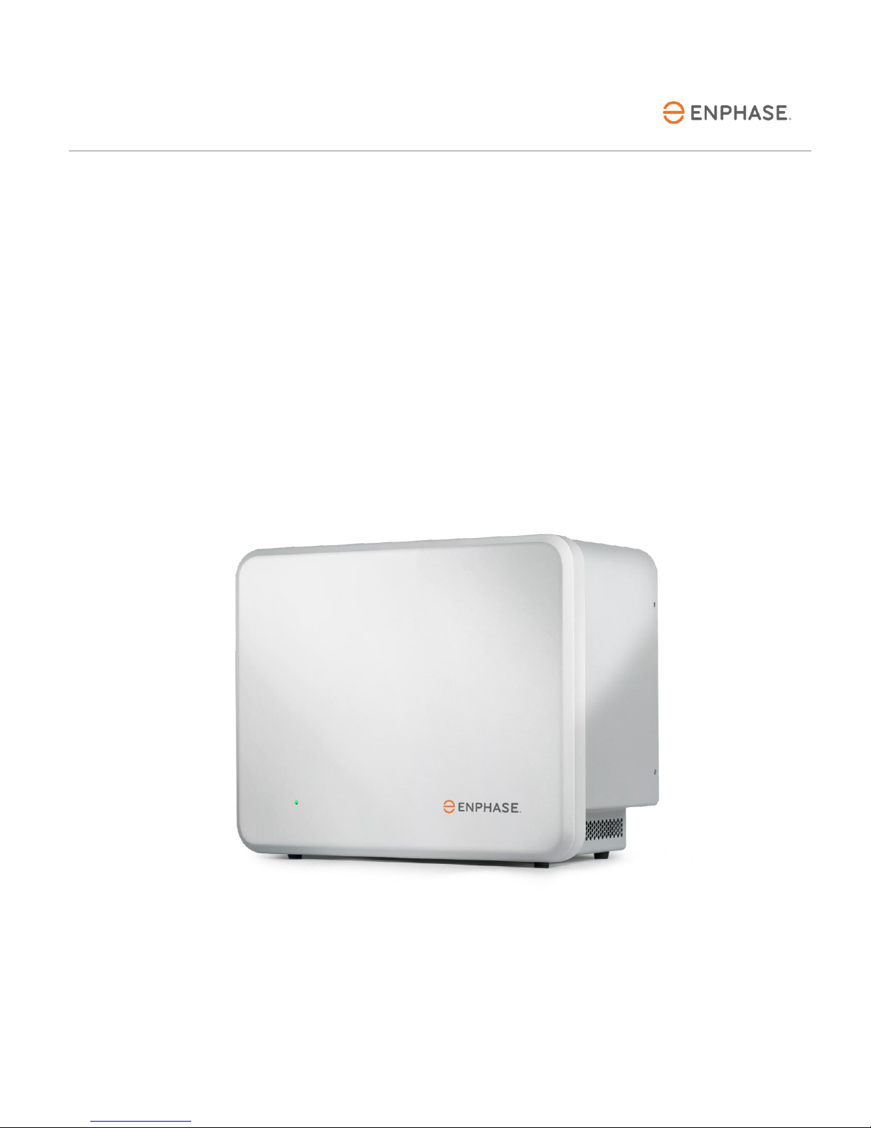
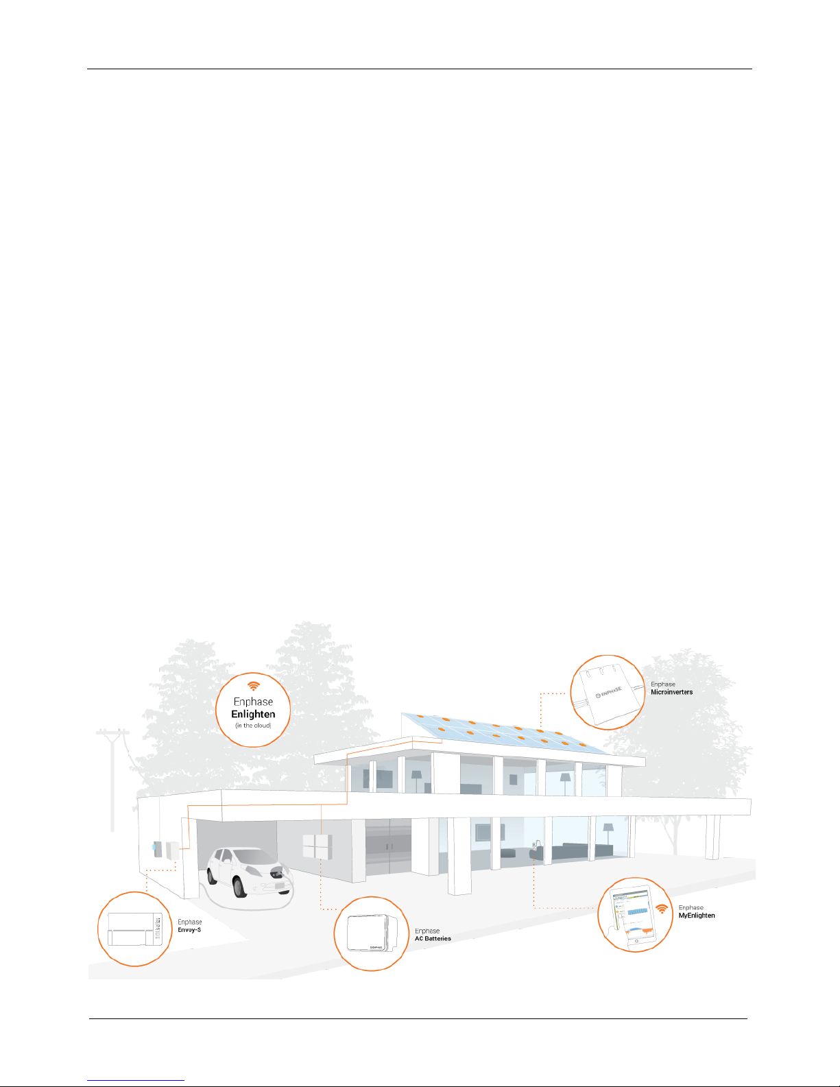
The Enphase AC Battery
The Enphase AC Battery™ is the heart of the Enphase Storage System. The AC Battery is simple to install,
safe, very reliable, and provides the lowest lifetime energy cost for both new solar customers and retrofit
customers. You can install as many batteries as needed to meet the needs of the system owner.
The Enphase Storage System includes the Enphase AC Battery with integrated Enphase Microinverter™. The
system uses the Enphase Envoy-S Metered™ to measure PV production and home energy consumption. The
system knows when it is optimal to charge or discharge the battery so that energy is stored when it is
abundant and used when scarce.
The Enphase Envoy-S Metered operates as a gateway between the storage system and Enphase
Enlighten™ web-based monitoring and analysis software. The Envoy-S monitors and controls the AC
Battery through the integrated Enphase Microinverter. It collects energy and performance data from
all Enphase Microinverters at the site over on-site AC power lines, and it forwards that data to
Enlighten, via the Internet, for statistical reporting and system control. The Enphase Envoy-S Metered
communications gateway with properly installed production and consumption CTs is required for
operation of the AC Battery.
When used with non-Enphase PV systems, the Envoy-S can collect production and consumption
data, but it does not control grid management functions of non-Enphase PV system components.
The Enphase Enlighten™ web-based monitoring and analysis software analyses the data collected by
the AC integrated microinverter in the AC Battery. Enlighten constantly monitors every Enphase
Microinverter connected to the Envoy-S and is essential for system monitoring and troubleshooting.
Enlighten provides a wide range of information on system performance. You can access Enlighten
on your computer or mobile device at any time.
The Enphase Microinverter converts the DC output of the PV module into grid-compliant AC power.
In addition to performing the DC to AC conversion, it maximizes energy production by using a
sophisticated Maximum Power Point Tracking (MPPT) algorithm.
© 2016 Enphase Energy Inc. 141-00036 Rev 01
8
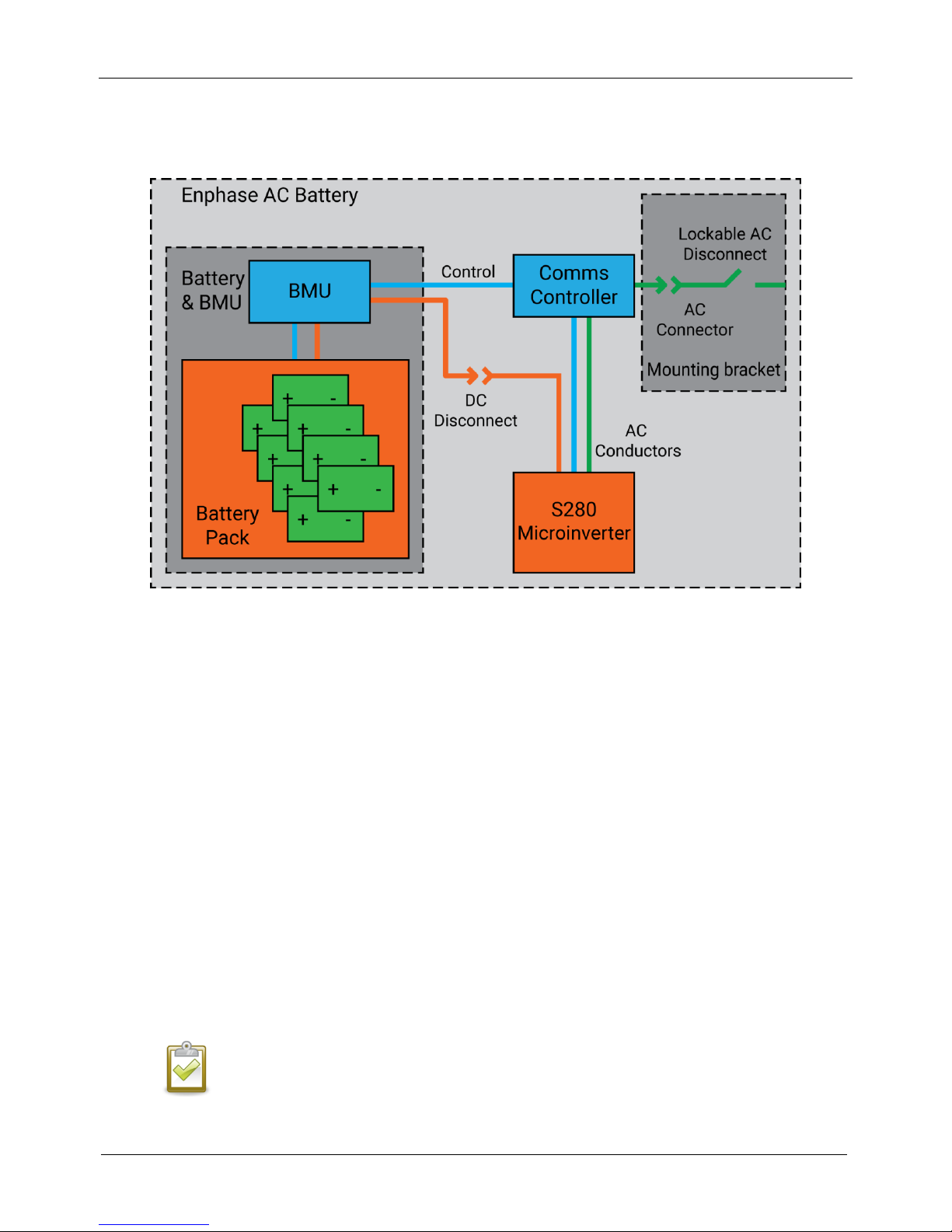
Block Diagram
AC Battery Installation
Planning
The Enphase AC Battery is controlled by the Enphase Envoy-S Metered gateway. The AC Battery cannot
function if it is not receiving commands from the Envoy-S. For that reason, it is critical that the Envoy-S and
AC Battery(ies) are located as close as possible to each other. The Envoy should be located within 65 feet
(20 m) electrical distance from the AC Battery(ies).
However, this may not always be practical since the Envoy-S Metered also needs to be connected to the
production and consumption CTs that are installed around the main service and solar production circuits. In
this case, you may need to extend the CTs and reroute the solar circuit to a location closer to the AC
Battery(ies). One solution is to install the AC Battery, the solar production circuits, and the Envoy-S off a
common subpanel.
Preparation
a. Ensure that you have both of the following:
One or more Enphase AC Battery(ies) (Model B280-1200-LL-I-US00-RF0): the AC Battery shipping
box contains an Enphase AC Battery and an access panel cover.
NOTE: Check the “Must Energize By” label on the shipping box to verify that the AC Battery
will be installed by the date shown.
© 2016 Enphase Energy Inc. 141-00036 Rev 01

AC Battery Installation
9
One Enphase Wall-Mount Bracket (BWM-16IN-B) for each battery. The wall-mount bracket
shipping box includes only the bracket. The brackets are sized to accommodate standard
residential stud spacing of 16 inches.
b. Make sure you have the following required items:
Enphase Envoy-S Metered communications gateway with production CT(s) and consumption
CT(s) installed and configured as described in the Enphase Envoy-S Metered Quick Install Guide.
When used with Enphase devices, the Envoy-S can control grid management functions and
monitor PV production and site consumption. When used with non-Enphase PV systems, it can
collect production and consumption data, but it does not control grid management functions of
non-Enphase PV system components.
NOTE: The Enphase AC Battery requires an internet connection (through the Envoy-S).
Maintaining this connection is important, not only for updating software and firmware, but
also for measuring the health of the battery. Failure to maintain an internet connection may
have an impact on the warranty. See enphase.com/warranty for full terms and services.
Mounting location that is structurally suited to bearing the weight of the AC Battery. The wall
must have appropriately spaced studs (16 in) or can be of masonry or other suitable structure.
NOTE: If the wall is not structured in a way that allows wall mount brackets to be attached
directly to the studs, a substructure is required, such as 1) metal strut, ¼ inch spring nuts,
and ¼ inch bolts or 2) horizontally mounted wood studs or strong plywood.
Tools: conduit fitting tools, drill, 5/32 in (4 mm) pilot bit, screwdriver, socket, wrench, adjustable
wrench, torque wrench, level, 5/32 in (4 mm) Allen key, and wire stripper.
Four ¼-inch (6 mm) diameter lag bolts/screws, 1 to 2 inches (25 to 50 mm) long depending on
attachment wall, for each wall-mount bracket. Check with a structural engineer and local
standards for requirements specific to your site.
Washers for use between fastener heads and wall-mount bracket.
Copper conductors for push terminals: 12 AWG (2.5 mm
2
to 4 mm2) rated at 75° C or 90° C. Strip
to 7/16 inch (11mm).
Gland or strain relief fitting: one for each used conduit opening in the AC junction box.
OCPD: 20A maximum over current protection and readily accessible disconnecting means in
accordance with local code requirements.
Personal protective equipment (PPE) for handling lithium ion batteries as required by local safety
standards.
c. Make sure you have the following optional items, if needed:
20A maximum AC disconnect
Conduit or raceway and fittings
Stud finder
d. Install the PV system and the Envoy-S as directed by the installation manuals.
e. To record the location(s) of the AC Battery(ies), peel the removable serial number label from each
battery and affix it to the respective location on a paper installation map. You will scan this map later
using the Enphase Installer Toolkit™ and your mobile device.
NOTE: If needed, you can find an installation map at the back of any Enphase Microinverter
manual. Always keep a copy of the installation map for your records.
© 2016 Enphase Energy Inc. 141-00036 Rev 01

10
Installing the AC Battery
Choose a location for the
AC Battery
Install the wall-mount
bracket
Install the AC disconnect
(if required)
Wire the junction box
Mount the AC Battery on
the wall
Energize the system
Steps one through four describe installation of the wall-mount bracket
and junction box wiring, while steps five and six describe mounting the
battery and energizing the system.
1. Choose a Location for the AC Battery
The AC Battery housing is a NEMA type 2 metallic enclosure. The
terminal blocks on the wall-mount bracket accept a maximum
conductor size of 12 AWG (4 mm2).
a. Following local standards, choose a wall in a readily
accessible, well-ventilated, indoor location (like a garage),
which is out of direct sunlight and where the ambient
temperature and humidity are within -4° F (-20° C) and 113° F
(45° C) and 5% to 95% RH, non-condensing.
AC Battery Installation
NOTE: If the AC Battery registers a high temperature
event, it responds by reducing operation to correct
internal temperature.
b. Ensure that the mounting location can sustain the weight of
the AC Battery and wall-mount bracket (60 lbs. or 28 kg per
battery).
c. Plan the mounting location to be at least one foot (300 mm)
off the ground and one foot (300 mm) from the ceiling. Keep
the battery(ies) away from falling or moving objects, including
motor vehicles.
d. Ensure that there are no pipes or electrical wires where you
plan to drill.
e. Plan to maintain at least one foot (300 mm) of clearance in front of each battery.
f. Consider the dimensions of the AC Battery, easy access, height, and length of cable when selecting
the location.
g. Do not block the vents or allow liquids to contact the AC Battery. The AC Battery is not waterproof.
h. Select a location where you can interconnect to the site’s load center using an appropriate branch
circuit.
i. Following local standards, decide whether to connect using external conduit or by wiring inside the
walls. This determines which knockouts to use in the junction box. Check if an AC disconnect is
needed. Plan the location for the AC disconnect switch, if needed.
j. If you are installing more than one AC Battery, continue to maintain minimum required clearances as
shown in Step 2.
© 2016 Enphase Energy Inc. 141-00036 Rev 01

AC Battery Installation
11
2. Install the Wall-Mount Bracket
a. Make sure that the wall-mount bracket matches the wall stud spacing and that the lowest wall-
mount bracket position meets clearance requirements as shown.
WARNING! Risk of injury and equipment damage. Protect the AC Battery from damage and
improper use.
b. Remove the appropriate knockout(s) for the planned entry into the wall-mount bracket junction box:
If wiring inside the walls, use the knockout(s) in the back of each junction box. If using conduit,
use the knockouts at the bottom of the junction box.
If installing only one battery or if installing the last battery in an array, use only one knockout.
Loosen the screw securing the junction box cover and remove the cover. Keep the cover handy
as you will need it
later.
c. Starting at battery
position closest to the
power source, mark a
level line on the wall as a
guide.
WARNING!
Multiple risks.
Make sure not to
drill or attach into
electric wiring or
pipes that are in
the wall!
d. Place the wall-mount
bracket on the wall so
that the mark on the
bracket aligns with the
center of the stud. Use a
level to keep the top of
the wall-mount bracket
flat, and attach each
corner of the wall-mount
bracket using one screw
and washer for each slot.
e. Verify that the wall-mount bracket is solidly attached to the wall.
WARNING! Risk of injury and equipment damage. Do not mount an AC Battery on a bracket
that is not properly mounted.
f. If installing additional batteries, install the adjacent wall-mount brackets in an interleaved fashion, as
needed. Be sure to align the mark on the adjacent wall-mount bracket to the center of the wall stud.
A small overlap in adjacent wall-mount brackets is normal. You may install another row of wallmount brackets above the one already installed. Maintain at least one foot (300 mm) clearance
between rows.
© 2016 Enphase Energy Inc. 141-00036 Rev 01

12
16.0 in
19.2 in
14.0 in
35.2 in
The wall-mount bracket allows 16-inch battery-to-battery spacing:
AC Battery Installation
3. Install the AC Disconnect (if required)
Following all local codes and standards:
a. Choose an AC Disconnect that can break the maximum rated current of the branch circuit under load
(20 A maximum).
b. Connect one side of the disconnect to the load center:
c. Verify that AC voltage at the site is within range. Single-phase L1 (Active) to L2 must measure
between 211 and 264 VAC, while L to N should measure between 106 and 132 VAC.
WARNING! Risk of equipment failure. Size the conductor gauge to account for voltage rise
for both the branch circuit and all upstream conductors leading back to the PCC (point of
common coupling). Refer to the technical brief on voltage rise at enphase.com/support.
© 2016 Enphase Energy Inc. 141-00036 Rev 01

AC Battery Installation
13
4. Wire the Junction Box
a. Size the conductors (Line, Neutral and Ground) depending on the upstream breaker or fuse. Use 12
AWG to 20 AWG (2.5 mm2 to 4 mm2) wire with maximum 20A branch circuit protection.
DANGER! Risk of electric shock. Check that the dedicated circuit breaker protecting the
branch where the AC Battery will be connected is turned off before wiring.
WARNING! Risk of equipment damage. Always connect to two Lines (active) and to one
Neutral.
b. Using the conductors and suitable conduits, connect the AC disconnect (if used) and the first
adjacent AC Battery junction box. Use the openings provided by the knockouts to connect the
conduit and pass the wires through them.
NOTE: Do not modify or rewire the pre-installed wiring or bonding connections in the junction
box.
c. Connect each wire in the junction
box to its corresponding conductor
(Line, Neutral and Ground). Each
push terminal accepts two 12 AWG
to 20 AWG (2.5 mm2 to 4 mm2)
conductors (7/16-inch strip length).
Use a screw driver to depress the
terminal.
d. After all wires in the junction box
are connected and secured, check
that there are no exposed
conductors.
e. If connecting additional AC
Batteries, use another conduit and
set of wires to connect out of the
junction box to the next junction
box.
f. Gently arrange all the wires and
connectors inside the junction box
and replace the cover. Tighten the
cover screw using a Phillips screw
driver.
DANGER! Risk of electric
shock. The system is not
ready to be energized! Do
not close the circuit
breaker yet.
© 2016 Enphase Energy Inc. 141-00036 Rev 01

AC Battery Installation
14
Bottom view (access panel removed)
5. Mount the AC Battery on the Wall
WARNING: Risk of injury and equipment damage. You must mount the AC Battery to a
suitable wall.
WARNING: Risk of injury and equipment damage. Avoid dropping the AC Battery. Doing so
may create a hazard, cause serious injury, and/or damage the equipment.
WARNING: Before mounting the Enphase AC Battery, ensure that the junction box cover is
secured!
WARNING: Take care when lifting the AC Battery. The AC Battery is heavy and may require
two persons to lift.
a. Using both hands, take the AC Battery from the packaging and place it right side up on a flat surface.
Be sure that the AC connector is not pinched underneath.
NOTE: Never leave the battery on its back for more than five minutes. The battery cells are
meant to be in the upright position.
b. Begin by installing the AC Battery located closest to the main supply. Using the two grip insets on the
side of the AC Battery, lift and carry the AC Battery to the installed wall-mount bracket.
c. While setting the AC Battery onto the wall-mount bracket, ensure that the four tabs on the AC Battery
are inserted into their corresponding openings in the wall-mount bracket. After the tabs are inserted,
begin lowering the AC Battery slowly to ensure that the tabs have latched onto the wall-mount
bracket.
WARNING: Risk of injury and equipment damage. Do not release the AC Battery until you
ensure that all four tabs have safely latched onto the wall-mount bracket.
© 2016 Enphase Energy Inc. 141-00036 Rev 01

AC Battery Installation
15
WARNING: Risk of equipment damage. When placing the AC Battery on the wall-mount
bracket, ensure that the junction box does not pinch the DC connector, the AC connector, or
its cable.
d. Use a Phillips #2 screwdriver to secure the two bond screws into the wall-mount bracket. The bond
screws are accessible through the bottom access compartment. The bond screws provide a
grounding bond between the AC Battery and the wall-mount bracket.
WARNING: Always secure the bond screws to ensure grounding bond and firm mechanical
attachment of AC Battery to wall-mount bracket.
e. Plug the DC connector into DC socket. Listen for a clicking sound as the connectors engage.
NOTE: This action connects the internal battery to the internal electronics; you must
disconnect it if you move the AC Battery.
NOTE: Check that the wall-mount bracket junction box is fully inside the access
compartment of the AC Battery. The AC Battery must not rest on the junction box or rely on it
for support.
f. Connect the battery AC connector into the AC connector on the junction box. Listen for a clicking
sound as the connectors engage.
g. Attach the bottom access plate and secure the two compression half-turn latches using a 5/32-inch
(4 mm) Allen key.
6. Energize and Commission the System
WARNING: Before energizing the system, make sure ALL AC Batteries in the system are
properly installed and conductors terminated.
a. Check that the AC Battery bottom access plates on all AC Batteries in the system are closed and
secured.
b. Turn on the circuit feeding the AC Battery(ies).
c. The AC Battery LED should now be solid red for the duration of the start-up process. If the LED is not
solid red, see following section on Troubleshooting.
d. Use the Enphase Installer Toolkit to commission the AC Battery(ies). Once connected to the Envoy,
refer to the Installer Toolkit help topics for more information.
e. After the Envoy-S has detected the AC Battery(ies), the AC Battery LEDs operate as described in the
following section.
© 2016 Enphase Energy Inc. 141-00036 Rev 01

AC Battery Installation
16
State
Description
Solid red
Starting up
Red flashes in sequences of two
Error. See “Troubleshooting”.
Solid amber
Not operating due to high temperature. See
“Troubleshooting”.
Solid blue or green
Idle. Color transitions from blue to green as state
of charge increases. You can check Enlighten for
charge status.
Slowly flashing blue
Discharging
Slowly flashing green
Charging
Green one second flashing
Looking for noncommissioned unit
Off
Not operating. See “Troubleshooting”.
Operation
The following sections describe operation of the AC Battery.
Charging and Discharging
The charging and discharging functions are controlled by the Envoy-S as follows:
Charging: The AC Battery typically charges during daylight hours and when the solar production is greater
than the home consumption. The AC Battery can also be programmed to charge from the electric grid at
night under certain conditions.
Discharging: The AC Battery discharges power only to service local loads. It does not discharge power
through the utility meter onto the electric grid. The AC Battery discharges for use by the home if all of the
following occur:
The consumption exceeds the production
The actual time of day is after the peak start time, if time of use is configured
The batteries are not fully discharged. If the batteries are fully discharged, then they must recharge
from the PV system before they can discharge again.
LED Overview
The LED glows red while the AC Battery boots up. If the LED remains red for more than two minutes, the
battery is in trickle charge mode and will remain so until it reaches a minimum state of charge (up to 30
minutes). After the AC Battery is booted up, the LED becomes blue or green (depending on the charge level).
If the LED remains red after one hour or changes to a flashing red state, contact Enphase Customer Support
at enphase.com/en-us/support/contact.
Other LED states include:
© 2016 Enphase Energy Inc. 141-00036 Rev 01

AC Battery Installation
17
Troubleshooting
The following sections describe possible problems and solutions.
During installation, use the Enphase Installer Toolkit mobile app to verify AC Battery operation. The Installer
Toolkit, when used with the Envoy-S provides information about the status of the AC Battery, the PV
production, and the home energy consumption.
LED is Solid Red or Not Lit
If, after start up, the AC Battery LED is red
or not lit, check that the proper voltage
(240V line-to-neutral) is provided to the AC
Battery. To do this:
Remove the access cover on the
bottom of the battery.
Check that both the AC and DC
connectors are fully seated in the
receptacles.
Unplug the AC connector and test
the voltage and frequency at the
terminals of the junction box. You
should detect approximately
240V/60Hz between the red, black
and white terminals.
Battery Information is Incorrect or Absent in Installer Toolkit or Enlighten
The Envoy-S manages the charging and discharging operations of the AC Battery. Ensure that the Envoy-S
current transformers (CTs) are correctly installed and that production and consumption metering are
configured correctly in Installer Toolkit. Once this is done, you can use the Installer Toolkit to check that the
Envoy-S has detected devices and that they are communicating.
Check the Internet Connection
If you do not see AC Battery information in Enlighten, check that the Envoy-S and the Internet connection are
working.
Run a Device Scan
If needed, you can also provision devices either by scanning the AC Battery(ies) bar code(s) or by performing
a device scan. If the AC Battery(ies) cannot be detected by the device scan or if the AC Battery(ies) are not
communicating, you need to relocate the Envoy-S to be electrically closer to the AC Battery(ies). This is
because the Envoy-S communicates with the AC Battery using power line communications. The Envoy-S and
AC Battery(ies) must be installed on the same phase.
© 2016 Enphase Energy Inc. 141-00036 Rev 01

AC Battery Installation
18
Relocate the Envoy
When possible, locate the Envoy-S within 65 feet or 20 meters (electrically) from the AC Batteries. This may
not always be practical since the Envoy-S must also be connected to the production and consumption CTs
that are installed around the main service and solar production circuits. If so, you can extend the CT leads as
described in the Envoy-S Installation and Operation Manual. In addition, the solar circuit may need to be
rerouted to a location closer to the AC Batteries. One solution is to install the AC Battery, the solar
production circuits and the Envoy-S Metered off a common subpanel.
Check that Meters are Properly Configured
If the consumption and production metering are not configured and operating properly, the AC Battery will
not operate or will operate improperly. The Envoy-S Metered uses the consumption and production meter
readings to determine if the AC Battery should be charging or discharging. Confirm in Installer Toolkit that
the consumption and production metering are both Enabled. A check next to both production and
consumption metering verifies that the metering is enabled. Additional checks include:
a. To check that the consumption meter is installed correctly, shut off both the solar production and AC
Battery circuits. The consumption meter reading should closely match the utility meter’s reported
power reading.
b. If the consumption meter is installed and operating correctly, turn on the solar production circuits,
but leave the AC Battery circuit(s) off. The solar production reading should be positive.
c. Turn on the AC Battery circuit(s). Note that the consumption readings are impacted by the battery
operation. AC Battery charging increases the consumption reading. Since a portion of the PV
production is used to charge the batteries, the home’s consumption will appear to increase during
charging. When the batteries are discharging, the consumption metering reports the load
consumption lower than actual.
If any of these checks show incorrect results, check the Envoy-S and CT wiring against the appropriate wiring
diagram in the Envoy-S Installation and Operation Manual
Check that the Grid Profile and Rate Tariff are Set
Check that the Grid Profile has been set in Installer Toolkit. If needed, set the Peak Start Time and the Time
of Use rate tariff in Installer Toolkit to control the time of day that the batteries begin to discharge to feed
loads.
Battery LED is Off or Flashing Red
If the AC Battery is not working correctly, perform the following steps. If the issue persists, contact Enphase
Customer Support at enphase.com/en-us/support/contact.
If the AC Battery LED is off, turn off the breaker for the branch circuit, wait for at least one minute,
and turn it back on.
During a brownout or blackout, the AC Battery powers down automatically. This is normal. When
power is restored, it automatically starts up again.
© 2016 Enphase Energy Inc. 141-00036 Rev 01

AC Battery Installation
19
Battery LED is Solid Amber
Check the temperature in the room and increase cooling and/or ventilation as required to meet
temperature requirements. The AC Battery requires an ambient temperature between -4° F (-20° C)
and 113° F (45° C), and where relative humidity is between 5 and 95 percent.
Check that the front, top, and sides of the AC Battery array have at least one foot of unobstructed
clearance.
NOTE: If the AC Battery registers a high temperature event, it responds by reducing
operation to correct internal temperature.
System Alert: “AC Battery(ies) with Critical Temperature”
Check the temperature in the room and increase cooling and/or ventilation as required to meet
temperature requirements. The AC Battery requires an ambient temperature between -4° F (-20° C)
and 113° F (45° C), and where relative humidity is between 5 and 95 percent.
Check that the front, top, and sides of the AC Battery array have at least one foot of unobstructed
clearance.
NOTE: If the AC Battery registers a high temperature event, it responds by reducing
operation to correct internal temperature.
© 2016 Enphase Energy Inc. 141-00036 Rev 01

AC Battery Installation
20
Removing or Replacing an AC Battery
If problems remain after following the troubleshooting steps above, contact Enphase at enphase.com/en-
us/support/contact.
DANGER! Risk of electrocution! Do not disconnect the consumption CT leads from the terminal
block while the sensed circuit is energized.
DANGER! Risk of electric shock. Risk of fire. Do not attempt to repair the Enphase AC Battery; it
contains no user-serviceable parts. Tampering with or opening the Enphase AC Battery will void
the warranty. If the AC Battery fails, contact Enphase Customer Support for assistance at
enphase.com/en-us/support/contact.
Warranty void if the Enphase AC Battery housing is removed.
Refer servicing to qualified personnel.
DANGER! Risk of electric shock. Always de-energize the load center before beginning wiring.
WARNING! The AC Battery must have a charge state of at least 30% when placed in storage.
After the AC Battery has been installed, you can store it subsequently for a maximum of two
months. When placing the AC Battery in storage, ensure that the DC connector is unplugged
from the DC socket.
Removing the AC Battery
In the event that one or more AC Batteries needs to be temporarily uninstalled, or if Enphase Customer
Support authorizes an AC Battery replacement (RMA), perform the following steps.
1. Prior to uninstalling an AC Battery, you must initiate battery Sleep Mode to ensure that the state
of charge is not too high or too low for storage or transport. Once Sleep Mode is initiated, the AC
battery will continue to operate until it reaches the desired state of charge. Since the rate at
which the AC battery can charge or discharge is governed by the loads connected at the point of
coupling, it can take several hours for the desired state of charge to be reached and for the AC
Battery to ‘Fall Asleep’. Therefore, Enphase recommends that you initiate Sleep Mode 24-48
hours in advance of the physical removal of the AC Battery. This is to ensure that sufficient time
has passed to allow the AC battery to ‘Fall Asleep’. You can initiate Sleep Mode in one of three
ways:
Remotely (Recommended). Using Enlighten Manager, you can remotely enable one or
more AC Batteries to initiate Sleep Mode by selecting this option under the Devices tab.
At the site. Using the Installer Toolkit App, you can connect to the Envoy and enable
Sleep Mode for one or more AC Batteries using the Storage button on the App.
Enphase Support. Contact Enphase Support at enphase.com/en-us/support/contact for
assistance activating Sleep Mode for one or more AC Batteries.
Once the desired state of charge is reached for the AC Battery(ies) operating in Sleep Mode, the
AC Battery enters into an idle state and you will be alerted that the battery has ‘Fallen Asleep’.
© 2016 Enphase Energy Inc. 141-00036 Rev 01

AC Battery Installation
21
2. Once you have confirmed that the AC Battery has ‘Fallen Asleep’, turn off power to AC Battery at
the main load center. Verify that all power is removed from the system before attempting to
remove the AC battery.
3. Remove the bottom access plate on the AC Battery using a 5/32 inch (4 mm) Allen key.
4. Disconnect the AC connector from the wall-mount bracket junction box.
5. Disconnect DC connector from DC socket.
6. Using a Phillips #2 screwdriver, loosen the two bond screws on the AC Battery.
WARNING: Take care when lifting the AC Battery. The AC Battery is heavy and may require two
persons to lift.
7. Using both hands on the grip insets, slowly lift the AC Battery up and away from the wall-mount
bracket. Ensure that no loose wires are caught in the process.
8. In a temperature controlled indoor location, gently rest the AC Battery in upright position on a
stable and flat surface, ensuring that the cables are not pinched under the AC Battery.
9. Inspect all wiring and terminal connections in the junction box of the wall-mount bracket. Ensure
that the junction box cover on the wall-mount bracket is securely fastened.
10. If additional AC Batteries are installed, re-energize the system at the main load center.
11. If an Enphase Customer Support has authorized an AC Battery replacement (RMA), follow the
instructions provided by Enphase Customer Support for arranging the collection and
transportation of the AC Battery.
Re-installing the AC Battery
If you have temporarily removed one or more AC Batteries and placed them into Sleep Mode, perform the
following steps to place each AC Battery back into service:
1. Follow the steps in “5. Mount the AC Battery on the Wall” starting on page 10.
2. After re-installing the AC Battery(ies), you will need to disable Sleep Mode to place the unit(s)
back into service. You can disable Sleep Mode in one of three ways:
At the site (Recommended). Using the Installer Toolkit App, you can connect to the
Envoy on-site and disable Sleep Mode for one or more AC Batteries using the Storage
button on the App.
Remotely. Using Enlighten Manager, you can remotely command one or more AC
Batteries to disable Sleep Mode by selecting this option under the Devices tab.
Enphase Support. Contact Enphase Support at enphase.com/en-us/support/contact for
assistance disabling Sleep Mode for one or more AC Batteries.
© 2016 Enphase Energy Inc. 141-00036 Rev 01

AC Battery Installation
22
Replacing the AC Battery
NOTE: When replacing an Enphase AC Battery, you must replace it with an AC Battery of the
same type, with the same AC current rating.
Follow the steps in “5. Mount the AC Battery on the Wall” starting on page 10. After installing the new AC
Battery, do the following:
1. Verify operation of the replacement AC Battery by checking the LED.
2. Use the Installer Toolkit mobile app to delete the old AC Battery serial number from the Envoy-S
database. In Installer Toolkit, once connected to the Envoy:
a. Tap Storage at the bottom of the screen.
b. Tap Manage.
c. Tap the checkbox to the right of the device serial number that you replaced.
d. Tap to delete the device from the Envoy-S database.
3. Add the new AC Battery serial number to the Envoy database by initiating a device scan using
one of the following methods:
Method 1: Initiate a scan using the Installer Toolkit mobile app
In Installer Toolkit, once connected to the Envoy, navigate to the Overview screen.
From the Overview screen under AC Batteries, tap Detected > Start Device Scan to start
a new 30-minute device scan.
If device scanning on the Envoy is inhibited, the app displays Scan Inhibited. If you need
to add more devices to the system when device scanning is inhibited on the Envoy, you
must use the Installer Toolkit scanning tool to provision them on the Envoy, rather than
using the Envoy’s device scanning function to discover them. If this is not possible and
you need to enable device scanning on the Envoy, contact Enphase Customer Support at
enphase.com/en-us/support/contact.
© 2016 Enphase Energy Inc. 141-00036 Rev 01

AC Battery Installation
23
Device Communications LED
Device Scan button
Method 2: Use an Envoy-S
If you have an Envoy-S, press the Device Scan button on the Envoy-S. The Envoy-S
begins a 15-minute scan to identify all of the devices deployed at the site. The Device
Communications LED flashes green during the scan.
4. Log in to Enlighten to use Enlighten’s Array Builder to add the newly detected device to the virtual
array.
© 2016 Enphase Energy Inc. 141-00036 Rev 01

24
Technical Data
Model Number
Enphase AC Battery (B280-1200-LL-I-US00-RF0)
AC Battery with integrated S280-ACB-LL-US Enphase Microinverter
Accessories
Enphase wall-mount bracket
Order separately:
BWM-16IN-B: 487 mm (W) x 356 mm (H) / 19.2 in. (W) x 14.0 in. (H)
accommodates 16 in. battery to battery spacing
Weight: 3.65 kg (8.05 lbs.)
Output Power
Peak output power
280 VA
Rated (continuous) output power
270 VA
Nominal voltage
~25.6 V
Maximum voltage
28 V
Extended line to neutral voltage range
211 - 264 VAC
Nominal output current
1.13 A
Nominal frequency / range
60 Hz / 57 - 61 Hz
Extended frequency range
57 - 63 Hz
Power factor (adjustable)
1 / 0.7 leading . . . 0.7 lagging
Maximum units per 20 A branch circuit
14 (single phase)
Peak inverter efficiency
97.3%
Battery Chemistry
Capacity
1.2 kWh
Depth of discharge (usable capacity)
>95%
Ambient temperature range
-4ºF (-20ºC) to 113ºF (45ºC)
Chemistry
Lithium Iron Phosphate (LFP)
Cell safety certifications
TUV Rheinland, UL
Roundtrip cell efficiency1
96%
Mechanical Data
Dimensions
390 mm (W) x 325 mm (H) x 220 mm (D) / 15.4 in (W) x 12.8 in (H) x 8.7 in (D)
(without bracket)
Weight
55 lbs. (25 kg)
Installation
Wall-mounted in an indoor space using standard AC wiring in conduit or in
wall, where allowed.
Enclosure
Indoor – IP20
Cooling
Natural convection: No fans.
Grid configuration
TN-C-S
Features and Compliance
Compatibility
Compatible with grid-tied PV systems using the Enphase Envoy-S™ Metered
gateway.
Communication
Power Line Communication (PLC), TCP/IP through Envoy-S.
Services
Maximizing self-consumption of solar, time-of-use bill management, power
export limiting2
Monitoring
Enlighten Manager and MyEnlighten monitoring options
Compliance
UL 991, UL 1642, UL 1741, UL 1973, UL 9540; UN 38.3
1
2
AC Battery Installation
At 25°C
Optional. Requires Enphase S-Series Microinverters to implement.
© 2016 Enphase Energy Inc. 141-00036 Rev 01
 Loading...