

Page 1

EP-PV12
Pentium Main Board
User’s Manual
Order Number 41010000
April 1997
Page 2

EC-CONFORMITY DECLARATION
(EC conformity marking)
FOR THE FOLLOWING EQUIPMENT:
Product Name : MOTHERBOARD
MODEL : EP-PV12
MANUFACTURER : ENPC TECHNOLOGY CORP.
MANUFACTURER ADDRESS : 6FL., No. 19, Wu Chuan 6 Rd.,
WU-KU INDUSTRIAL PARK, TAIPEI, TAIWAN. R.O.C.
IS HEREWITH CONFIRMED TO COMPLY WITH THE
EQUIPMENTS SET UP IN THE COUNCIL DIRECTIVE ON
THE APPROXIMATION OF THE LAW OF MEMBER STATES
RELATING TO ELECTROMAGNETIC COMPATIBILITY
(89/336/EEC) AND LOW VOLTAGE DIRECTIVE 78/28/EEC.
FOR THE EVALUATION REGARDING THE
ELECTROMAGNETIC COMPATIBILITY AND SAFETY, THE
FOLLOWING STANDARDS WERE APPLIED:
* EN50081-1 (1992) : GENERIC EMISSION STANDARDS
EN550022 (1994) : EMISSION
EN60555-2 (1987) : HARMONICS
EN60555-3 (1987) : VOLTAGE FLUCTUATIONS
* EN50082-1 (1992) : GENERIC IMMUNITY STANDARD
IEC 801-2 (1984) : ELECTROSTATIC DISCHARGE IMMUNITY
IEC 801-3 (1984) : RADIATED IMMUNITY
IEC 801-4 (1988) : ELECTRICAL FAST TRANSIENT
The manufacturer also declares the conformity of above
mentioned product with the actual required safety standards in
accordance with LVD 73/23 EEC.
Manufacturer/Importer
Signature:
Date: April 01, 1997 Name: Peter Chen
Page 3

EP-PV12
Pentium Mainboard
for
Compatible PC
User Manual Rev 1.0
Related Motherboard: EP-PV12 P.C.B. Rev 1.0 and up
Related BIOS: # (EP-PV12) BIOS ROM Ver. 1.0 – 04/07/1997
or up (# appears in upper left-hand corner of screen at
beginning of Power-On Boot-up)
Date: April 1997
EP-PV12 User’s Manual i
Page 4

TABLE OF CONTENTS
Page
Chapter 1 Introduction 1
1-1 About this Manual 1
1-2 Item Checklist 2
1-3 Specifications 3
Chapter 2 Installation 5
2-1 Motherboard Layout 5
2-2 Installation Steps 7
2-3 Jumpers 8
2-4 System Memories 9
2-5 Central Processing Unit (CPU) 11
2-6 Expansion Cards 12
2-7 External Connectors 15
2-8 Power Connection Procedures 23
Chapter 3 BIOS Software 24
3-1 Introduction 24
3-2 AWARD BIOS Setup Program 25
3-3 Standard CMOS Setup 26
3-4 BIOS Features Setup 28
3-5 Chipset Features Setup 31
3-6 Power Management Setup 32
3-7 PCI/PNP & Onboard I/O Setup 35
3-8 Integrated Peripherals 37
3-9 Load Setup Defaults 41
3-10 Supervisor Password and User Password 42
3-11 IDE HDD Auto Detection 43
3-12 HDD Low-Level Format Utility 45
3-13 Save and Exit Setup 46
3-13 Exit without Saving 46
Appendix I On Board I/O Address & IRQ Maps 47
ii EP-PV12 User’s Manual
Page 5

FCC & DOC COMPLIANCE
Federal communications Commission Statement
This device complies with FCC Rules Part 15. Operation is subject
to the following two conditions:
This device may not cause harmful interference, and
This device must accept any interference received, including
interference that may cause undesired operation.
This equipment has been tested and found to comply with the
limits for a Class B digital device, pursuant to Part 15 of the FCC
Rules. These limits are designed to provide reasonable protection
against harmful interference in a residential installation. This
equipment generates, uses and can radiate radio frequency energy
and, if not installed and used in accordance with manufacturer’s
instructions, may cause harmful interference to radio
communications. However, there is no guarantee that interference
will not occur in a particular installation. If this equipment does
cause harmful interference to radio or television reception, which
can be determined by turning the equipment off and on, the user is
encouraged to try to correct the interference by one or more of the
following measures:
Re-orient or relocate the receiving antenna.
Increase the separation between the equipment and receiver.
Connect the equipment to an outlet on a circuit different from
that to which the receiver is connected.
Consult the dealer or an experienced radio/TV technician for
help.
Warning: The use of shielded cables for connection of the
monitor to the graphics card is required to assure compliance with
FCC regulations. Changes or modifications to this unit not
expressly approved by the party responsible for compliance could
void the user’s authority to operate this equipment.
Canadian Department of Communications Statement
This digital apparatus does not exceed the Class B limits for radio
noise emissions from digital apparatus set out the Radio
Interference Regulations for the Canadian Department of
Communications.
EP-PV12 User’s Manual iii
Page 6

1. INTRODUCTION
1-1 About this Manual
This manual is arranged to help you set up and run this
Pentium motherboard as soon as possible.
Information is presented in the following three chapters:
Chapter 1.
Introduction: presents what you should receive in your
motherboard on the features and
specifications of the product. This chapter
enclosed with a diagram showing the layout
out of the motherboard.
Chapter 2.
Installation: Motherboard’s installation, includes detailed
information on how to install and configure
the motherboard.
Chapter 3.
BIOS Software: presents AWARD BIOS software setup
information.
EP-PV12 User’s Manual 1
Page 7

1. INTRODUCTION
1-2 Item Checklist
This product comes with the following components:
Motherboard x 1
Bracket with 9-pin serial port and PS/2
Keyboard/Mouse cables x 1
Bracket with 25-pin parallel port flat cable and 9-pin
serial cable x 1
40-pin IDE connector flat cable x 1
34-pin floppy disk drive flat cable x 1
User’s Manual x 1
Warranty Card x 1
Bus Master IDE Drivers Diskette x 1 (option)
USB Connection Cable with Bracket x 1 (option)
IrDA Module x 1 (option)
2 EP-PV12 User’s Manual
Page 8

1. INTRODUCTION
1-3 Specifications
Processor
- ZIF socket 7 support INTEL Pentium with MMX
up to 200MHz + INTEL Pentium P54C/P55C
series + Cyrix 6x86 series + AMD K5 series
Switching Voltage Regulator
- Stepping voltage regulator from 2.8V~3.52V
- Support current and future CPU
Chipset
- INTEL 82430VX System Controller (TVX)
- INTEL 82371SB PCI/ISA IDE Accelerator
- INTEL 82438VX Data path (TDX) EDS
- ITE 8680/8687 (Giga I/O Controller)
On Board Multi-I/O
- 1 x FDD Port support up to 2.88MB FDD Capacity
- 1 x Parallel Port (LPT) support ECP/EPP
- 2 x High Speed Serial (16C550 UART) Ports
- 2 x Universal Serial Bus (USB) Ports
- 1 x AT Keyboard
- 1 x PS/2 Mouse/Keyboard
- 1 x Keyboard Controller
- 2 x IrDA
Cache
- 256/512KB SRAM
TM
EP-PV12 User’s Manual 3
Page 9

1. INTRODUCTION
1-3 Specifications (Continue…)
Expansion Slots
- 4 x 32-bit PCI Bus Master Slots
- 3 x 16-bit ISA Slots
On-board PCI IDE
- 2 x Bus Master IDE Controller
- Support PIO Mode 3/4 EIDE Devices
(HDD, CD-ROM, LS-120 FDD, etc.)
- Support HDD Auto-Detect
BIOS
- AWARD BIOS support DMI
- 1MB Flash ROM with Green PC, Plug-and-Play
Function
Dimension
- 220mm x 235mm
Form Factor
- Baby AT Form Factor
4 EP-PV12 User’s Manual
Page 10

2. INSTALLATION
2-1 Motherboard Layout
The motherboard is designed with Intel 82430VX, PCI
chipset which is developed by Intel Corporation to fully
support Pentium Processor PCI/ISA system. The chipset
provides an integrated IDE controller with two high
performance IDE interfaces for up to four IDE devices
(hard disk driver, LS-120 floppy driver, CD-ROM device,
etc). The ITE 8680/8687 Giga I/O controller provides the
standard PC I/O function: floppy interface, two 16Byte
FIFO serial ports and EPP/ECP capable parallel port. Care
must be taken when inserting memory modules, inserting
CPU or even plugging PCI card into associated slots to
avoid damaging any circuits or sockets on board. A
cooling fan is strongly recommended when installing
P54C/P54CTB/P55C/K5/6x86 due to possible overheat.
The motherboard supports minimum of 8MB of system
memory and a maximum of 128MB.
L2 Cache can be 256KB/512KB Pipelined Burst SRAM
onboard to increase system performance.
The motherboard supports standard Fast Page(FP),
EDO(Extended Data Out). The motherboard provides four
72-pins SIMM. The socket supports 4MB, 8MB, 16MB,
32MB, mixed each bank of memory upto 128MB. The
memory timing requires 70ns Fast Page devices or 60ns
EDO RAM. Memory parity generation and checking is not
supported. (DRAM Modules may be parity (x36) or nonparity (x32).
The board also supports Onboard two PCI IDE connectors,
and detects IDE hard disk type by BIOS utility automatic.
The system also supports Award Plug & Play BIOS for the
ISA and PCI cards.
EP-PV12 User’s Manual 5
Page 11
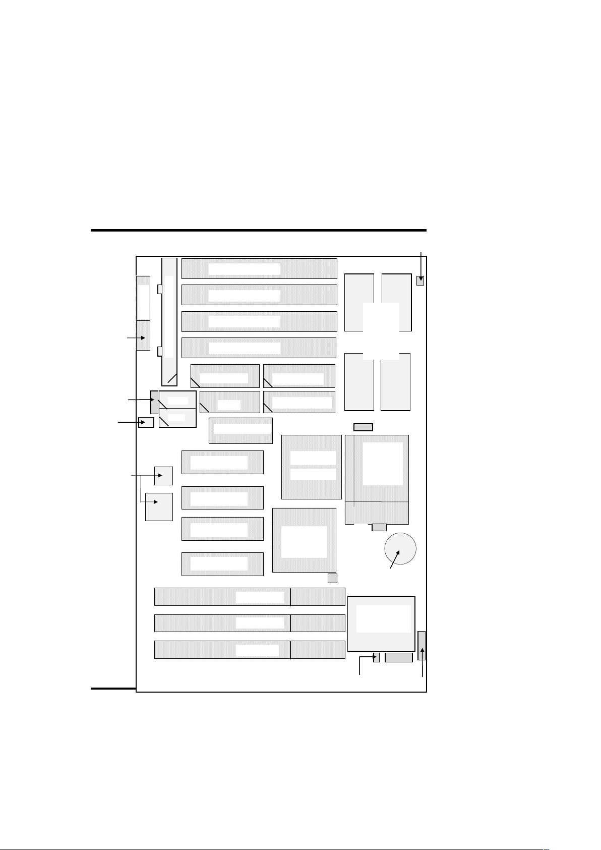
2. INSTALLATION
2-1 Motherboard Layout (Continue…)
Keyboar
SIMM 1 (Bank1)
SIMM 2 (Bank1)
SIMM 3 (Bank0)
SIMM 4 (Bank0)
IDE Primary
LPT1
PCI Slot 1
PCI Slot 2
PCI Slot 3
PCI Slot 4
PCI set
PCI set
ISA Slot 1
ISA Slot 2
ISA Slot 3
IDE Secondary
COM2
Port
Conn.
HDD LED
Port
JP3
JP6
JP2
Power Supply Connector
PS/2
Floppy Drives
IrDA (rear)
Fan
256KB/
512KB
SRAM
USB
ITE
Giga-I/O
COM1
1MB Flash
SB82437VX
SB82371SB
6 EP-PV12 User’s Manual
CPU
ZIF
Socket 7
#CR2032 3.6V
Button Cell Battery
Power
Voltage
IrDA (Front)
Page 12

2. INSTALLATION
2-2 Installation Steps
Page
1. Set Jumpers on the Motherboard 8
2. Install DRAM Memory Modules 9, 10
3. Install the Central Processing Unit (CPU) 11
4. Install the Expansion Cards 12~14
5. Install the External Connectors 15~22
6. Power Up Procedures 23
7. Setup the BIOS software 24
EP-PV12 User’s Manual 7
Page 13

2. INSTALLATION
2-3 Jumpers
Use the diagrams in this manual instead of following the
pin layout on the board. Settings with two jumper numbers
require that both jumpers be moved together. To connect
the pins, simply place a plastic jumper cap over the two
pins as depicted.
1. CPU External Clock Frequency Selection (JP3)
2. CPU Internal Frequency Ratio (JP2)
3. Voltage Regulator Output of CPU Vcore Selection
(JP6)
8 EP-PV12 User’s Manual
Page 14

2. INSTALLATION
2-4 System Memories
This motherboard supports four 72-pin SIMMs (Single
Inline Memory Modules) of 4MB, 8MB, 16MB, 32MB,
64MB to form a memory size between 8MB to 128MB.
The DRAM can be either 60ns or 70ns Fast Page Mode
(FPM, Asymmetric or Symmetric), or Extended Data
Output (EDO). SIMMs must be installed in pairs so that
each bank contains two of the same size memory modules.
Install memory in any or all of the banks an any
combination as follows:
Bank Memory Module
Total
Memory
Bank0
SIMM Slots 1&2
4/8/16/32MB
72-pin FPM, EDO
SIMMs
x 2
Bank1
SIMM Slots 3&4
4/8/16/32MB
72-pin FPM, EDO SIMMs
x 2
Total System Memory =
NOTE: Each bank must have the same size and type
(FPM, EDO, BEDO) of memory installed in pairs.
Memory setup is required “Auto Configuration” in
Chipset Features Setup of the BIOS Software section.
EP-PV12 User’s Manual 9
Page 15

2. INSTALLATION
2-4 System Memories (Continue…)
DRAM Memory Installation Procedures:
1. The SIMM memory modules will only fit in one orientation
as shown because of a “Plastic Safety Tab” on one end of
the SIMM sockets which requires the “Notched End” of
the SIMM memory modules.
2. Press the memory module firmly into place starting from a
45 degree angle making sure that all the contacts are
aligned with the socket.
3. With your finger tips, rock the memory module into a
vertical position so that it clicks into place.
4. The plastic guides should go through the two “Mounting
Holes” on the sides and the “Metal Clips” should snap on
the other side.
5 To release the memory module, squeeze both “Metal Clips”
outwards and rock the module out of the “Metal Clips”.
10 EP-PV12 User’s Manual
Page 16
2. INSTALLATION
2-5 Central Processing Unit (CPU)
The motherboard provides a 321-pin ZIF Socket 7. The
CPU that came with the motherboard should have a fan
attached to it to prevent overheating. If this is not the case
then purchase a fan before you turn on your system. Apply
thermal jelly to the CPU top and then install the fan onto
the CPU.
NOTE: Without a fan, the CPU may overheat and cause
damage to both the CPU and the motherboard
To install a CPU, locate the ZIF socket and open it by first
pulling the lever sideways away from the socket’s “Lock”
then upwards to a 90-degree right angle to insert the CPU
with the correct orientation. You should have a CPU fan that
will cover the surface of the CPU. With the added weight of
the CPU fan, no force is required to insert the CPU. Once
completely inserted, hold down the fan and close the socket’s
lever.
NOTE: You must set the CPU External Clock Frequency
Selection” and “CPU Internal Frequency Ratio”
depending on the CPU that you install.
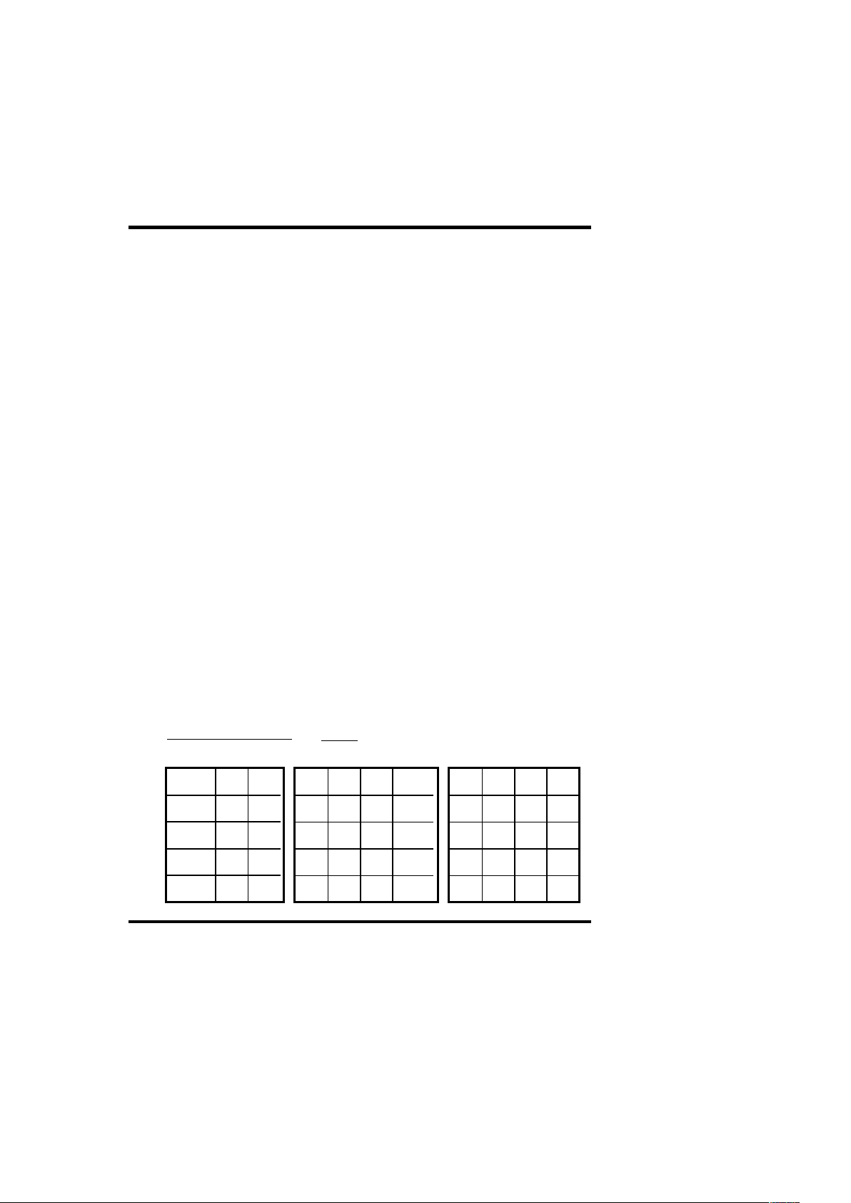
Jumper Settings:
Note:- O-Open, S-Short, X-Don’t Care
JP2
JP6 1-2 3-4
3.52V O O
3.38V O S
2.90V S O
2.80VCS S
1-2 3-4 5-6 MHz
S S X 50
O O X 55
S O X 60
O S X 66
EP-PV12 User’s Manual 11
JP2 1-2 3-4 5-6
2.5 X S S
3 X S O
2 X O S
1.5 X O O
Page 17

2. INSTALLATION
2-6 Expansion Cards
Expansion Card Installation Procedures:
1. Read the documentation for your expansion card.
2. Set any necessary jumpers on your expansion card.
3. Remove your computer system’s cover.
4. Remove the bracket on the slot you intend to use. Keep
the bracket for possible future use.
5. Carefully align the card’s connectors and press firmly.
6. Secure the card on the slot with the screw you removed
in step 4.
7. Replace the computer’s system cover.
8. Setup the BIOS if necessary
9. Install the necessary software drivers for your expansion
card.
Assigning IRQs for Expansion Cards
Some expansion cards need to use IRQ to operate. Generally
an IRQ must be exclusively assigned to one use. In a
standard design there are 16 IRQs available but most of them
are already in use by parts of the system which leaves 6 free
for expansion cards.
12 EP-PV12 User’s Manual
Page 18

2. INSTALLATION
2-6 Expansion Cards (continue…)
Both ISA and PCI expansion cards may need to IRQs. System
IRQs are available to cards installed in the ISA expansion bus
first, and any remaining IRQs are then used by PCI cards.
Currently, there are two types of ISA cards. The original ISA
expansion card design, now referred to as “Legacy” ISA cards,
requires that you configure the card’s jumpers manually and then
install it in any available slot on the ISA bus. You may use
Microsoft’s Diagnostic (MSD.EXE) utility included in Windows
directory to see a map of your used and free IRQs. For Windows
95 users, the “Control Panel” icon in “My Computer”, contains a
“System” icon which gives you a “Device Manager” tab. Double
clicking on a specific device give you “Resource” tab which
shows the Interrupt number and address. Make sure that no two
devices use the same IRQs or your computer will experience
problems when those two devices are in use at the same time.
To simplify this process this motherboard has complied with the
Plug and Play (PnP specification which was developed to allow
automatic system configuration whenever a PnP-compliant card
is added to the system. For PnP cards, IRQs are assigned
automatically from those available.
If the system has both Legacy and PnP ISA card installed, IRQs
are assigned to PnP cards from those not used by Legacy cards.
The PCI and PnP configuration of the BIOS setup utility can be
used to indicate which IRQs are being used by Legacy cards.
For older Legacy cards that does not work with the BIOS, you
can contact your vendor for an ISA Configuration Utility.
An IRQ number is automatically assigned to PCI expansion
cards after those used by Legacy and PnP ISA cards. In the PCI
bus design, the BIOS automatically assigns an IRQ to a PCI slot
that has a card in it that requires an IRQ. To install a PCI card,
you need to set something called the INT (interrupt) assignment.
Since all the PCI slots on this motherboard use an INTA#, be
sure that the jumpers on your PCI cards are set to INTA.
EP-PV12 User’s Manual 13
Page 19

2. INSTALLATION
2-6 Expansion Cards (continue…)
Assigning DMA Channels for ISA Cards
Some ISA cards, both Legacy and PnP may also need to use a
DMA (Direct Memory Access) channel. DMA assignments for
this motherboard are handled the same way as the IRQ
assignment process described above. You can select a DMA
channel in the PCI and PnP configuration section of the BIOS
Setup utility.
NOTE: Choose “Yes” for those IRQ’s and DMA’s you wish
to reserve for Legacy (Non-PnP) ISA expansion cards in
“IRQ xx Used by ISA” and “DMA x Used By ISA” of the
PnP and PCI Setup in the BIOS Software section, otherwise
conflicts may occur.
14 EP-PV12 User’s Manual
Page 20
2. INSTALLATION
2-7 External Connectors
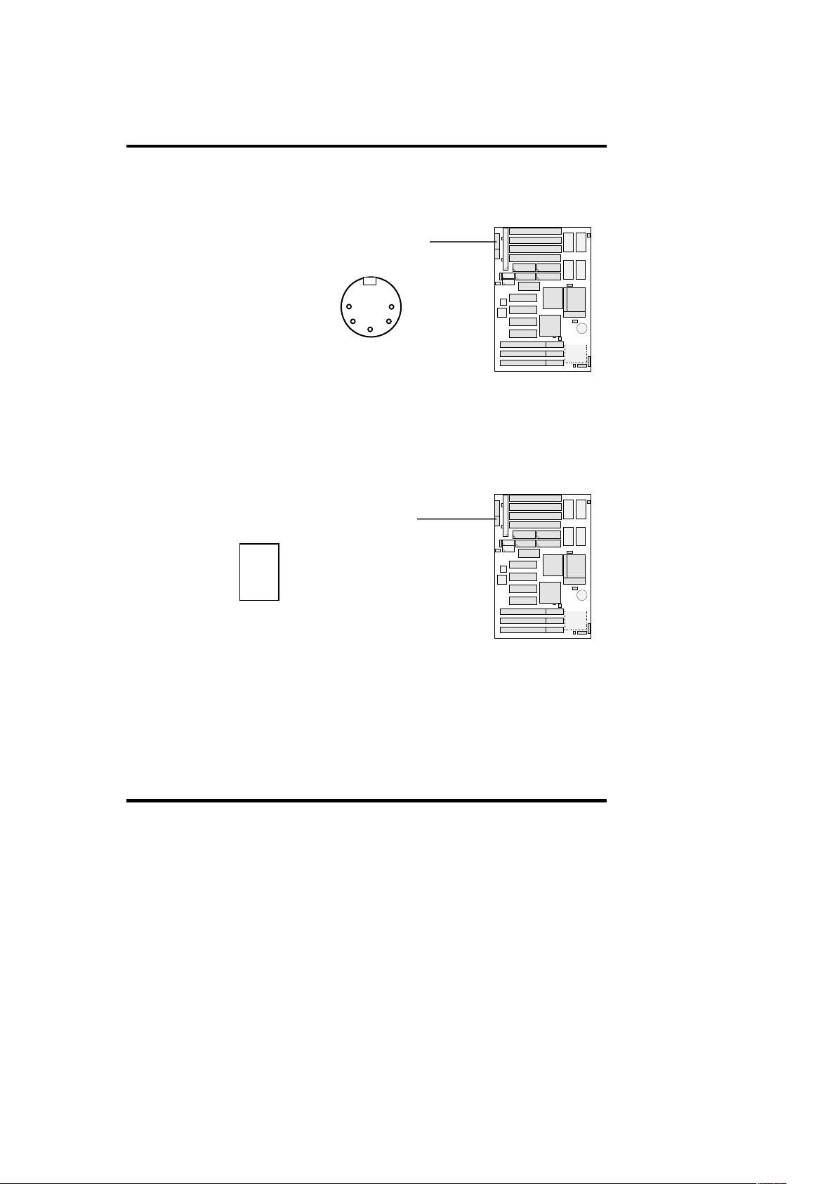
1. AT-Keyboard Connector (5-pin Female)
2. PS/2 Mouse/Keyboard Connector (6-pin Female)
The system will direct IRQ12 to the PS/2 mouse if one is
detected. If not detected, expansion cards can use IRQ12.
See “PS/2 Mouse Control” in BIOS Features Setup of the
BIOS Software.
J2: AT-Keyboard Connector
Up of M/B
J1: PS/2 Mouse Connector
1
EP-PV12 User’s Manual 15
Page 21
2. INSTALLATION
2-7 External Connectors (Continue…)
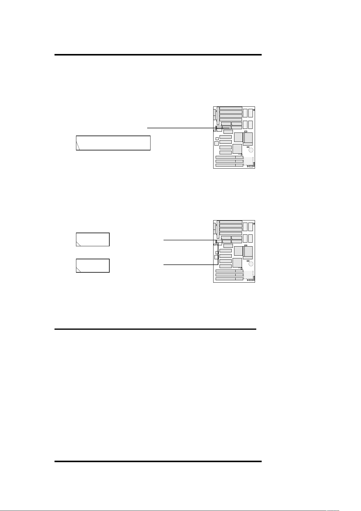
3. Parallel Printer Connector (25-pin Male)
You can enable the parallel port and choose the IRQ
through BIOS Setup on “Onboard Parallel Port” in
“INTEGRATED PERIPHERALS”
4. Serial Port COM1 and COM2 Connectors
(Two 9-pin Male, J5 & J4).
The two serial ports can be used for pointing devices or
other serial devices. See “Onboard Serial Port” in Chipset
Features Setup of the BIOS Software.
2. INSTALLATION
1
J4: COM2
1
1
J5: COM1
16 EP-PV12 User’s Manual
Page 22
2-7 External Connectors (Continue…)
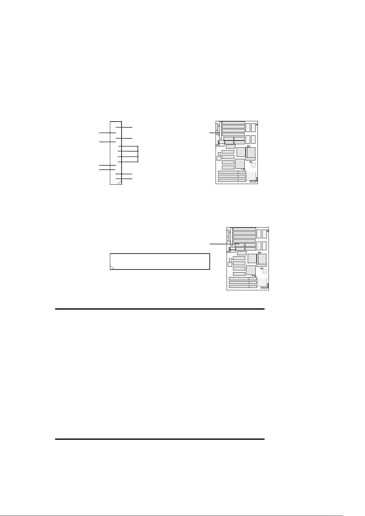
5. AT Power Connector (12-pin block, J3)
NOTE: To prevent electrical spikes, make sure that the
power supply is not connected to an outlet when making or
removing connections. Power supplies contain power
reserves which can damage electrical components.
6. Floppy Drive Connector (34-pin block, J6)
This connector supports the provided floppy drive ribbon cable.
After connecting the single end to the board, connect the
two plugs on the other end to one or two floppy drives.
2. INSTALLATION
2-7 External Connectors (Continue…)
7. Primary/Secondary IDE connectors
Connector
J6: Floppy Drive Connector
1
+5V
<->5V
<->12V
+12V
1
+5V
+5V
GND
+5V
PG
J3: AT Power
EP-PV12 User’s Manual 17
Page 23
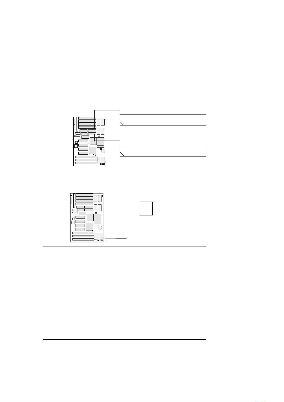
(Two 40-pin Block, J8 & J9)
These connectors support the provided IDE hard disk ribbon
cable. After connecting the single end to the board,
connect the two plugs at the other end to your hard disk(s).
If you install two hard disks, you must configure the
second drive to Slave mode by setting its jumper
accordingly. Please refer to the documentation of your
hard disk for the jumper settings. BIOS now supports IDE
CD-ROM bootup (see “Boot Sequence” in the BIOS
Features Setup of the BIOS Software)
8. IDE (hard disk) Activity LED (JP7)
This connector connects to the IDE (hard disk) activity
indicator light on the system cabinet.
2. INSTALLATION
2-7 External Connectors (Continue…)
9. a) Turbo LED (JP9, pin3 and pin5)
J8: Primary IDE Connector
1
J9: Secondary IDE Connector
1
1
JP7: IDE (hard disk) Activity LED
18 EP-PV12 User’s Manual
+
GND
Page 24
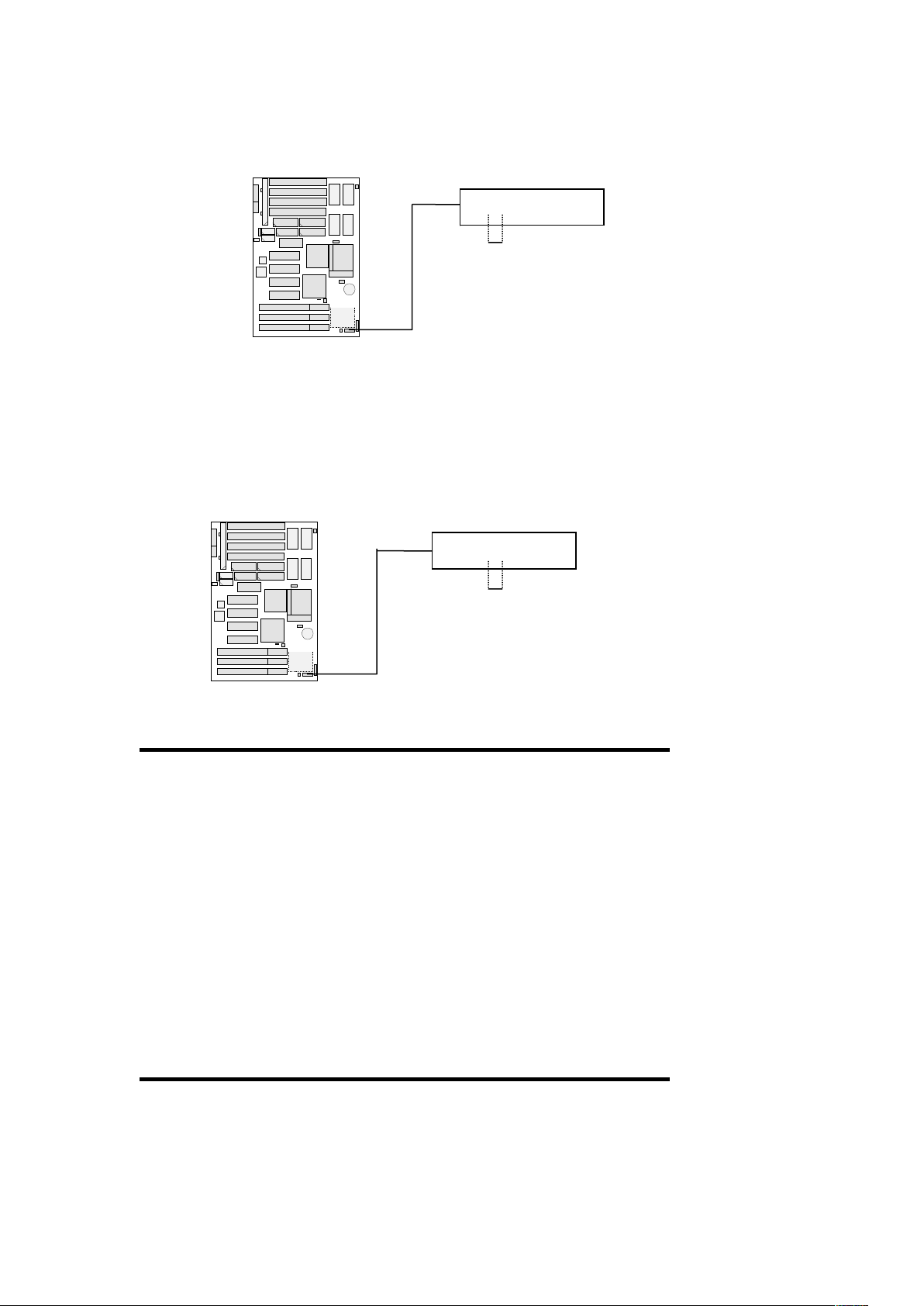
This 2-pin connector lights the Turbo LED when the
motherboard has power.
9. b) SMI Suspend Switch Lead (SMI, pin7 and pin9)
This allows the user to manually place the system into a
suspend mode or “Green” mode where system activity
will be instantly decreased to save electricity and expand
the life of certain components when the system is not in
use.
2. INSTALLATION
2-7 External Connectors (Continue…)
9. c) Reset Switch Lead
(JP9: Short pin17 & pin19, To RESET,)
+
Turbo LED
1
1
JP9: SMI Suspend Switch
GND SMI
EP-PV12 User’s Manual 19
Page 25
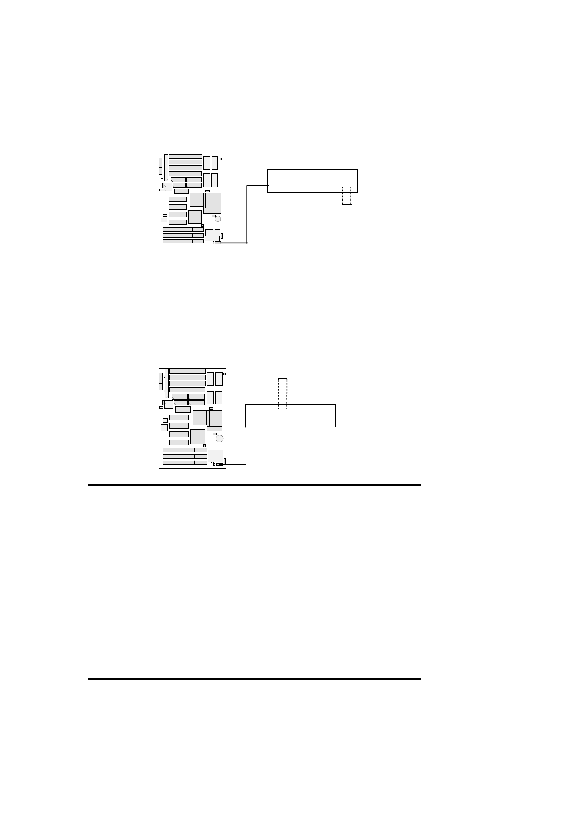
This 2-pin connector connects to the case-mounted reset
switch for rebooting your computer without having to
turn off your power switch. This is a preferred method
of rebooting in order to extend the life of the system’s
power supply.
9. d) Keyboard Lock Switch Lead
(JP9: pin8, pin10, KEYLOCK,)
This 5-pin connector connects to the case-mounted
keyboard lock switch for locking the keyboard and also
to connect the system power LED. The system power
LED lights when the system is powered on.
2. INSTALLATION
2-7 External Connectors (Continue…)
9. e) Speaker Connector
(JP9: pin14 and pin20, SPEAKER)
JP9: Reset Switch Lead
RESET
1
1
JP9: Keyboard Lock Switch
20 EP-PV12 User’s Manual
Page 26
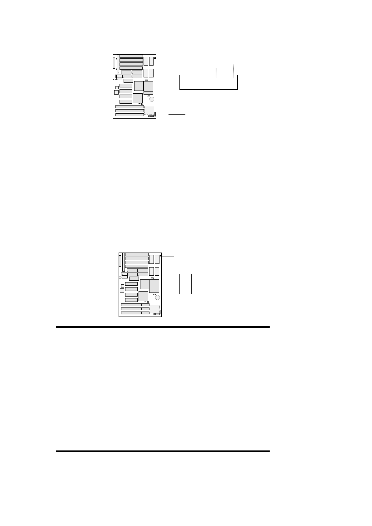
This 2-pin connector connects to the case-mounted speaker.
10. CPU Cooling Fan Connector (JP10)
This connector supports a CPU cooling fan of 500mAmp.
(6Watt) or less. Orient the fan so that the heat sink fins
allow airflow to go across the onboard heat sink(s)
instead of the expansion slots. Depending on the fan
manufacturer, the wiring and plug may be different. The
red wire should be positive, while the black should be
ground. Connect the fan’s plug to the board taking into
consideration the polarity of the connector.
NOTE:The CPU and/or motherboard will overheat if
there is no airflow across the CPU and onboard heat
sinks. Damage may occur to the motherboard and/or the
CPU fan if these pins are incorrectly used. These are not
jumpers, do not place jumper caps over these pins.
2. INSTALLATION
2-7 External Connectors (Continue…)
11. IrDA-Compliant Infrared Module Connector
Speaker Connector
1
JP9 (pin14, pin20):
JP10: CPU Cooling Fan
Connector
1
EP-PV12 User’s Manual 21
Page 27
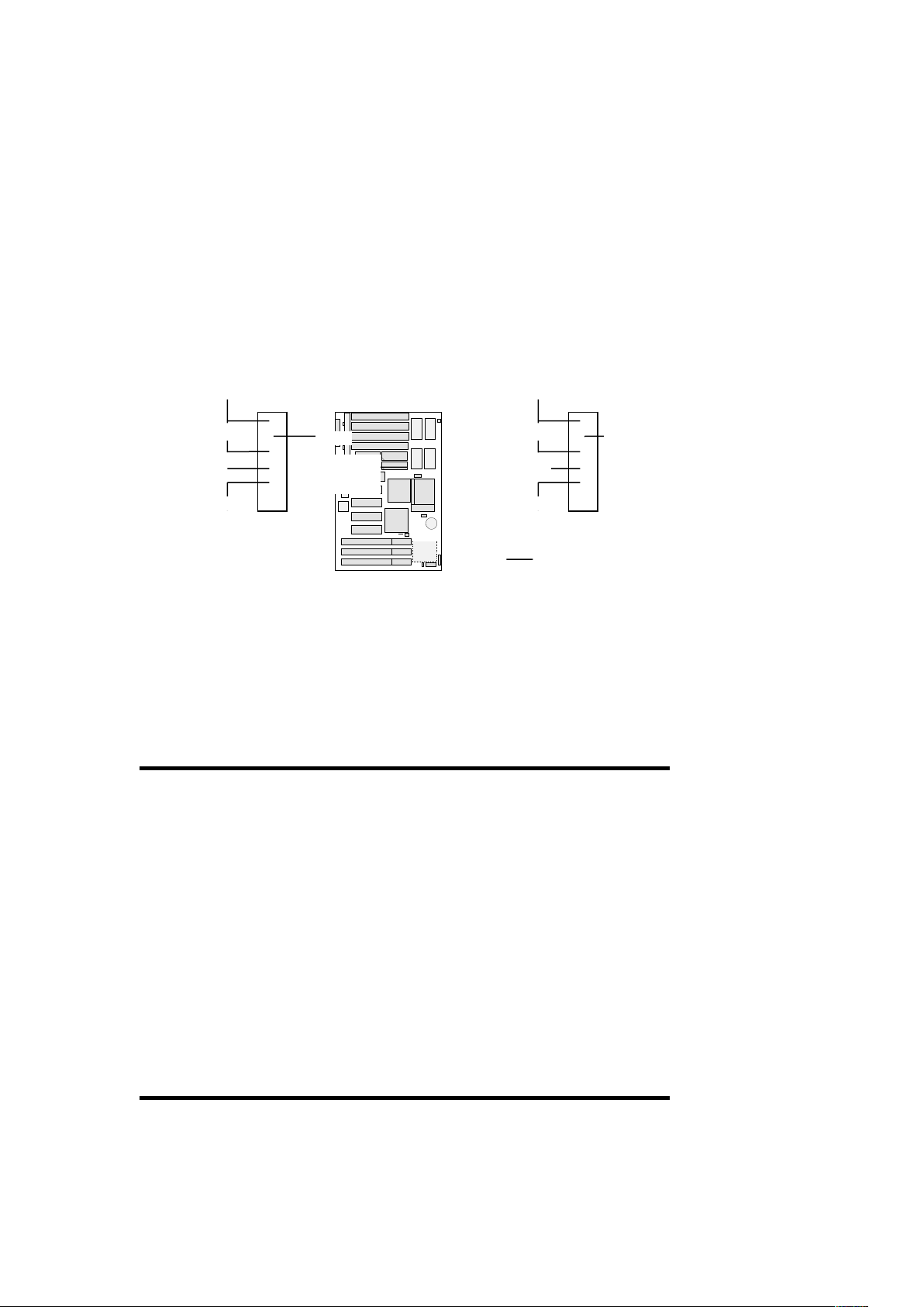
(JP4, JP11)
This connector supports the optional wireless transmitting
and receiving infrared module. This module mounts to a
small opening on system cases that support this feature.
You must also configure UART 2 Use Infrared in Chipset
Features Setup to select whether UART2 is directed for
use with COM2 or IrDA. When IrDA is selected in
BIOS, COM2 will be disabled. Use the six pins as shown
on the Back View and connect a ribbon cable from the
module to the motherboard to the pin definitions.
2. INSTALLATION
2-8 Power Up Procedures
1. After jumpers and connections are made, close the system
case cover.
IrDA (rear)
KyBd Power
IRRX
GND
IRTX
KEY
VCC
IRRX
GND
IRTX
KEY
1
JP4:
22 EP-PV12 User’s Manual
1
JP11:
IrDA (front)
Page 28

2. Make sure that all switches are in the off position.
3. Connect the power supply cord into the supply located on
the back of your system case as instructed by your system
user’s manual.
4. Connect the power cord outlet that is equipped by a surge
protector.
5. You may turn on your devices in the following order:
a. Your monitor
b. Your system power. For power supplies, you need to
switch on the power supply as well as press the power
switch on the front of the case.
6. During power-on, hold down the <Del> key to enter BIOS
setup. Follow the next section “BIOS” SOFTWARE” for
instructions.
Powering Off your computer: You must first exit or
shut down your operating system before switching off
the power switch.
3. BIOS SOFTWARE
3-1 Introduction
AWARD BIOS ROM provides a built-in setup program that
allows users to modify the basic system configuration and
hardware parameters. The modified data will be stored in a
battery-backed CMOS RAM so data will be retained even when
EP-PV12 User’s Manual 23
Page 29

the power is turned off. In general, the information saved in the
CMOS RAM stay unchanged unless there is configuration
change in the system, such as hard drive replacement or new
equipment change.
It is possible that CMOS had a battery failure which cause data
lose in CMOS RAM. If so, re-enter system configuration
parameters become necessary.
The Award BIOS is immediately activated when you first power
on the computer. The BIOS reads the system information
contained in the CMOS and begins the process of checking out
the system and configuring it. When it finishes, the BIOS will
seek an operating system on one of the disks and then launch and
turn control to the operating system.
While the BIOS is in control, the Setup program can be activated
in one of the two ways:
1. By pressing <Del> immediately after switching system on, or
2. by pressing the <Del> key when the following message
appears briefly at the bottom of the screen during the POST
(Power On Self Test). Press <Del> to enter SETUP.
If the message disappears before you respond and you still wish
to enter Setup, restart the system to try again by turning it OFF
then ON or pressing the “RESET” button on the system case.
You may also restart by simultaneously pressing <Ctrl>, <Alt>,
and <Del> keys. If you do not press the keys at the correct time
and the system does not boot, an error message will be displayed
and you will again asked to …
PRESS <F1> TO CONTINUE, <Del> TO ENTER SETUP
3. BIOS SOFTWARE
3-2 AWARD BIOS Setup Program
To turn on (or reboot) the system and press the [Del] key to
enter the AWARD BIOS setup screen as following:
24 EP-PV12 User’s Manual
Page 30

ROM PCI/ISA BIOS (2A59GECA)
CMOS SETUP UTILITY
AWARD SOFTWARE, INC
STANDARD CMOS SETUP INTEGRATED PERIPHERALS
BIOS FEATURES SETUP SUPERVISOR PASSWORD
CHIPSET FEATURES SETUP USER PASSWORD
POWER MANAGEMENT SETUP IDE HDD AUTO DETECTION
PNP/PCI CONFIGURATION HDD LOW LEVEL FORMAT
LOAD BIOS DEFAULTS SAVE & EXIT SETUP
LOAD SETUP DEFAULTS EXIT WITHOUT SAVING
ESC : Quit : Select Item
F10 : Save & Exit Setup (Shift) F2 : Change Color
Time, Date, Hard Disk Type…
Figure 3-1 CMOS Setup Utility Screen
Once you enter the Award BIOS CMOS Setup Utility, the
Main Menu will appear on the screen. The Main Menu allows
you to select from several setup functions and two exit choices.
Use the arrow keys to select among the items and press
<Enter> to accept the sub-menu.
3. BIOS SOFTWARE
3-3 Standard CMOS SETUP
To choose the “STANDARD CMOS SETUP” option from the
CMOS SETUP UTILITY Menu ( Figure 3-2) and the screen
below is displayed. This standard Setup Menu allows users to
configure system components such as date, time, hard disk
EP-PV12 User’s Manual 25
Page 31
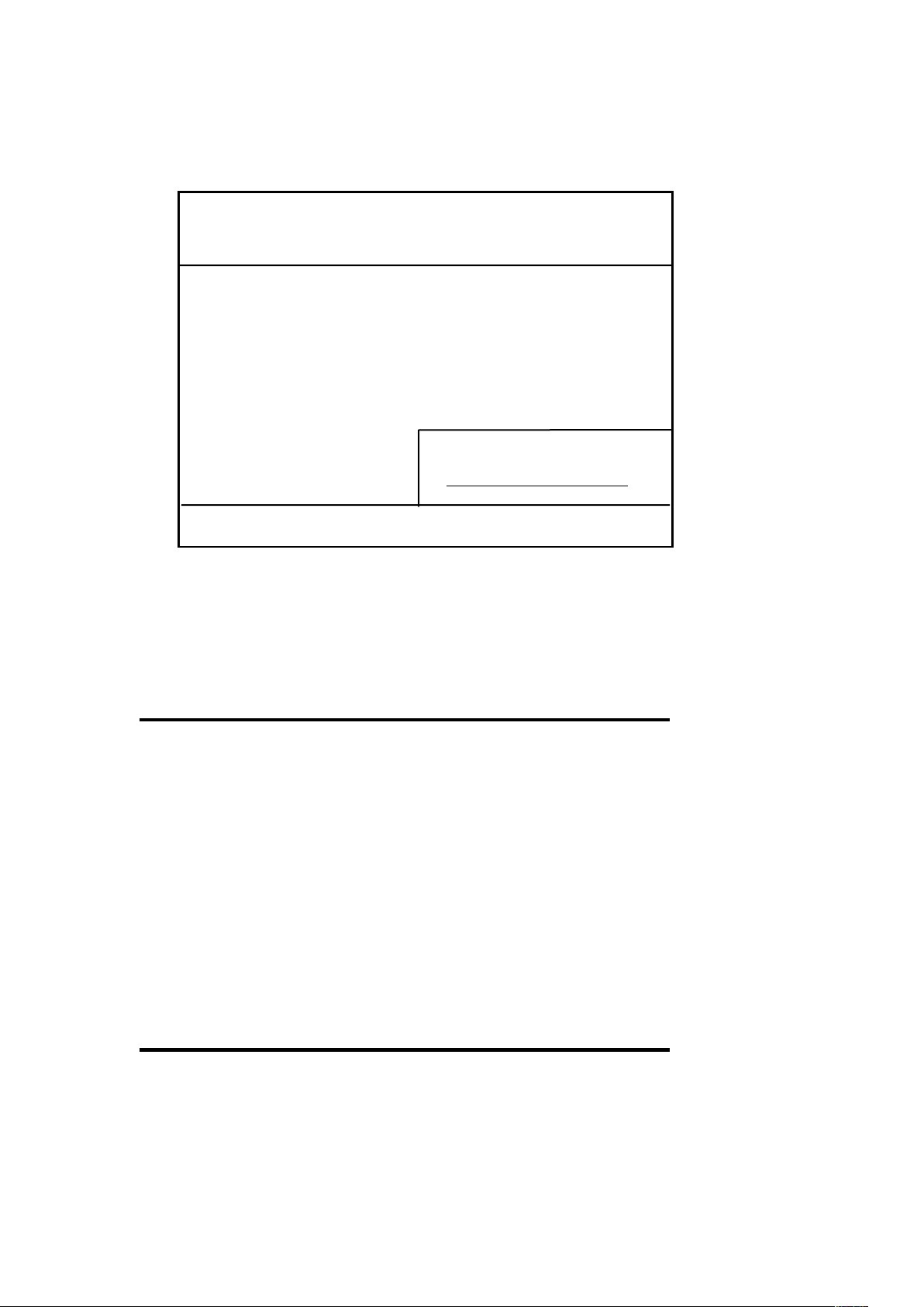
drive, floppy disk drive, display and memory. When a field is
highlighted, on-line help information is displayed in the left
bottom of the Menu screen.
ROM PCI/ISA BIOS (2A59GECA)
STANDARD SETUP UTILITY
AWARD SOFTWARE, INC
Date (mm: dd: yy): Fri, Jan 31 1997
Time (hh:mm:ss) : 9 : 15 : 41
HARD DISKS TYPE SIZE CYLS HEAD PRECOMP LANDZ SECTOR MODE
Primary Master : Auto 0 0 0 0 0 0 LBA
Primary Slave : Auto 0 0 0 0 0 0 AUTO
Secondary Master : Auto 0 0 0 0 0 0 AUTO
Secondary Slave : Auto 0 0 0 0 0 0 AUTO
Drive A : 1.44M, 3.5in. Base Memory: 640K
Drive B : None Extended Memory: 31744K
Video : EGA/VGA Other Memory: 384K
Halt On : All Errors Total Memory: 32768K
ESC : Quit : Select Item PU/PD/+/- : Modify
F1 : Help (Shift) F2 :Change Color
Figure 3-2 Standard CMOS Setup Screen
Hard Disk Mode: Install hard disk (such as MFM, ESDI or
IDE) to your system, you need to have their specifications
recorded here. The SCSI drives operate using device drivers
and are not supported directly by BIOS.
For IDE hard drives, the BIOS provides three modes to support
both normal IDE hard disks and also drives larger than 528MB.
3. BIOS SOFTWARE
3-3 Standard CMOS SETUP (Continue..)
Normal Mode - for IDE drives smaller than 528MB.
LBA Mode - provide LBA (Large Block Addressing) function
for mass capacity hard disk that is larger than 528MB and up to
26 EP-PV12 User’s Manual
Page 32

8.4GB (Giga-Bytes).
Large Mode - doesn’t use LBA function for above mass
capacity hard disk. Large mode is new specifications which
may not be fully supported by all operational systems (MSDOS is OK right now, but is uncommon).
*Write Pre-Compensation - The size of a sector gets
progressively smaller as the track diameter diminishes. Yet
each sector must still hold 512 bytes. Write pre-compensation
circuitry on the hard disk compensates for the physical
difference in sector size by boosting the write current sectors
on inner track.
* Landing Zone - The cylinder location where the heads will
normally park when the system is shut down.
* Capacity = (Number of heads) x (Number of cylinders) x
(Number of sectors per track) x (512 Bytes per sector)
3. BIOS SOFTWARE
3-4 BIOS Features Setup
By choosing the “BIOS FEATURES SETUP” option from the
CMOS SETUP UTILITY Menu, the screen below is displayed.
This sample screen contains the manufacturer’s default values for
the motherboard.
EP-PV12 User’s Manual 27
Page 33

ROM PCI/ISA BIOS (2A59GECA)
BIOS FEATURES SETUP
AWARD SOFTWARE, INC
Virus Warning : Disabled Video BIOS Shadow : Enabled
CPU Internal Cache : Enabled C8000 - CBFFF Shadow : Disabled
External Cache : Enabled CC000 - CFFFF Shadow : Disabled
Quick Power On Self Test : Disabled D0000 - D3FFF Shadow : Disabled
Boot Sequence : A,C,SCSI D4000 - D7FFF Shadow : Disabled
Swap Floppy Drive : Disabled D8000 - DBFFF Shadow : Disabled
Boot Up Floppy Seek : Enabled DC000 - DFFFF Shadow : Disabled
Boot Up NumLock Status : ON
Boot Up System Speed : High
Gate A20 Option : Fast
Typematic Rate Setting : Disabled
Typematic Rate (Chars/Sec) : 6
Typematic Delay (Msec) : 250
Security Option : Setup
PCI/VGA Palette Snoop : Disabled ESC : Quit : Select Item
OS Select For DRAM>64MB : Non-OS2 F1 : Help PU/PD/+/- : Modify
Report No FDD for WIN95 : Yes F5 : Old Values (Shift) F2 : Color
F6 : Load BIOS Defaults
F7 : Load Setup Defaults
Figure 3-3 BIOS Feature Setup Screen
a. Virus Warning
When enabled, BIOS warns the user when any program
attempts to write or format the boot sector and allows the user
to intervene.
b. Cache Control
CPU Internal Cache/External Cache: These two categories
speed up memory access. The default value is enable.
3. BIOS SOFTWARE
3-4 BIOS Features Setup (Continue…)
c. Boot Up Features
After power on the system, BIOS will perform a series of
device initializations and diagnostic tests.
Quick Power On Self Test: If it set to Enabled, BIOS will
skip some check items during POST.
28 EP-PV12 User’s Manual
Page 34

d. Boot Sequence
This option sets the sequence of boot drives (either floppy drive A:
or hard disk drive C that BIOS attempts to boot from after
POST completes.
CD-ROM driver is becoming a standard device on computer
systems. It has a large storage capacity advantage to store different
operating system on it and will need boot-up of the system via CDROM. Now, we provides CD-ROM boot-up function that allows
the user to select booting from drive A, C, or CD-ROM. No matter
if the CD-ROM is IDE or SCSI, the system will look for the first
available bootable device for the operating system.
Swap Floppy Drive: Enabled - The system will swap the floppy
drive assignment so that drive A will function as drive B, drive B
will function as drive A.
Boot Up Floppy Seek: During POST, BIOS will determine if the
floppy disk drive installed is 40 or 80 tracks. (360K type drive is
40 tracks and the 720K, 1.2M and 1.44M are 80 tracks).
Boot Up NumLock Status: Define the keyboard as number keys
or arrow keys.
Boot-Up System Speed: This option selects the speed of CPU at
system boot time.
e. Keyboard Interface
Typematic Rate Setting: When enabled, you can set the two
typematic controls listed next, default setting is “Disabled”.
3. BIOS SOFTWARE
3-4 BIOS Features Setup (Continue…)
Typematic Rate (chars/sec): The typematic rate is set at the
rate at which characters on the screen repeat when a key is
pressed and held down.
Typematic Delay (msec): Choose how long after you press a
EP-PV12 User’s Manual 29
Page 35

key that a character begins repeating.
f. Security Option
System: When entering wrong password, the system will not
boot and deny to access the BIOS setup.
Setup: When entering wrong password, the system can boot,
but deny any access to the BIOS Setup.
g. PCI/VGA Palette Snoop
A system may have two display devices present in the system:
a VGA-compatible interface and another graphics controller.
In this case, both devices implement the color palette registers
at the same I/O addresses. The configuration software must
program on of the devices to actively act as the target, while
the other device is programmed to quietly “snarf” the write
data form the bus as it flies by on its way to the other device.
Some non-standard VGA cards or MPEG video cards may
not show colors properly. You can leave this setting to
Enable that could correct this problem.
h. OS Select (For DRAM > 64MB)
If your system DRAM is larger than 64MB and running OS/2,
please select “OS/2” as the item value. If running other
operating system, please set the item value to “non-OS/2”.
i. Report No FDD for Win95
Under Win95 system, allow the releasing of FDD port’s
IRQ for other usage.
j. Shadow Memory
BIOS can copy adapter’s ROM from address C0000h through
DFFFFh to RAM for faster execution. Shadow setting are
chipset specific and dependent on system hardware.
3. BIOS SOFTWARE
3-5 Chipset Features Setup
By choosing the “CHIPSET FEATURES SETUP” option from
30 EP-PV12 User’s Manual
Page 36

the CMOS SETUP UTILITY Menu, the screen below is
displayed. This sample screen contains the manufacturer’s
default values for the motherboard.
ROM PCI/ISA BIOS (2A59GECA)
CHIPSET FEATURES SETUP
AWARD SOFTWARE, INC
AUTO Configuration : Enabled Delay Transaction : Disabled
DRAM Timing : 70ns
DRAM RAS# Precharge Time : 4
DRAM R/W Leadoff Timing : 6
Fast RAS to CAS Delay : 3
DRAM Read Burst (EDO/FPM) : x333/x444
DRAM Write Burst Timing : x333
Fast MA to RAS# Delay Clk : 1
Fast EDO Path Select : Disabled
Refresh RAS# Assertion : 5 Clks
ISA Bus Clock : PCICLK/4
System BIOS Cacheable : Disabled
Video BIOS Cacheable :Disabled
8 Bit I/O Recovery Time : N/A ESC : Quit : Select Item
16 Bit I/O Recovery Time : 1 F1 : Help PU/PD/+/- : Modify
Memory Hole At 15M-16M : Disabled F5 : Old Values (Shift) F2 : Color
Peer Concurrency : Enabled F6 : Load BIOS Defaults
Passive release : Enabled F7 : Load Setup Defaults
Figure 3-4 BIOS Chipset Features Setup Screen
a. 8-bit I/O Recovery Time & 16-bit I/O Recovery Time
This category is used to add additional recovery delay
between CPU or PCI master 8-bit (or 16-bit) I/O cycles to the
ISA Bus. The options are 1 to 8 and N/A.
b. IDE HDD Block Mode: Enabled/Disabled
Specifies the maximum number of sectors that can be
transferred at a time.
c. Memory Hole at 15MB-16MB: Enabled/Disabled
In order to improve performance, certain space in memory
can be reserved for ISA cards. This memory must be mapped
into the memory space below 16 MB.
3. BIOS SOFTWARE
3-6 Power Management Setup
EP-PV12 User’s Manual 31
Page 37

This section provides information of functioning the Green PC
power management features. For enabling the power
management function, please select “POWER
MANAGEMENT SETUP” option from the “CMOS SETUP
UTILITY” Menu.
ROM PCI/ISA BIOS (2A59GECA)
POWER MANAGEMENT SETUP
AWARD SOFTWARE, INC
Power Management : Disabled ** Power Down & Resume Events **
PM Control by APM : Yes IRQ3 (COM2) : On
Video Off Method : V/H SYNC+Blank IRQ4 (COM1) : On
Modem use IRQ : 3 IRQ5 (LPT2) : Off
Doze Mode : Disabled. IRQ6 (Floppy Disk) : Off
Standby Mode : Disabled IRQ7 (LPT1) : Off
Suspend Mode : Disabled IRQ8 (RTC Alarm) : Off
HDD Power Down : Disabled IRQ9 (IRQ2 Redir) : Off
** Wake up Events In Doze & Standby ** IRQ10 (Reserved) : Off
IRQ3 (Wake-Up Event) :On IRQ11(Reserved) : Off
IRQ4(Wake-Up Event) :On IRQ12 (PS/2 Mouse) : Off
IRQ8(Wake-Up Event) :On IRQ13(Coprocessor) : Off
IRQ12 (Wake-Up Event) :On IRQ14(Hard Disk) : On
IRQ15(Reserved) : Off
ESC : Quit :Select Item
F1 : Help PU/PD/+/- : Modify
F5 : Old Values (Shift) F2 : Color
F6 : Load BIOS Defaults
F7 : Load Setup Defaults
Figure 3-5 Power Management Setup Screen
a. Selecting “Power Management” Mode
Power Management
User Define - User can configure their own power
management function.
Disabled - Disable the power management features.
Minimum Saving - All timers are in their minimum value.
Doze - One hour; Standby, One hour; Suspend, One hour.
Maximum Saving - All timers are in their maximum value.
Doze - One hour; Standby, One hour; Suspend, One hour.
3. BIOS SOFTWARE
3-6 Power Management Setup (Continue…)
PM Control by APM
32 EP-PV12 User’s Manual
Page 38

Support the Intel and Microsoft INT 15h Advanced Power
Management BIOS function which creates and interface to allow
the OS to communicate with the SIMM code. If APM is not in
stalled, this option has no effect.
APM(Advanced Power Management) should be installed to
keep the time updated when the computer enters suspend
mode activated by the BIOS Power Management, For DOS
environments, you need to add DEVICE=C:\DOS\
POWER.EXE. For Windows 3.1x and Windows 95, you
need to install Windows using the APM feature.
Video Off Method
Blank - BIOS will only blanks off the screen when disabling
video.
V/H SYNC+Blank - BIOS will blank off the screen and turn off
V/H SYNC signals to turn off the V-SYNC and H-SYNC signals
from VGA cards to monitor.
If Green monitors detect the V/H-SYNC signals turned off,
it cuts off the electron gun to save power consumption.
b. PM Time Setting
Doze Mode: If no PM events happened and the Doze timer
expires, system will enter CPU’s Doze mode.
Standby Mode: If system runs into Doze mode and the
Standby timer expires, system will enter CPU’s Standby
mode (CPU speed = CPUCLK / 3 MHz) from Doze mode.
The CPUCLK (external CPU clock) means system clock
mentioned in the manual.
Suspend Mode: If there is no any activity continued and the
Suspend is time-out, the system will stop the CPU clock (CPU
speed = 0 MHz).
Within Standby or Suspend, system may also turn off the
video signal and power down the hard disk driver (depend on
“HDD Power Down” setting).
3. BIOS SOFTWARE
3-6 Power Management Setup (Continue…)
HDD Power Down: When the HDD idle time has elapsed, the
EP-PV12 User’s Manual 33
Page 39

BIOS sends a command to the hard disk to enter sleep mode
(turn off the motor). This function is only valid for IDE HDDs
that support power saving function.
c. PM Events Mask Control
Individual IRQ Wake-Up Event: If an interrupt request is
generated by using a device, it will wake up the system to
normal mode (support by any green modes).
Power Down Activities:
The system runs at Doze at Suspend Mode:
If any event happened, the system will return to normal mode.
The system runs at Doze or Standby mode:
If any event happened, the timer will recounting from zero.
APM(Advanced Power Management) should be installed to
keep the time updated when the computer enters suspend
mode activated by the BIOS Power Management, For DOS
environments, you need to add DEVICE=C:\DOS\
POWER.EXE. For Windows 3.1x and Windows 95, you
need to install Windows using the APM feature.
Video Off Method
Blank - BIOS will only blanks off the screen when disabling
video.
V/H SYNC+Blank - BIOS will blank off the screen and turn off
V/H SYNC signals to turn off the V-SYNC and H-SYNC signals
from VGA cards to monitor.
If Green monitors detect the V/H-SYNC signals turned off,
it cuts off the electron gun to save power consumption.
3. BIOS SOFTWARE
3-7 PCI/PNP & Onboard I/O Setup
34 EP-PV12 User’s Manual
Page 40

The PNP/PCI configuration program is for the user to modify
the PCI/ISA IRQ signals when various PCI/ISA cards are
inserted in the PCI or ISA slots.
WARNING: Any misplacing IRQ could cause system can’t
pick out the resources.
ROM PCI/ISA BIOS (2A59GECA)
PNP/PCI CONFIGURATION
AWARD SOFTWARE, INC
Resources Controlled by : Manual PCI IRQ Activated by : Level
Reset Configuration Data : Disabled PCI IDE IRQ Map To : PCI-AUTO
Primary IDE INT# : A
IRQ-3 Assigned to : Legacy ISA Secondary IDE INT# : B
IRQ-4 Assigned to : Legacy ISA
IRQ-5 Assigned to : PCI/ISA PnP Used MEM Base Addr : N/A
IRQ-7 Assigned to : PCI/ISA PnP
IRQ-9 Assigned to : PCI/ISA PnP
IRQ-10 Assigned to : PCI/ISA PnP
IRQ-11 Assigned to : PCI/ISA PnP
IRQ-12 Assigned to : PCI/ISA PnP
IRQ-14 Assigned to : PCI/ISA PnP
IRQ-15 Assigned to : PCI/ISA PnP
DMA-0 Assigned to : PCI/ISA PnP
DMA-1 Assigned to : PCI/ISA PnP
DMA-3 Assigned to : PCI/ISA PnP ESC : Quit : Select Item
DMA-5 Assigned to : PCI/ISA PnP F1 : Help PU/PD/+/- : Modify
DMA-6 Assigned to : PCI/ISA PnP F5 : Old Values (Shift) F2 : Color
DMA-7 Assigned to : PCI/ISA PnP F6 : Load BIOS Defaults
F7 : Load Setup Defaults
Figure 3-6 PNP/PCI Configuration Setup Screen
a. Resource Controlled By: The default value is Manual.
Manual: The field defines that the PnP card’s resource is
controlled by manual . You can set which IRQ-X and DMA-X
assigned to PCI/ISA PnP or Legacy ISA cards.
Auto: If your ISA card and PCI card are all PnP cards. To
set this field code. If Advanced Power Management (APM) is
not installed, this option has no effect.
3. BIOS SOFTWARE
3-7 PCI/PNP & Onboard I/O Setup (Continue..)
EP-PV12 User’s Manual 35
Page 41
b. Reset Configuration Data: The default value is Disabled.
Disabled: Normal Setting.
Enabled: If you have plugged some Legacy cards in the
system and there were recorded into ESCD (Extended
System Configuration Data). You can set this field to
Enabled and to clear ESCD one time. When some Legacy
cards were removed.
c. PCI IDE IRQ Map To: The default value is PCI-AUTO.
When you have true PCI card(s) plugged into the system, you
will not need to change anything here in the SETUP program.
However, if you do not know whether you have true PCI card
or not, please refer to your PCI card user’s manual for the
detail.
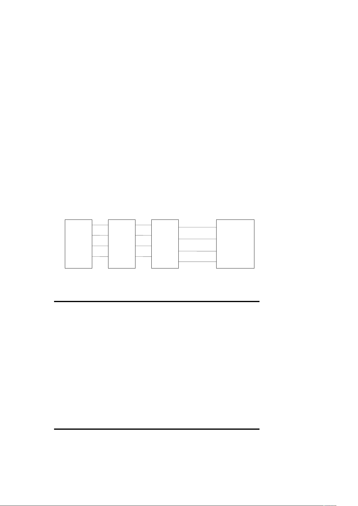
When you have Legacy card plugged into the system, a
proper setting is extremely important or it may cause the
system to hang up. The diagram below shows how the
Rotating Priority Mechanism is designed.
PCI#3 PCI#2 PCI#1
PIRQ0 PIRQ1 PIRQ2
PIRQ1 PIRQ2 PIRQ3 PCI
PIRQ2 PIRQ3 PIRQ0 INTC Chipset
PIRQ3 PIRQ0 PIRQ1 INTD
Figure 3-7 The Combination of PCI INT# Lines
3. BIOS SOFTWARE
3-8 Integrated Peripherals
Note: If you don’t use the Onboard IDE connector, than use
On-card (PCI or ISA card) IDE connector, you will set
INTB
36 EP-PV12 User’s Manual
Page 42

Onboard Primary PCI IDE: Disabled and Onboard Secondary
PCI IDE: Disabled from CHIPSET FEATURES SETUP
UTILITY. The Onboard PCI IDE cable should be equal to or
less than 18 inches (45cm).
ROM PCI/ISA BIOS (2A59GECA)
INTEGRATED PERIPHERALS
AWARD SOFTWARE, INC
IDE HDD Block Mode :Enabled
IDE Primary Master PIO :Auto
IDE Primary Slave PIO :Auto
IDE Secondary Master PIO :Auto
IDE Secondary Slave PIO :Auto
On-Chip Primary PCI IDE : Enabled
On-Chip Secondary PCI IDE : Enabled
PCI Slot IDE 2nd Channel : Enabled
USB Controller : Enabled
USB Keyboard Support : Disabled
KBC Input Clock : 12MHz
Onboard FDC Controller : Enabled
Onboard Serial Port1 : Auto ESC : Quit : Select Item
Onboard Serial Port2 : Auto F1 : Help PU/PD/+/- : Modify
UR2 Mode : Standard F5 : Old Values (Shift) F2 : Color
Onboard Parallel Port :378/IRQ7 F6 : Load BIOS Defaults
Parallel Port Mode : SPP F7 : Load Setup Defaults
Figure 3-8 Integrated Peripherals Setup Screen
a. Resource Controlled By: The default value is Manual.
Manual:The field defines that the PnP card’s resource is
controlled by manual . You can set which IRQ-X
and DMA-X assigned to PCI/ISA PnP or Legacy
ISA cards.
Auto: If your ISA card and PCI card are all PnP cards. To
set this field code. If APM is not installed, this
option has no effect.
3. BIOS SOFTWARE
3-8 Integrated Peripherals (Continue…)
b. Onboard Primary PCI IDE: The default value is
Enabled.
EP-PV12 User’s Manual 37
Page 43

Enabled: Enable Onboard 1st channel IDE port.
Disabled: Disable Onboard 1st channel IDE port. When
use On-card (PCI or ISA card) IDE connector.
c. Onboard Primary PCI IDE: The default value is
Enabled.
Enabled: Enable Onboard 1st channel IDE port.
Disabled: Disable Onboard 1st channel IDE port. When
use On-card (PCI or ISA card) IDE connector.
d.IDE Primary Master PIO: The default value is Auto.
Auto: BIOS will automatically detect the Onboard
Primary Master PCI IDE HDD Accessing
mode.
Mode 0-4: Manually set the IDE Accessing mode.
e.IDE Primary Slave PIO: The default value is Auto.
Auto: BIOS will automatically detect the Onboard
Primary Slave PCI IDE HDD Accessing
mode.
Mode 0-4: Manually set the IDE Accessing mode.
f. IDE Secondary Master PIO: The default value is Auto.
Auto: BIOS will automatically detect the Onboard
Secondary Master PCI IDE HDD Accessing
mode.
Mode 0-4: Manually set the IDE Accessing mode.
g.IDE Secondary Slave PIO: The default value is Auto.
Auto: BIOS will automatically detect the Onboard
Secondary Slave PCI IDE HDD Accessing
mode.
Mode 0-4: Manually set the IDE Accessing mode.
3. BIOS SOFTWARE
3-8 Integrated Peripherals (Continue…)
h. Onboard FDC Controller: The default value is Enabled.
Enabled: Enable the Onboard I/O CHIP’s floppy drive
interface controller.
38 EP-PV12 User’s Manual
Page 44

Disabled: Disable the Onboard I/O CHIP’s floppy drive
interface controller. When use On-card ISA
card FDC’s controller.
i. Onboard UART 1:
This field allows the user to select the serial port. The default
value is 3F8H/IRQ4.
COM1: Enable Onboard Serial Port 1 and address is 3F8H/IRQ4.
COM2: Enable Onboard Serial Port 1 and address is 2F8H/IRQ3.
COM3: Enable Onboard Serial Port 1 and address is 3E8H/IRQ4.
COM4: Enable Onboard Serial Port 1 and address is 2E8H/IRQ4.
Disabled: Disable Onboard I/O CHIP’s serial port 1.
j. Onboard UART 2:
This field allows the user to select the serial port. The default
value is 2F8H/IRQ3.
COM1: Enable Onboard Serial Port 2 and address is 3F8H/IRQ4.
COM2: Enable Onboard Serial Port 2 and address is 2F8H/IRQ3.
COM3: Enable Onboard Serial Port 2 and address is 3E8H/IRQ4.
COM4: Enable Onboard Serial Port 2 and address is 2E8H/IRQ4.
Disabled: Disable Onboard I/O CHIP’s serial port 2.
k.Onboard UART 2 Mode: The default value is standard.
This field allows the user top select the COM2 port that can
support a serial Infrared Interface.
HPSIR: Support a Serial Infrared Interface IrDA.
ASKIR: Support a HP Serial Infrared Interface formats.
l. Onboard Parallel Port: This field allows the user to select
the LPT port. The default value is 378H/IRQ7.
378H: Enable Onboard LPT port and address is 378H and IRQ7.
278H: Enable Onboard LPT port and address is 278H and IRQ5.
3BCH: Enable Onboard LPT port and address is 3BCH and IRQ7.
Disabled: Disabled Onboard SMC CHIP’s LPT port.
3. BIOS SOFTWARE
3-8 Integrated Peripherals (Continue…)
Note: Parallel Port address is 378H/3BCH that selects the routing
of IRQ7 for LPT1. Parallel Port address is 278H that select the
routing of IRQ5 for LPT1.
EP-PV12 User’s Manual 39
Page 45

n. Parallel Port Mode: This field allows the user to select the
parallel port mode. The default value is ECP + EPP.
Normal: Standard mode. IBM PC/AT Compatible bi-
directional parallel port.
EPP: Enhanced Parallel Port mode.
ECP: Extended Capabilities Port mode.
EPP+ECP: ECP Mode & EPP Mode
o. ECP MODE USE DMA:
This field allows the user to select DMA1 or DMA3 for the
ECP mode. The default value is DMA 3.
3. BIOS SOFTWARE
3-9 Load Setup Defaults
This “Load Setup Defaults” option allows you to load the default
values to the system configuration fields. These default values
are the optimized configuration settings for the system. To load
these default values, highlight “Load Setup Defaults” on the
40 EP-PV12 User’s Manual
Page 46
main screen and then press the <Enter> key. The system
displays a confirmation message on the screen. Press the <Y>
key and then the <Enter> key to confirm. Press the <N> key and
then the <Enter> key to abort. This feature does not affect the
fields on the Standard CMOS Setup screen.
ROM PCI/ISA BIOS (2A59GECA)
CMOS SETUP UTILITY
AWARD SOFTWARE, INC
STANDARD CMOS SETUP INTEGRATED PERIPHERALS
BIOS FEATURES SETUP SUPERVISOR PASSWORD
CHIPSET FEATURES SETUP USER PASSWORD
POWER MANAGEMENT SETUP IDE HDD AUTO DETECTION
PNP/PCI CONFIGURATION HDD LOW LEVEL FORMAT
LOAD BIOS DEFAULTS SAVE & EXIT SETUP
LOAD SETUP DEFAULTS EXIT WITHOUT SAVING
ESC : Quit : Select Item
F10 : Save & Exit Setup (Shift) F2 : Change Color
Load Setup Defaults except Standard CMOS SETUP
Figure 3-9 Load Setup Defaults Screen
3. BIOS SOFTWARE
3-10 Supervisor Password and User Password
These two options set the system passwords. “Supervisor
Password” sets a password that will be used to protect the
system and the Setup utility; “User Password” sets a password
that will be used to exclusively on the system. By default, the
system comes without any passwords. To specify a password,
highlight the type you want and then press the <Enter> key. A
Load SETUP Default (Y/N)? Y
EP-PV12 User’s Manual 41
Page 47
password prompt appears on the screen. Taking note that the
password is case sensitive, and can be up to 8 alphanumeric
characters long, type in your password by asking you to type it
again. After setting a password, the screen automatically
reverts to the main screen.
ROM PCI/ISA BIOS (2A59GECA)
CMOS SETUP UTILITY
AWARD SOFTWARE, INC
STANDARD CMOS SETUP INTEGRATED PERIPHERALS
BIOS FEATURES SETUP SUPERVISOR PASSWORD
CHIPSET FEATURES SETUP USER PASSWORD
POWER MANAGEMENT SETUP IDE HDD AUTO DETECTION
PNP/PCI CONFIGURATION HDD LOW LEVEL FORMAT
LOAD SETUP DEFAULTS SAVE & EXIT SETUP
LOAD SETUP DEFAULTS EXIT WITHOUT SAVING
ESC :Quit : Select Item
F10 :Save & Exit Setup (Shift) F2 :Change Color
Change/Set/Disable Password
Figure 3-10 Supervisor Password and User Password Screen
To implement the password protection, specify in the “Security
Option” field of the BIOS Features Setup screen when the
system will prompt for the password. If you want to disable
either password, press the <Enter> key instead of entering a
new password when the “Enter Password” prompt appears. A
message confirms the password has been disabled.
Note: If you forget the password, see CMOS RAM section for
procedures to clear the CMOS.
3. BIOS SOFTWARE
3-11 IDE HDD Auto Detection
The “IDE HDD AUTO DETECTION” utility is a very useful
tool specially when you do not know which kind of hard disk
type you are using. You can use this utility to detect the
correct disk type installed in the system automatically. But
now you can set HARD DISK TYPE to Auto in the
STANDARD CMOS SETUP. You don’t need the “IDE HDD
Enter Password: ********
42 EP-PV12 User’s Manual
Page 48

AUTO DETECTION” utility. The BIOS will auto-detect the
hard disk size and model on display during POST.
ROM PCI/ISA BIOS (2A59GECA)
CMOS SETUP UTILITY
AWARD SOFTWARE, INC
HEAD DISK SIZE CYLS HEADS PRECOMP LANDZONE SECTOR MODE
2 1754 850 64 0 3399 63 LBA
1 1754 3400 16 65535 3399 63 Normal
3 1754 1700 32 65535 3399 63 Large
Figure 3-11 IDE HDD AUTO DETECTION Screen
Note: HDD Modes -
The AWARD BIOS supports 3 HDD modes: Normal, LBA &
LARGE.
Normal Mode - Generic access mode in which either the BIOS
nor the IDE controller will make any transformations during
accessing. The maximum number of cylinders, head, and sectors
for Normal mode are 1024, 16, and 63.
No. of Cylinder (1024)
x No. of Head (16)
x No. of Sector (63)
x No. per Sector (512)
528 Megabytes
If user set his HDD to Normal mode, the maximum accessible
HDD size will be 528 MB even though its physical size may be
greater than that!
3. BIOS SOFTWARE
3-11 IDE HDD Auto Detection (Continue…)
LBA (Logical Block Addressing) Mode - A new HDD
Accessing method to overcome the 528 MB bottleneck. The
number of cylinders, heads, and sectors shown in setup may
not be the number physically contained in the HDD.
During HDD accessing, the IDE controller will transform the
EP-PV12 User’s Manual 43
Page 49

logical address by sector, head, and cylinder into its own
physical address inside the HDD.
The maximum HDD size supported by LBA mode is 8.4
Gigabytes which is obtained by the following formula:
No. of Cylinder (1024)
x No. of Head (255)
x No. of Sector (63)
x No. per Sector (512)
8.4 Gigabytes
LARGE Mode - Extended HDD access mode supported by
AWARD software.
Some IDE HDDs contain more than 1024 cylinder without
LBA support (in some cases, user do not want LBA). The
AWARD BIOS provides another alternative to support these
kinds of LARGE mode:
CYLS. HEADS SECTOR MODE
1120 16 59 NORMAL
560 32 59 LARGE
BIOS tricks DOS (or other OS) that the number of cylinders is
less than 1024 by dividing it by 2. At the same time, the
number of heads is multiplied by 2. A reverse process will be
made inside INT 12h in order to access the right HDD address
the right HDD address!
No. of Cylinder (1024)
x No. of Head (32)
x No. of Sector (63)
x No. per Sector (512)
1 Gigabytes
3. BIOS SOFTWARE
3-11 IDE HDD Auto Detection (Continue…)
Note: To support LBA or LARGE mode of HDDs, there must
be some softwares involved. All these softwares are located in
the AWARD HDD Service Routine (1NT 13h). It may be
44 EP-PV12 User’s Manual
Page 50

failed to access a HDD with LBA (LARGE) mode selected if
you are running under an Operating System which replaces the
whole 1NT 13h. UNIX operating systems do not support
either LBA or LARGE and must utilize the Standard mode.
UNIX can support drives larger than 528MB.
3-12 HDD Low-Level Format Utility
This Award Low-Level-Format Utility is designed as a tool to
save your time formatting your hard disk. The Utility
automatically looks for the necessary information of the drive
you selected. The Utility also searches for bad tracks and lists
them for your reference.
Shown below is the Menu screen after you enter into the
Award Low-Level-Format Utility.
HARD DISK initializing
Please wait a moment
Found CDROM : NEC CD-ROM DRIVE: 282
SIZE CYLS HEAD PRECOMP LANDZ SECTOR MODE
Primary Master : 1754 850 64 0 3399 63 LBA
Primary Slave : 849 823 32 0 1646 63 LBA
Secondary Master : 0 0 0 0 0 0 NORMAL
Secondary Slave : 0 0 0 0 0 0 NORMAL
Figure 3-12 HDD LOW LEVEL FORMAT Screen
3. BIOS SOFTWARE
EP-PV12 User’s Manual 45
Page 51
3-13 Save and Exit Setup
The “SAVE & EXIT SETUP” option will bring you back to
boot up procedure with all the changes you just made which are
recorded in the CMOS RAM.
ROM PCI/ISA BIOS (2A59GECA)
CMOS SETUP UTILITY
AWARD SOFTWARE, INC
STANDARD CMOS SETUP INTEGRATED PERIPHERALS
BIOS FEATURES SETUP SUPERVISOR PASSWORD
CHIPSET FEATURES SETUP USER PASSWORD
POWER MANAGEMENT SETUP IDE HDD AUTO DETECTION
PNP/PCI CONFIGURATION HDD LOW LEVEL FORMAT
LOAD BIOS DEFULTS SAVE & EXIT SETUP
LOAD SETUP DEFAULTS EXIT WITHOUT SAVING
ESC :Quit : Select Item
F10 :Save & Exit Setup (Shift) F2 :Change Color
Time, Date, Hard Disk Type…
Figure 3-13 Save and Exit Setup Screen
3-14 Exit Without Saving
The “EXIT WITHOUT SAVING” option will bring you back
to normal boot up procedure without saving any data into
CMOS RAM. All of the old data in the CMOS will not be
destroyed.
APPENDIX I
46 EP-PV12 User’s Manual
Page 52

On Board I/O Address & IRQ Maps
System Resource IRQ No. I/O Address
1. Timer IRQ0 040~043
2. Keyboard IRQ1 060~064
3. Programmable INT Controller IRQ2 0020~0021
00A0~00A1
4. COM2(B) IRQ3 2F8~2FF
5. COM1(A) IRQ4 3F8~3FF
6. Floppy IRQ6 3F0~3FF
7. LPT1 IRQ7 378~37F
8. Real Time Clock IRQ8 070~071
9. PS/2 Mouse IRQ12
10. Math coprocessor IRQ13 0F0~0FF
11. IDE 1 IRQ14 1F0~1F7
12. IDE 2 IRQ15 170~177
EP-PV12 User’s Manual 47
Page 53

EP-PV12
User’s Manual
100
POST-CONSUMER
RECYCLED PAPER
 Loading...