

Page 1
User’s Manual Re v. A
CONTENTS
1. Specification ................................................................... 2
2. Chipset on this Mother Board................................................ 4
3. Parts Of The Mother Board .................................................. 6
4. MotherBoard Layout Quick View ............................................ 7
5. Installation .................................................................... 8
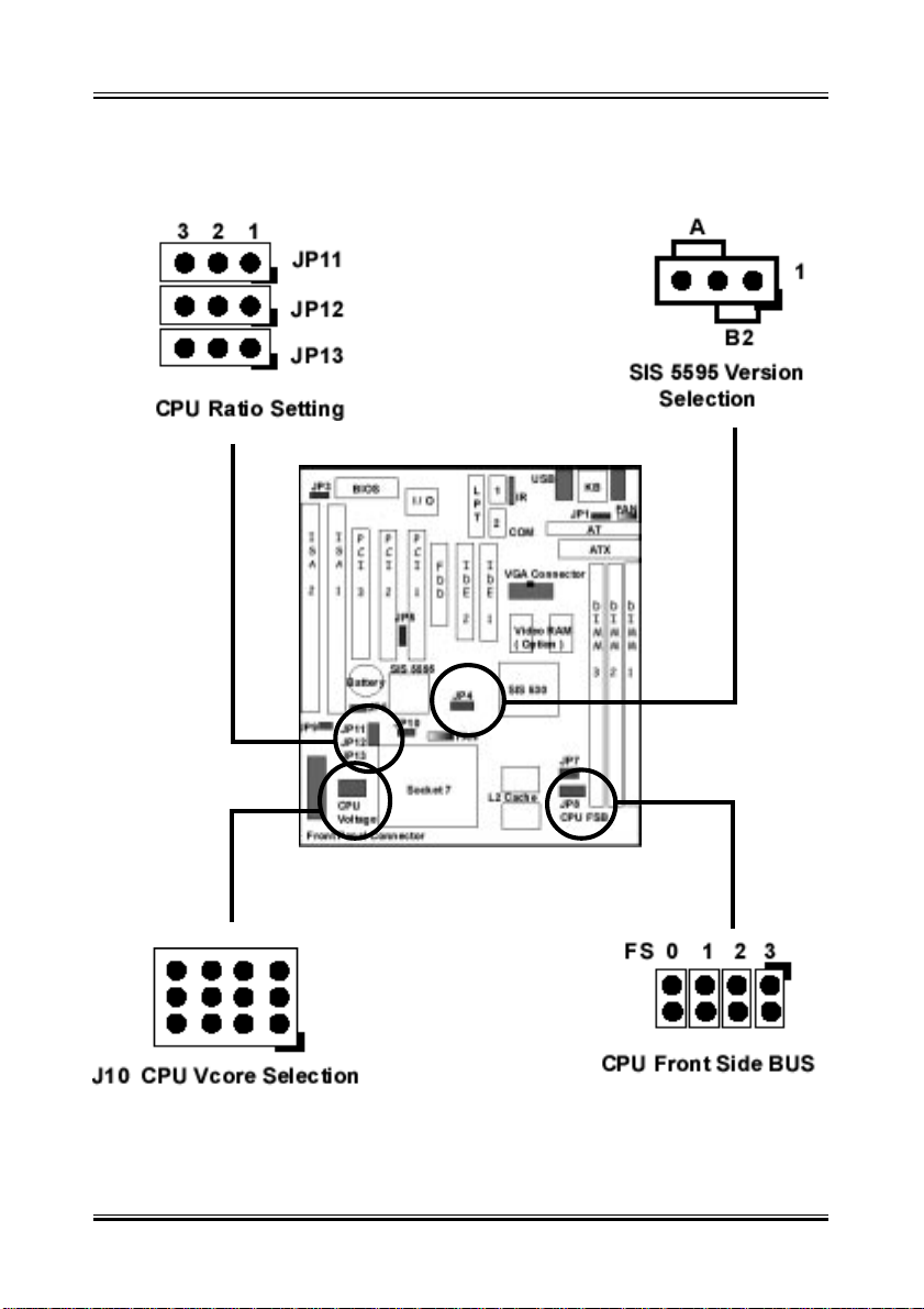
5-1 Jumpers Overview 8
5-2 CPU Jumper Setting 10
5-3 Install System Memory Modules 11
5-4 Install the Central Processing Unit (CPU) 12
5-5 External Conncetion 14
1. Power Cable 15
2. KB, Mouse and USB 17
3. Front Panel Connection 18
4. F AN, IR_DA, SB_Link and VGA Connection 19
5-6 Power On Procedure 21
Appendix: BIOS Setup Tips...................................................... 22
Item Checklist
Please check that your package is complete. If you discover damaged or
missing items, please contact your retailer.
Motherboard x 1
40-pin IDE Connector Flat Cable x 1
34-pin Floppy Disk Drive Flat Cable x 1
User Manual x 1; CD x 1
VGA Connector Flat Cable x 1
USB Connector Cable with bracket x 1 (Option)
IrDA Module x 1 (Option)
Option : Components will be include upon customer ordering instructions
per Proforma Invoice & additional external procurement cost will be included.
1
Page 2

User’s Manual Re v. A
1. Specifications
Microprocessor
Support Intel P54C/P55C, AMD K5/K6/K6-2, Cyrix M1/M2 and other Pentium
compatible CPUs 66/75/83/95/100/1 12 MHz host bus clock, selectable by jumpers ZIF Socket 7
Cache and System Memory
512KB pipeline burst synchronous SRAM
Three 168 pin dual in line memory module (DIMM) sockets
Support up to 768 MB of synchronous DRAM (SDRAM)
Chipset
SiS 530/5595 PCI AGP/VGA chip set
Integrated AGP VGA for hardware 2D/3D video/graphics accelerators
Integrated PCI bus mastering controller
Multifunction PCI-to-ISA bridge
Universal Serial Bus (USB) and DMA controller
Two PCI IDE interfaces that support up to four IDE drives or devices
Power management logic
Real time clock
V ideo/Graphics subsystems
Integrated high performance & high quality AGP 2D/3D accelerator
Programmable 2MB, 4MB, and 8MB shared frame buffer
Optional 4MB local frame buffer (manufacturing option)
24 bit true color RAMDAC up to 230MHz pixel clock, supports 1024*768 8/16/
32 bpp @85Hz NI
DVD hardware accelerator
2
Page 3

User’s Manual Re v. A
I/O features
1 x FDD Port support up to 2.88MB
1 x Parallel Port (LPT) support ECP/EPP
2 x High Speed Serial (16C550 UART) Ports
2 x Universal Serial Bus (USB) Ports
1 x A T Keyboard Port
1 x PS/2 Mouse Port
1 x IrDA Port
1 x VGA Port
Expansion slots
2X16 bit ISA slots
3X32 bit PCI slots
Other features
Award BIOS
Plug and Play compatible
Advanced Power Management (APM) 1.2 support
Advanced Configuration and Power Interface (ACPI) 1.0 support
Form factor
Baby A T ,220mmx230mm
3
Page 4

User’s Manual Re v. A
2. Chipset on this Mother Board
The Motherbaoard use the Chipset of SiS530 & SIS5595 where SIS 530 is
fuinction for Host, PCI, 3D A.G.P . V ideo/Graphics & Memory Controller and
the SiS5595 is function for PCI SYSTEM I/O.
The SiS530/5595 chipset, provides a high performance/cost index Desktop/
Mobile solution for the Intel Pentium P54C/P55C, AMD K5/K6/K6-II, Cyrix
M1/M2 and other compatible Pentium CPU with 3D A.G.P. VGA system.
The Host, PCI, 3D A.G.P. Video/Graphics & Memory Controller, SiS530
integrates the Host-to-PCI bridge, the PCI interface, the L2 cache controller,
the DRAM controller, the high performance hardware 2D/3D VGA controller ,
and the PCI IDE controller.
The Host interface supports Synchronous/Asynchronous Host/DRAM clocking configuration to eminently improve the system performance and DRAM
compatibility issues.
The L2 cache controller can support up to 1GB P.B. SRAM ( Default is
512KB ), and the DRAM controller can support SDRAM memory up to 768
MBytes.
The built-in fast PCI IDE controller supports the A T A PIO/DMA, and the Ultra
DMA33/66 function that support the data transfer rate up to 66 MB/s. It
provides the separate data path for two IDE channels that can eminently
improve the performance under the multi-tasking environment.
The A.G.P. internal interface is supported for integrated H/W 3D VGA controller. The integrated VGA controller is a high performance and targeted at
3D graphics application. In addition, the integrated 3D Video/Graphics controller adopts the 64bits 100MHz host bus interface high technology to improve the performance eminently . T o cost-effective the PC system, the share
system memory architecture will be adopted and it can flexibly using the
2MB, 4MB and 8MB frame buffer size from programming the system BIOS.
T o enhance the system performance, SiS530 also supports the local frame
buffer solution and memory sizes can support up to 8MB with SDRAM.
As for DVD solution, the integrated 3D VGA controller also support DVD H/
W accelerator to improve the DVD playback performance.
4
Page 5

User’s Manual Re v. A
The SiS5595 PCI system I/O integrates the PCI-to-ISA bridge with the DDMA,
PC/PCI DMA and Serial IRQ capability , the ACPI/Legacy PMU, the Data Acquisition Interface, the Universal Serial Bus host/hub interface, and the ISA bus
interface which contains the ISA bus controller, the DMA controllers, the interrupt controllers, the Timers and the Real Time Clock (RTC). It also integrates
the Keyboard Controller and PS/2 mouse interface that can support keyboard
power on function for users to power on system by entering the hot key or
password from keyboard.
The built-in USB controller, which is fully compliant to OHCI (Open Host Controller Interface), provides two USB ports capable of running full/low speed USB
devices.
The Data Acquisition Interface offers the ability of monitoring and reporting the
environmental condition of the PC. It could monitor 5 positive analog voltage
inputs, 2 Fan speed inputs, and one temperature input.
In addition, SiS5595 also supports ACPI function to meet Advanced Configuration and Power Interface (ACPI) 1.0 specification for Windows 98 environment,
it can support power-management timer, Power button, Real-time clock alarm
wake up, more sleeping state, ACPI LED for sleeping and working state
5
Page 6
User’s Manual Re v. A
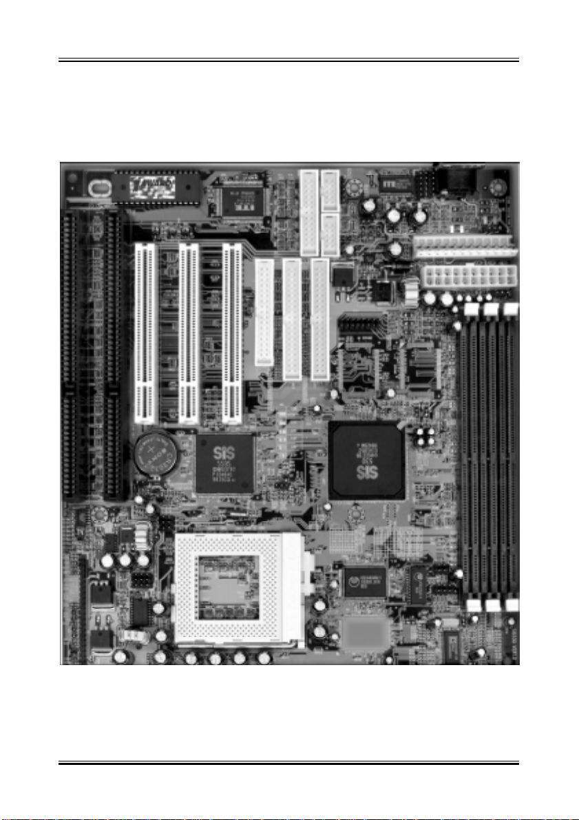
3. Parts Of The Mother Board
6
Page 7
User’s Manual Re v. A
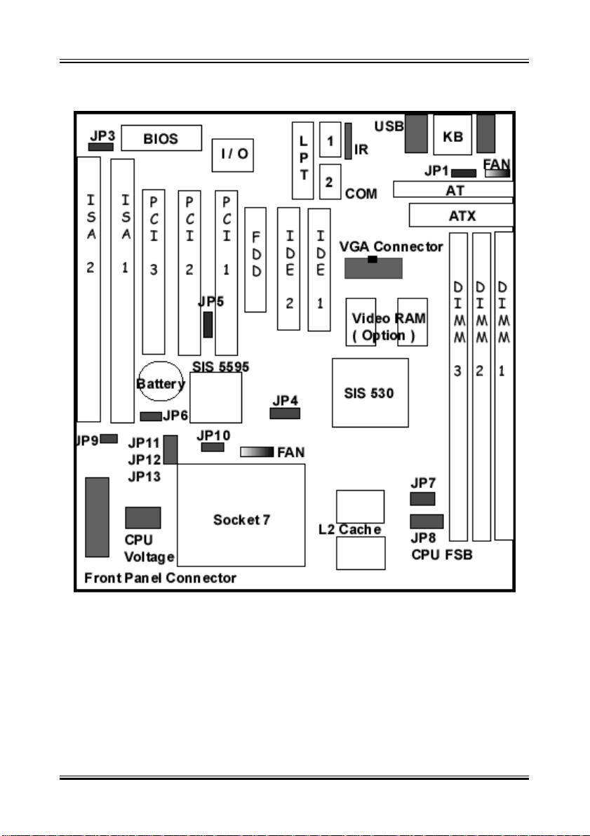
4. MotherBoard Layout Quick View
Special Connector description
JP1: AT & ATX Power Supply Selection
JP3: BIOS ROM Chip Voltage Selection
JP4: SiS5595 Version Selection
JP5: SB_Link Connector
JP6: CMOS Clear
JP7: L2 Cache Size Selection
JP8: CPU Front Side Bus Setting
JP9: CPU Voltage Auto detect Selection ( For Intel CPU Only )
JP10: L2 Cache Mode Selection
JP11~13 CPU Ratio Selection
7
Page 8
User’s Manual Re v. A
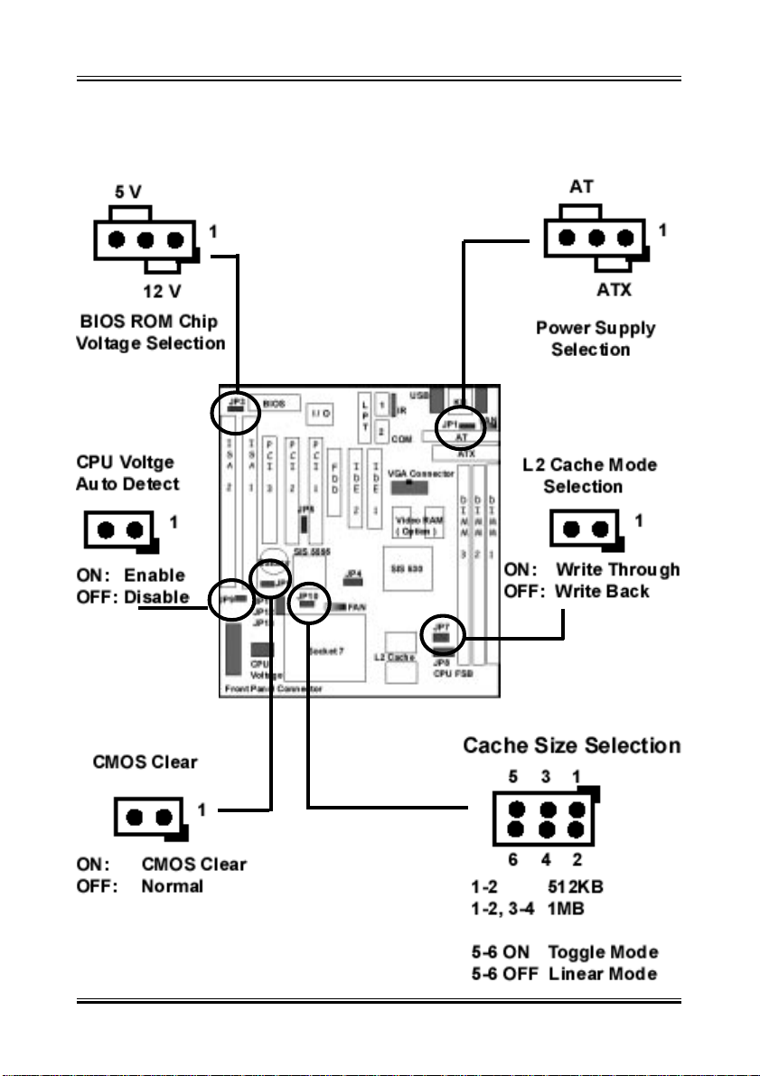
5-1 Jumper Overview
8
Page 9
User’s Manual Re v. A
9
Page 10
User’s Manual Re v. A
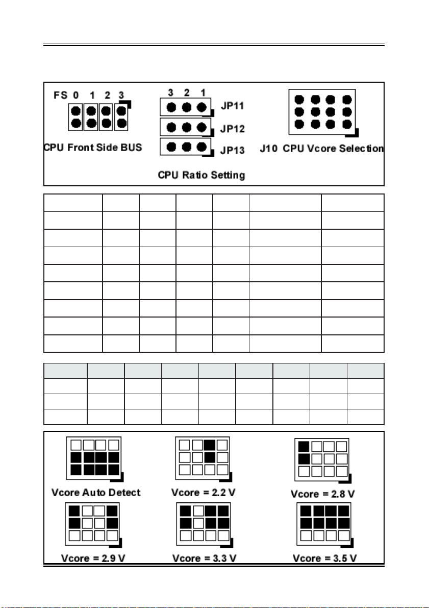
5-2 CPU Jumper Setting
kcolCUPC0SF1SF2SF3SFkcolCMARDSkcolCICP
ZHM66NONONOFFO6633
ZHM57FFONONOFFO5703
ZHM38NOFFONOFFO3833
ZHM59FFOFFONOFFO5913
ZHM001NONOFFOFFO00133
ZHM211FFONOFFOFFO21173
ZHM421NOFFOFFOFFO42113
ZHM331FFOFFOFFOFFO33133
x5.2x0.3x0.2x5.3x5.4x0.5x0.4x5.5
11PJ2-12-12-12-13-23-23-23-2
21PJ3-23-22-12-13-23-22-12-1
31PJ3-22-13-22-13-22-13-22-1
10
Page 11
User’s Manual Re v. A
5-3 Install System Memory Modules
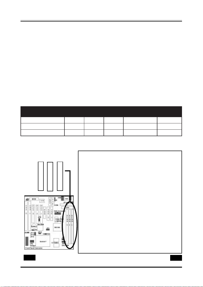
This motherboard support 3 slots for 168-pin 3.3V Non-buffered DIMM modules, providing support for up to 768 MB of main memory using DIMM modules
from 8MB to 256MB. For 66MHz host bus CPUs, please use 10ns or faster
DIMM modules. For 100MHz host bus CPUs, please use 8ns or faster DIMM
modules. The following is the example to install the system SDRAM memory
module combination: if you have two DIMM Modules, you has better install
them into DIMM Slot 1 & Slot 2 with the Max possible memory size up to
256MB ( 128 + 128 ) if the 128MB DIMM module is available.
ehtfosrebmuN
eludoMyromeM
1ts1BM652~8BM652
2ts1dn2BM652~8BM215
3ts1dn2dr3BM652~8BM867
23
1
1MMID 2MMID 3MMID eziSyromeM eziS.xaM
The DIMM types supported SDRAM (Synchronous DRAM). The following is the summary:
Single side:
1Mx64 (8MB), 2Mx64 (16MB), 4Mx64 (32MB),
8Mx64 (64MB), 16Mx64 (128MB)
Double side:
1Mx64x2 (16MB), 2Mx64x2 (32MB), 4Mx64x2
(64MB), 8Mx64x2 (128MB).
Total Memory Size:
There is no jumper setting required for the
memory size or type. It is automatically detected
by the system BIOS, and the total memory size
is to add them together.
Please Install the DIMM Module from DIMM Slot 1
11
Page 12

User’s Manual Re v. A
5-4 Install the Central Processing Unit (CPU)
Step 1: Set the CPU Freqency FSB Clock (JP8) [ Refer to Page 10 ]
1. The SDRAM Clock will depending on the DIMM Module the User used.
The PC-100 spec. SDRAM basicly can support 100MHZ or above Clock
2. The possible Front Side Bus setting are from 66 to 133 MHz.
3. If you want to overclock the CPU, please make sure the other
peripher als can work fine with one another. That mean you need to
well test the whole system with your own configuration, otherwise,
please set the default and safe setting with 66MHZ or 100MHZ front
side bus.
3. Please make sure you are using the correct DIMM module with the
related CPU type. For the 100MHZ or faster front side bus, you need to
use the PC100 type DIMM module.
Step 2: Set CPU Freqency Ratio ( JP11, JP12, JP13 ) [ Refer to Page 10 ]
1. Normally , The CPU itself will mention about the Frequency and the
Clock Ratio and also the Voltage of the Vcore, Please refer to the CPU
Type ans select the correct CPU Ratio
Step 3: Set the CPU Voltage, Vcore ( J10 ) [ Refer to Page 10 ]
1. There are the voltage range from 2.2V to 3.5V could be secectable.
Please refer to the CPU specification to set the correct CPU Vcore.
2. User also can set the Jumper ( J10 ) to CPU V oltage as Auto Detect
( Refer to page 10 ) form the AMD series CPU. For the Intel series
CPU, User need to set further jumper JP9 as OFF for the CPU Voltage
auto detect
12
Page 13
User’s Manual Re v. A
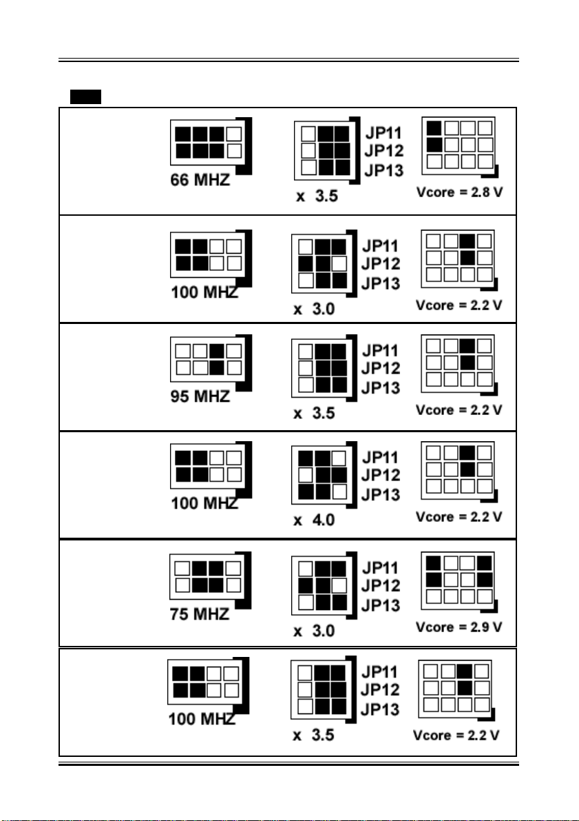
Example for the most current CPU Setting:
Intel MMX
233 MHZ
AMD K6-2
300 MHZ
AMD K6-2
333 MHZ
AMD K6-2
400 MHZ
Cyrix MII
300MHZ
AMD K6-2
350 MHZ
13
Page 14

User’s Manual Re v. A
5-5 External Conncetion
1.Unplug your power supply when adding or removing expansion cards or other
system components. Failure to do so may cause severe damage to both your
motherboard and expansion cards.
2.Ribbon cables should always be connected with the red stripe on the Pin 1
side of the connector. The Four Corners of the connectors are labeled on the
motherboard. Pin 1 is the side closest to the power connector on hard drives
and floppy drives. IDE ribbon cable must be less than 18in. (46cm), with the
second drive connector no more than 6in. (15cm) from the first connector.
3.The motherboard requires a power supply and a “power good” signal. Make
the A TX power supply can take at least 10mAmp load on the 5V Standby lead
(5VSB) to meet the standard A TX specification.
4. To prevent electrical spikes, make sure that the power supply is not connected to an outlet when making or removing connections. Power supplies
contain power remains, which can damage electrical components.
5. Expansion Card Installation Procedure
! Read the documentation for your expansion card and make any
necessary hardware or software settings for your expansion card, such as
jumpers.
! Remove your computer system’s cover and the bracket plate on the slot
you intend to use. Keep the bracket for possible future use.
! Carefully align the card’s connectors and press firmly .
! Secure the card on the slot with the screw you removed above.
! Replace the computer system’s cover .
! Set up the BIOS if necessary (such as IRQ xx Used By ISA: Yes in PNP
AND PCI SETUP)
14
Page 15
User’s Manual Re v. A
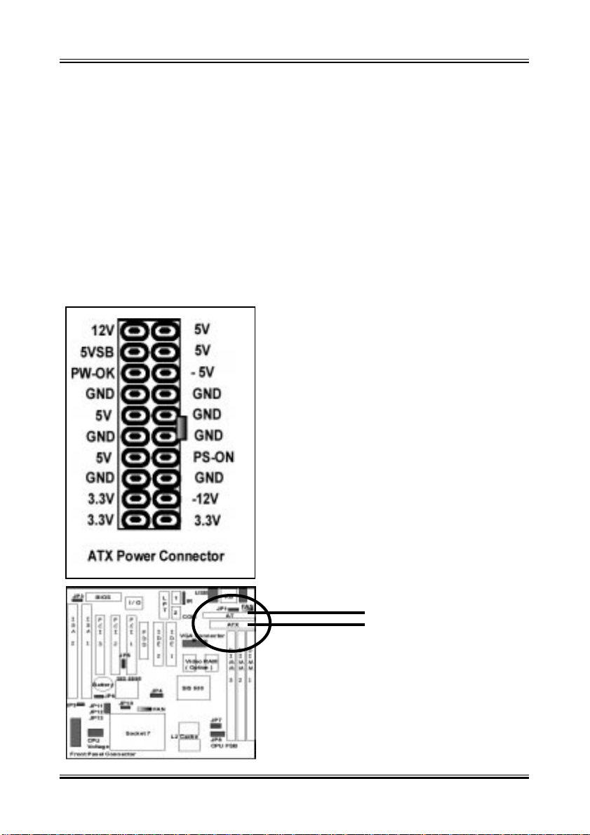
5-5-1 Power Cable
A TX Power Supply Connector (A TXPWR, 20-pins)
Plug the connector from the power directly into the 20-pin male A TX PW connector on the motherboard as shown in the following figure. The plug from the
power supply will only insert in one orientation because of the different hole
sizes. Find the proper orientation and push down firmly making sure that the
pins are aligned and the power supply is off before connecting or disconnecting
the power cable.
Make sure that your A TX power supply
can supply at least 10 mAmp on the 5volt standby lead (5VSTB). Y ou may experience difficulty in powering on your
system if your power supply cannot support the load. For Wake on LAN support, your A TX power supply must supply at least 1 Amp.
Y ou should plug in/out the Power Cable
to/from the Mother Board more carefully ,
all the Pins should be conect at the
same time.
15
AT Power Supply
ATX Power Supply
Page 16
User’s Manual Re v. A
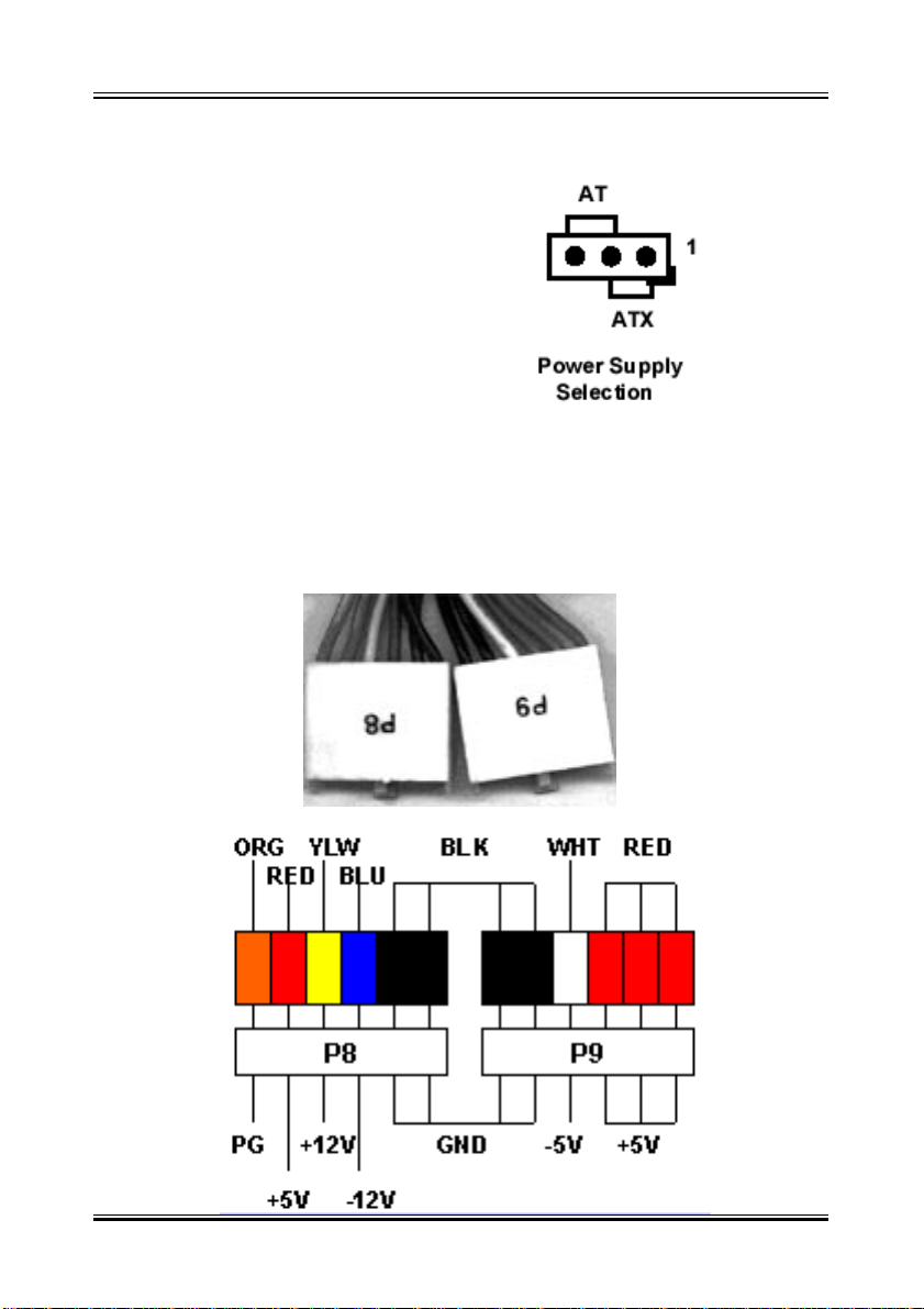
A T Power Supply Connector (A TPOWER, 12-pins)
Refer to Page to Page 8
Set the JP1 as 2-3 for AT Power Supplt
This connector connects to a standard AT power supply. To connect the
leads from the power supply , ensure first that the power supply is not plugged.
Most power supplies provide two plugs (P8 and P9), each containing six
wires, two of which are black. Orient the connectors so that the black wires
are together. Please refer to the following:
16
Page 17
User’s Manual Re v. A
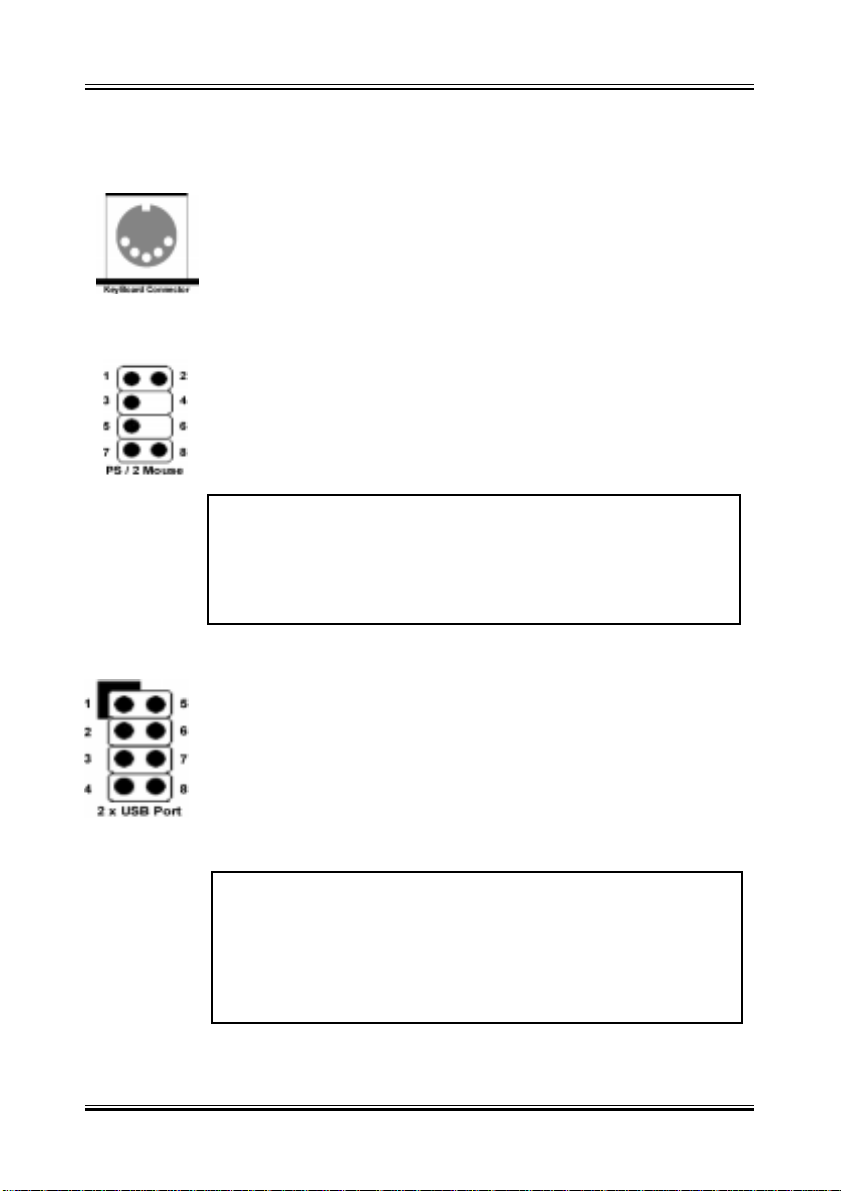
5-5-2 KB, Mouse, USB
The onboard keyboard connector
is a five-pin A T-compatible connector. The view angle of drawing shown here is from back panel of the housing. If you want
to use the PS/2 Keyboard, you need to add one adapter that
converts the signal from A T to PS/2 specification.
PS/2 Mouse Connector
The onboard PS/2 mouse connector is a 6-pin Mini-Din connector marked PS2.The view angle of drawing shown here is
from back panel of the housing.
Pin Description Pin Description
1 Mouse Data 2 N.C.
3 Ground 4 +5VDC
5 Mouse CLK 6 N. C
USB Connector X 2
Y ou can attach USB devices to the USB connector . The Mother
board contains two USB connectors. USB is a new serial bus
design that is capable of cascading low-/medium-speed peripherals (less than 12Mbps) such as keyboard, mouse, joystick,
scanner, printer and modem/ISDN.
Pin Description Pin Description
1 +5 VDC 5 +5VDC
2DATA - 6DATA3DATA + 7DATA+
4 Ground 8 Ground
17
Page 18
User’s Manual Re v. A
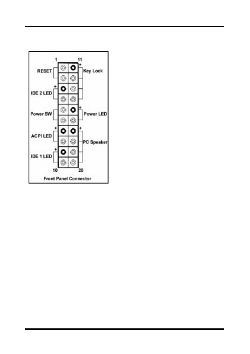
5-5-3 Front Panel Connection
1). IDE Activity LED ( Pin 9,10)
This connector connects to the IDE (hard
disk) activity indicator light on the system
abinet.
2). System Power LED ( Pin 15,16 )
This 3-pin connector lights the system
power LED when the motherboard has
power.
3). ACPI LED (Pin 7,8)
ACPI LED can use to control the blinking
of a LED at the freqency of 1 HZ to indicate the system is at power saving mode.
4). A TX Power Switch ( Pin 5,6 )
The system power is controlled by a push-switch, connected to this lead.
Pushing the button once will turn on the power and pushing again will turn off
the power . The system power LED shows that status of the system’s power .
If the power to the A TX power supply is interrupted while the motherboard is
on, standby power will remember that the motherboard should be on and
boot the computer when power is reapplied to the A TX power supply .
5). Reset Switch ( Pin 1,2 )
This 2-pin connector connects to the case-mounted reset switch for
rebooting your computer without having to turn off your power switch. This
is a preferred method of rebooting in order to prolong the life of the system
power supply .
6). IDE 2 Activity LED ( Pin 3,4 )
Further indicator for the IDE 2 Device Activity LED
18
Page 19
User’s Manual Re v. A
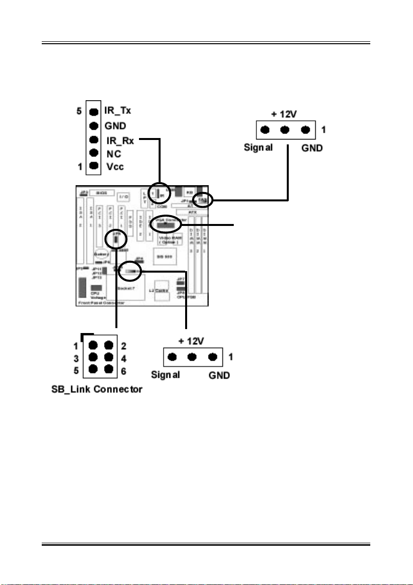
5-5-4 FAN, IR, SB_Link, VGA Connector
IR
SYSTEM
FAN
A. VGA Connector:
Directly connect this Connector to
a Blacket with D-Sub 15Pin VGA
Connector On the Back Panel. For
the Monitor Cable Plug In.
CPU FAN
B. CPU & System Cooling FAN Connector:
This connectors support a CPU cooling fan of 500 mA (6WA TT , +12V) or
less. Orient the fan so that the heat sink fins allow airflow to go across
the onboard heat sink(s). Depending on the fan manufacturer, the wiring
and plug may be different. The red wire should be positive (+12V), while
the black should be ground. Connect the fan plug to the board taking into
consideration the polarity of the connector.
19
Page 20
User’s Manual Re v. A
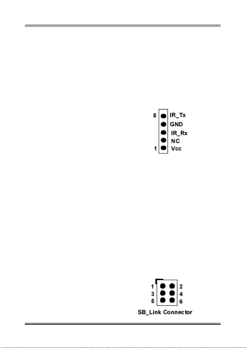
C. IrDA Compliant Infrared Module Connector
This connector support the optional wireless transmitting and receiving
infrared module. This module mounts to a small opening on system cases
that support this feature. Y ou must also configure UART 2. Use Infrared
in Chipset Features Setup to select whether UART 2 is directed for use
with COM2 or IrDA. When IrDA is selected in BIOS, COM2 will be disabled. Use the five pins as shown and connect a ribbon cable from the
module to the motherboard to the pin definitions.
Pin 1 Vcc
Pin 2 NC
Pin 3 IR_RX
Pin 4 GND
Pin 5 IR_ TX
D. SB-Link
originated from Creative to propose a standard which can be a bridge
between the mainboard and PCI sound card to deliver Sound Blaster 16
compatibility under DOS real-mode environment. Sound Blaster 16 was
almost the standard of the ISA Bus sound cards, a lot of games were
Programmed for Sound Blaster especially under DOS environment. If the
users are still interested in playing these game titles, they might have
compatibility problems with the new up graded PCI Bus sound card. This
header adopts Intels PC/PCI technology to deliver Sound Blaster 16 compatibility to PCI Bus sound card, enabling users to play real-mode DOS
games. Connect the cable provided by PCI sound card to this connector.
Pin Significance of signal
1 GNT#
2 Ground
3 KEY
4 REQ#
5 Ground
6 SERIRQ
20
Page 21

User’s Manual Re v. A
5-6 Power On Procedure
1.After all connections are made, close the system case cover.
2.Be sure that all switches are off (in some systems, marked with 0)
3.Make sure your power supply voltage is correctly set to 1 10V or 230V .
4.Connect the power supply cord into the power supply located on the back of
your system case according to your system user’s manual.
5.Connect the power cord into a power outlet that is equipped with a surge
protector.
6.Y ou may then turn on your devices in the following order:
Y our monitor
External SCSI devices (starting with the last device on the chain)
Y our system power . For A TX power supplies, you need to switch on the power
supply as well as press the A TX power switch on the front of the case.
7.The power LED on the front panel of the system case will light. For A TX power
supplies, the system LED will light when the A TX power switch is pressed. The
monitor LED may light up after the system power up. if it complies with “green”
standards or if it has a power standby feature. The system will then run poweron tests. While the tests are running, additional messages will appear on the
screen. If you do not see anything within 30 seconds from the time you turn on
the power, the system may have failed a power-on test. Recheck your jumper
settings and connections or call your retailer for assistance.
8.During power-on, hold down <Delete> to enter BIOS setup menu if you want
to run the BIOS Setup Utility .
Powering Off your computer: You must first exit or shut down your operating
system before switching off the power switch. For A TX power supplies, you can
press the A TX power switch after exiting or shutting down your operating system. If you use Windows 95/98, click the Start button, click Shut Down, and
then click Shut down the computer. The system will give three quick beeps
after about 30 seconds and then power off after Windows shuts down.
The message “Y ou can now safely turn of f your computer” will not appear when
shutting down with ATX power supplies.
21
 Loading...