

Page 1
Manual Rev. A
CONTENTS
1. Specification ................................................................... 2
2. Parts Of The Mother Board .................................................. 4
3. MotherBoard Layout Quick View ............................................ 5
4. Installation .................................................................... 6
4-1 Jumper Overview 6
4-2 CPU Setting 8
4-3 Install System Memory Modules 9
4-4 External Conncetion 10
4-5 A TX Power Supply Connector 1 1
4-6 KeyBoard , Mouse, USB, COM / LPT / Sound 12
4-7 Front Panel Connection 14
4-8 FAN, IR, WOL, CD IN Connector 15
4-9 Power On Procedure 17
Appendix: BIOS Setup Tips...................................................... 18
Item Checklist
Please check that your package is complete. If you discover damaged or
missing items, please contact your retailer.
Motherboard x 1
40-pin IDE Connector Flat Cable x 1
34-pin Floppy Disk Drive Flat Cable x 1
User Manual x 1; CD x 1
Option : Components will be include upon customer ordering instructions
per Proforma Invoice & additional external procurement cost will be
included.
1
Page 2

Manual Rev. A
1. Specification
Microprocessor
č Support for a single Intel PPGA Mendocino processor
č Supports 66MHz host bus speed ( 100MHZ Clock will be supported in
the feature when CPU is available ), selectable by BIOS
č PPGA socket 370
Cache and System Memory
č 128KB cache, built-in Mendocino processor
č 2 x 168-pin dual inline memory module (DIMM) sockets
č Supports up to 256 MB of synchronous DRAM (SDRAM)
Chipset (Intel 82440ZX AGPset and PCI/IDE Interface)
č Intel 82443ZX PCI/AGP controller (P AC)
Integrated PCI bus mastering controller
Integrated Accelerated Graphics Port (AGP) interface
č Intel 82371EB PCI/ISA/IDE Xcelerator (PIIX4E)
Multifunction PCI-to-ISA bridge
Universal Serial Bus (USB) and DMA controllers
Two fast IDE interfaces that support up to four IDE drives or devices
Power management logic
Real-time clock
Audio Subsystmes
č ESS solo1 PCI 3D single chip audio controller
č Line-out, Mic-in , Line-in, MIDI/Game Port
I/O Features
č Winbond 83977 super I/O controller
č 1xFDD Port support up to 2.88MB
č 1xParallel Port (LPT) support ECP/EPP
č 2xHigh Speed Serial (16C550 UART) Ports
2
Page 3

Manual Rev. A
č 2 x IDE Ports support ultra DMA/33
č 2xUniversal Serial Bus (USB) Ports
č 1xPS/2 Keyboard Port
č 1xPS/2 Mouse Port
č 2xIrDA Front and Rear Port
Expansion Slots
č 1 x 16-bit ISA Slot
č 3 x 32-bit PCI Slots
č 1 x 32-bit AGP Slot
Other Features
č Award BIOS (2 Mb flash memory)
č Plug and Play compatible
č Jumperless configuration
č Advanced Power Management (APM) 1.2 support
č Advanced Configuration and Power Interface (ACPI) 1.0 support
č Hardware monitoring and alert (Optional)
č Modem ring wake up and power up. Wake on LAN
č Keyboard power on and PS/2 mouse power on
Form Factor
Micro ATX, 244mmX200mm
3
Page 4
Manual Rev. A
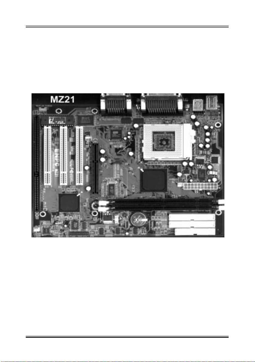
2. Parts Of The Mother Board
4
Page 5
Manual Rev. A
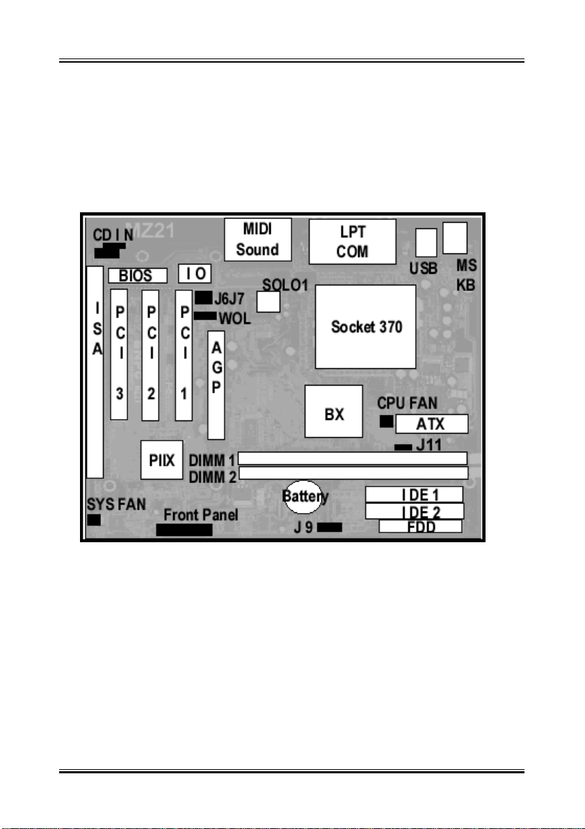
3. MotherBoard Layout Quick View
Jumper:
1. J11: FSB 66 MHZ / 100 MHZ Switching
2. J 9: CMOS Clear ( Set the BIOS Data to Factory default )
3. J 7/J 6: On Board Sound Chip Enable / Disable
5
Page 6
Manual Rev. A
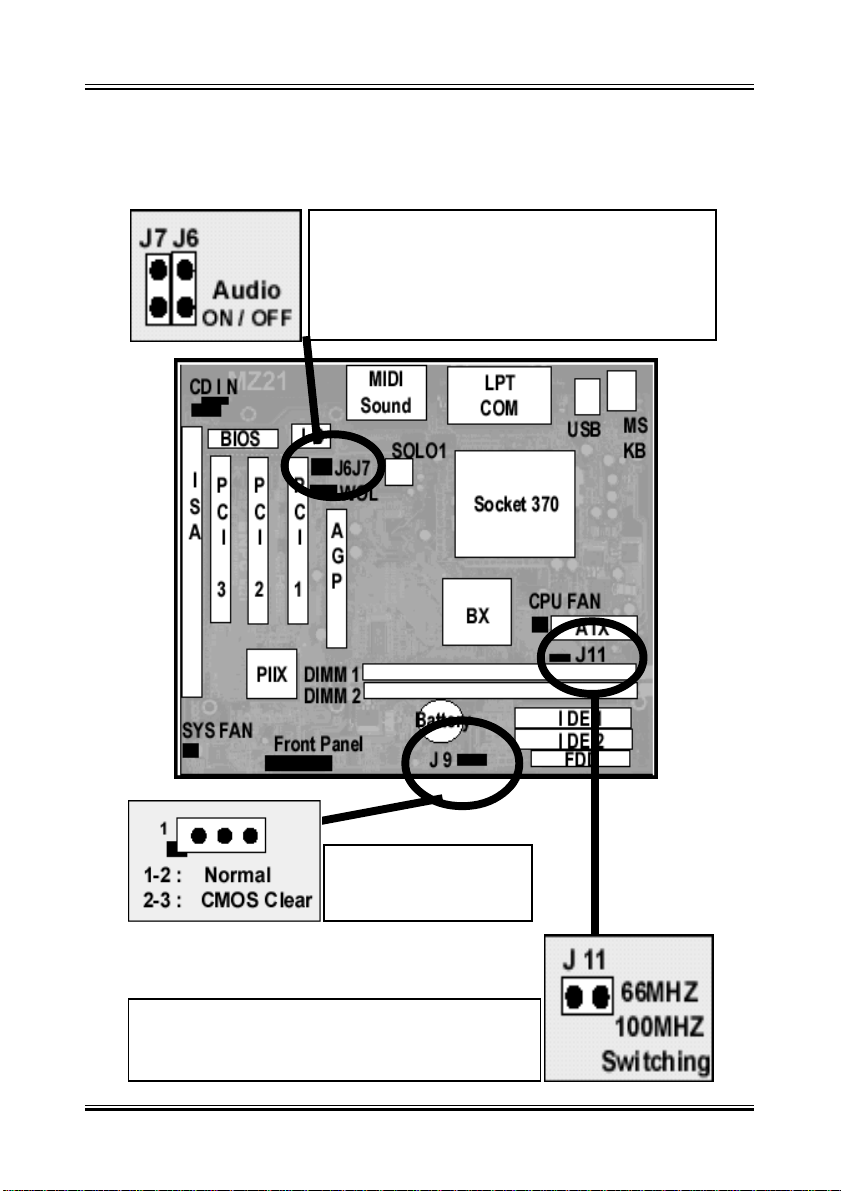
4-1 Jumper Overview
ON: Enable On Board Audio
OFF: Disable On Board Audio
1-2 Normal
2-3 Clear CMOS
ON: For 66 MHZ FSB
OFF: For 100 MHZ FSB
6
Page 7

Manual Rev. A
CMOS Clearing
CMOS Clear, which is a safety hook if you forget the password. Sometime , if
user change the CPU and making the BIOS difficult to recognize the CPU
type, Clear CMOS will help BIOS to re-config the system successfully .
Follow the steps:
After you have turned off your computer, clear the CMOS memory by momentarily shorting pins 2-3, for a few seconds. Then restore it to the initial
1-2 jumper setting in order to recover and retain the default settings. Reset
your computer now.
J11 ( 66MHZ / 100 MHZ Switching )
If overclock the CPU from 66MHZ to 100 MHZ on the jumperless design mother
board the following symptom will happen:
The AGP card will run 100 MHZ with the AGP Clock, inside the AGP
Chip will run up to 200MHZ ( For 2x AGP Card ) instead of the
66MHZ x 2 = 133MHZ
That¡¦s because the CPU origonal is 66MHZ FSB design by Intel, When you
overclock the CPU to 100MHZ, the Chipset didn¡¦t know you force the Clock
to 100MHZ by BIOS, it will let the 100MHZ as AGP Clock. If you use the
66MHZ for that CPU, the AGP Card clock will be 66MHZ; If you use the
origonal 100 MHZ FSB CPU , the Chipset recognized the CPU is 100MHZ
FSB design, it will reduce the 100MHZ / 1.5 = 66MHZ, then the AGP will run
66MHZ( Inside AGP will be 66MHZ x 2 = 133 MHZ ).
If use the 100MHZ FSB,
Regardless use the 66MHZ or 100MHZ type CPU
Set the J11 to OFF.
7
Page 8
Manual Rev. A
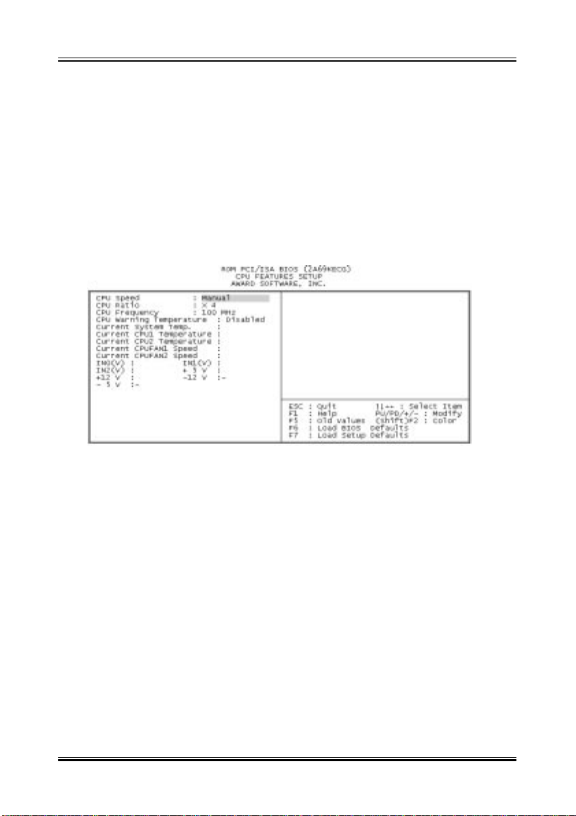
4-2 CPU Setting
Selecting the CPU Frequency
The CPU frequency selection is set with the followings:
BIOS Setup
(The possible setting is 66, 75, 83 , 100, 103, 1 12, 124, 133 MHZ)
BIOS Setup
(The possible setting is 3x, 3.5x, 4x, 4.5x, 5x, 5.5x, 6x)
èè
è CPU Speed Setting
èè
èè
è CPU Speed Setting
èè
è è
è CPU Freuency
è è
è è
è CPU Ratio
è è
Notes:
1. Most current Intel Pentium II, Pentium III or Celeron CPU will fix the CPU
Clock Ratio, User just need to deside the CPU Front Side Bus for the CPU.
The Mother Board provide the Clock from 66MHZ to 112 MHZ for user to
setup.
2. User can define the CPU Clock Ratio in the BIOS setup utility for the
CPU which did not fix the Clock Ratio. If the CPU fix the Ratio, the CPU Clock
ratio will be no changed.
3. If user fail to power up the system ( No Display ), please Clear the CMOS
then boot up again or Press [Insert] key to power up the system. If still fail,please
check the Memory is contact well or not and also well adjest the CPU Front
Side Bus for the related CPU.
8
Page 9
Manual Rev. A
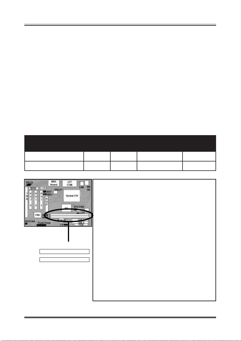
4-3 Install System Memory Modules
This motherboard support 2 slots for 168-pin 3.3V Non-buffered DIMM modules, providing support for up to 256 MB of main memory using DIMM modules from 8MB to 128MB. For 66MHz host bus CPUs, please use 10ns or
faster DIMM modules. For 100MHz host bus CPUs, please use 8ns or faster
DIMM modules. The following is the example to install the system SDRAM
memory module combination: if you have two DIMM Modules, you has better
install them into DIMM Slot 1 & Slot 2 with the Max possible memory size up
to 256MB ( 128 + 128 ) if the 128MB DIMM module is available.
ehtfosrebmuN
eludoMyromeM
1ts1BM821~8BM821
2ts1dn2BM821~8BM652
1
2
1MMID 2MMID eziSyromeM eziS.xaM
The DIMM types supported SDRAM (Synchronous DRAM). The following is the summary:
Single side:
1Mx64 (8MB), 2Mx64 (16MB), 4Mx64 (32MB),
8Mx64 (64MB), 16Mx64 (128MB)
Double side:
1Mx64x2 (16MB), 2Mx64x2 (32MB), 4Mx64x2
(64MB), 8Mx64x2 (128MB).
Total Memory Size:
There is no jumper setting required for the
memory size or type. It is automatically detected
by the system BIOS, and the total memory size
is to add them together.
9
Page 10

Manual Rev. A
4-4 External Conncetion
1.Unplug your power supply when adding or removing expansion cards or
other system components. Failure to do so may cause severe damage to
both your motherboard and expansion cards.
2.Ribbon cables should always be connected with the red stripe on the Pin 1
side of the connector. The Four Corners of the connectors are labeled on the
motherboard. Pin 1 is the side closest to the power connector on hard drives
and floppy drives. IDE ribbon cable must be less than 18in. (46cm), with the
second drive connector no more than 6in. (15cm) from the first connector.
3.The motherboard requires a power supply and a power good signal. Make
the ATX power supply can take at least 10mAmp load on the 5V Standby
lead (5VSB) to meet the standard A TX specification.
4. To prevent electrical spikes, make sure that the power supply is not connected to an outlet when making or removing connections. Power supplies
contain power remains, which can damage electrical components.
5. Expansion Card Installation Procedure
! Read the documentation for your expansion card and make any
necessary hardware or software settings for your expansion card, such as
jumpers.
! Remove your computer system’s cover and the bracket plate on the slot
you intend to use. Keep the bracket for possible future use.
! Carefully align the card’s connectors and press firmly.
! Secure the card on the slot with the screw you removed above.
! Replace the computer system’s cover.
! Set up the BIOS if necessary (such as IRQ xx Used By ISA: Yes in PNP
AND PCI SETUP)
10
Page 11
Manual Rev. A
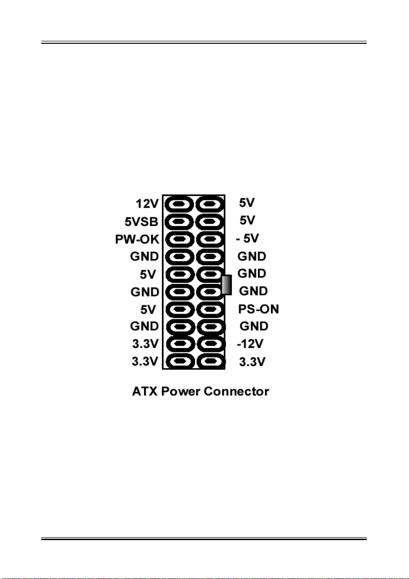
4-5 ATX Power Supply Connector
Plug the connector from the power directly into the 20-pin male A TX PW connector on the motherboard as shown in the following figure. The plug from the
power supply will only insert in one orientation because of the different hole
sizes. Find the proper orientation and push down firmly making sure that the
pins are aligned and the power supply is off before connecting or disconnecting the power cable.
Make sure that your A TX power supply can supply at least 10 mAmp on the
5-volt standby lead (5VSTB). Y ou may experience difficulty in powering on
your system if your power supply cannot support the load. For Wake on
LAN support, your A TX power supply must supply at least 1 Amp.
You should plug in/out the Power Cable to/from the Mother Board more
carefully , all the Pins should be conect at the same time.
11
Page 12
Manual Rev. A
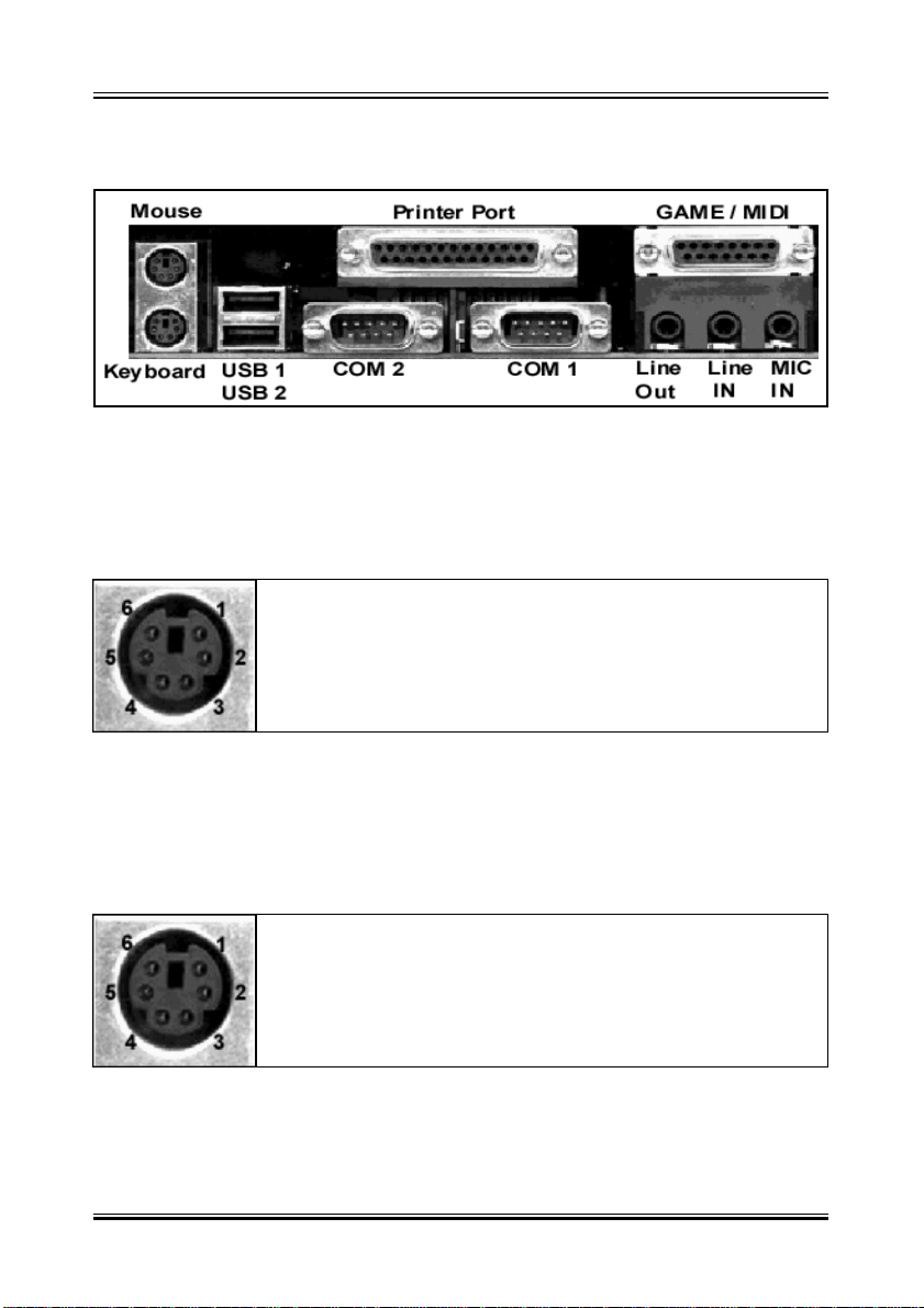
4-6 KB, Mouse, USB,COM and LPT
PS/2 Keyboard Connector
The onboard PS/2 keyboard connector.The view angle of drawing shown
here is from back panel of the housing.
Pin Description Pin Description
1 Keyboard Clock 2 GND
3 Keyboard Data 4 N.C.
5 +5VDC 6 N.C.
PS/2 Mouse Connector
The onboard PS/2 mouse connector.The vie w angle of dr awing sho wn
here is from back panel of the housing.
Pin Description Pin Description
1 Mouse Clock 2 GND
3 Mouse Data 4 N.C
5 +5VDC 6 N.C
12
Page 13

Manual Rev. A
USB (Universal Serial Bus Connector)
You can attach USB devices to the USB connector. The Mother board
contains two USB connectors, which are marked as USB . USB is a new
serial bus design that is capable of cascading low-/medium-speed peripherals (less than 12Mbps) such as keyboard, mouse , joystick, scanner,
printer and modem/ISDN. With USB, complex cable connections at the
back panel of your PC can be eliminated.
Pin Description Pin Description
1 +5 VDC 5 +5VDC
2 DATA - 6 DATA3 DATA + 7 DATA+
4 Ground 8 Ground
Serial Devices (COM1/COM2)
The onboard serial connectors are 9-pin D-type connector on the back
Panel of mainboard. The serial port 1 connector is marked as COM1 and
the serial port 2 connector is marked as COM2.
Printer Port ( LPT )
The onboard printer connector is a 25-pin D-type connector marked
PRINTER. The view angle of drawing shown here is from back panel of the
housing.
Line In
For the External Audio signal Input
Mic In
Connect to Microphone
Line Out ( Speaker Out )
Connect to Speaker
MIDI / GAME Port
Connect to MIDI device or Game Pad or joystic
13
Page 14
Manual Rev. A
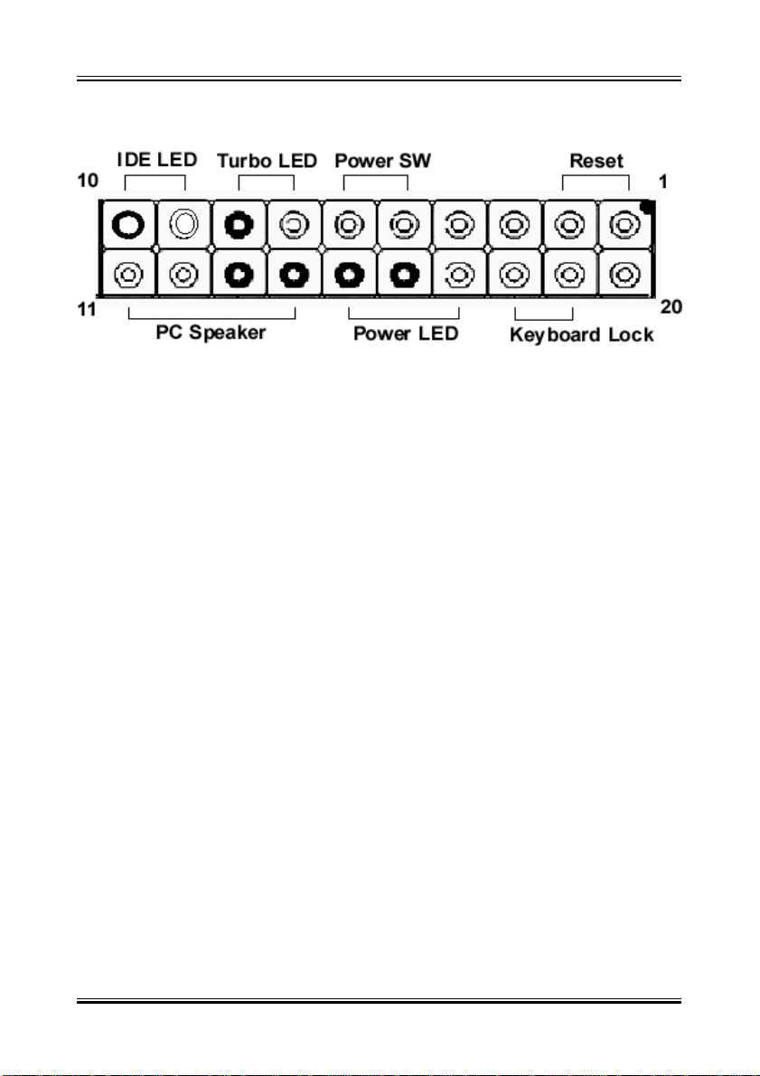
4-7 Front Panel Connection
1). IDE Activity LED ( Pin 9,10)
This connector connects to the IDE (hard disk) activity indicator light
2). System Power LED ( Pin 15,16,17)
This 3-pin connector lights the system power LED when the motherboard
has power.
3). T urbo LED (Pin 7,8)
If the cabinet provide the turbo LED cable, connect the cable to this two pin
connector to turn on the LED on the front panel.
4). A TX Power Switch ( Pin 5,6 )
The system power is controlled by a push-switch, connected to this lead.
Pushing the button once will turn on the power and pushing again will turn
off the power .
5). Reset Switch ( Pin 1,2 )
This 2-pin connector connects to the case-mounted reset switch for
rebooting your computer without having to turn off your power switch. This
is a preferred method of rebooting in order to prolong the life of the system
power supply .
6). Keyboard Lock Switch Lead ( Pin 18,19 )
This 3-pin connector connects to the case-mounted keyboard lock switch
for locking the keyboard.
7). Speaker Connector ( Pin 11,12,13,14 )
This 4-pin connector connects to the case-mounted speaker.
14
Page 15
Manual Rev. A
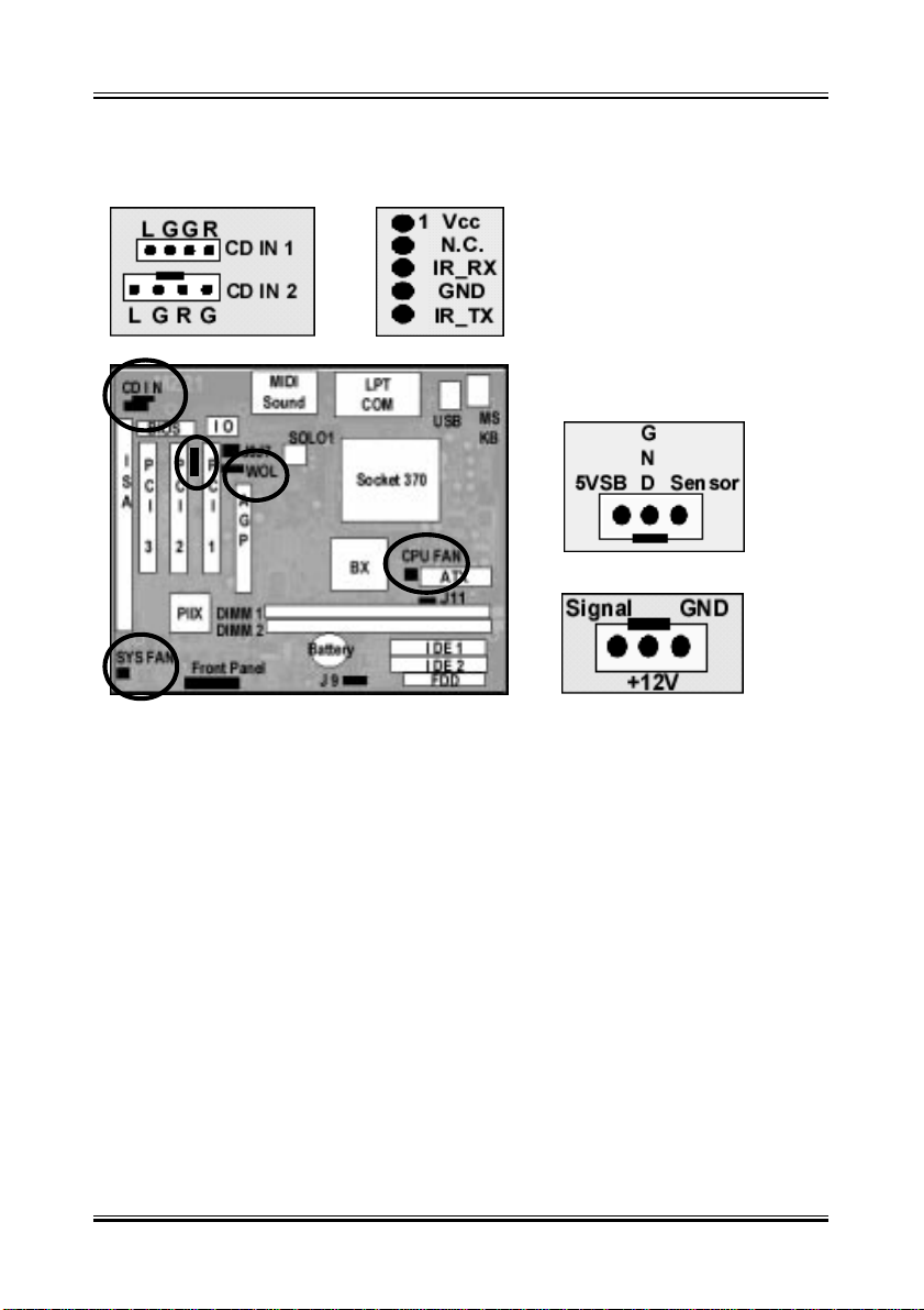
4-8 FAN, IR, WOL, CD IN Connector
A. CPU & System Cooling FAN Connector:
This connectors support a CPU cooling fan of 500 mA (6WATT, +12V)
or less. Orient the fan so that the heat sink fins allow airflow to go across
the onboard heat sink(s). Depending on the fan manufacturer, the wiring and plug may be different. The red wire should be positive (+12V),
while the black should be ground. Connect the fan plug to the board
taking into consideration the polarity of the connector.
15
Page 16

Manual Rev. A
B. IrDA Compliant Infrared Module Connector
This connector support the optional wireless transmitting and receiving
infrared module. This module mounts to a small opening on system
cases that support this feature. You must also configure U ART 2. Use
Infrared in Chipset Features Setup to select whether UART 2 is directed
for use with COM2 or IrD A. When IrDA is selected in BIOS, COM2 will
be disabled. Use the five pins as sho wn and connect a ribbon cable
from the module to the motherboard to the pin definitions.
Pin 1 Vcc
Pin 2 NC
Pin 3 IR_RX
Pin 4 GND
Pin 5 IR_TX
C. Wake-On-LAN (WOL)
Attach the 3-pin connector from the LAN card which supports the Wak e-OnLAN (WOL) function to the W OL connector on the motherboard.
This W OL function lets users wak e up the connected computer through
the LAN card. Please install according to the f ollo wing pin assignment b y
the Page 15.
D. CD IN Connector
Provied 2 CD Audio Input Connectors that depending on the Cab le
user have , which connect from CDROM to this Connector
16
Page 17

Manual Rev. A
4-9 Power On Procedure
1.After all connections are made, close the system case cover.
2.Be sure that all switches are off (in some systems, marked with 0)
3.Make sure your pow er supply voltage is correctly set to 110V or 230V.
4.Connect the power supply cord into the power supply on the bac k
5.Connect the power cord into a power outlet
6.You may then turn on your de vices in the following order:
Your monitor
External SCSI devices (starting with the last device on the chain)
Your system power. (press the ATX power switch on the front of the case.)
7.The power LED on the front panel of the system case will light. For ATX
power supplies, the system LED will light when the ATX power s witch is
pressed.The monitor LED may light up after the system power up. if it
complies with green standards or if it has a power standby feature. The
system will then run power-on tests. While the tests are running, additional
messages will appear on the screen. If y ou do not see anything within 30
seconds from the time you turn on the power , the system may have failed a
power-on test. Recheck your jumper settings and connections or call your
retailer for assistance.
8.During power-on, hold down <Delete> to enter BIOS setup menu if y ou
want to run the BIOS Setup Utility.
Po w ering Off y our computer: You must first exit or shut do wn y our operating
system before switching off the power switch. For ATX power supplies, you
can press the ATX power switch after e xiting or shutting do wn y our oper ating system. If you use Windo ws 95/98, clic k the Start button, click Shut
Down, and then click Shut down the computer. The system will give three
quick beeps after about 30 seconds and then power off after Windo ws shuts
down. The message You can now safely turn off your computer will not
appear when shutting down with ATX power supplies.
17
Page 18
Manual Rev. A
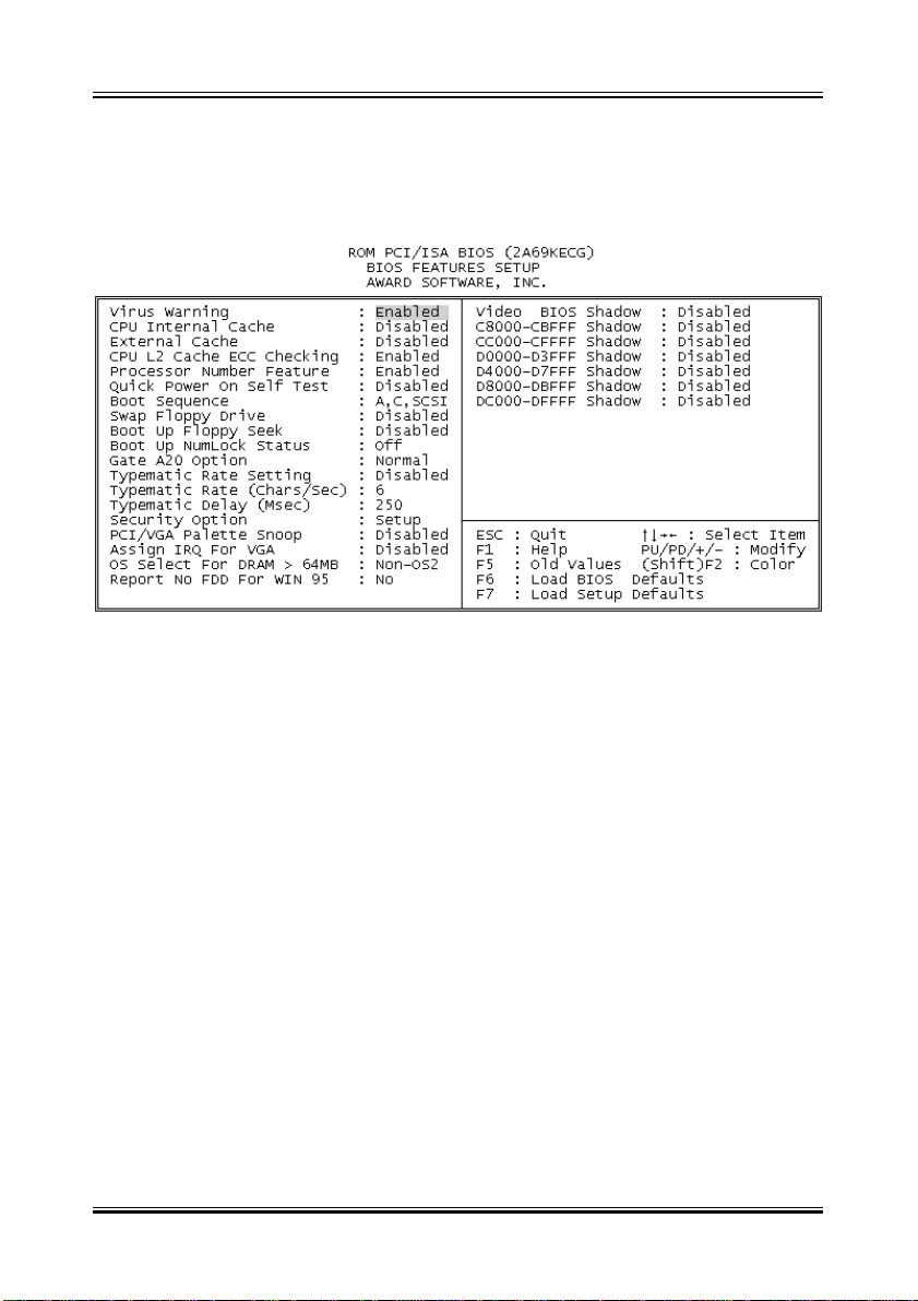
Appendix: BIOS SETUP TIPS
The document comes from the Award BIOS Manual, for reference only.
Virus Warning
When this item is enabled, the Award BIOS will monitor the boot sector and
partition table of the hard disk drive for any attempt at modification.Afterwards,
if necessary, you will be able to run an anti-virus program to locate and remove the problem before any damage is done.
Enabled Activates automatically when the system boots up causing
a warning message to appear when anything attempts to
access the boot sector or hard disk partition table.
Disabled No warning message will appear when anything attempts to
access the boot sector or hard disk partition table.
CPU Internal Cache/External Cache
These two categories speed up memory access. However, it depends on
CPU/chipset design. The default value is enable.
Enabled Enable cache
Disabled Disable cache
18
Page 19

Manual Rev. A
Quick Power On Self T est
This category speeds up Power On Self Test (POST) after you power up the
computer. If it is set to Enable, BIOS will shorten or skip some check items
during POST.
Enabled Enable quick POST
Disabled Normal POST
Boot Sequence
This category determines which drive to search first for the disk operating
system (i.e., DOS). Default value is A,C.
C,A First search for hard disk drive then floppy disk drive.
A,C First search for floppy disk drive then hard disk drive.
CDROM, C, A System will first search for CDROM drive, then hard disk drive
and the next is floppy disk drive.
C, CDROM, A System will first search for hard disk drive , then CDROM
drive, and the next is floppy disk drive.
Swap Floppy Drive
This item allows you to determine whether enable the swap floppy drive or
not. The choice: Enabled/Disabled.
Boot Up Floppy Seek
During POST, BIOS will determine if the floppy disk drive installed is 40 or 80
tracks. 360K type is 40 tracks while 760K, 1.2M and 1.44M are all 80 tracks.
Enabled BIOS searches for floppy disk drive to determine if it is 40 or
80 tracks. Note that BIOS can not tell from 720K, 1.2M or
1.44M drive type as they are all 80 tracks.
Disabled BIOS will not search for the type of floppy disk drive by track
number.
Boot Up NumLock Status
This allows you to determine the default state of the numeric keypad. By
default, the system boots up with NumLock on.
On Keypad is number keys
Off Keypad is arrow keys
19
Page 20

Manual Rev. A
Boot Up System Speed
Selects the default system speed — the normal operating speed at power up.
High: Set the speed to high Low: Set the speed to low
Gate A20 Option
This entry allows you to select how the gate A20 is handled. The gate A20 is
a device used to address memory above 1 Mbytes. Initially , the gate A20 was
handled via a pin on the keyboard. Today, while keyboards still provide this
support, it is more common, and much faster, for the system chipset to provide support for gate A20.
Normal keyboard
Fast chipset
T ypematic Rate Setting
This determines if the typematic rate is to be used. When disabled, continually holding down a key on your keyboard will generate only one instance. In
other words, the BIOS will only report that the key is down. When the typematic
rate is enabled, the BIOS will report as before, but it will then wait a moment,
and, if the key is still down, it will begin the report that the key has been depressed repeatedly . For example, you would use such a feature to accelerate
cursor movements with the arrow keys.
Enabled Enable typematic rate
Disabled Disable typematic rate
T ypematic Rate (Chars/Sec)
When the typematic rate is enabled, this selection allows you select the rate at
which the keys are accelerated.
T ypematic Delay (Msec)
When the typematic rate is enabled, this selection allows you to select the
delay between when the key was first depressed and when the acceleration
begins.
Security Option
This category allows you to limit access to the system and Setup, or just to
Setup
20
Page 21

Manual Rev. A
OS Select for DRAM > 64
This item allows you to access the memory that over 64MB in OS/2.
The choice: Non-OS2, OS2.
PCI / VGA Palette Snoop
It determines whether the MPEG ISA/VESA VGA Cards can work with PCI/
VGA or not.
Enabled When PCI/VGA working with MPEG ISA/VESA VGA Card.
Disabled When PCI/VGA not working with MPEG ISA/VESA VGA Card
Video BIOS Shadow
Determines whether video BIOS will be copied to RAM. However, it is optional depending on chipset design. Video Shadow will increase the video
speed.
Enabled Video shadow is enabled
Disabled Video shadow is disabled
C8000 - CBFFF Shadow/DC000 - DFFFF Shadow
These categories determine whether option ROMs will be copied to RAM. An
example of such option ROM would be support of on-board SCSI.
Enabled Optional shadow is enabled
Disabled Optional shadow is disabled
21
Page 22
Manual Rev. A
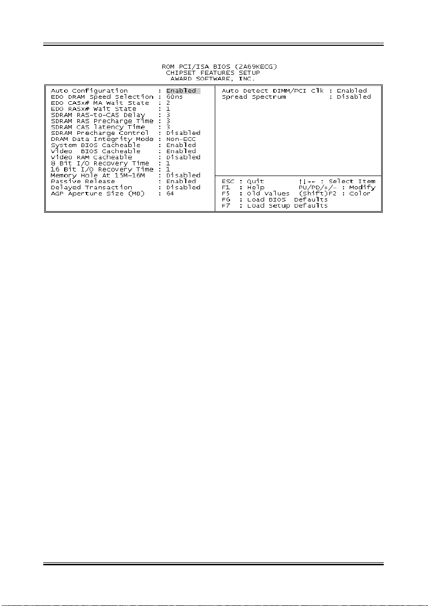
The Chipset Features Setup” includes settings for the chipset dependent
features. These features are related to system performance. It is highly
recommended that the items are optimal setting for this Main-Board. Y ou should
not change them unless you are familiar with the chipset. Make sure you fully
understand the items before you try to change anything. Y ou may change the
parameter settings to improve system performance. However, it may cause
system unstable if the settings are not correct for your system configuration.
Once you change the setting and not sure which one will be better parameter,
please load the BIOS default by press F6 or load the SETUP default by press
F7.
SDRAM RAS-to-CAS delay
They are important parameters that affect the SDRAM performance. If your
SDRAM has unstable problem, change 2/2 to 3/3.
SDRAM CAS Latency Time
This setting defines the CAS timing parameter of the SDRAM in terms of
clocks. Sometime, the BIOS will recommend you to set the correct value
depending on the DIMM Module you use.
22
Page 23

Manual Rev. A
System BIOS Cacheable
Select Enabled allows caching of the system BIOS ROM at F000h-FFFFFh,
resulting in better system performance. However, if any program writes to this
memory area, a system error may result.
Enabled BIOS access cached
Disabled BIOS access not cached
Video BIOS Cacheable
Select Enabled allows caching of the video BIOS ROM at C0000h-F7FFFh,
resulting in better video performance. However, if any program writes to this
memory area, a system error may result.
Enabled Video BIOS access cached
Disabled Video BIOS access not cached
Video RAM Cacheable
Select Enabled allows caching of the video RAM , resulting in better system
performance. However, if any program writes to this memory area, a system
error may result.
8 Bit I/O Recovery Time
The recovery time is the length of time, measured in CPU clocks, which the
system will delay after the completion of an input/output request. This delay
takes place because the CPU is operating so much faster than the input/
output bus that the CPU must be delayed to allow for the completion of the I/
O. This item allows you to determine the recovery time allowed for 8 bit I/O.
Choices are from NA, 1 to 8 CPU clocks.
16 Bit I/O Recovery Time
This item allows you to determine the recovery time allowed for 16 bit I/O.
Choices are from NA, 1 to 4 CPU clocks.
Memory Hole At 15M-16M
In order to improve performance, certain space in memory can be reserved
for ISA cards. This memory must be mapped into the memory space below
16 MB.
Enabled Memory hole supported.
Disabled Memory hole not supported.
23
Page 24

Manual Rev. A
Passive Release
When Enabled, CPU to PCI bus accesses are allowed during passive release. Otherwise, the arbiter only accepts another PCI master access to local
DRAM. The Choice: Enabled, Disabled.
Delayed Transaction
The chipset has an embedded 32-bit posted write buffer to support delay transactions cycles. Select Enabled to support compliance with PCI specification
version 2.1. The Choice: Enabled, Disabled.
AGP Aperture Size (MB)
Select the size of the Accelerated Graphics Port (AGP) aperture. The aperture is a portion of the PCI memory address range dedicated for graphics
memory address space. Host cycles that hit the aperture range are forwarded
to the AGP without any translation. See www.agpforum.org for AGP information. The choice: 4, 8, 16, 32, 64, 128, 256
24
Page 25
Manual Rev. A
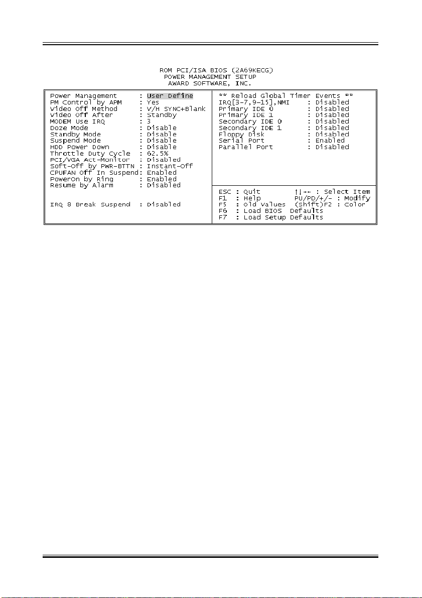
The Power Management Setup screen enables you to control the Main Board
green features.
Power Management
This function allows you to set the default parameters of power-saving modes.
PM Control by APM
If Max Saving” is selected, you can turn on this item, transfer power management control to APM
Video Off Method
The option V/H SYNC+Blank” allows the BIOS to blank off screen display by
turning off the V-Sync signals sent from add-on VGA card. DPMS Supported”
allows the BIOS to blank off screen display by your add-on VGA card which
supports DPMS; Blank Screen” allows the BIOS to blank screen display by
turning off the red-green-blue signals.
Video Off After
What time frame that the video will be disabled under current power management settings.
MODEM use IRQ
When the system is in green function, modem will wakes up the system through
IRQ you assigned here.
25
Page 26

Manual Rev. A
Doze Mode
When disabled, the system will not enter Doze mode. The specified time option defines the idle time the system takes before it enters Doze mode.
Standby Mode
When the standby mode timer times-out, it will enter the standby mode and
retain CPU at a slow working speed. The screen will be blanked out.
Suspend Mode
This function works only when the Pentium II Processor is installed. The timer
starts to count when system Standby mode timer is timed out and no PM
Events are occurring. V alid range is from 1 minute up to 1 hour.
HDD Power Down
This option lets you specify the IDE HDD idle time before the device enters
the power down state.
Throttle duty Cycle
Choose the duty cycle time : 12.5%, 25%, 37.5%, 50%, 62.5%(default), 75%,
or 87.5%. The bigger of the percentage, the more saving power it gets.
PCI/VGA Active Monitor
Enabled : the system can not enter the power saving mode when monitor is
on.
Disabled : the system can enter the power saving mode when monitor is on.
Soft-Off by PWRBTN
When enabled, turning the system off with the on/off button places the system
in a very low-power-usage state, with only enough circuitry receiving power to
detect power button activity or Resume by Ring activity .
Resume by Ring
Enabled : Wake up the system from ring signal ( COM Port )
Disabled : (default) Ring signal can not wake up the system.
Resume by Alarm:
his option allows you to have the system turn on at a preset time each day or
on a certain day .
26
Page 27

Manual Rev. A
RQ8 Break Suspend
Choose Enabled or Disabled (default). Alarm function will be activated when
this function is enabled.
Note:
If the [ Resume by Ring ] set to Enable, that means the machine will wake up
after a external Modem Ring in through the COM Port. That is the special
function for the Modem Ring on. But if the machine is in the off mode and you
just power ON/OFF the external Modem, sometimes, it will cause the machine power on, because the Modem Power On/OFF pulse will be taken as
the Modem Ring in signal and then power up the machine.
27
Page 28
Manual Rev. A
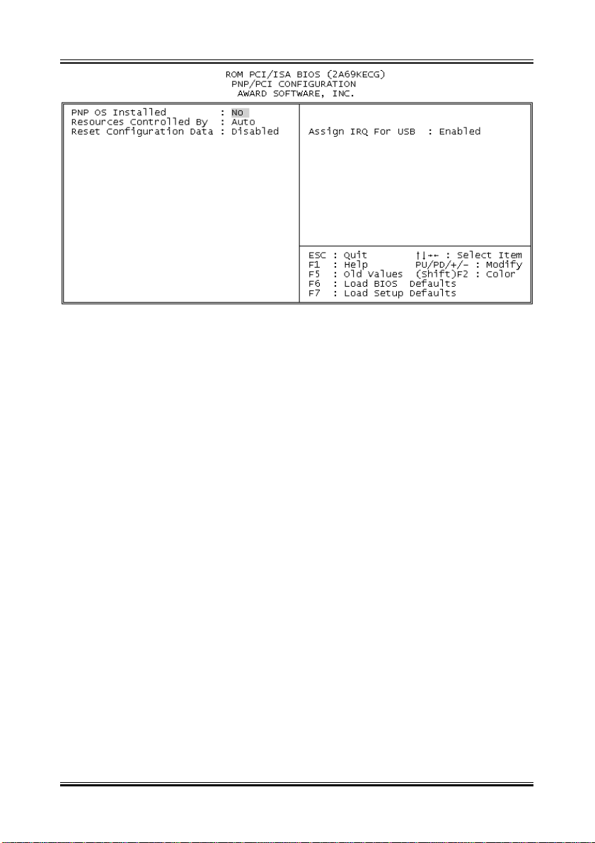
The PNP/PCI Configuration Setup allows you to configure the ISA and PCI
devices installed in your system.
PnP OS Installed
Normally , the PnP resources are allocated by BIOS during POST (Power-On
Self T est). If you are using a PnP operating system (such as Windows 95,98),
set this item to Y es to inform BIOS to configure only the resources needed for
booting (VGA/IDE or SCSI). The rest of system resources will be allocated by
PnP operating system.
Resources Controlled By
Setting this option to Manual allows you to individually assign the IRQs and
DMAs to the ISA and PCI devices. Set this to Auto to enable the auto-configuration function.
Reset Configuration Data
If you had plugged some Legacy cards in the system and there were records
into ESCD (Extended System Configuration Data). You can set this field to
Enabled to clear ESCD one time, while the Legacy cards were removed.
Assign IRQ For USB
Assign IRQ For USB
28
Page 29
Manual Rev. A
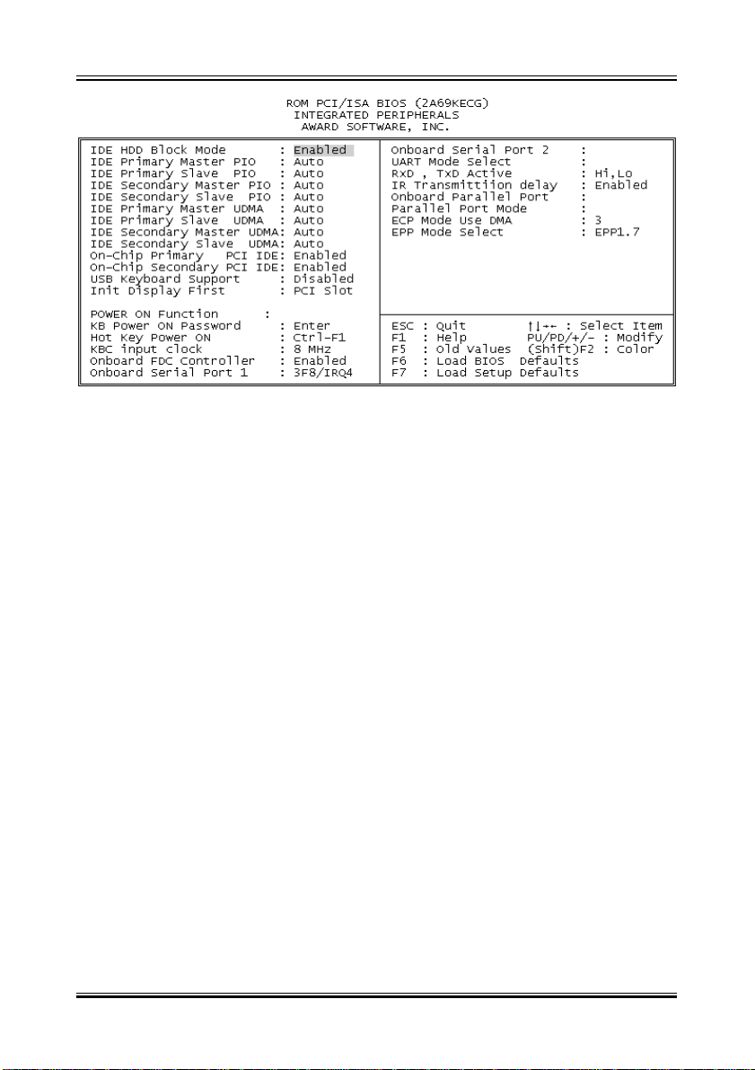
IDE HDD Block Mode
This allows your hard disk controller to use the fast block mode to transfer
data to and from your hard disk drive (HDD).
Enabled IDE controller uses block mode.
Disabled IDE controller uses standard mode.
IDE Primary/Secondary Master/Slave PIO
The four IDE PIO (Programmed Input/Output) fields let you set a PIO mode
(0-4) for each of the four IDE devices that the onboard IDE interface supports.
Modes 0 through 4 provide successively increased performance. In Auto mode,
the system automatically determines the best mode for each device.
IDE Primary/Secondary Master/Slave UDMA
Ultra DMA/33 implementation is possible only if your IDE hard drive supports
it and the operating environment includes a DMA driver (Windows 95 OSR2
or a third-party IDE bus master driver). If your hard drive and your system
software both support Ultra DMA/33, select Auto to enable BIOS support.
The Choice: Auto, Disabled
On-Chip Primary/Secondary PCI IDE
The integrated peripheral controller contains an IDE interface with support for
two IDE channels. Select Enabled to activate each channel separately .
29
Page 30

Manual Rev. A
USB Keyboard support
Select Enabled if your system contains a Universal Serial Bus (USB) controller and you have a USB keyboard.
The Choice: Enabled, Disabled.
Onboard FDD Controller
This should be enabled if your system has a floppy disk drive (FDD) installed
on the system board and you wish to use it. Even when so equipped, if you
add a higher performance controller, you will need to disable this feature.
The Choice: Enabled, Disabled.
Onboard Serial Port 1/Port 2
This item allows you to determine access onboard serial port 1/port 2 controller with which I/O address.
The Choice: 3F8/IRQ4, 2F8/IRQ3, 3E8/IRQ4, 2F8/IRQ3, Disabled, Auto.
UART 2 Mode
This item allows you to determine which Infra Red (IR) function of onboard I/O
chip. The Choice: Standard, ASKIR, HPSIR.
Duplex Select
Select the value required by the IR device connected to the IR port. Fullduplex mode permits simultaneous two-direction transmission. Half-duplex
mode permits transmission in one direction only at a time.
The Choice: Half, Full.
RxD, TxD Active
This item allows you to determine the active of RxD, TxD.
The Choice:Hi, Hi, Lo, Lo, Lo, Hi,Hi, Lo
Onboard Parallel Port
Select a logical LPT port name and matching address for the physical parallel
(printer) port.
The choice: 378H/IRQ7, 278H/IRQ5, 3BCH/IRQ7, Disabled.
30
Page 31
Manual Rev. A
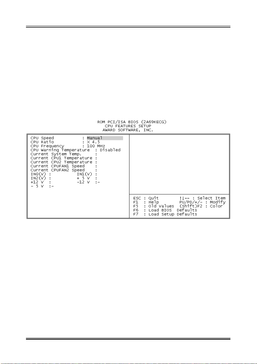
Parallel Port Mode
Select an operating mode for the onboard parallel port. Select Compatible or
Extended unless you are certain both your hardware and software support
EPP or ECP mode.
The choice: SPP, ECP+EPP1.7, EPP1.7+SPP, EPP1.9+SPP, ECP,
ECP+EPP1.9, and Normal.
ECP Mode Use DMA
Select a DMA channel for the port. Choices are 3, 1.
CPU Speed
Set to Manual user can use the next two items to decide the CPU speed.
CPU Ratio
This item lets you select the ratio of Core/Bus frequency . Have the following
selections: 3x, 3.5x, 4x , 4.5x, 5x, 5.5x, 6x
CPU Frequency
This item lets you set external clock (bus clock). The possible settings are 66,
75, 83, 100, 103, 1 12, 124, 133 MHZ.
CPU Warning Temperature
This is the temperature setting that the computer will respond to an overheating CPU and provide the alarm.
31
Page 32

Manual Rev. A
USER Password
This Main Menu item lets you configure the system so that a password is
required every time the system boots or an attempt is made to enter the Setup
program. The password cannot be longer than 8 characters.
IDE HDD Auto Detection
If your system has an IDE hard drive, you can use this utility to detect its
parameters and automatically enter them into the Standard CMOS Setup.
Normal mode
For drivers small than 528MB
Large Mode
For drives larger than 528MB that do not use LBA. There can only be used
with MS-Dos operating system.
LBA mode
For drivers larger than 528MB and up to 8.4GB that use logic block addressing mode. Normally we recommend to select LBA Mode if our HDD drivers
large than 528MB
SAVE & EXIT SETUP
-- END --
32
 Loading...