

Enpaix EFGS series User Manual
User’s Manual
Digital Force Gauge

Contents
1. Introduction
1.1 Overview 1
1.2 I ndicator 1
1.3 Load Cell 2
1.4 Specifications 3
2. Operation
2.1 Choose model 4
2.2 Measuring adapters 4
2.3 Power on/off 4
2.4 Testing 4
2.5 Storage 5
2.6 Browse and Printing 5
3. Menus
3.1 Menus Structure 6
3.2 Measurement 7
3.3 Memory 8
3.4 Printing 10
3.5 System Setting 11
4. Communications Ports
4.1 USB/Recharge 13
4.2 Multifunction port 13
5. Maintenance and Calibration
5.1 Charging 15
5.2 Calibration 15
6. Connecting Load Cell
6.1 Connection 17
6.2 Capacity Setup 17
Appendix
Packing List 18
Dimension 18
Warranty Card 19
1
1. Introduction
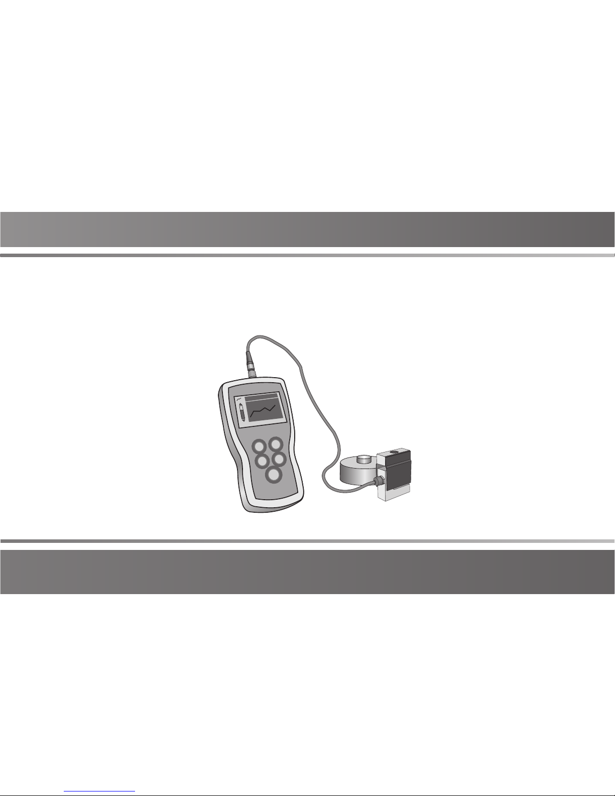
1.1 Overview
The force gauge consists of a force indicator and a load cell.
An indicator can be equipped with a few of load cells. Every
load cell can be calibrated independently, and indicator can
identify them automatically..
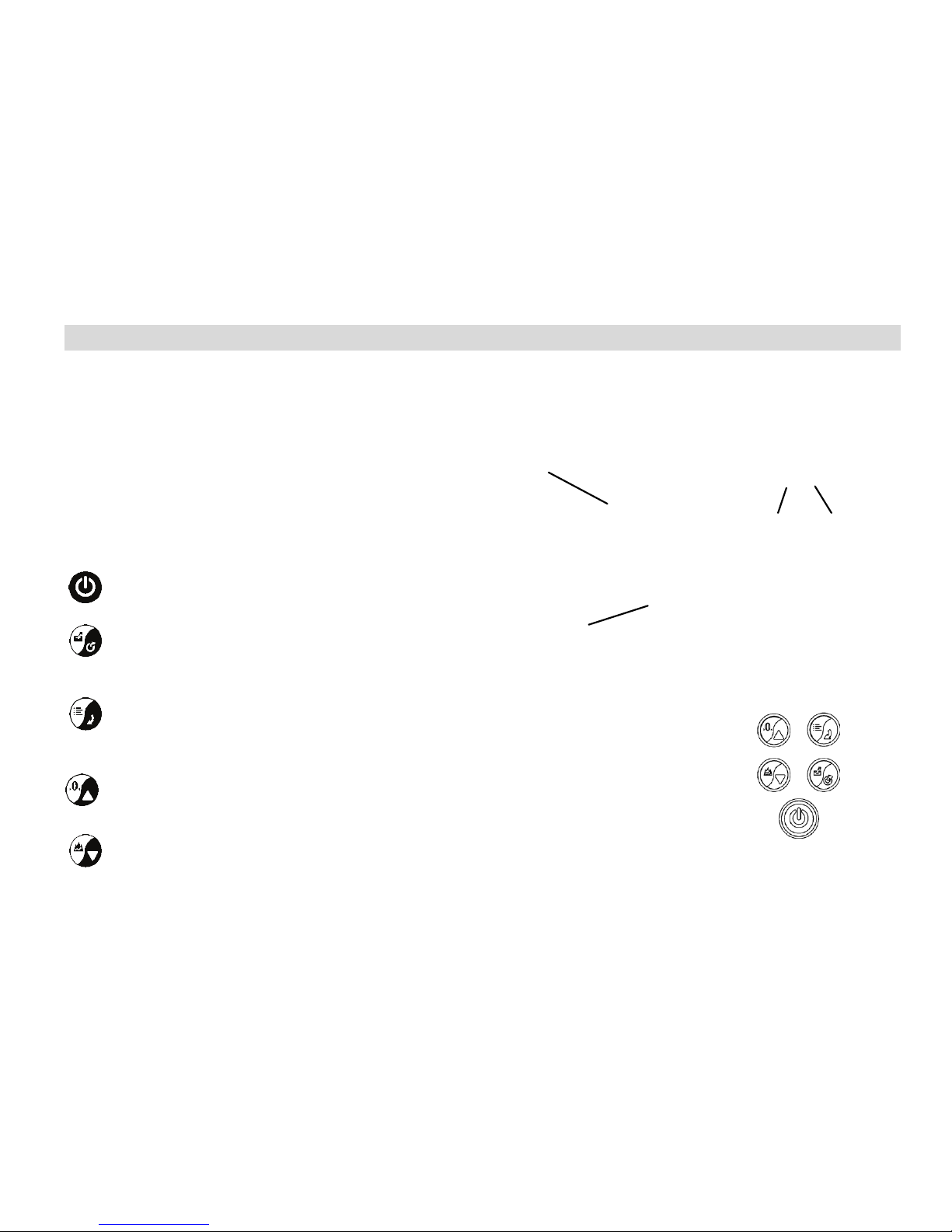
1.2 Indicator
1.2. 1 To uch P ad
Power
Push for 2 seconds to power On or Off.
Save/Exit
During Measurement: Print the current value or
store data, depending on the key setting.
In Menus: Back or Exit.
Menu/Enter
During Measurement: Enter the menus.
In Menus: Select or Enter.
Zeroing/Up
During Measurement: Zeroing.
In Menus: Moves selection up or increases the value.
Mode/Down
During Measurement: Changes Test Mode.
In Menus: Moves selection down or decreases the value.
Fig. 1-2
LCD Screen
Touch Pad
USB Multifunction
Port Port
Fig. 1-
1
Load Cell
Force Indicator
2
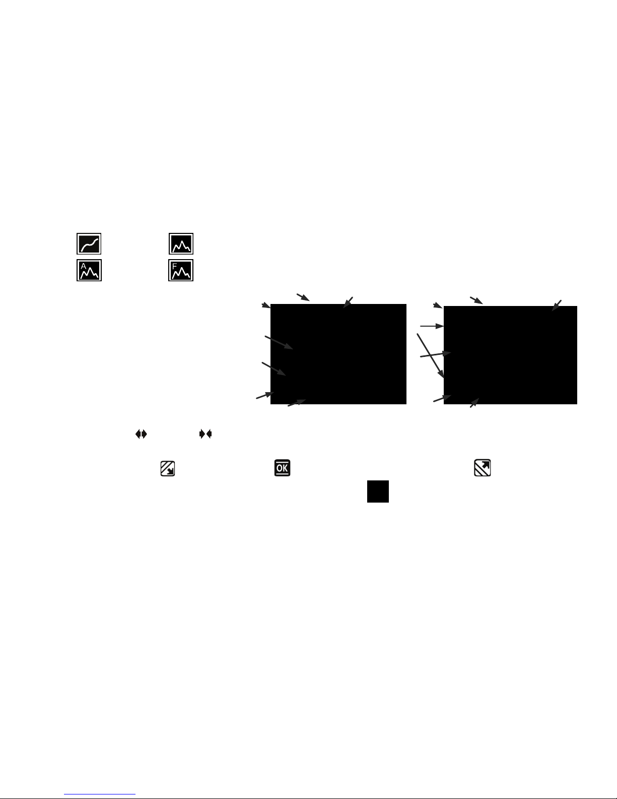
1.2.2 LCD Screen
❶ Test mode
Track, Peak,
Auto Peak, First
Peak
❷ Force val ue
❸ Analog bar: Indicates current position
in whole capacity. When the bar enters
the area enclosed by dotted line, means
overload.
❹ Saving icon: Indicates data is being
saved
❺ Direction Icon: “ ” tension, “ ”
compression.
❻ Tolerance Indicator: “ ”: under lower limit; “ ”: between lower limit and upper limit; “ ”: over upper limit.
❼ Load Cell: The capacity of load cell. If no load cell connecting, show " "and twinkling.
1.3 Load Cel l
There are 2 types of load cell can be connected with indicator, they are S-beam and ring type.
Fig. 1-3
❶
Data Display
Graphic Display
❷
❸
❹
❺
❶
❺
❹
❷
❸
❼
❼ ❻ ❻
3
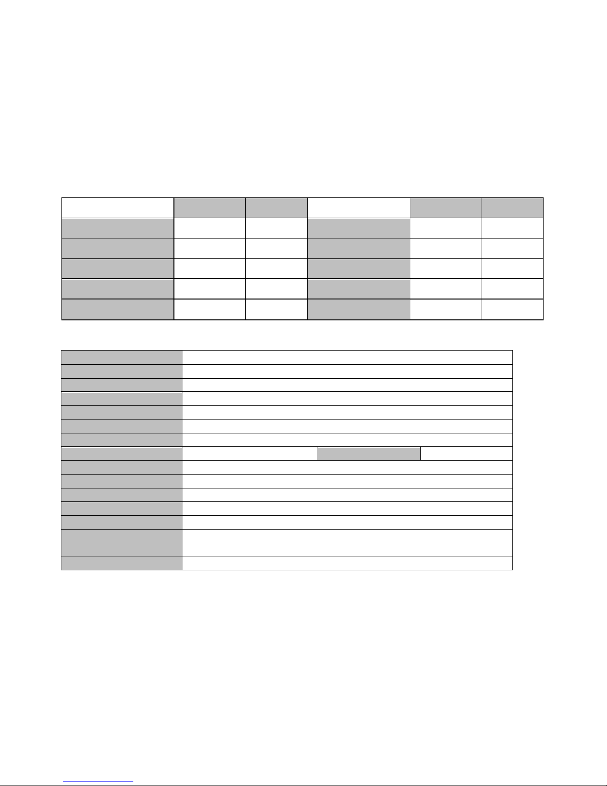
S-beam type Ring t ype
S-beam type Ring t ype
Rated Output(mV / V) 2.0±1 1.5±0.5 Safe Overload(F.S.) 150% 120%
Zero Balance(%F.S.) ±2 ±2 Input Impedance(Ω) 410±10 410±10
Non-linearity(%F.S.) 0.03 0.05~0.1 Output Impedance(Ω) 350±5 350±5
Hyst eresis(% F.S.) 0.03 0.05~0.1 Protection Class IP76 IP76
Temp. Effect(F.S./10ºC) 0.03 0.05%
1.4 Specifications
Accuracy
± 0.2% F.S.
Selectabl e Units N, kN, kgf, tf, lbf, klbf.(Selectable)
Display
160*128 dot matrix L CD with LE D Ba cklight
Overload
150% of F.S. (LCD flashes beyond 110% of F.S.)
Temperature Effects
<0.03% FS per °C
Measurement Mode Track, Peak, AutoPeak, FirstPeak
Set Poi nt
Tole rance Alarm
Sampling Rate 2000 Hz Display Update 10 times/sec.
Memory
1000 data
Power 3.6VDC Ni-MH rechargeable batteries
Battery Life
Approximately 12 hours continuous use per full charge
Charger / Adaptor Universal USB/BM c harger, Input:110~240VAC
Outputs
USB, RS232, Set points output
Environment
Operating: -10 to 40°C, 20 to 80% RH
Storage : -20 to +50°C , 5 to 95%RH
Accessories
AC adapter/charger

4
2. Operation
2.1 Choose model
This series has a variety of models can be selected, different models corresponding to different capacity and resolution,
as shown in table on back cover of this manual.
2.2 Choose measuring adapters
In order to complete the test work convenient, the force gauge equipped with a variety of adapters. Select the
appropriate adaptors according to the actual need.
2.3 Power on/off
Touch for 2 seconds to power On or Off.
The indicator can identify the load cell. You should check the model wheith it is you want.
Check Battery Icon. If the power is low, should be recharged.
2.4 Testing
2.4.1 Adaptor
Select the appropriate adaptor, install it in the measurement axis of the load cell. Tighten it by hand, without the use of
tools. Do not use a deformed or damaged adaptor.
NOTE: Do not use tools to vigorously tighten the adaptor, otherwise it will damage the force gauge.
2.4.2 Select Units
The force gauge has a variety of measurement units, select the appropriate unit of force. (See 3.2.1 Unit )
2.4.3 Select Test Mode
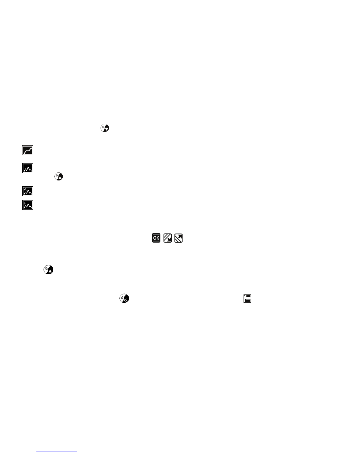
5
This series force gauge has 4 kinds of measurement test mode can choose.
You can select it by touching under the meas ure interface,
Or can change it in menus (See 3.2.4 Test Mode ).
Track: The real time measuring mode, under this mode, press the zero key the force gauge will be cleared
(remove tare).
Peak: Peak readings will not change until a higher value is measured. Under this mode, touch the zero key
the force gauge will update the display immediately.
Auto-Peak: In this mode, the gauge display a peak value of force in a fixed duration. The duration time can be
set in menus.
First Peak: In this mode, the gauge can capture the first peak value of force, when the force value decreased to
reach the drop ratio. The drop ratio can be set in menus.
2.4.4 Set Tolerance Limit
The tolerance limits can be set for GO/NG measurement also.
If you set the alarm on and a valid limit, The icon , , will be displayed for within limit, lower than lower limit
or exceed upper limit.
2.4.5 Zeroing
Touch to clear the force gauge in track mode for removing the tare.
2.5 St or age
Measured results can be stored in the force gauge, so that you can review or print them later.
Under the measure interface, touch to save value measured, and the save icon will be displayed.
2.6 Browse and Printing
The values saved in memory can be reviewed in Browse function, see 3.3.2 Browse Data for detail.
The data in memory can be printed to a report, see 3.4 Printing for detail.
 Loading...