

Enovation Controls Murphy-Link Series, Murphy ML100, Murphy ML50, Murphy ML25, Murphy ML300 Installation And Operation Manual
...Page 1
Murphy-Link Series Panels
Models ML25, ML50, ML100
ML150, and ML300
Installation and Operations Manual
00-02-0842
2013-12-17
Section 30
To order call 1-800-548-1191 or visit www.partdeal.com - info@partdeal.com
Page 2

In order to consistently bring you the highest quality, full featured products, we reserve the right to change our
specifications and designs at any time. The latest version of this manual can be found at www.fwmurphy.com.
BEFORE BEGINNING INSTALLATION OF THI S MURPHY
PRODUCT:
Read and follow all installation instructions.
Please contact Enovation Controls immediately if you have any
questions.
To order call 1-800-548-1191 or visit www.partdeal.com - info@partdeal.com
Page 3

Table of Contents
ML25 Panel .......................................................................................................................................... 1
ML50 Panel .......................................................................................................................................... 3
ML100 Panel ........................................................................................................................................ 5
ML150 Panel ........................................................................................................................................ 7
ML300 Panel ........................................................................................................................................ 9
To order call 1-800-548-1191 or visit www.partdeal.com - info@partdeal.com
Page 4

(THIS PAGE INTENTIONALLY LEFT BLANK)
To order call 1-800-548-1191 or visit www.partdeal.com - info@partdeal.com
Page 5
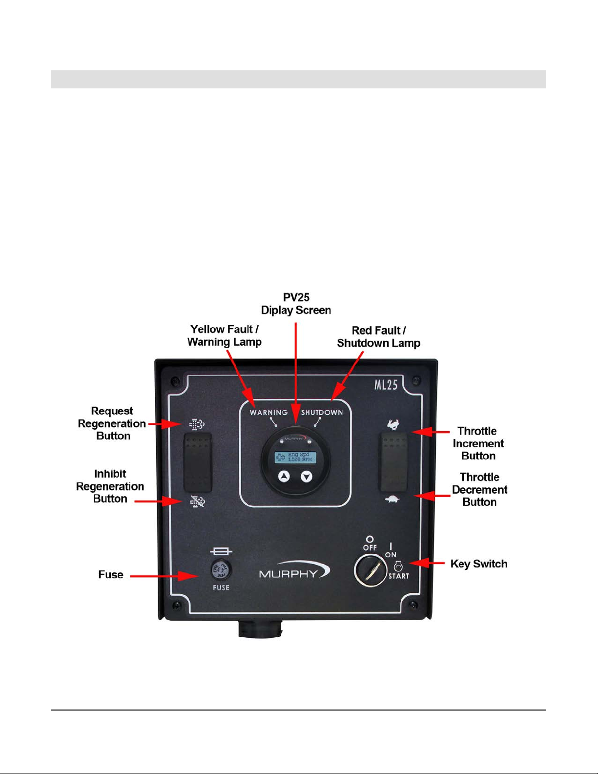
ML25 Panel
The MurphyLink® Series ML25 Panel f eat ur e s the Pow er Vi ew™ Model PV25 display. This
J1939-compliant device provides electronic engine parameter data, is simple to install, and
matches the PowerView line of rugged displays. The PV25 can be powered by 12 or 24 volt
systems.
The PV25 is equipped with two push buttons to quickly access a convenient menu. In addition,
a back-lit graphic display and two LED’s indicate Active-fault Alarm or Shutdown status.
Active and Stored Fault messages display the SPN (Suspect Parameter Number), FMI (Failure
Mode Indicator) and the OC (Occurrence Count) using the SAE J1939 protocol.
Please refer to the documents included within the panel shipment for the correct panel layout
and schematic.
Section 30 00-02-0842
2013-12-17 - 1 -
To order call 1-800-548-1191 or visit www.partdeal.com - info@partdeal.com
Page 6

Feature
Description
PowerView Model PV25 Display
For additional information on the PV25 display,
Yellow Fault/Warning Lamp
Indicates when a warning is present via CAN
Red Fault/Shutdown Lamp
Indicates when a shutdown is present via CAN
Request Regeneration Button
Allows the operator to send a request to engine to perform
Inhibit Regeneration Button
Allows the operator to send a message to the engine to
Throttle Increment Button
Allows the operator to throttle engine up via CAN
Throttle Decrement Button
Allows the operator to throttle engine down via CAN
Key Swi tch
Operator initiated cranking of engine via turning the key to
refer to “00-02-0839 - PV25-Installation and Operations”
manual.
communications.
communications.
an active regeneration.
inhibit the engine from performing an active regeneration.
communication utilizing TSC1 capabilities. Takes operator
to ‘Desired Engine Speed’ screen when pressed.
(Increment “Bump” = 25RPM, default adjustable;
Ramp Up “Hold” = 200RPM, default adjustable)
communication utilizing TSC1 capabilities. Takes operator
to ‘Desired Engine Speed’ screen when pressed.
(Decrement “Bump” = 25RPM, default adjustable;
Ramp Down “Hold” = 200RPM, default adjustable)
crank state.
Section 30 00-02-0842
2013-12-17 - 2 -
To order call 1-800-548-1191 or visit www.partdeal.com - info@partdeal.com
Page 7

ML50 Panel
The MurphyLink® Series ML50 Panels feature PVCAN gages and the PowerView™ Model
PV25 display. This J1939-compliant device provides electronic engine parameter data, is
simple to install, and matches the PowerView line of rugged displays. The PV25 can be
powered by 12 or 24 volt systems.
The PV25 is equipped with two push buttons to quickly access a convenient menu. In addition,
a back-lit graphic display and two LED’s indicate Active-fault Alarm or Shutdown status.
Active and Stored Fault messages display the SPN (Suspect Parameter Number), FMI (Failure
Mode Indicator) and the OC (Occurrence Count) using the SAE J1939 protocol.
Please refer to the documents included within the panel shipment for the correct panel layout
and schematic.
Section 30 00-02-0842
2013-12-17 - 3 -
To order call 1-800-548-1191 or visit www.partdeal.com - info@partdeal.com
Page 8

Feature
Description
PowerView Model PV25 Display
For additional information on the PV25 display, refer to
Yellow Fault/Warning Lamp
Indicates when a warning is present via CAN
Red Fault/Shutdown Lamp
Indicates when a shutdown is present via CAN
Request Regeneration Button
Allows the operator to send a request to engine to perform
Inhibit Regeneration Button
Allows the operator to send a message to the engine to
Throttle Increment Button
Allows the operator to throttle engine up via CAN
Throttle Decrement Button
Allows the operator to throttle engine down via CAN
Key Swi tch
Operator initiated cranking of engine via turning the key to
“00-02-0839 - PV25-Installation and Operations” manual.
communications.
communications.
an active regeneration.
inhibit the engine from performing an active regeneration.
communication utilizing TSC1 capabilities. Takes operator
to ‘Desired Engine Speed’ screen when pressed.
(Increment “Bump” = 25RPM, default adjustable;
Ramp Up “Hold” = 200RPM, default adjustable)
communication utilizing TSC1 capabilities. Takes operator
to ‘Desired Engine Speed’ screen when pressed.
(Decrement “Bump” = 25RPM, default adjustable;
Ramp Down “Hold” = 200RPM, default adjustable)
crank state.
Section 30 00-02-0842
2013-12-17 - 4 -
To order call 1-800-548-1191 or visit www.partdeal.com - info@partdeal.com
Page 9
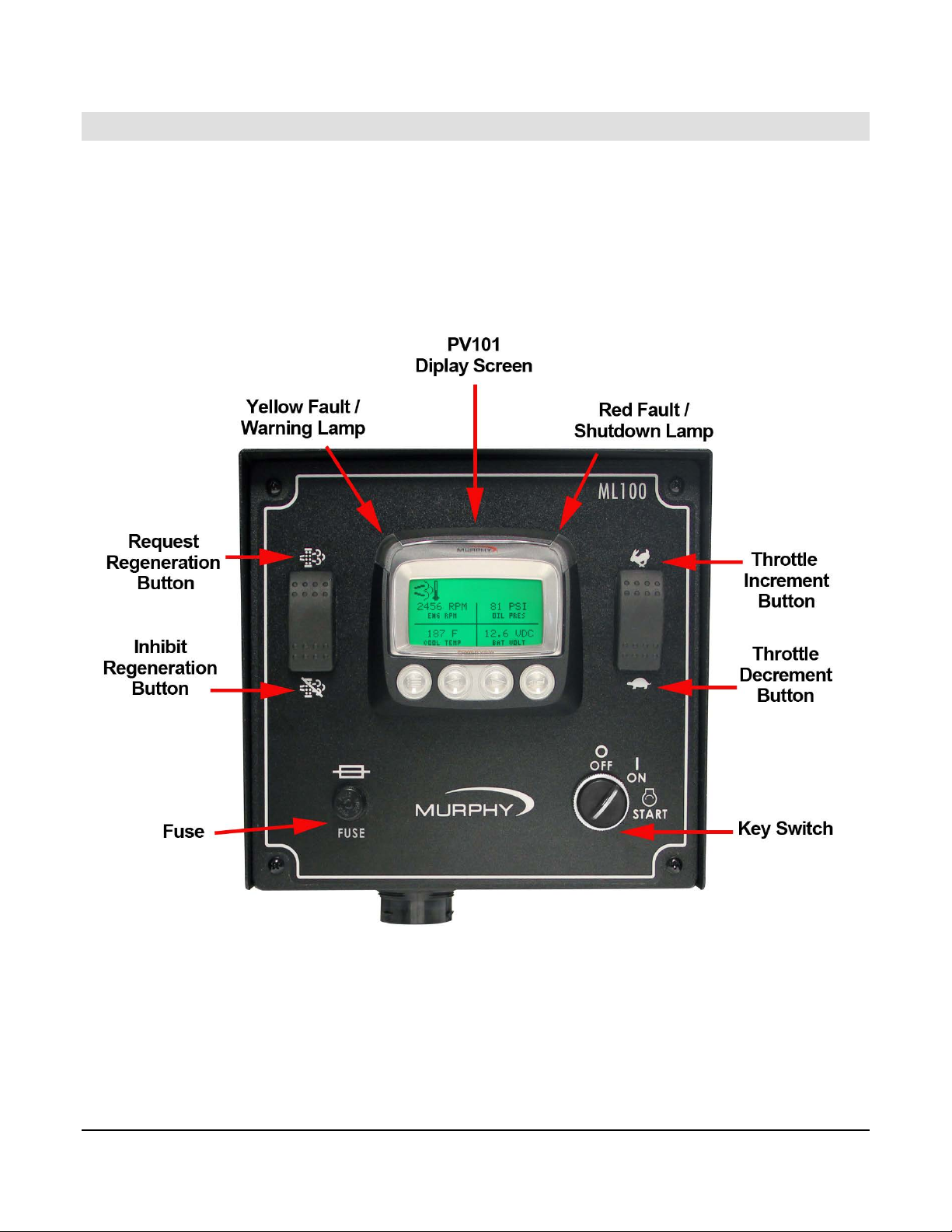
ML100 Panel
The MurphyLink® Series ML100 Panel features the PowerView Model PV101-C display, a
key switch, and increment/decrement throttle. The PV101 Display is a multifunction tool that
enables equipment operators to view many different engine or transmission parameters and
service codes.
Please refer to the documents included within the panel shipment for the correct panel layout
and schematic.
Section 30 00-02-0842
2013-12-17 - 5 -
To order call 1-800-548-1191 or visit www.partdeal.com - info@partdeal.com
Page 10

Feature
Description
PowerView Model PV101-C Display
For additional information on the PV101-C display, refer to
Yellow Fault/Warning Lamp
Indicates when a warning is present via CAN
Red Fault/Shutdown Lamp
Indicates when a shutdown is present via CAN
Request Regeneration Button
Allows the operator to send a request to engine to perform
Inhibit Regeneration Button
Allows the operator to send a message to the engine to
Throttle Increment Button
Allows the operator to throttle engine up via CAN
Throttle Decrement Button
Allows the operator to throttle engine down via CAN
Key Swi tch
Operator initiated cranking of engine via turning the key to
“00-02-0796 – PV101-C-v3.2 -Installation and Operations”
manual.
communications.
communications.
an active regeneration.
inhibit the engine from performing an active regeneration.
communication utilizing TSC1 capabilities. Takes operator
to ‘Desired Engine Speed’ screen when pressed.
(Increment “Bump” = 25RPM, default adjustable;
Ramp Up “Hold” = 200RPM, default adjustable)
communication utilizing TSC1 capabilities. Takes operator
to ‘Desired Engine Speed’ screen when pressed.
(Decrement “Bump” = 25RPM, default adjustable;
Ramp Down “Hold” = 200RPM, default adjustable)
crank state.
Section 30 00-02-0842
2013-12-17 - 6 -
To order call 1-800-548-1191 or visit www.partdeal.com - info@partdeal.com
Page 11

ML150 Panel
The MurphyLink® Series ML150 Panels include the PowerView PV101-C Display and the
M-Link™ PowerView Analog Gages. The PV101 Display is a multifunction tool that enables
equipment operators to view many different engine or transmission parameters and service
codes. M-Link PowerView Analog Gages display critical engine data broadcast by an
electronic engine: eng ine RPM , oi l pressur e, and coolant temperatu r e.
Please refer to the documents included within the panel shipment for the correct panel layout
and schematic.
Section 30 00-02-0842
2013-12-17 - 7 -
To order call 1-800-548-1191 or visit www.partdeal.com - info@partdeal.com
Page 12

Feature
Description
PowerView Model PV101-C Display
For additional information on the PV101-C display, refer to
Yellow Fault/Warning Lamp
Indicates when a warning is present via CAN
Red Fault/Shutdown Lamp
Indicates when a shutdown is present via CAN
Request Regeneration Button
Allows the operator to send a request to engine to perform
Inhibit Regeneration Button
Allows the operator to send a message to the engine to
Throttle Increment Button
Allows the operator to throttle engine up via CAN
Throttle Decrement Button
Allows the operator to throttle engine down via CAN
Key Swi tch
Operator initiated cranking of engine via turning the key to
Remote Stop Switch
Operator initiated switch. Push to shutdown engine. Pull to
“00-02-0796 – PV101-C-v3.2 -Installation and Operations”
manual.
communications.
communications.
an active regeneration.
inhibit the engine from performing an active regeneration.
communication utilizing TSC1 capabilities. Takes operator
to ‘Desired Engine Speed’ screen when pressed.
(Increment “Bump” = 25RPM, default adjustable;
Ramp Up “Hold” = 200RPM, default adjustable)
communication utilizing TSC1 capabilities. Takes operator
to ‘Desired Engine Speed’ screen when pressed.
(Decrement “Bump” = 25RPM, default adjustable;
Ramp Down “Hold” = 200RPM, default adjustable)
crank state.
enable cranking via key switch.
Section 30 00-02-0842
2013-12-17 - 8 -
To order call 1-800-548-1191 or visit www.partdeal.com - info@partdeal.com
Page 13

ML300 Panel
The MurphyLink® Series ML300 Panels include the new PowerView™ Model PV300 display
that provides advanced monitoring of electronic engines designed to meet Tier 4/Euro Stage
IV emissions requirements. The model PV300-P monitors multiple engine and machine
parameters on an easy-to-read 3.8-inch (97 mm) QVGA monochrome LCD.
Please refer to the documents included within the panel shipment for the correct panel layout
and schematic.
Section 30 00-02-0842
2013-12-17 - 9 -
To order call 1-800-548-1191 or visit www.partdeal.com - info@partdeal.com
Page 14

Feature
Description
PowerView Model PV300 Display
For additional information on the PV300-P display, refer to
Yellow Fault/Warning Lamp
Indicates when a warning is present via CAN
Red Fault/Shutdown Lamp
Indicates when a shutdown is present via CAN
Request Regeneration Button
Allows the operator to send a request to engine to perform
Inhibit Regeneration Button
Allows the operator to send a message to the engine to
Throttle Increment Button
Allows the operator to throttle engine up via CAN
Throttle Decrement Button
Allows the operator to throttle engine down via CAN
Key Swi tch
Operator initiated cranking of engine via turning the key to
Home Button
Allows operator to toggle through screens and exit the
Arrow Left Button
Allows operator to scroll through faults on gage screens
Arrow Right Button
Allows operator to scroll through faults on gage screens
Enter Button
Allows operator to select settings within the setting screen
“00-02-0834 – PV300-P -Installation and Operations”
manual.
communications.
communications.
an active regeneration.
inhibit the engine from performing an active regeneration.
communication utilizing TSC1 capabilities. Takes operator
to ‘Desired Engine Speed’ screen when pressed.
(Increment “Bump” = 25RPM, default adjustable;
Ramp Up “Hold” = 200RPM, default adjustable)
communication utilizing TSC1 capabilities. Takes operator
to ‘Desired Engine Speed’ screen when pressed.
(Decrement “Bump” = 25RPM, default adjustable;
Ramp Down “Hold” = 200RPM, default adjustable)
crank state.
settings of the display without saving changes.
and settings once in the ‘Settings’ screen.
and settings once in the ‘Settings’ screen.
for adjustability and saving.
Section 30 00-02-0842
2013-12-17 - 10 -
To order call 1-800-548-1191 or visit www.partdeal.com - info@partdeal.com
Page 15

THIS PAGE INTENTIONALY LEFT BLANK
Section 30 00-02-0842
2013-12-17 - 11 -
To order call 1-800-548-1191 or visit www.partdeal.com - info@partdeal.com
Page 16

To order call 1-800-548-1191 or visit www.partdeal.com - info@partdeal.com
 Loading...