

Enovation Controls Murphy DF Series, Murphy DF755, Murphy DF757 Installation And Operation Manual
Page 1
DF Series Hydrostatic Head Level
Switches
Installation and Operations Manual
00-02-0831
2013-03-21
Section 15
1-800-548-1191 - http://www.partdeal.com - info@partdeal.com
Page 2

In order to consistently bring you the highest quality, full featured products, we reserve the right to change our
specifications and designs at any time. The latest version of this manual can be found at www.fwmurphy.com.
Please read the following information before installing.
BEFORE BEGINNING INSTALLATION OF THIS MURPHY
PRODUCT:
Read and follow all installation instructions.
Please contact Enovation Controls immediately if you have any
questions.
1-800-548-1191 - http://www.partdeal.com - info@partdeal.com
Page 3

Table of Contents
Table of Contents ...................................................................................................................... iii
Introduction ................................................................................................................................. 1
Basic Operation ............................................................................................................1
Typical Applications .................................................................................................................. 3
Water Flood Control Systems ......................................................................................3
Low Pressure Gas Blanket on Tank .............................................................................3
Typical Wiring Diagrams ..............................................................................................4
Installation of a Volume Air Cell ............................................................................................... 6
Overview ......................................................................................................................6
Specifications ............................................................................................................................. 8
Service Parts ................................................................................................................9
1-800-548-1191 - http://www.partdeal.com - info@partdeal.com
Page 4

(THIS PAGE INTENTIONALLY LEFT BLANK)
1-800-548-1191 - http://www.partdeal.com - info@partdeal.com
Page 5
Introduction
The DF series are diaphragm-operated ‘hydrostatic head pressure’ level switches. A pressure
sensitive diaphragm operates a snap-switch that can be wired directly to electric pilot circuits to
control pumps at pre-determined levels. A typical application is starting and stopping electric
driven pump(s) to maintain tank levels. This series of level switches can also be used with
engine driven pumps.
The nitrile sensing-diaphragm is impervious to most liquids and is sensitive enough to control
levels with ¼ in. (6 mm) repeatability. See the next section, Basic Operation, for limits of
switch trip-point adjustability. The case is aluminum with a glass-filled nylon bottom plate.
This is a highly reliable level switch and can be worked into almost any new or existing system
without major modification or special tools.
The DF755 and DF757 are suitable for atmospheric tanks in non-hazardous areas. The SPDT
snap-switch for the DF755 is preset for a 4 in. (102 mm) differential in liquid level. The DF757
trip point is adjustable over a 108 in. (2743 mm) range.
Basic Operation
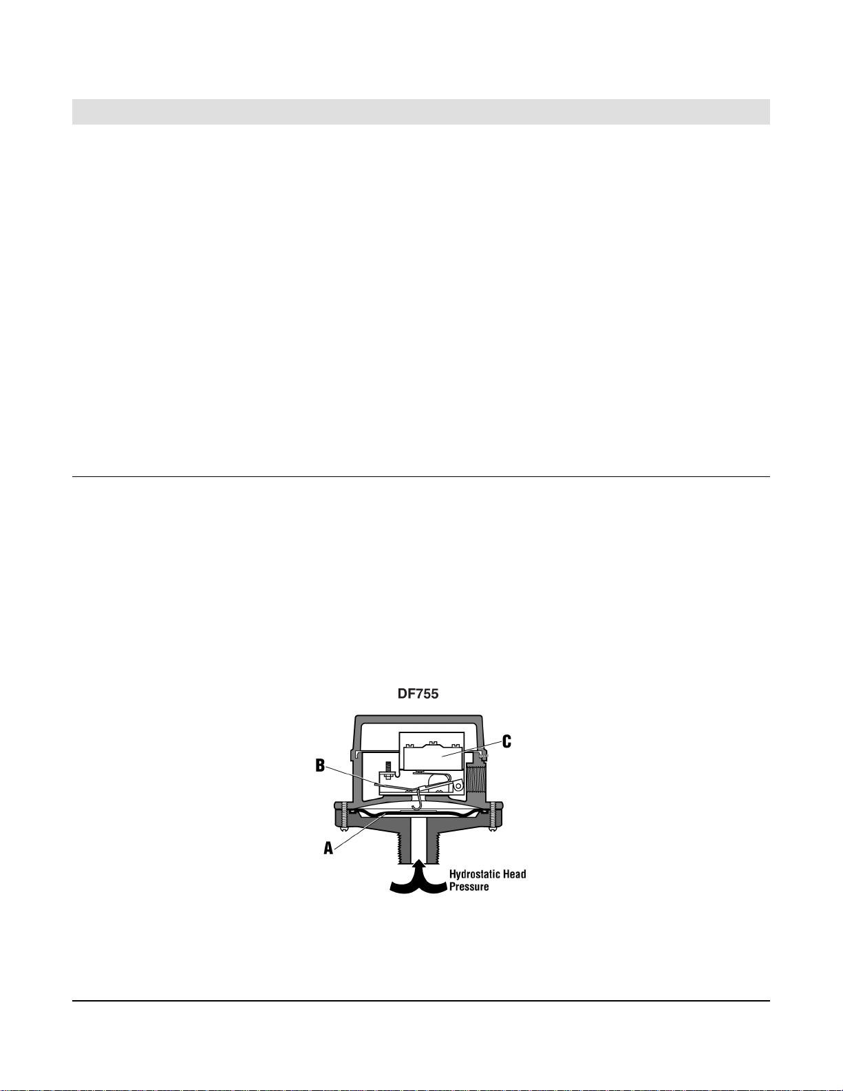
As the liquid level rises, hydrostatic head pressure is applied to the diaphragm (A) as shown
below. The diaphragm moves upward pressing the actuator arm (B) to activate the snapswitch (C).
Model DF755 is factory set and operates at approximately 2 in. (51 mm) and 6 in. (152 mm)
above the level at which the diaphragm is mounted. The trip point(s) for Model DF757 are
adjustable between 2 in. (51 mm) and 110 in. (2794 mm) for high and low (make/break)
operation by knobs (D).
Section 15 00-02-0831
2013-03-21 - 1 -
1-800-548-1191 - http://www.partdeal.com - info@partdeal.com
Page 6

Set Point Adjustment for the DF757
Locate the threaded adjustment shaft and adjustment knobs (see the
1.
following drawings).
To increase the low-level set point, rotate the lower knob
2.
counterclockwise.
NOTE: If the adjustment shaft turns when rotating the adjustment knobs,
firmly grasp the adjustment shaft with a pair of needle nose pliers, and
then rotate the knob.
Section 15 00-02-0831
2013-03-21 - 2 -
1-800-548-1191 - http://www.partdeal.com - info@partdeal.com
Page 7

Typical Applications
This section covers some general situations where the rugged DF Series switches provide a
simple-to-install solution. Applications include:
Water Flood Systems Diesel Day Tanks
Crude Oil Tanks Sumps
Salt Water Disposal Systems Cooling Towers
Water Flood Control Systems
The diagram below displays eight DF Series switches installed on Raw Water and Clear Water
tanks. When raw water rises to a predetermined level, DF#1 stops the supply pump. As tank
level falls below the set level, DF#2 starts the supply pump. If the tank level continues to fall,
DF#3 initiates a shutdown of the supply pump. DF#4 stops the transfer pump before the raw
water tank is completely pumped out.
When clear water reaches the predetermined level, DF#5 stops the transfer pump. As tank
level falls to the set low level, DF#6 starts the transfer pump. If the tank level continues to fall
due to the failure of the filters section, DF#7 initiates shutdown of the transfer pump. (A DF755
located at this level will also operate backwash equipment). DF#8 stops the injection pump
before tank pumps completely out. An OPL Series Pressure SWICHGAGE® stops the injection
pump when pressure reaches an established high or low pressure.
Low Pressure Gas Blanket on Tank
The level switches shown at right are installed
on a crude oil tank where a low-pressure gas
blanket is used to prevent evaporation loss.
The switches are mounted directly to the side
of the tank (or can be mounted on a riser pipe
4 to 7” [102 to 178 mm] below the level to be
controlled). The pump automatically stops or
starts when the gas liquid reaches
predetermined high or low level.
Section 15 00-02-0831
2013-03-21 - 3 -
1-800-548-1191 - http://www.partdeal.com - info@partdeal.com
Page 8

Typical Tank Mounting
The following graphics show different methods of mounting DF755 switches in tank
applications.
Typical Wiring Diagrams
Presented as an assist to wiring typical DF Series level switches.
Starts at Low Level, Stops at
High – Start motor when pre-
determined low level is reached
and stop when high level is
reached. Keeps tank level within
selected limits. Motor starter is
equipped with Hands Off Auto
(HOA).
Starts at High Level, Stops at
Low – Start motor when pre-
determined high level is
reached, and stop when low
level is reached. Motor starter
equipped with HOA.
Section 15 00-02-0831
2013-03-21 - 4 -
1-800-548-1191 - http://www.partdeal.com - info@partdeal.com
Page 9

Single Magneto Shutdown –
Wiring of magneto to Normally
Open (NO) switch terminal shuts
engine down at a pre-determined
high level (Shown at right). Wire
to Normally Closed (NC) terminal
to shutdown on low level.
Dual Magneto Shutdown –
Shutdown dual magneto engines
using a Murphy MS2120
Magnetic Switch. Diagram at
right shows hookup for low-level
shutdown. Wiring changes and
mounting locations are
necessary for high-level
shutdowns.
Section 15 00-02-0831
2013-03-21 - 5 -
1-800-548-1191 - http://www.partdeal.com - info@partdeal.com
Page 10

Installation of a Volume Air Cell
This section provides installation and
operation information for using a DF755 level
switch with a Murphy MAC1 Volume Air
Cell.
Overview
When attached to the DF755 level switch, the MAC1 Volume Air Cell can monitor water levels
on a sump, activate alarms, or start a pump directly. The MAC1 Volume Air Cell is noncorrosive. Stainless steel ¼-20 mounting studs are provided with the unit.
The MACT1 Tubing Kit provides 4 ft (1.2 m) of flexible, non-corrosive ¼ in (6 mm) tubing (cut
to fit). The kit also includes fittings necessary to attach tubing
Volume Cell Operation
As liquid rises around the volume cell, it compresses the air inside the cell and forces it up in
the sensor line. As the water level continues to rise, the air pressure increases. In time
sufficient pressure is applied to activate the internal snap-switch, this starts the pump. As the
liquid level is pumped down, pressure decreases, the snap-switch reverses and the pump
stops. The pump is held in a standby condition. An air purge may be required in the sensor
line. For additional information, consult Enovation Controls.
Choosing a Volume Cell
The volume cell should be constructed of material which will be unaffected by the liquid being
measured. For proper pressure to level ratio, the minimum dimensions of the volume cell
should be 6 inches (152 mm) inside diameter and 3 inches (76 mm) inside depth. The sensor
line can be of any diameter or material either flexible or solid, as long as it is of sufficient length
to reach from the volume cell to the desired location for the DF755. All fittings and connections
should be airtight to avoid loss of charge. Tube lengths longer than 4 ft (1.2m) should have a
provision for intermittent air purging.
Section 15 00-02-0831
2013-03-21 - 6 -
1-800-548-1191 - http://www.partdeal.com - info@partdeal.com
Page 11

Installation of the Volume Cell
Install the volume cell with reference to the level at which you wish the pump to start and stop.
Secure the volume cell with a substantial bracket that will not allow the cell to float or tilt when
the water level rises. Install the DF755 well above the highest water level and in a position that
allows access for adjustment or repairs.
NOTE: Periodically operate the pump manually until the water level
reaches a point approximately ½ in (13mm) below the bottom of the
Volume Cell. This automatically recharges the unit, and compensates for
normal absorption of air into water. Small electric air pumps are available
to automatically charge the system continuously.
Section 15 00-02-0831
2013-03-21 - 7 -
1-800-548-1191 - http://www.partdeal.com - info@partdeal.com
Page 12

Specifications
Snap-switch Ratings
SPDT (standard–all models)
5 A @ 125, 250, or 480 VAC
•
•
1/2 A @ 125 VDC, 1/4 A @ 250 VDC
DPDT (optional)
10 A @ 28 VDC
•
•
10 A @ 120, 230 VAC
•
Case/Lid: Aluminum (standard).
Bottom Plate: Glass-filled Nylon.
Process Connection: 1 NPT (standard).
Maximum Pressure Rating: 25 psi (172 kPa [1.72 Bar]).
Conduit Connection (electrical): 1/2 NPT.
Section 15 00-02-0831
2013-03-21 - 8 -
1-800-548-1191 - http://www.partdeal.com - info@partdeal.com
Page 13

Service Parts
DF755
Description Part Number
Cover (aluminum) 15050081
Case (aluminum) 15050082
Cover Screws (3), #6–32 x 5/16 round head 80040607
SPDT snap-switch and movement assembly/repair kit (5 amp) 15000122
Screws (3) for switch assembly to case, #6–32 x 1/4 round head 80040605
Diaphragm repair kit 15000123
Bottom Plate (1 NPT connection) 15050083
Bracket and movement repair kit 15000313
SPDT snap-switch and insulator repair kit (5 amp) 15000121
DF757
Description Part Number
Cover (aluminum) 15050081
Case (aluminum) 15050594
Cover Screw (3), #6–32 x 5/16 round head 80040607
SPDT snap-switch and bracket assembly/repair kit (5 amp) 15000174
Screws (2) for switch bracket and assembly to case (#6–32 x 1/4 round head) 80040605
Spring and piston assembly/repair kit 15000190
Diaphragm repair kit 15000123
Bottom Plate (1 NPT connection) 15050083
Section 15 00-02-0831
2013-03-21 - 9 -
1-800-548-1191 - http://www.partdeal.com - info@partdeal.com
Page 14

(THIS PAGE INTENTIONALLY LEFT BLANK)
1-800-548-1191 - http://www.partdeal.com - info@partdeal.com
Page 15

(THIS PAGE INTENTIONALLY LEFT BLANK)
1-800-548-1191 - http://www.partdeal.com - info@partdeal.com
Page 16

1-800-548-1191 - http://www.partdeal.com - info@partdeal.com
 Loading...