

Page 1
Murphy CONNECT
Installation Manual
Initial Release for U.S. Only
00-02-1150
Section 40
2018-10-08
Page 2
In order to consistently bring you the highest quality, full-featured products, we reserve the right to change our
specifications and designs at any time. The latest version of this manual can be found at enovationcontrols.com.
BEFORE BEGINNING INSTALLATION OF THIS MURPHY
PRODUCT:
• Read and follow all installation instructions.
• Visually inspect this product before installation for
any damage during shipping.
• Disconnect all electrical power to the machine.
Failure to do this before welding can result in
damage to the panel and/or its components.
• It is your responsibility to have a qualified technician
install the unit and make sure the installation
conforms to local codes including but not limited to
double insulation and fire containment.
• Observe all Warnings and Cautions in each section
of these instructions.
• The Murphy CONNECT product is a telemetry
product designed for use in industrial environments
for remote monitoring and control when used with
Murphy’s PowerCore® family of controllers.
Contact Enovation Controls Technical Service if you have
any questions or concerns at: +1 918-317-4100.
IMPORTANT! Improper use and operation of electronic
products can be dangerous. It is required that point-ofoperation guarding devices be installed and maintained.
All such devices must meet OSHA and ANSI Machine
safety standards. The manufacturer shall not accept any
responsibility for installation, application or safety of
systems.
Section 40 2 00-02-1150
2018-10-08
Page 3

Table of Contents
Operations Manual Location ............................................................................5
Hardware Installation .........................................................................................5
Inspecting Package Contents ................................................................ 5
Installation ............................................................................................. 5
Preparation ....................................................................................... 5
Installing the Module ......................................................................... 5
Dimensions for Installation ...............................................................................6
Wiring Instructions ............................................................................................8
PIN Specifications for 8 Position Amphenol Connection ....................... 8
Accessories ..................................................................................................... 10
Specifications .................................................................................................. 10
Electrical.............................................................................................. 10
Environmental ..................................................................................... 10
Mechanical .......................................................................................... 10
Section 40 3 00-02-1150
2018-10-08
Page 4

The CONNECT device can be used for remotely starting an engine when used in conjunction
with Murphy’s PowerCore controllers. Please be cognizant at all times of hands and other
objects that are in close proximity to the machine(s) being controlled as they may commence
operation suddenly and without warning.
Section 40 4 00-02-1150
2018-10-08
Page 5

Operations Manual Location
After installation, please review the Murphy CONNECT Telematics Operations Manual prior to
placing the module into service. In order to access the Murphy CONNECT Telematics Manual
please visit Support.enovationcontrols.com, and then search for Murphy CONNECT
Telematics. The current manuals are listed under the Manuals section.
Hardware Installation
Inspecting Package Contents
Before attempting to install the product, it is recommended that you ensure all parts are
accounted for and inspect each item for damage (which sometimes occurs during shipping).
The items included in the box are:
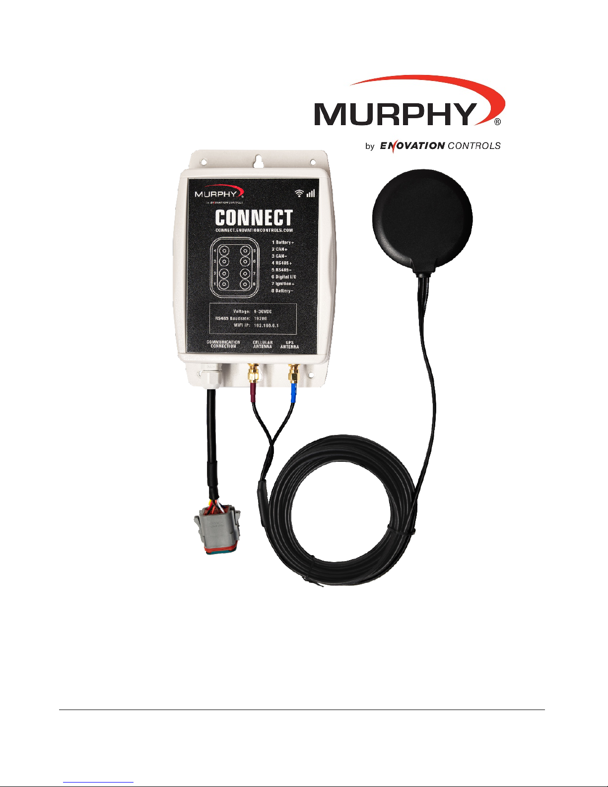
Murphy CONNECT Telemetry Module – P/N 40-70-0525 includes:
• CONNECT Module
• Dual Antenna with GPS and Cellular, 3 meter (9.84ft) length
• Quick Start Guide
Installation
Preparation
Determine the location of where the CONNECT module will be installed. Ensure there is
proper room for the module to be mounted and the harnessing to be properly connected.
Ensure the supplied antenna is mounted in a location exterior to an enclosed area where
cellular and GPS signals are readily accessible to the antenna.
Dimensional drawings are not sized to print and appropriate measurement instruments should
be used when designing and mounting the Murphy CONNECT hardware.
Section 40 5 00-02-1150
2018-10-08
Page 6

Dimensions for Installation
Murphy CONNECT Module
Inches
[mm]
Section 40 6 00-02-1150
2018-10-08
Page 7

Dimensions for Installation
Antenna
Inches
[mm]
Section 40 7 00-02-1150
2018-10-08
Page 8

PIN
8 Pin
1
Battery (+)
2
CAN +
3
CAN -
4
RS485 +
5
RS485 -
6
Digital I/O
7
Ignition +
8
Battery -
Wiring Instructions
PIN Specifications for 8 Position Amphenol Connection
Wiring of this device must meet all applicable electrical codes.
When the accessory harness is used, the PowerCore controller in the panel will need the I/O
established prior to use:
• TEC-10 and ML1000: Set the Digital Output 2 function to Ignition On
(On in Standby).
• ML2000: Set the Digital Output 4 function to Ignition On
(On in Standby).
NOTE: If the application is left in Auto mode, a battery maintaining system should
be installed for possible battery drain due to parasitic loads of ancillary devices
on the system.
Section 40 8 00-02-1150
2018-10-08
Page 9

Troubleshooting
Murphy CONNECT has Wi-Fi communications which allows for minor troubleshooting of the
module. This section details the how to log on and interpret the data.
To access the Wi-Fi for troubleshooting ensure the device has the appropriate power to the
unit. When the unit is powered on the unit can be found by searching for a new Wi-Fi
connection on the PC or smart device.
Wi-Fi Address: CONNECT_xxxx (the xxxx represent the last 4 digits of the MAC address of the
device connecting)
Password: Murphy (use Murphy only when required to login)
Once connected to the device Wi-Fi network, open the browser and type in 192.168.6.1 into
the URL address to access the modem’s page (also shown on the CONNECT front label). The
page should resemble the image below and allow one to see the items listed below for
troubleshooting hardware and connectivity.
Application: States whether the application is running or not running. This should be running at
this stage
Version: Version of the CONNECT device
Connection: States whether the device is connected to a cellular network
Serial Number: Provides Serial Number of device. (Used to register device if device is
installed)
IMEI: Provides IMEI of device. (Used to register device if device is installed)
SIM: Provides SIM number.
Cell Signal: Provides range for cellular network. (0-6 = Poor, 7-15 = Okay, 15+ = Good)
GPS: States whether Locked or not locked for GPS positioning.
Satellites: 1-2 will not allow a lock for GPS, 3+ allow locking for GPS location.
Latitude: Once GPS is locked, provides Latitude coordinates for last known location.
Longitude: Once GPS is locked, provides Longitude coordinates for last known location.
Section 40 9 00-02-1150
2018-10-08
Page 10

Part #
Component
40000665
36” CONNECT Harness from PowerCore Panel to CONNECT Module
Accessories
Specifications
Electrical
Operating Voltage: 9-36 VDC, protected against reverse battery polarity
Max Voltage: -40 to +60 VDC
Power Consumption:
12 VDC: Transmitting: 265 mA
Idle: 135 mA
Off: 0.5 mA (Using IGN to turn off)
On: ~ 175 mA Average
24 VDC: Transmitting: 135 mA
Idle: 90 mA
Off: 0.5 mA (Using IGN to turn off)
On: ~ 115 mA Average
Communications
1-CAN: J1939 (future use)
RS485: Modbus RTU
Wi-Fi: 2.4 GHz 802.11 b/g/n (Troubleshooting)
Cellular: (LTE)
GPS: (Location Services)
Connection: CONNECT Connector: Amphenol AT06-08S
Mating Connector: Amphenol AT04-08PA
Deutsch DT04-08PA
Inputs (1):
(1) Digital Inputs: Future Use (Shared with Digital Output)
Outputs (1):
(1) Digital Output: Future Use (Shared with Digital Input)
Environmental
Operating Temperature: -30°C to +80°C (-22°F to 176°F)
Storage Temperature: -30°C to +80°C (-22°F to 176°F)
Protection: IP67
Vibration: Random vibration, 8.17 Grms (5-2000 Hz), in 3 axes (Vibration spec was
met without the use of rubber isolation mounts)
Shock: 25g in 3 axes (shock specification was met without the use of rubber isolation
mounts)
Mechanical
Case Material: Polycarbonate 94V-2
Section 40 10 00-02-1150
2018-10-08
Page 11

 Loading...