

Page 1
Eno Scientific Well Watch 700 Page 1
Page 2

Eno Scientific
PO Box 1586
Hillsborough, NC 27278
USA
www.enoscientific.com
910-778-2660
Copyright Notice
Copyright © 2017 Eno Scientific, Hillsborough, NC 27278, USA.
All rights reserved.
Part number: 700-901
Eno Scientific Well Watch 700 Page 2
Page 3

WELL WATCH 700
USER MANUAL
TABLE OF CONTENTS
PRODUCT OVERVIEW...................................................................................4
QUICK START GUIDE....................................................................................5
CAUTIONS........................................................................................................7
BACKGROUND – HOW IT WORKS..............................................................9
INSTALLATION.............................................................................................11
SET UP.............................................................................................................14
LOGGING........................................................................................................23
USB COMMUNICATIONS............................................................................24
ANALOG OUTPUT.........................................................................................25
RS232 COMMUNICATIONS.........................................................................26
REMOTE SERIAL OPERATION OVER RS232...........................................27
INTERPRETATION OF SERIAL DATA.......................................................29
MODBUS COMMUNICATIONS...................................................................30
MAINTENANCE.............................................................................................35
FREQUENTLY ASKED QUESTIONS..........................................................36
Appendix A: UPDATE RATES......................................................................38
Appendix B: BAUD RATES..........................................................................39
SPECIFICATIONS..........................................................................................43
ADDITIONAL NOTES...................................................................................44
WARRANTY AND SERVICE........................................................................45
Eno Scientific Well Watch 700 Page 3
Page 4
PRODUCT OVERVIEW
The Well Watch 700 is a simple to use self-contained acoustic ranging instrument
designed specifically to find the distance through a closed pipe (well casing or
sounding tube as small as 1/2”) from one closed end to the to the other. The Well
Watch works by sending a low frequency sound pulse into the pipe, then measuring
the time it takes for the echo to return from the opposite end, which could be a plug or
water surface. The distance is calculated using the sound speed and the time. The low
frequency sound can follow the pipe around corners and in any direction up/down or
horizontally. It can be used to measure any closed pipe, straight or crooked with a
constant diameter.
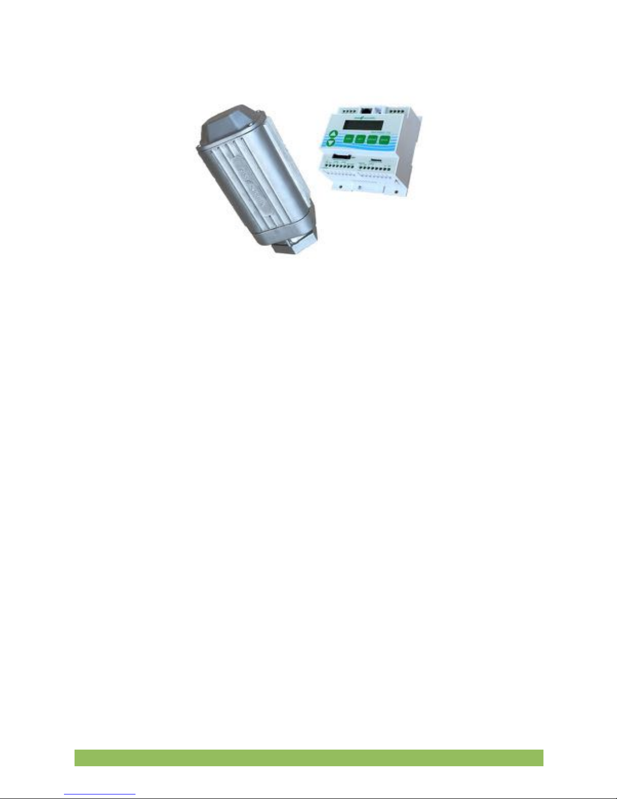
The Well Watch 700 consists of a model 710 control unit and a model 730 smart probe
which are which are interconnected by a 4 conductor cable. The 710 controller
contains the driver electronics, processor, data logger, display, and keypad, while the
smart probe contains a second processor, drive electronics, speaker, a microphone
and a threaded spout to connect to the test pipe.
When the unit powers, it immediately begins sending sound pulses into the well and
attempts to characterize the well. After a few seconds, the depth is calculated and
output for the user. Data can be output in a variety of formats through the several
outputs provided. The controller requires 12-36 vdc external power. The probe is
powered by the controller through the 4 conductor interconnect cable.
Eno Scientific Well Watch 700 Page 4
Page 5

QUICK START GUIDE
The Well Watch is nearly ready to go right out of the box. Follow the few steps below to
find the depth to water. If depth to the water is all you are interested in, then this is all
you need to read. To learn about the more advanced features continue reading the
operation section of this manual.
1.
Mount Probe to Well. Connect the threaded end of the probe to a well
access port. A reducing bushing down to as little as 1/2” can be used if
necessary, however it is better to use as big as possible up to 2”. The probe
is heavy and may require additional support if connected to the well with a
small or flexible tube. The well casing must be closed for the Well Watch to
perform correctly. (See Setup in the manual if this is an issue.)
2.
Mount Controller. Mount the controller in a protected area. It is not weather
proof. It can be mounted using the screw flange or to a DIN rail.
3.
Connect the Controller to the Probe. It is recommended that 1/2” flexible
liquid tight conduit be used between the probe and controller area to prevent
damage and moisture intrusion. However, a moisture tight strain relief may
also be used. Connect the four conductor cable between the probe and 4
probe terminals on the controller matching pin for pin.
4.
Connect Power to the controller. Connect the power source to the Ext Pwr
terminal and adjacent GND terminal. The unit requires 12 to 36 VDC at a
peak load of 150 ma.
5.
Turn meter on. Apply power to turn the meter on. You should see the
display show the product name and hear a popping sound coming from the
probe.
6.
Measure well. After the unit characterizes the well, the measured depth will
Eno Scientific Well Watch 700 Page 5
Page 6

be displayed on the screen. If the measured distance is not as expected,
then proceed to the next step to change the initial settings.
7.
Change initial settings. Press the SET button once to enter the settings
mode. Press the UP or DOWN button to scroll through the available settings.
To change a setting, press ENTER to start the number flashing, press the UP
or DOWN button to change as desired, then press ENTER to enter the new
setting and stop the flashing. Press the UP or DOWN button to continue to
scroll through the other available settings. Press DISP at any time to return to
read the measured depth. For best depth results, the Range Min, Range
Max, and the Well Temperature should all be set.
8. Read
other information. While reading the depth display, press the UP or DOWN
buttons to read other information.
We encourage you to read the frequently asked questions section. They really are
frequently asked. Also, visit our website www.enoscientific.com for the latest manual
and installation tips.
Eno Scientific Well Watch 700 Page 6
Page 7

CAUTIONS
The Well Watch 710 Controller is not water proof!
The controller is designed to be housed in a weather proof shelter. A gasketed
enclosure or well shelter are desired.
Sudden application of well pressure may damage the probe!
The 730 Probe was designed to be used on wells under pressure up to 100 psi.
However, when first connecting the probe to pressure, allow pressure to build slowly (1
psi/second) would be desirable.
External power cannot exceed 36 volts DC!
When supplying external power to the Well Watch, care must be taken to insure that
voltage spikes or induced transients are not conducted into the unit. Over voltage and
surge protectors and proper grounding should be used if this is a possibility.
Use surge suppressors and grounding on signal lines!
When connecting the Well Watch to remote equipment through the RS232 port or
analog outputs, care is required to prevent ground loops, lightning induced transients
etc from reaching the Well Watch. Over voltage and surge protectors and proper
grounding should be used if this is a possibility.
FCC Warning Statement.
THIS DEVICE COMPLIES WITH PART 15 OF THE FCC RULES. OPERATION IS
SUBJECT TO THE FOLLOWING TWO CONDITIONS: (1) THIS DEVICE MAY NOT
CAUSE HARMFUL INTERFERENCE, AND (2) THIS DEVICE MUST ACCEPT ANY
INTERFERENCE RECEIVED, INCLUDING INTERFERENCE THAT MAY CAUSE
UNDESIRED OPERATION.
NOTE: THE GRANTEE IS NOT RESPONSIBLE FOR ANY CHANGES OR
MODIFICATIONS NOT EXPRESSLY APPROVED BY THE PARTY RESPONSIBLE
FOR COMPLIANCE. SUCH MODIFICATIONS COULD VOID THE USER’S
AUTHORITY TO OPERATE THE EQUIPMENT.
Eno Scientific Well Watch 700 Page 7
Page 8

Industry Canada.
This device complies with Industry Canada license-exempt RSS standard(s). Operation
is subject to the following two conditions: (1) this device may not cause interference,
and (2) this device must accept any interference, including interference that may cause
undesired operation of the device.
Le pre !sent appareil est conforme aux CNR d'Industrie Canada applicables aux
appareils radio exempts de licence. L'exploitation est autorise !e aux deux conditions
suivantes : (1) l'appareil ne doit pas produire de brouillage, et (2) l'utilisateur de
l'appareil doit accepter tout brouillage radioe !lectrique subi, me "me si le brouillage est
susceptible d'en compromettre le fonctionnement.
Under Industry Canada regulations, this radio transmitter may only operate using an
antenna of a type and maximum (or lesser) gain approved for the transmitter by
Industry Canada. To reduce potential radio interference to other users, the antenna
type and its gain should be so chosen that the equivalent isotropically radiated power
(e.i.r.p.) is not more than that necessary for successful communication.
Conforme !ment a # la re !glementation d'Industrie Canada, le pre !sent e !metteur radio
peut fonctionner avec une antenne d'un type et d'un gain maximal (ou infe !rieur)
approuve ! pour l'e !metteur par Industrie Canada. Dans le but de re !duire les risques
de brouillage radioe !lectrique a # l'intention des autres utilisateurs, il faut choisir le type
d'antenne et son gain de sorte que la puissance isotrope rayonne !e quivalente (p.i.r.e.)
ne de !passepas l'intensite ! ne !cessaire a # l'e !tablissement d'une communication
satisfaisante.
Eno Scientific Well Watch 700 Page 8
Page 9
BACKGROUND – HOW IT WORKS
The Well Watch 700 works by pushing an air pressure wave or low frequency sound
wave into the well. For this reason, it is important that the probe be connected to a
closed end of the pipe to prevent the air pressure from just escaping the open end.
After the Well Watch sends its sound pulse, it listens for the pulse to return. Since
sound travels at a predictable rate, the Well Watch can calculate where in the well the
pulse was reflected by timing the returning pulse.
The pressure wave generated by the probe will continue to travel into the well until
something disturbs it. Every imperfection in the well will disturb the wave, and every
time it is disturbed, some of the wave changes direction and is reflected back to the
Well Watch leaving the main wave a little weaker. A complete obstruction like the
surface of the water, reflects the entire remaining wave. Most common obstructions like
wires and tubes and pipe couplings do not reflect enough of the wave to cause a
Eno Scientific Well Watch 700 Page 9
Page 10

problem, provided that the remaining part of the main wave is relatively big enough to
be obviously the one of interest.
Some imperfections like a change in casing diameter can cause a significant part of the
wave to be reflected. Where the water may be very far away and its reflected pulse
very weak, the reflection from the imperfection could be the largest wave returning to
the Well Watch. In this case, the Well Watch would lock in on the erroneous reflection
and tell you that the water was at the end of the casing. The Well Watch therefore
offers settings to limit the range in which it will look for reflections. If for example the
casing in your well ended at 40 feet and the water was around 80 feet, then the
minimum range could be set to 60 feet so that the Well Watch would ignore any
reflection from the casing.
The sound wave traveling through the well also loses energy as it travels, more as the
surface of the well casing gets rough or porous. To compensate for this, the Well
Watch increases its gain with time to listen for fainter signals. This can cause problems
if the Well Watch listens for too long. The gain will get so high that the pump noise or
even noise from outside the well will outweigh the desired pulse. Therefore, the
maximum range setting is available to tell the Well Watch how long to listen. If for
example the pump is mounted at 200 feet, then there is no reason to set any more than
250 ft as a maximum range.
The strength of the sound pulse generated by the probe depends on how much space
it needs to fill. A 12” pipe is 4 times larger than a 6” pipe in volume and therefore the
pulse will be 4 times smaller. A weaker pulse becomes more susceptible to pump noise
and loss with depth. While the Well Watch is being used in wells up to 30”, many of
these installations do not get reliable results with running pumps etc. These wells
usually require a sounding tube installed in the well which reaches into the water and
provides a tight connection to the probe at the top. A 3/4” or 1” tube is adequate.
Something to keep in mind, especially for shallow wells, is that the sound wave
bounces off the top and bottom of the well. So it is possible for the pulse to bounce
back and forth many times. In a well where the water level is at 6 feet, the Well Watch
would hear a reflection at 6 feet, then again at 12 feet, then 18 etc, until the pulse gets
weak enough to ignore. In this example, you would be able to see the multiple
reflections by increasing the min range. When set to 9ft, the depth would read 12.
When set to 14ft, it would read 18 etc. In this case, it may be helpful to leave a small
leak at the probe to help dissipate the pulse.
Eno Scientific Well Watch 700 Page 10
Page 11

INSTALLATION
1.
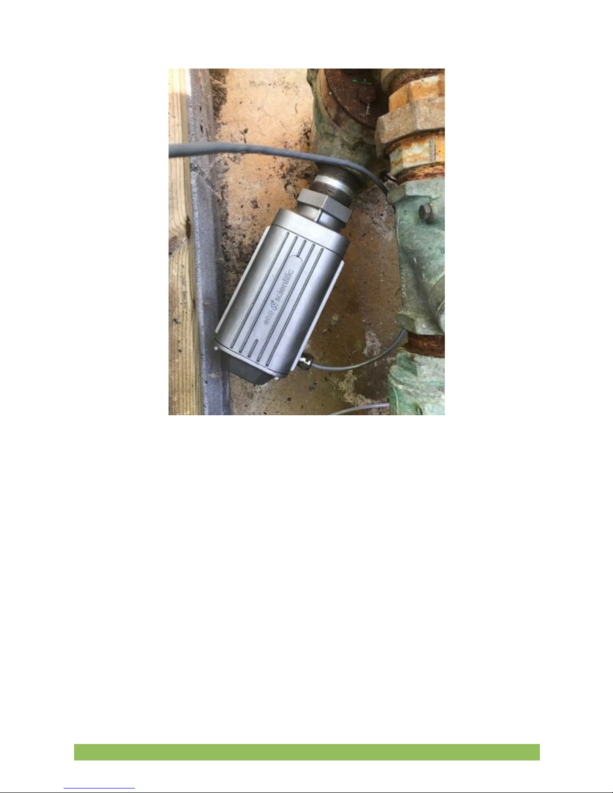
Mount Probe to Well. Connect the threaded end of the probe to a well
access port. A reducing bushing down to as little as 1/2” can be used if
necessary, however it is better to use as big as possible up to 2”. The well
watch pushes air pressure waves
into the well. It is therefore
important that the connection to
the well and top of the well be
closed to air to prevent the air
pressure from escaping and for the
Well Watch to perform correctly. It
is best to install the probe mostly
vertical with the wire connection
toward the lower side to prevent
any water leakage past a poor
seal. Also keep in mind that the
probe is heavy and may require
additional support if connected to
the well with a small or flexible
tube.
2.
Mount Controller. Mount the
controller in a protected area.
It is not weather proof and will
suffer damage if exposed to
the elements. It can be
mounted in any orientation
using the screw flange or to a
DIN rail where access to the
keypad and visibility of the
display can be achieved.
Eno Scientific Well Watch 700 Page 11
Page 12
3.
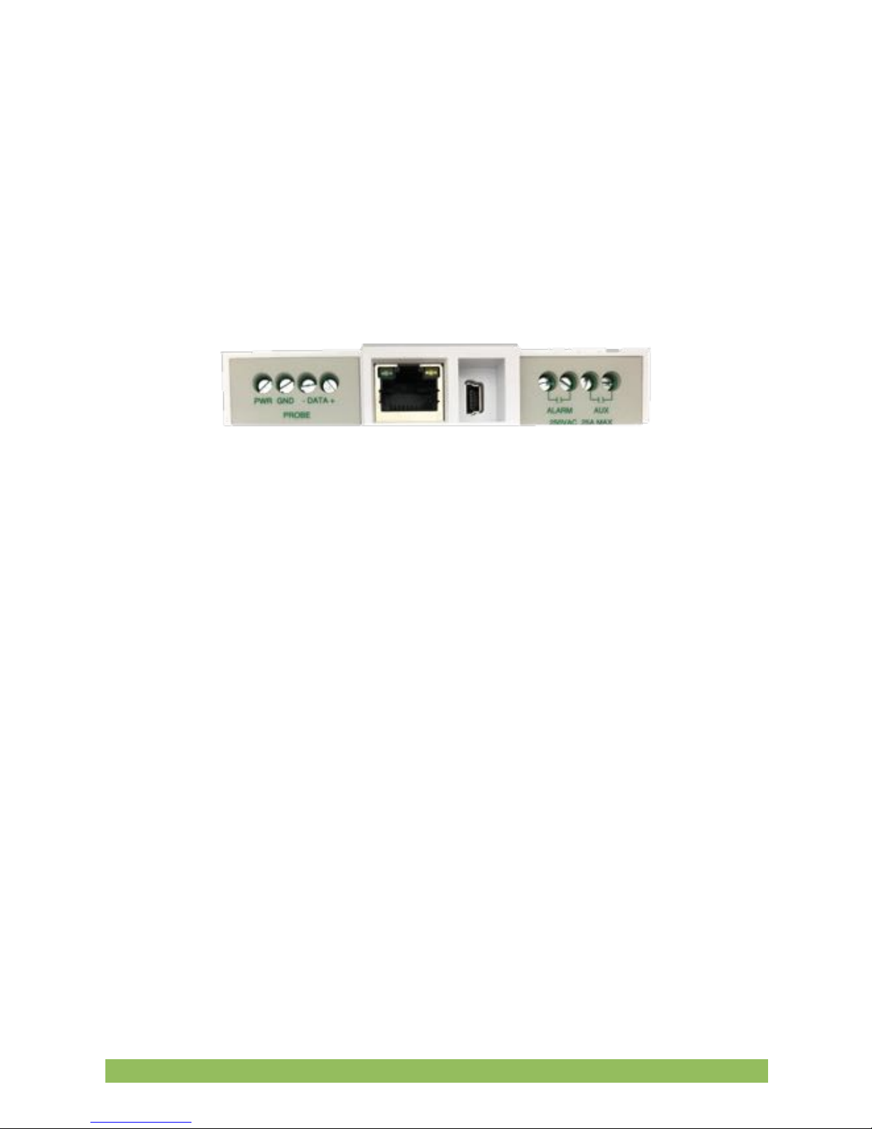
Connect the Controller to the Probe. Four wires are required to connect
the probe to the controller. Any gauge wire from #18 to #28 can be used. A 4
conductor direct bury cable is usually adequate, or if conduit is used ethernet
wire is sufficient. 1/2” flexible liquid tight conduit is recommended between
the probe and controller area to prevent damage and moisture intrusion.
However, a moisture tight strain relief with the direct bury cable may also be
used. Connect the four conductor cable between the probe and 4 probe
terminals on the controller matching pin for pin.
4.
Connect Power to the controller. Connect the power source to the Ext Pwr
terminal and adjacent GND terminal. The unit requires 12 to 36 VDC at a
peak load of 150 ma. GND on the controller refers to the signal ground and
power supply negative, not earth ground.
5.
Connect Outputs from the controller. The controller offers several options
for data and control outputs.
There are two independently programmable relay outputs which have a UL
rating for 30 VDC, 2 A (resistive), or 110 VDC, 0.3 A (resistive) , or 125 VAC,
0.5 A (resistive). These outputs can be used for a remote alarm or control
signal to a pump controller. The outputs are not sufficient to run a pump or
possibly a contactor directly.
Eno Scientific Well Watch 700 Page 12
Page 13
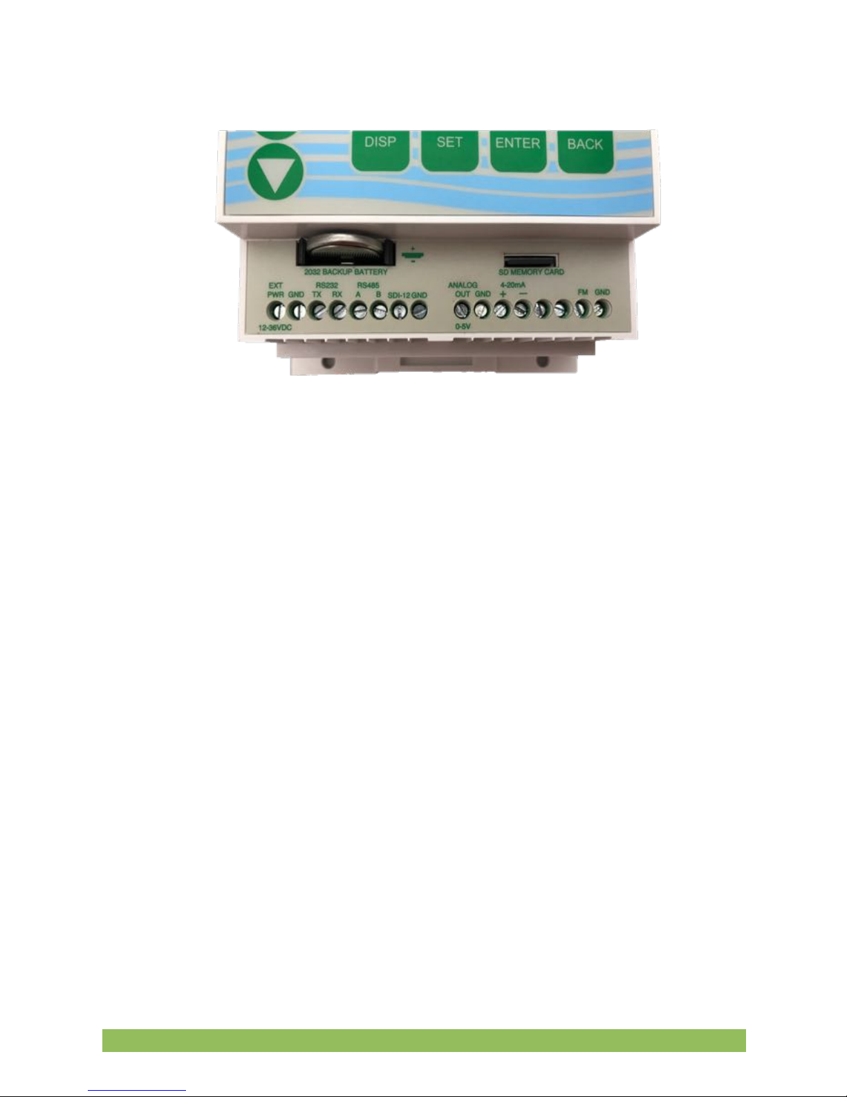
There are 3 available serial output options of which one can be software
selected at a time. RS232, RS485 Modbus, and SDI-12.
RS232 – 3 wires are required to connect the RS232 port to another device
such as a PC with a 9 pin D connector. The TX terminal on the well watch
connects to pin 2 of the D connector, RX to pin 3, and GND to pin 5.
RS485 - 3 wires are required to connect the RS485 port to a Modbus bus.
The A line, the B line, and the shield to the GND terminal.
SDI-12 - 2 wires are required to connect the SDI-12 port to an SDI-12 bus,
the SDI-12 line, and the shield to the GND terminal.
There are 2 analog outputs, 0-5V and 4-20mA. These outputs are available
concurrently and are independently programmable. The 0-5V output can
source up to 15mA and requires and requires one wire for the output as well
as a ground wire or common ground with the destination device.
The 4-20mA output acts as a throttle valve for an applied voltage and is
isolated so that the device power can be used to power the current loop. In
this case a jumper from the ext pwr terminal to 4-20mA+ will power the loop,
and 4-20mA- will act as a source for output current to the target device. This
also requires either a ground wire or common ground with the target device.
Eno Scientific Well Watch 700 Page 13
Page 14

Last is the input for a pulsed flow meter. This input requires a signal wire and
a ground wire. The input is designed to accept an input from a flow meter
that provides either a switch closure or a TTL level pulse.
6.
Turn meter on. Apply power to turn the meter on. You should see the
display show the product name and hear a popping sound coming from the
probe. The Well Watch is now ready to run.
SET UP
POWER ON: Apply power to start the Well Watch. The probe will pulsate and the
LCD screen will display a product information screen for a few seconds then go to the
default DISPLAY mode screen. The depth is displayed on the top line once the unit
adjusts to the well and calculates a stable reading. While the unit adjusts to the well the
display will read “DEPTH SEARCHING.”
Eno Scientific Well Watch 700 Page 14
Page 15

Note: If error conditions exist, line two of the display will be replaced by an alternating
error message. See the ERROR CODES section for details.
The Well Watch has two different operating modes, DISPLAY mode and SET modes.
The DISPLAY modes are accessed by pressing the DISP button, then the UP and
DOWN keys cycle through the available display options. The SET modes are accessed
by pressing the SET button, then the UP and DOWN keys cycle through the available
setting options. When a parameter is shown, pressing the ENT key causes it to flash,
during which time the UP and DOWN keys change the parameter. Press ENT again or
BACK to stop the flashing and return to scrolling through the setting options.
*The DISP key will always return the display to the first display option and the SET key
will always return to the first setting option.
**If left on a set screen, the system will return to the first display screen automatically
after 30 seconds of inactivity.
DISPLAY MODES: There are several DISPLAY options as follow:
1 – DEFAULT display screen which shows current water level with the
time/date on the second line. Once the signal is locked and stable, the depth is
displayed in the units selected. Occasionally a spurious depth reading will be
calculated due to random noise in the well. Software in the Well Watch identifies the
anomaly and holds the last good data through a few bad data points while a good
depth is obtained. An asterisk is displayed before the depth while holding. If a stable
depth is not found in several tries, the depth is replaced with “searching” until one can
be found. If there are any error conditions, such as when the probe is not on the well,
or when the external power supply is low, an error message will alternately be
displayed on the second line.
2 – Flow Meter display screen if the flow meter is enabled, shows the current
flow rate with the totalized flow on the second line. Pressing ENT while on this screen
will reset the flow total to 0.
3 – WIW display screen which shows the total reserve of water in the well
with the rate of change on the second line. The WIW (water-in-well) is calculated using
the set well diameter and the set depth of well. These settings are only used for this
calculation. If the well depth is set to the level of the pump, the WIW number will be the
number of usable gallons (liters) of water in the well.
4 – TIME AND DATA display screen which shows the system time and date.
Pressing ENT while on this screen allows the time and date to be set. Each time ENT
Eno Scientific Well Watch 700 Page 15
Page 16

is pressed, the next number will flash, showing which number is to be changed. Press
BACK or DISP any time to return to normal operation.
SET MODES: Press the SET button at any time to select the first SET option then
UP or DOWN to show the available settings. While viewing a SET screen, press the
ENT key to select the value for change and cause it to flash. While the value flashes,
press the UP or DOWN button to change the value. Rapid scrolling is activated by
holding the up or down button for about a second. Scrolling gets faster and faster while
the button is held down. The button can be released briefly then repressed to resume
change at the high speed. If the button is released, the scroll rate will be decreased at
the same rate that it increased. When the value is as desired, press the ENT or BACK
button to allow scrolling to the other settings or press the DISP button to return to
normal operation. The new settings are saved automatically as they are changed so
there is no need to press ENTER.
There are several setting options as follow:
CONTROLLER PRODUCT INFO – displays the controller product type, configuration
and the software version number. The unit serial number is displayed by pressing the
ENT button. Press ENT or BACK to return to scroll settings.
PROBE PRODUCT INFO – displays the probe product type, configuration and the
software version number. The unit serial number is displayed by pressing the ENT
button. These numbers will all be zero if the controller is not communicating with the
probe. Press ENT or BACK to return to scroll settings.
UNIT ID – sets a user selectable ID number in the range 0-255 to identify the source of
logged data. The default is 0.
PROBE ENABLE – if advance scheduling is enabled allows the user to disable the
probe and use for example, the flow meter only. The default is ENABLED.
UPDATE RATE – selects the time interval for sounding by the probe. Setting to 0
causes continuous sounding. The default is 0.
Eno Scientific Well Watch 700 Page 16
Page 17
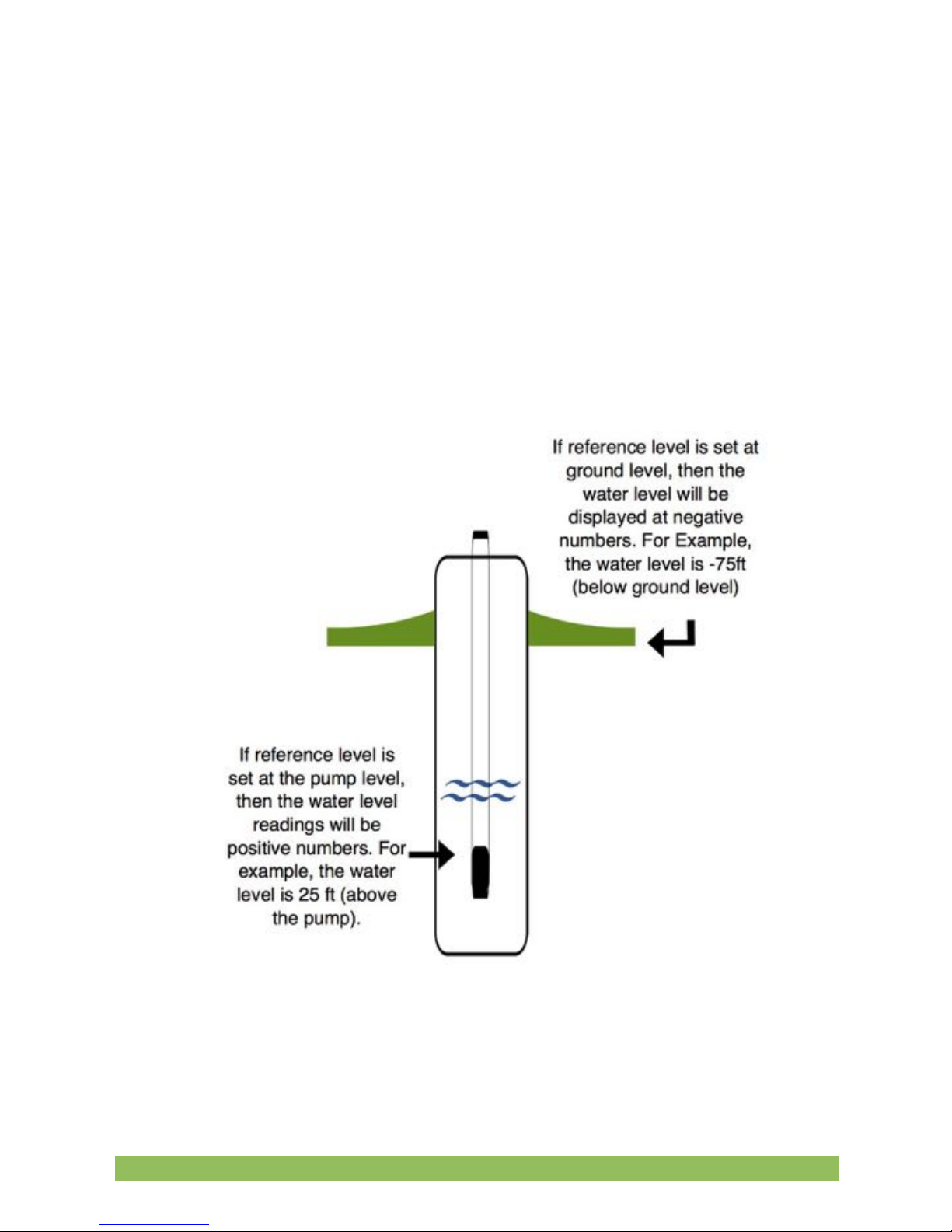
REFERENCE LEVEL – THIS IS IMPORTANT! All depth measurements by the Well
Watch will be displayed with reference to this reference level. Positive numbers are
higher than the reference level into the sky, and negative numbers are below the
reference level into the earth. The default reference level is 0, meaning that all reported
depths are from the Well Watch. It is common to set the reference level to the level of
the pump (for example -550ft), so that numbers will be positive feet (meters) above the
pump. When this number is changed all other settings and readouts will be changed
accordingly.
Eno Scientific Well Watch 700 Page 17
Page 18

LEVEL MAX – sets the highest level ( with respect to the reference level) at which the
Well Watch will start looking for the surface of the water. This is used where there may
be a known defect in the well such as a step down in bore diameter. This kind of defect
will reflect some of the pulse which could compete with the desired reflection from the
water surface. If for example this transition occurred at 42 feet, then set the range min
to 50 feet or more to ignore this erroneous reflection.
LEVEL MIN– sets the lowest level (with respect to the reference level) at which the
Well Watch will continue to look for the surface of the water. A shorter range means
more frequent pulses and faster updates. A longer range gives less frequent updates
and increases the possibility of collection spurious noise. This should be set just
beyond the lowest level expected.
WELL TEMP – sets the average air temperature in the well. If you do not know the well
temperature, reference the Water Temperature chart below. It is also usually very close
to the water temperature. This temperature is used to calculate the sound speed and in
turn, the distance. The distance error is fairly small for variations in temperature, about
1% (1 ft per 100 ft) for a 10 ºF (5.6 ºC) temperature error.
Eno Scientific Well Watch 700 Page 18
Page 19

METHANE – sets the concentration of methane mixed with the air in the well. Sound
travels through methane much faster than through air. The concentration set here is
used to calculate the sound speed and correct for this error. The Well Watch does not
measure methane but can be used to estimate the concentration if a reference
measurement is taken using another method like a tape, then changing the methane
so that the two methods match.
SOUND TUBE – sets the diameter of a tube used to carry the sound pulse to the
water. Small diameter (less than 2”) tend to reduce the sound speed. At 1/2” diameter it
is approximately 2% less, which results in approximately 2' per 100'. This setting
corrects for this error.
WELL DIAMETER – sets the diameter of the well casing. This setting is used
exclusively to calculate the amount of water in the well. It does not effect the
measurement.
WELL DEPTH – sets the depth of the well. This setting is used exclusively to calculate
the amount of water in the well. It does not effect the measurement. This is usually set
to the level of the pump so that the WIW display indicates the amount of useable water
in the well.
FLOW METER – enables the flow meter functions in software if the flow meter input is
being used. Press ENT to enable the flow meter. Press enter again to set the scale
factor for the flow meter in gal/pulse (liters/pulse). Press ENT again or BACK to return
to setting scroll mode.
LOGGING – enables the logging features of the Well Watch. When logging is enabled,
The Well Watch schedules the next periodic log point to align with the system clock so
all log periods will result with a point on the hour. When the next scheduled time
arrives, a message is displayed on the error line and remains until valid data is
recorded. Logged data is stored in the SD memory card and is appended to a data file
named WSLOGxxx.txt, where xxx is the 3 digit well ID set earlier.
**LOG RATE – sets the time interval in minutes between logged data points. This
setting is available if logging is ENABLED. Every measurement is recorded if it is set to
zero.
Eno Scientific Well Watch 700 Page 19
Page 20

SERIAL COMM – selects the type of serial communications to be used. Even though
there are 3 sets of serial communications terminals on the controller, only one can be
used at a time. Press ENT to select RS232, RS485 Modbus, SDI-12 or none.
RS232 DATA – enables the transmission of current data over the RS232 connection.
This feature is used when the Well Watch is used with a remote readout or data
transmission system such as SCADA or a PC. Press the ENT to change the setting,
then UP or DOWN button to select: Off, Continuous, Depth only. When set to
Continuous, a data line for every measurement is sent over the serial port
automatically. Transmitted data includes all measured data, as well as the error code.
When Depth Only is selected, only the depth is included in the data. Select Off to
disable automatic data transmission, but retain the ability to program the unit remotely
or request data. (See the section on serial communication for details)
RS232 UPDATE – if advanced scheduling is enabled allows reporting of serial data to
be scheduled independently of the system update time.
RS232 SETUP – if RS232 is selected, sets the serial port parameters. The default is
19,200 baud, 8 data bits, 1 stop bit, and no parity. Press ENT to cycle through the
various parameters. Then ENT again or BACK to return to settings scroll mode.
RS485 MODBUS DATA – if RS485 is selected, sets MODBUS parameters for
transmission of data over the RS485 connection. Two modes are available: RTU
(default) or ASCII.
RS485 SETUP – if RS485 is selected, sets the serial port parameters for RS485
communications. The default is 9,600 baud, 8 data bits, 1 stop bit, and no parity. Press
ENT to cycle through the various parameters. Then ENT again or BACK to return to
settings scroll mode.
MODBUS ADDRESS – if RS485 is selected, sets the MODBUS address. This is the
address which will identify the Well Watch on the Modbus bus, which can be any
unused address on the bus from 1 to 247.
ANALOG DEPTH @0V – sets the range for both the 0-5V and the 4-20mA analog
outputs. This setting sets the depth with respect to the reference level at which the
outputs will be 0V and 4mA.
Eno Scientific Well Watch 700 Page 20
Page 21

ANALOG DEPTH @5V – sets the range for both the 0-5V and the 4-20mA analog
outputs. This setting sets the depth with respect to the reference level at which the
outputs will be 5V and 20mA.
ALARM OUTPUT– enables the alarm output relay. The output contacts are normally
open, activating the alarm closes the contacts. The alarm relay can be configured as
one of the following options:
None to keep the contacts open,
Low to close the contacts when the water level reaches the low set point,
High to close the contacts when the water level reaches a hi set point.
Both to close the contacts when the water level above the high and below
the low set points,
Test to allow the operator to manually operate the relay contacts by pressing
the ENT key. Press BACK to resume set scrolling.
ALARM HIGH ON – available if the high alarm is enabled, sets the high level with
respect to the reference level at which the alarm contacts will close. So for example, if
Alarm High is selected and the high set point is set to -150, then the alarm contacts will
close when the level rises above -150 ft and open otherwise.
ALARM LOW ON – available if the low alarm is enabled, sets the low (deep) level with
respect to the reference level at which the alarm contacts will close. So for example, if
Alarm LOW is selected and the low set point is set to -650, then the alarm contacts will
close when the level drops below -650 ft and open otherwise.
AUX OUTPUT– enables the auxiliary output relay. The output contacts are normally
open, activating the aux output closes the contacts. The aux relay output works
differently than the alarm output. The aux relay contacts close if the water level rises
above the high set point and opens when the level drops below the low set point. This
would be appropriate for controlling a pump to maintain a water level. The aux output
can be configured as one of the following options:
None to keep the contacts open,
Enabled,
Test to allow the operator to manually operate the relay contacts by pressing
the ENT key. Press BACK to resume set scrolling.
AUX OFF LEVEL – available if the aux output is enabled, sets the low (deep) level with
respect to the reference level at which the aux contacts will open. So for example, if the
Eno Scientific Well Watch 700 Page 21
Page 22

Aux low set point is set to -650, then the aux contacts will open when the level drops
below -650 ft.
AUX ON LEVEL – available if the aux output is enabled, sets the high level with
respect to the reference level at which the aux contacts will close. So for example, if
Aux High set point is set to -150, then the aux contacts will close when the level rises
above -150 ft.
UNITS – selects the measurement system for the data. The following options are
available:
English for decimal feet, degrees Fahrenheit and gallons;
English ft-in for distance displayed as feet and inches;
Metric for meters, degrees Celsius, and liters, or
Imperial for feet, degrees Fahrenheit and imperial gallons.
CONTRAST - sets the contrast level on the LCD screen from 0 (brightest) to 20
(dimmest).
SAVE SETTINGS – settings changed on the set screens will remain until the power is
turned off, unless they are saved. Press ENTER on this screen to make the current
settings the power on defaults.
FACTORY RESET – allows the user return the unit to the factory default configuration.
Press the ENT button to make the selection. All user settings will be set to the Factory
default values.
DIAGNOSTICS – allows the user to display and perform some diagnostic functions.
The diagnostic display screens are as follow:
Last update – showing D for the last reported depth without filtering, BC for
the number of bad readings since a good one, F is the strength of the out going pulse,
E is the strength of the returning pulse, N is the level of background noise. The signal
strength numbers refer to the amplifier gain where 150 represents a strong signal and
300 is very weak.
Probe Codes – show 32 bits of information, each screen segment
represents a bit and will be a '.' if normal or a letter if the condition exists. These are not
all error codes but also represent for example signals within certain strength bands.
(see the section on error codes for an explanation)
Probe Status – show 20 bits of information, each screen segment
represents a bit and will be a '.' if normal or a letter if the condition exists. These are not
Eno Scientific Well Watch 700 Page 22
Page 23

all error codes but also represent for example signals within certain strength bands.
(see the section on error codes for an explanation)
Regression coefficients – show the intercept, slope and error signal for the
short and long regressions.
Error codes – press ENT to scroll through the current controller internal error
codes (for factory diagnostics).
Log Raw Data – allows the user to record internal diagnostics with raw data
from the well for factory analysis. This data file is recorded to the SD memory card with
the name: WSRAWxxx.txt, where xxx is a sequential number assigned automatically.
Press ENT to initiate, then watch the % complete bar scroll to completion. This should
be done at least 3 times in problem situations and emailed to Eno Scientific for
analysis.
Autocal – allows the user to initiate the autocalibration feature. Press ENT to
start. The Well Watch will generate a series of pulses to characterize the well, then set
the internal pulse parameters to optimize the response. This is done automatically if
the Well Watch has difficulty getting reliable readings.
LOGGING
The Well Watch 710 controller includes a built-in data logger which can record the
measurement data automatically at preset intervals when automatic logging is enabled.
Each data point includes the system time and date, well ID, depth, temperature, battery
voltage, signal strength, and error codes. The data is recorded in the SD memory
which maintains the data even if the battery goes dead. This memory is only accessible
using the USB interface as described in the next section or by removing the SD card
and using an external reader.
To automatically log data on a schedule, press the SET button then scroll to the
logging screen. Press ENT to select the option for change, then the UP or DOWN
button until the second display line reads ENABLED. Press the ENT button again or
BACK to return to the setting scroll mode. When enabled every time the Well Watch
takes a new reading, it will be recorded in the log. If advanced scheduling is enabled,
press UP to show the log period screen. Press the UP button to set the log interval in
minutes. If the log period is set to 2 minutes, the Well Watch will initiate a log sequence
every two minutes. The time between logged data may vary by a few seconds
depending on how long it takes to get a stable reading. If the log period is set to zero
minutes, then every reading is logged. Logging intervals are available from every
reading up to every 24 hours. (For available rates, see Appendix A)
Eno Scientific Well Watch 700 Page 23
Page 24

The log data files are simple ascii text files which can be opened with any common
program such as Notepad, MS Word or Excel. The data files created are named
WSLOGxxx.TXT where xxx is the well ID in the form 001 etc. Each data point stored is
appended to the file corresponding to the currently set well ID. If a file does not exist for
the well ID selected, it is created. Once the data is copied to the computer, the file can
be deleted from the Well Watch. A new file will be created automatically if the same ID
is used.
The log data is formatted as follows:
2018/04/20 18:26:02 D-566.23 T 88.5/81.8 B23.5/11.4/11.2 G171/199/300 N001 R0005/F04000
2018/04/20 18:26:04 D-566.23 T 88.5/81.8 B23.5/11.5/11.2 G171/199/300 N002 R0001/F04000
2018/04/20 18:26:06 D-566.12 T 88.5/81.6 B23.5/11.4/11.2 G171/199/240 N002 R0001/F24000
2018/04/20 18:26:07 D-566.01 T 88.5/81.4 B23.5/11.4/11.2 G171/199/300 N002 R0001/F24000
The interpretation of this data is as follows:
Data – year/month/day
Time – hour:min:sec
Depth – in feet (meters) with respect to the reference level
Temperature – controller temp/probe temp
Battery Voltage – controller ext pwr/probe cap before pulse/probe cap after
pulse
Gain – outgoing pulse/return pulse/noise
Noise level – index
Error codes – (see appendix)
USB COMMUNICATIONS
The Well Watch 710 contains an expanded memory which provides enough memory to
record one data point per minute for over 50 years. This memory supports a windows
compatible file system which can be accessed using the USB port. When the Well
Watch is connected to a computer with a USB cable, the computer will identify the Well
Watch as a mass storage device and show the available log files in an explorer window
which can be copied directly to a directory on the computer and deleted from the Well
Watch. Other Well Watch functions are disabled while accessing the SD card through
the USB port.
Eno Scientific Well Watch 700 Page 24
Page 25
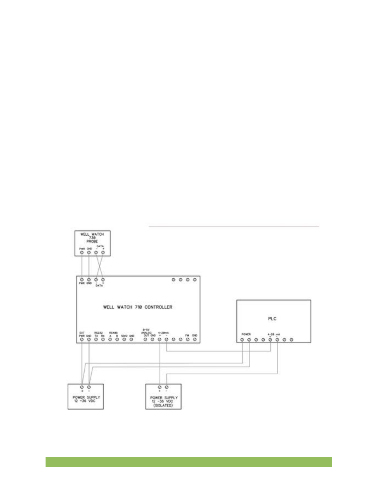
ANALOG OUTPUT
The Well Watch comes standard with 0-5 volt and 4-20 ma analog outputs. They are
both driven by a common source so that when the output voltage is 0v, the output
current is 4 ma, and when the output voltage is 5v the current is 20ma. The output
range is set by the user by selecting the Analog depth @0v and the Analog depth @5v.
The voltage will then vary monotonically over this range and may be increasing or
decreasing.
The 0-5 volt output can supply a maximum of 15ma.
The 4-20 ma output is an isolated current regulator for a supply voltage up to 36 v
supplied externally. The Well Watch external power can be jumped to the +4-20
terminal to allow the -4-20 terminal to source 4-20mA. This can be done provided the
destination device uses a common ground.
Eno Scientific Well Watch 700 Page 25
Page 26

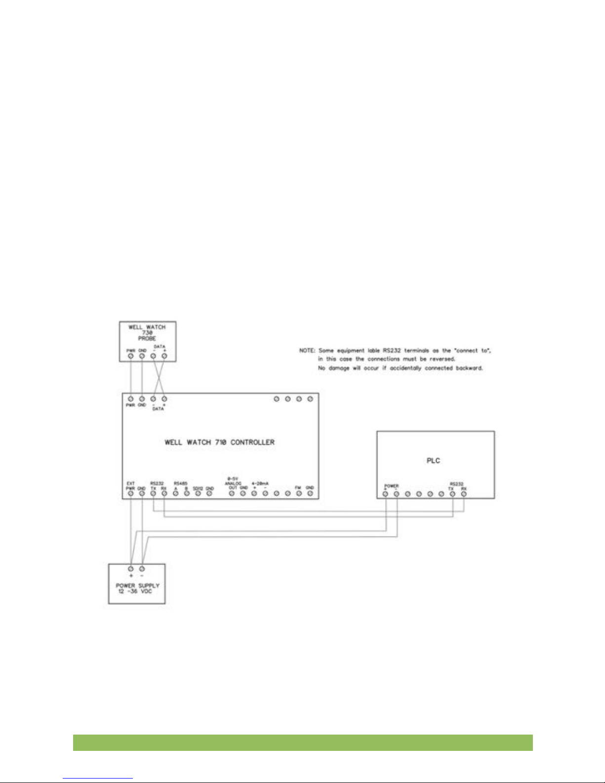
RS232 COMMUNICATIONS
The Well Watch offers a standard serial communications port for connection to a
computer or remote device such as a SCADA system or remote readout. To connect to
a standard device such as a PC with a standard 9 pin D connector, only 3 wires are
necessary. The TX terminal on the well watch goes to pin 2 on the D connector, RX
goes to pin 3 and GND goes to pin 5. A simple serial to USB adapter is available from
Eno Scientific or most computer stores to use with laptops without serial ports. The
default serial configuration on the Well Watch is 19200 baud, 8 data bits, 1 stop bit, no
parity, and no flow control. These settings can be changed from the set screen on the
keypad.
The serial port is bi-directional and allows communication from the Well Watch to the
remote device and back. This allows the Well Watch to be programmed and operated
from a remote location. The Well Watch offers a complete command set over the serial
link to allow configuring the Well Watch settings. A standard terminal emulator
program such as HyperTerminal (included with windows) or Tera Term Pro (available
for free download from http://www.logmett.com) can be used from a computer to
operate the Well Watch remotely (see the section on remote operation).
The Well Watch can also be instructed to automatically transmit new data over the
serial port as it is generated. To activate this feature from the keypad, select RS232 on
the serial comm screen, then select continuous or depth only on the RS232 screen.
When set to continuous, the complete data set is transmitted with each pulse. When
set to depth only, only the depth is transmitted.
Eno Scientific Well Watch 700 Page 26
Page 27
REMOTE SERIAL OPERATION OVER RS232
When the Well Watch is connected to a computer or other bi-directional remote
device, the Well Watch can be controlled and configured using a set of simple
commands.
If using a terminal emulator on the computer, establish a connection with the Well
Watch by selecting the COM port connected to the Well Watch. If your computer has a
built-in com port, it will probably be COM1. If you are using a USB adapter it may be
any where from COM3 thru COM12. Then enter the port settings: 19200 baud, 8 data
bits, parity none, 1 stop bit, and flow control none. Turn on the Well Watch and press
the <return> key on your computer. If it is set up correctly, the Well Watch will return
with a line of data and a WS2k> prompt on the screen. If the Well Watch does not
respond, select a different COM port and try again.
Eno Scientific Well Watch 700 Page 27
Page 28

Once the connection has been established, commands can be send from the computer
to the Well Watch. The remote commands are case sensitive and must be entered
exactly as shown on the list below. One command per line, terminated by a <return>.
Extra tabs or spaces will not be accepted.
Examples:
Press "rn30<return>" to set the min range to 30 feet.
Press "u0<return>" to set english units mode or "u2<return>" to set metric.
If serial output is enabled, the prompt and input may be written over on the screen but
the input will still be interpreted correctly. It may be easier to disable the serial output
while using remote commands. Press “cs0<return>” to turn off serial reporting and
“cs1<return>” to turn in back on when finished.
USER REMOTE COMMANDS - In the following list, [iiii] indicates a parameter of up to
a 4 character integer (no decimal point), [ddddd] indicates up to 5 character decimal
number (decimal point optional), [cc] indicates two nonnumeric characters, and <ret>
indicates a return.
<ret> send current data
a0<ret> alarm off
a1<ret> low alarm on
a2<ret> high alarm on
a3<ret> both alarms on
ah[iiii] <ret> set high alarm level
al[iiii] <ret> set low alarm level
s0<ret> turn off serial communications
s1<ret> turn on RS232
s2<ret> turn on RS485 MODBUS
s3<ret> turn on SDI-12
sd0<ret> turn off automatic RS232 data output
sd1<ret> turn on automatic RS232 data output
sd2<ret> turn on automatic RS232 depth only output
su[ii] set the data update rate index
h<ret> display command list
i[iii]<ret> set unit ID
l0<ret> logging off
l1<ret> logging on
lu[iiii] <ret> logging update period index
Eno Scientific Well Watch 700 Page 28
Page 29

m0<ret> puts unit in normal operation mode
m1<ret> puts unit in set mode
nh[ddddd] <ret> set depth at which the analog output is 0volts.
nl[ddddd] <ret> set depth at which the analog output is 5volts.
p0<ret> probe off
p1<ret> probe on
pu[iiii] <ret> probe update period index
rh[ddddd] <ret> set maximum measurement level
rl[ddddd] <ret> set minimum measurement level
ro[ddddd] <ret> set reference level
tm[hh:mm:ss] <ret> set time
td[yy/mm/dd] <ret> set date
u0<ret> set english units (ft)
u1<ret> set english units (ft in)
u2<ret> set metric units
wd[ddddd] <ret> set well depth
wi[ddddd] <ret> set well diameter
ws[ddddd] <ret> set sound tube diameter
wt[ddddd] <ret> set well temperature
wm[ddddd] <ret> set well methane concentration
x0<ret> disable the aux output
x1<ret> enable the aux output
xh[ddddd] set the turn off level for the aux output
xl[ddddd] set the turn on level for the aux output
?<return> send a list of the current settings
INTERPRETATION OF SERIAL DATA
DATA QUERY - A simple <return> sent to the unit instructs the unit to send the current
data set. Each data element is preceded by an upper case letter for the identity of the
following number. A typical data line is as follow: data, time, D depth, other data, B
battery voltage and the R error code. (see the error code section for codes).
Example:
WW660 >
>> #000 D 74.45 T 76.4 B 5.97 R 0002
WW660 >
Eno Scientific Well Watch 700 Page 29
Page 30

This indicates that the depth is 74.45 feet, the probe temp is 76.4 F, the battery voltage
is 5.97, and the error code is 2 meaning that the battery voltage is below 6.5 volts.
SYSTEM STATE - A "?" command sent to the unit instructs the unit to send its current
operating state. This will include 3 lines of data. The first line reports the model number
and features, the software version, the unit serial number, and the user set ID number.
The second and third lines report the applicable system settings prefixed by the
commands used to set them as listed in the table in the section on external commands.
Example:
WW660 > ?
Mod #WW710-077303 Ver # 7101-008 Ser #080628015 ID #001
rn 25.0 rx 500.0 w 60.5 u0 a0 al 500.00 ah 25.00
nh 25.00 nl 500.00 cs0681n cm0681n RTU 11 cf0 6
WW710 >
In this example, "rn" indicates that the min range is 25.0, and the well temperature is
set to 60.5 degrees, etc.
MODBUS COMMUNICATIONS
The RS485 port on the Well Watch is configured to communicate as a slave device on
a two wire Modbus bus. When the RS485 Modbus port is enabled, the Well Watch
becomes a Modbus slave device listening for data requests from a Modbus master
device using either RTU or ASCII mode. Data requests with the address set in the Well
Watch will be processed and a data packet containing the requested data will be sent
back to the master.
The Well Watch can be configured for a Modbus network by setting the Serial mode to
RS485. Then select the Modbus mode, either RTU or ASCII. Then set the serial
settings, the baud rate, number of data bits, stop bits and the parity. Scroll the setting
once more to set the MODBUS address for the Well Watch. This can be any number
from 1 to 243 which has not been used by any other device on the network.
Eno Scientific Well Watch 700 Page 30
Page 31
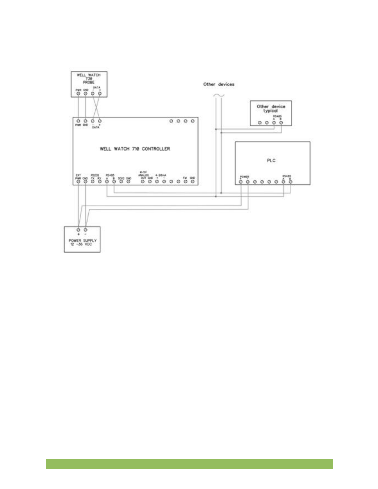
By default, the Well Watch is set to the most typical settings:
9600 baud, 8,1,even
RTU mode
address 011
WS710 Modbus Addressing:
All registers are internally 32 bits wide, accessed through modbus as 16 bit words.
2 registers are required for a complete read or write. Therefore each 32 bit register
is addressed as all even numbers. Address numbers require the addition of 1 to 4
thousand to define the formatting of the data. Addition of 1000 sends data high byte
of the high word first to low byte of the low word last. Addition of 2000 swaps words,
3000 swaps bytes of each word, and 4000 swaps both. So for example if registers 20
and 21 contained A B, and C D respectively, then:
address 1020 would send A B C D
address 2020 would send C D A B
Eno Scientific Well Watch 700 Page 31
Page 32

address 3020 would send B A D C
address 4020 would send D C B A
ADDR ACCESS TYPE DESCRIPTION
------------------------------------------------------ 0 R/O Flo32 depth adjusted for reference level
2 R/O Flo32 depth running average
4 R/O Flo32 last good logged distance
6 R/O Int32U count bad readings since last good dist
8 R/O Int32S quality factor for current reading
10 R/O Flo32 slope of short line fit
12 R/O Flo32 intercept of short line fit
14 R/O Flo32 error from short line fit
16 R/O Flo32 slope of long line fit
18 R/O Flo32 intercept of long line fit
20 R/O Flo32 error from long line fit
22 R/O Flo32 probe bat voltage high
24 R/O Flo32 probe bat voltage low
26 R/O Flo32 probe temperature
28 R/O Flo32 probe reported depth
30 R/O Int32U amp gain fingerprint
32 R/O Int32U amp gain echo
34 R/O Int32U amp gain for max noise
36 R/O Int32U probe noise level as % of signal max
38 R/O Int32U probe error codes
40 R/O Int32U system error code
42 R/O Flo32 controller battery voltage
44 R/O Flo32 controller temperature 1
46 R/O Flo32 flow total
48 R/O Flo32 flow rate from flow meter G/S
50 R/O Flo32 calculated water in well
52 R/O Flo32 calculated rate of change of water in well
54 R/O Int32U system time packed
56 R/O Int32U system date packed
58 R/W Int32U system seconds
60 R/W Int32U system minutes
Eno Scientific Well Watch 700 Page 32
Page 33

62 R/W Int32U system hours
64 R/W Int32U system days
66 R/W Int32U system months
68 R/W Int32U system years
100 R/O Int32U controller type
102 R/O Int32U software version
104 R/O Int32U software build number
106 R/O Int32U build parameters
108 R/O Int32U product features
110 R/O Int32U unit serial number
112 R/W Int32U unit ID
114 R/O Int32U probe type
116 R/O Int32U probe software version
118 R/O Int32U probe software build number
120 R/O Int32U probe build parameters
122 R/O Int32U probe product features
124 R/O Int32U probe unit serial number
126 R/W Int32U probe unit ID
128 R/W Int32U power save mode
130 R/O Int32U enable and next turn on time for probe
132 R/W Int32U english=0; metric=1
134 R/W Flo32 max range (min level)
136 R/W Flo32 min range (max level)
138 R/W Flo32 depth of well
140 R/W Flo32 diameter of well
142 R/W Flo32 reference level
144 R/W Flo32 well temperature
146 R/W Int32U methane concentration %
148 R/W Flo32 sounding tube diameter
150 R/W Int32U type of autocal bit field (see prb_mode_enum)
152 R/O Int32U type of operation bit field (see prb_mode_enum)
154 R/W Int32U pulse type 0,1
156 R/W Flo32 pulse volume -1.00 - +1.00
158 R/W Flo32 not used
160 R/W Int32U pulse duration * .1ms
Eno Scientific Well Watch 700 Page 33
Page 34

162 R/W Int32U not used
164 R/W Int32S lag from spkr to mic * .1ms
166 R/W Flo32 Internal reflection coef -1.00 - +1.00
168 R/W Int32U alarm enable 0-off, 1-low, 2-high, 3-high&low
170 R/W Flo32 high alarm setpoint
172 R/W Flo32 low alarm setpoint
174 R/W Int32U auxout enable 0-off, 1-on
176 R/W Flo32 high auxout setpoint
178 R/W Flo32 low auxout setpoint
180 R/W Flo32 0v analog setpoint
182 R/W Flo32 5v analog setpoint
184 R/W Int32U probe enable
186 R/W Int32U probe interval minutes
188 R/W Int32U logging enable
190 R/W Int32U logging interval minutes
192 R/W Int32U serial enable 0-off, 1-rs232, 2-rs485, 3-sdi12
194 R/W Int32U serial interval minutes
196 R/W Int32U flow meter enable
198 R/W Flo32 scale factor for flow meter
200 R/W Flo32 offset for flow meter
202 R/W Int32U flow accumulator
204 R/W Flo32 battery voltage scale factor
206 R/W Flo32 scale factor for thermistor
208 R/W Flo32 offset for thermistor
210 R/W Int32U zero level for analog output
212 R/W Int32U max level for analog output
214 R/W Int32U packed rs232 config
216 R/W Int32U rs232 mode
218 R/W Int32U rs232 baud rate index (see appendix)
220 R/W Int32U rs232 data bits
222 R/W Int32U rs232 stop bits
224 R/W Int32U rs232 parity enable
226 R/W Int32U rs232 parity
228 R/W Int32U packed rs485 config
230 R/W Int32U rs485 mode
Eno Scientific Well Watch 700 Page 34
Page 35

232 R/W Int32U rs485 baud rate index (see appendix)
234 R/W Int32U rs485 data bits
236 R/W Int32U rs485 stop bits
238 R/W Int32U rs485 parity enable
240 R/W Int32U rs485 parity
242 R/W Int32U modbus address
244 R/W Int32U modbus mode
260 R/W Int32U local ip addr 1
262 R/W Int32U local ip addr 2
264 R/W Int32U local ip addr 3
266 R/W Int32U local ip addr 4
268 R/W Int32U gateway ip addr 1
270 R/W Int32U gateway ip addr 2
272 R/W Int32U gateway ip addr 3
274 R/W Int32U gateway ip addr 4
276 R/W Int32U ip mask 1
278 R/W Int32U ip mask 2
280 R/W Int32U ip mask 3
282 R/W Int32U ip mask 4
284 R/W Int32U mac address 1
286 R/W Int32U mac address 2
288 R/W Int32U mac address 3
290 R/W Int32U mac address 4
292 R/W Int32U mac address 5
294 R/W Int32U mac address 6
MAINTENANCE
LITHIUM BATTERY – There is a lithium coin cell inside the unit to maintain the system
clock and settings. This is a common type 2032 battery available at most local outlets.
This battery typically lasts 2 years or more. If the unit powers up in the set date mode,
this indicates that the battery needs replacing. This battery can be accessed on the
front lower left of the controller and removed with a needle nose pliers. Caution
however that one of the battery surfaces to prevent shorting the power supply.
Eno Scientific Well Watch 700 Page 35
Page 36

FREQUENTLY ASKED QUESTIONS
Q: Can I use the Well Watch on an open well?
A: The Well Watch was designed to work on a closed well. A simple piece of rigid card
board or plastic held tight against the opening is enough to meet this requirement. In
many cases it will work on the open well but may be off by a couple feet.
Q: Does the Well Watch work on wells with the pump installed?
A: Yes. The sound pulse used for measuring is not disturbed by the presence on pump
wiring or piping.
Q: What if there are guard rings or torque arresters on the pump line?
A: The Well Watch will read past most guard rings and torque arresters with little signal
attenuation. Some torque arresters may block more than 90% of the well opening and
may cause problems.
Q: Will the Well Watch work with the pump running?
A: Generally, yes. If however the pump is exceptionally noisy and or the water level is
near or below the pump, it is possible that the noise from the pump could interfere with
the depth measurement.
Q: Does the Well Watch work on larger diameter wells?
A: The Well Watch, with the standard probe, works on wells up to 18” in diameter.
However, as the well diameter increases, the signal strength weakens and becomes
more susceptible to pump noise and imperfections in the well.
Q: How deep will the Well Watch measure?
A: The maximum range is 7000 feet. This may not be achievable on all wells however.
On a good 6” well with tight clean casing all the way down to the water and little or no
obstructions along the way, maximum range can be achieved. On uncased wells drilled
through porous stone or with irregular walls, or any obstructions such as spacer rings
or couplings the range will be reduced.
Q: Does the Well Watch work in wells with perforated casing?
A: If the perforations are exposed (above the water line) and the exterior of the casing
is very porous like crushed stone, then the perforations will dampen the sound pulse
and there will be no reflection for the Well Watch to detect. In this case, the Well Watch
will track the descending water level until it gets to the perforations and then stick at the
start of the exposed perforations as the water level continues to descend.
Eno Scientific Well Watch 700 Page 36
Page 37

Q: Does the Well Watch work in crooked wells?
A: Yes. The sound pulse used to measure the depth will even go around corners and
obstructions which block less than 90% of the well opening.
Q: What if the well contains a constant pressure pump system with the accumulator
tank in the well?
A: The in well accumulators tend to block the well shaft entirely. If this is the case then
the Well Watch will be unable to find the distance to the water past the accumulator.
Q: Can the Well Watch measure past a pit-less adapter?
A: Yes. The common side mount pit-less adapter typically does not block a significant
portion of the well opening and will not interfere with the depth sensing. Some pit-less
adapters, however, are recessed into the well and do block most of the opening. These
installations may be more difficult. There are two ways to handle these cases: The
probe spout can be extended into the well and seated on the access hole through the
pit-less adapter. When this is done, the microphone tube must also be extended to
reach into the well cavity.
Q: Can the Well Watch be used on hand dug wells?
A: Hand dug wells are often fairly large and irregular, and as such may cause
problems for the Well Watch due to multiple or weak reflections. Some work and some
do not. However, in any difficult to measure well, a small tube can be installed
specifically for measurement. A 3/4” PE pipe can be used for up to 1000' provided
splicers do not restrict the ID.
Q: Can I use the Well Watch to measure the water level in a tank?
A: There are three issues here. First, the Well Watch is designed to be used in a
constant diameter pipe. Tank measurement is generally into a large opening which
would create multiple reflections and hence an uncertain reading. Second, the
minimum measurement distance is about 15 feet, so unless the sounder is mounted at
least 15 feet from the maximum water level, it would not be useful. And third, the
sensing probe is not designed for use with any pressure. Both sides of the probe must
be maintained at atmosphere. This being said, it is possible to install the sounder on a
sensing tube above the tank extending 15 feet above the maximum water level and
down to the lowest level to be measured.
Q: My sounding tube is 3/4” PVC schd 80 with threaded couplings every 20ft. The Well
Watch reads the depth at 20'. Why?
Eno Scientific Well Watch 700 Page 37
Page 38

A: The pocket created at each joint is significant compared to the inside diameter of
the PVC pipe, and therefore causes the pulse to reflect at each coupling. You will
notice that if the min range is increased to 25ft, the depth will jump to 40ft. And when
increased to 45ft, the depth will jump to 60ft etc. In many cases, after the the pulse has
passed the nearby stronger reflections, the stronger reflection from the water will
dominate and the depth will jump up to the water level.
Appendix A: UPDATE RATES
Only certain update rates are allowed and are therefore referenced from a table by
index number. When setting the update rate remotely the rate must be specified by its
index as follows:
index
0 0 minutes
1 1
2 2
3 3
4 4
5 5
6 6
7 10
8 15
9 30
10 60
11 2 hours
12 3
13 4
14 6
15 12
16 24
Eno Scientific Well Watch 700 Page 38
Page 39

Appendix B: BAUD RATES
Only certain baud rates are allowed and are therefore referenced from a table by index
number. When setting the baud rate remotely the rate must be specified by its index as
follows:
0 300
1 1200
2 2400
3 4800
4 9600
5 14400
6 19200
7 38400
8 57600
Appendix C: ERROR AND STATUS CODES
Error and status codes are binary words where each bit represents a condition. These
codes are display differently on the display than in the log or serial communication.
Display error codes – On the display error codes are represented one character per bit
and is a period '.' if the condition is normal or a capital letter if a condition is true.
Letters are used to make identification easier. These can be interpreted as follows:
Probe errors:
A - data overrun
B - driver voltage low
C - good pulse following long line (probable water surface)
D – undefined
E – out going signal low
F – out going fing signal high
G – returning signal gain low
H – returning signal gain high
I - echo signal low
J - echo signal high
K - echo gain low
Eno Scientific Well Watch 700 Page 39
Page 40

L - echo gain high
M - no distinct pulses found
N - too many peaks
O - primary pulse too weak
P - retry gives erratic results
Q - excessive background noise
R - high noise to pulse sig ratio
S – undefined
T – undefined
U - quiet noise to sig ratio above level 1
V - quiet noise to sig ratio above level 2
W - quiet noise to sig ratio above level 3
X - quiet noise to sig ratio above level 4
Probe Status:
A - power on normal mode
B - auto run mode
C – probe awake
D – probe running
E – probe incomplete
F – probe error
G – probe complete
H – set range max
I - set range min
J – set well temp
K – set pulse type
L – set pulse gain 1
M - set pulse gain 2
N – set pulse 1
O – set pulse 2
P – received depth result
Q – received out going gain result
Eno Scientific Well Watch 700 Page 40
Page 41

R - received echo gain result
S – received noise gain result
Controller Error Codes:
A - power reset
B - low voltage
C – save log to SD card fail
D – RS232 bad command
E – controller board temperature high
F – probe board temperature high
G – autocal running
H – low alarm
I - high alarm
J – aux output on
K – probe error detected
L – USB connected
M – SD card fail
Error codes in the log or serial data – These error codes are the same as the display
codes except they are sent here as hexadecimal numbers. So the order is reversed
making the A bit the first on the right. Four bits are expressed for each hexadecimal
digit where each digit is composed of 4 bits with values of 1,2,4, and 8. You add the 4
bit values together to get the resulting code. This sounds complicated but it really is
not.
Here is how it works for the right digit expressing the error codes above:
The bits are:
1 – A
2 – B
4 – C
8 - D
So if error C was set, the right digit would be 4. If A was also set, it would be 5. If B was
also set, the digit would be 7. If D was set, the total could get up to 15. This is where
the hexadecimal comes in. Any total greater than 9 gets a letter from A to F. So 10 = A,
11 = B, 12 = C, 13 = D, 14 = E, and 15 = F.
Eno Scientific Well Watch 700 Page 41
Page 42

For the second digit the bits are:
1 - E
2 - F
4 - G
8 – H
etc.
Eno Scientific Well Watch 700 Page 42
Page 43

SPECIFICATIONS
POWER:
External Power: 12 to 36VDC at 130ma max. Do not exceed 36V.
Real time clock: Li Ion 3V battery CR2032 front access.
Measurement:
Units: Selectable English(ft, gal, °F), Metric(M, L, °C), Imperial(ft, Imp gal, °F)
Resolution: .05 ft
Accuracy: .1 ft (see notes)
Range: 15 to 7000 feet. (see notes)
LOGGING:
Memory: nonvolatile flash memory for approx 25,000,000 data points.
Logging rates: 1 sec to 24 hours per sample.
ENVIRONMENTAL:
Temperature: -10 to 130 F
Humidity: 10 to 90% non-condensing.
PHYSICAL:
Controller:
Dimensions: 4” w x 5” h x 2.5” d (10.3cm w x 12.5 h x 6.5 d)
Unit Weight: ~10 oz (284 g).
Mounting: DIN rail, or mounting flange
Probe:
Dimensions: 4.5” w x 4.5” h x 10.5” d (11.5cm w x 11.5 h x 26.7 l)
Unit Weight: ~10 lb (4.5 kg).
Mounting: 2” FPT
FEATURES:
Display: 2x16 character LCD
USB for access to the log data
RS232 Serial Port: baud 300 – 57600, 8 data bits, one stop bit. (19200 baud default).
RS485 Serial Modbus Port: baud 300 – 57600, 8 data bits, one stop bit. (19200 baud default).
SDI-12
Ethernet
Analog Voltage Output: 0-5 volt @15ma max
Current Output: 4-20 ma @36v max.
Alarm Output: relay contacts normally open, UL rating for 30 VDC, 2 A (resistive), or 110 VDC, 0.3 A
(resistive) , or 125 VAC, 0.5 A (resistive)
Aux Output: relay contacts normally open, UL rating for 30 VDC, 2 A (resistive), or 110 VDC, 0.3 A
(resistive) , or 125 VAC, 0.5 A (resistive)
Eno Scientific Well Watch 700 Page 43
Page 44

ADDITIONAL NOTES
The specified accuracy is achieved provided certain conditions are met. Since the
distance calculation is determined by timing the returned echo, it is important that a
free path is available for the pulse to travel to the water surface and return. It is
possible that an obstruction such as torque arrester or centering ring on a pump pipe
can cause a premature echo or distort the pulse causing the effective pulse to shift one
way or the other. It is also possible that a breakout or large fracture opening can also
cause a false echo. Ordinary pump piping and wiring will not interfere with the
measurements.
The accuracy is also dependent on the sound speed in the well. Since the sound
speed is determined by the temperature, the average temperature must be specified
correctly. The error is approximately .1%/°F.
The maximum range is limited by the maximum time during which the echo is
monitored, and the strength of the echo signal. Uncased wells drilled through porous
material can attenuate the signal faster than the rated distance, making detection
impossible.
Eno Scientific Well Watch 700 Page 44
Page 45

WARRANTY AND SERVICE
Eno Scientific warrants to the user that all products manufactured by Eno Scientific, will
be free from defects in workmanship and materials for 1 year from the date of
shipment.
Eno Scientific warrants to repair or replace any such defective equipment or part
(determined to our satisfaction to have a defect in workmanship or original material)
upon receipt and inspection of such defective equipment to Eno Scientific with all
shipping pre paid by the user.
In no event shall Eno Scientific be liable for any direct, indirect or consequential
damages, abuse, acts of third parties (rental equipment), environmental conditions or
other expenses which may arise in connection with such defective equipment. This
warranty shall not apply to damage of equipment caused by incorrect installation,
usage, lightning, storage, alteration or inadequate care.
This warranty does not apply to parts, assemblies or devices not manufactured by Eno
Scientific which are covered by other manufacturers’ warranties. There are no
warranties except as specifically provided in writing herein.
Contact Eno Scientific with any warranty or service questions.
For additional information, please visit our website at www.enoscientific.com.
Eno Scientific Well Watch 700 Page 45
Page 46

Eno Scientific Well Watch 700 Page 46
Page 47

Eno Scientific Well Watch 700 Page 47
 Loading...