

Page 1
eno one 2/r - user manual
REV.05
1
2-bottle refrigerated
wine dispenser
User manual
Distributed by Neodistributing
5555 Oakbrook Pkwy, Suite 120
Norcross, GA 30093
(800) 705-6940
www.enomatic.us
Page 2

eno one 2/r - user manual
REV.05
2
TABLE OF CONTENTS
TABLE OF CONTENTS pag.
1. WARNINGS ............................................................................................................. 4
2. GENERAL INFORMATION ..................................................................................... 5
3. INTRODUCTION ....................................................................................................6
4. IDENTIFICATION OF MODEL AND MANUFACTURER .......................................6
5. PACKING AND UNPACKING ................................................................................. 7
6. PACKING CONTENTS ........................................................................................... 8
7. TRANSPORTATION AND STORAGE .................................................................... 9
8. LIFTING AND HANDLING ......................................................................................9
9. TECHNICAL CHARACTERISTICS ........................................................................10
10.
COMPONENTS OF THE DISPENSER....................................................................................... 11
11. COMMANDS KEYBOARD AND DISPLAY .......................................................... 12
12. POSITIONING ....................................................................................................... 13
13. THERMOELECTRIC REFRIGERATION SYSTEM ............................................... 14
14. CONNECTING THE GAS .....................................................................................14
15. ELECTRICAL CONNECTION ..............................................................................16
16. POWERING THE DISPENSER .............................................................................16
17. SECONDARY (STAND-BY) ................................................................................17
18. RUBBER STRAW MEASUREMENT .................................................................... 18
19. FUNCTIONS MENU .............................................................................................18
20. F.1 BOTTLE INSERTION ......................................................................................19
21. REPLACEMENT/REMOVAL OF THE BOTTLE ................................................... 23
22. F.2 TEMPERATURE SCALE SETTING ............................................................... 24
23. TEMPERATURE SETTING ................................................................................... 25
24. DISPENSING ........................................................................................................27
25. F.3 FREE OR PROGRAMMED DOSE SETTING ................................................28
26. F.4 TYPES OF PROGRAMMED DOSES ............................................................. 30
27. SETTING OF PROGRAMMED DOSES ...............................................................31
28. CO (copy) DOSE PROGRAMMING ..................................................................... 32
29. nC (not copy) DOSE PROGRAMMING ............................................................... 34
30. CA (copy all) DOSE PROGRAMMING ................................................................35
31. F.5LED INTENSITY SETTING [default value] 10] ............................................... 36
32. F.6 WASHING AND SANITISING CL .................................................................... 37
33. F7 DISPENSER VERSION ....................................................................................38
34. DEFAULT RESET .................................................................................................. 39
35. WARNINGS ........................................................................................................... 40
36. WARNING WASHING DISPENSER UNIT cL ......................................................40
37. FAULT ALERT PROBE Pr ....................................................................................41
38. CLEANING THE DISPENSER .............................................................................. 42
39. CLEANING OF THE EXTERNAL PARTS ............................................................. 42
40. CLEANING THE COMMAND KEYBOARD AND DISPLAY ............................... 42
41. CLEANING THE DRIP GRILL ............................................................................42
42. CLEANING OF THE BOTTLE COMPARTMENT ................................................. 43
43. CLEANING OF THE RUBBER STRAW ...............................................................43
44. WASHING AND SANITATION OF THE DISPENSER UNIT ................................. 43
45. SOLUTIONS FOR WASHING AND SANITISATION
OF THE DISPENSER UNIT ................................................................................... 44
46. DRAINAGE OF THE DUCTS
................................................................................ 44
47. INFORMATION ON MAINTENANCE ................................................................... 45
48. GENERAL SCHEDULED MAINTENANCE ........................................................ 45
49. SCHEDULED MAINTENANCE DISPENSER UNIT..............................................45
50. PERIOD OF NON-USE.........................................................................................46
Page 3

eno one 2/r - user manual
REV.05
3
51. TROUBLESHOOTING .......................................................................................... 47
52. INFORMATION ON REPLACEMENTS COMPONENTS ..................................... 52
53. DECOMMISSIONING AND DEMOLITION OF THE DISPENSER ......................52
54. DECLARATION OF EC CONFORMITY ............................................................... 53
55. GUARANTEE OF ENOMATIC PRODUCTS ......................................................... 55
Page 4

eno one 2/r - user manual
REV.05
4
1. WARNINGS
Before using the Enomatic models, carefully read the instructions contained
in the manual and any other document contained in the packaging
WARNINGS
1. The Dispenser is only intended for professional or similar use in hotels, bars, wine bars,
restaurants and at other commercial facilities.
2. During operation it is essential to pay attention to these safety requirements to prevent risks
of re, electric shock and/or other possible problems.
3. Do not place the Enomatic Dispenser near water spouts and do not immerse the power
cord or other electrical/electronic components in water or other liquids.
4. Do not store explosive substance such as aerosol cans with a ammable propellant in this
appliance.
5. Use and maintenance of the Enomatic Dispenser is permitted by children older than 8, by
persons with reduced physical capacities, with limited sensory or mental abilities, or by
inexperienced persons if supervised or after they have been instructed on safe use of the
appliance, ensuring they have understood the related risks.
6. Keep the appliance and the power cord out of the reach of children under 8 years of age;
7. Children must not play with the appliance.
8. Always unplug the power cord from the machine before cleaning or maintenance;
9. In case it is necessary to move the machine, do not lift or move it with a bottle/bottles
inserted, with the power cord connected or with the gas supply pipe connected.
10. Check the electrical components before using the appliance. In case of damage, contact
your dealer.
11. Do not use electrical appliances inside the bottle compartment unless expressly stated by
the manufacturer.
12. For replacement always request original spare parts and accessories. The use of nonoriginal spare parts and accessories can cause injury, can damage the equipment and will
void the manufacturer’s warranty.
13. For any repair always contact service centres authorised by the manufacturer or dealer and
request that only original spare parts be used.
14. Do not use the Enomatic models outdoors.
15. Avoid the power cord from dangling or coming into contact with heat sources. Never rest the
machine on its own power cord.
16. Keep the Dispenser away from sources of heat and moisture.
17. Before connecting the Dispenser to the power supply ensure the main switch is set to OFF
(0).
18. Before connecting the Dispenser to the power supply ensure the voltage corresponds to that
indicated on the identication plate.
19. Do not clean the Dispenser with corrosive substances or tools that could damage it. Only
use a soft non-abrasive cloth, dampened with water.
20. Correct cleaning of the Dispenser safeguards its functionality and durability. The solutes
indicated in the user manual may be harmful; avoid contact with the eyes, skin or other parts
of the body.
Page 5

eno one 2/r - user manual
REV.05
5
2. GENERAL INFORMATION
Purpose of the manual
• The user and maintenance manual, which is an integral part of the ENOMATIC
Dispenser, was designed by the manufacturer to provide the necessary information to the user.
• The "ORIGINAL INSTRUCTIONS" were prepared by the manufacturer in
ITALIAN and can be translated into other languages to meet legal and/or
commercial requirements.
• Translations into the language of the country of use, provided by the manufacturer (or by the authorised representative or by the person who introduces the Dispenser into the language area in question), are made from the
"ORIGINAL INSTRUCTIONS" and must bear the words "TRANSLATIONS OF
THE ORIGINAL INSTRUCTIONS".
• Besides adopting good use practices, recipients of the information must read it
and apply it scrupulously.
• A little time dedicated to reading the information can help avoid risks to the
health and to the safety of persons in addition to preventing nancial damage.
• Keep this manual for the entire service life of the Dispenser in a place known and
easily accessible, ensuring it is always available when there is a need to consult
it.
• The manual must always be kept together with the Dispenser upon each transfer
or change of ownership.
• A number of illustrations in this manual may not correspond perfectly to the
conguration of the Dispenser delivered, without prejudice to the integrity and
understanding of the information.
• The manufacturer reserves the right to make changes to the information without
the obligation to communicate this in advance, provided the level of safety is not
compromised.
Directions for reading the manual
• Bold text style indicates parts of text of particular importance.
• Alphanumeric codes in quotation marks e.g. "F.1"indicate the wording that
appears on the display.
• Letters in brackets e.g. (A) indicate the Dispenser components (para. 10 and
11)
• Wording between square brackets e.g. [...], next to the paragraph titles, indi-
cate the default settings of the Dispenser in the sales conguration.
GENERAL INFORMATION
Page 6
eno one 2/r - user manual
REV.05
6
3. INTRODUCTION
The Enomatic® tasting systems are able to store bottles of wine, controlling the
temperature (refrigerated models only) and preserving, by means of a food-use inert
gas, their content, to then serve it in the desired quantities directly into the glass.
This gas protects the wine from alterations due to oxygenation preserving the characteristics for up to 4 weeks after opening of the bottle.
This
Dispenser
was designed to store and provide the following types of still wine:
dry, sweet, light and sweet. Do not use with sparkling wine.
See para. 49 with the table for the frequency of cleaning the dispensing unit depending on the sugar content of the wine.
Before installing and using your
Enomatic Dispenser, please carefully read the instructions contained in this
manual: these provide important information regarding safety during installation, use and maintenance.
The manufacturer is not responsible in any way for damage caused by misuse, irrational or irresponsible use of the system or from misinterpretation of the instructions
on safety and installation.
4. IDENTIFICATION OF MODEL
AND MANUFACTURER
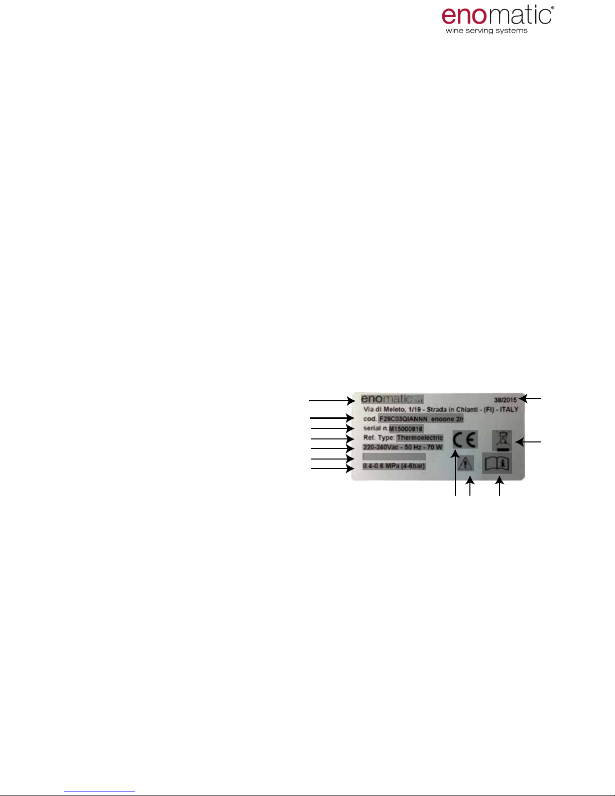
The identication plate shown is applied directly onto the
Dispenser
(one on the rear and
one inside the
Dispenser
under the drip
tray).
It contains the identication references
and all the technical data for safe operation.
1) Manufacturer identication
2) Machine code and model
3) Serial number
4) Type of cooling system
5) Voltage (V) frequency (Hz), absorption (A) or power (W)
6) Fuse characteristics, only if required
7) Operating pneumatic pressure
8) Marking of conformity
9) Danger in case of misuse
10) "read the user manual" warning
11) Disposal indication (Directive 2002/96/CE)
12 Week/Year of production
DO NOT DAMAGE OR REMOVE THE IDENTIFICATION PLATE
1
2
3
4
5
6
7
8 9 10
11
12
INTRODUCTION AND MODEL
Page 7
eno one 2/r - user manual
REV.05
7
5. PACKING AND UNPACKING
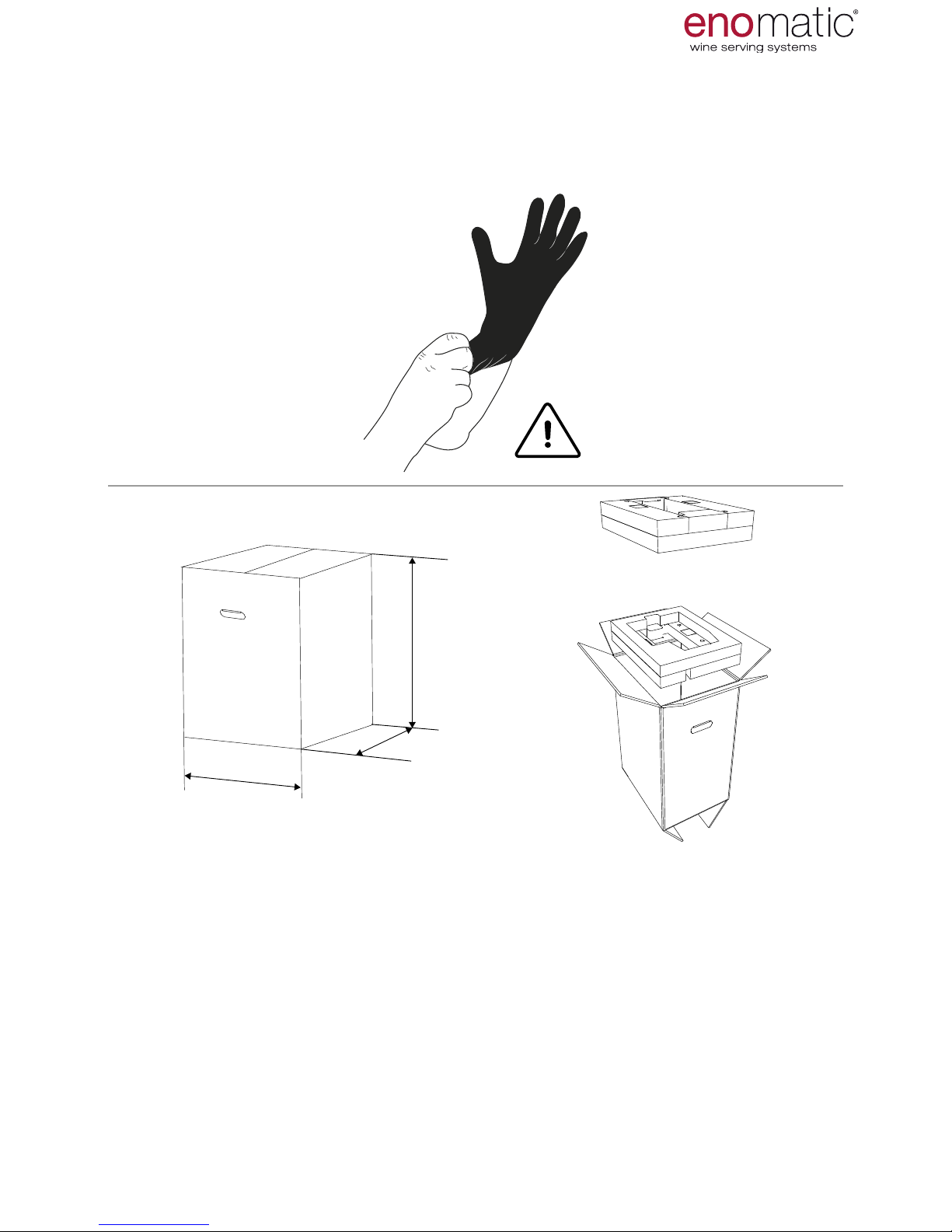
It is advisable to use gloves when removing the Dispenser from the packaging
and for its subsequent handling.
In case of damage or missing parts, do not use the Dispenser but contact your retailer to arrange for the relevant procedure to be adopted.
The Dispenser is sold packed in an appropriate cardboard box with specic anti-shock protectors. Inside the packing the Dispenser is protected by a non-woven
fabric bag.
During unpacking, carefully remove it and check the integrity of the components.
Some of the external and internal surfaces may be appropriately protected with pro-
tective lm which before use should be properly removed.
The package contains all the information necessary to perform movement correctly.
The packaging material, at the Dispenser life end, must be
properly disposed of in compliance with applicable laws.
480 mm
18.90 inch
385 mm
15.16 inch
720 mm
28.35 inch
15 Kg
33,07 lb
PACKING AND TRANSPORTATION
Page 8
eno one 2/r - user manual
REV.05
8
6. PACKING CONTENTS
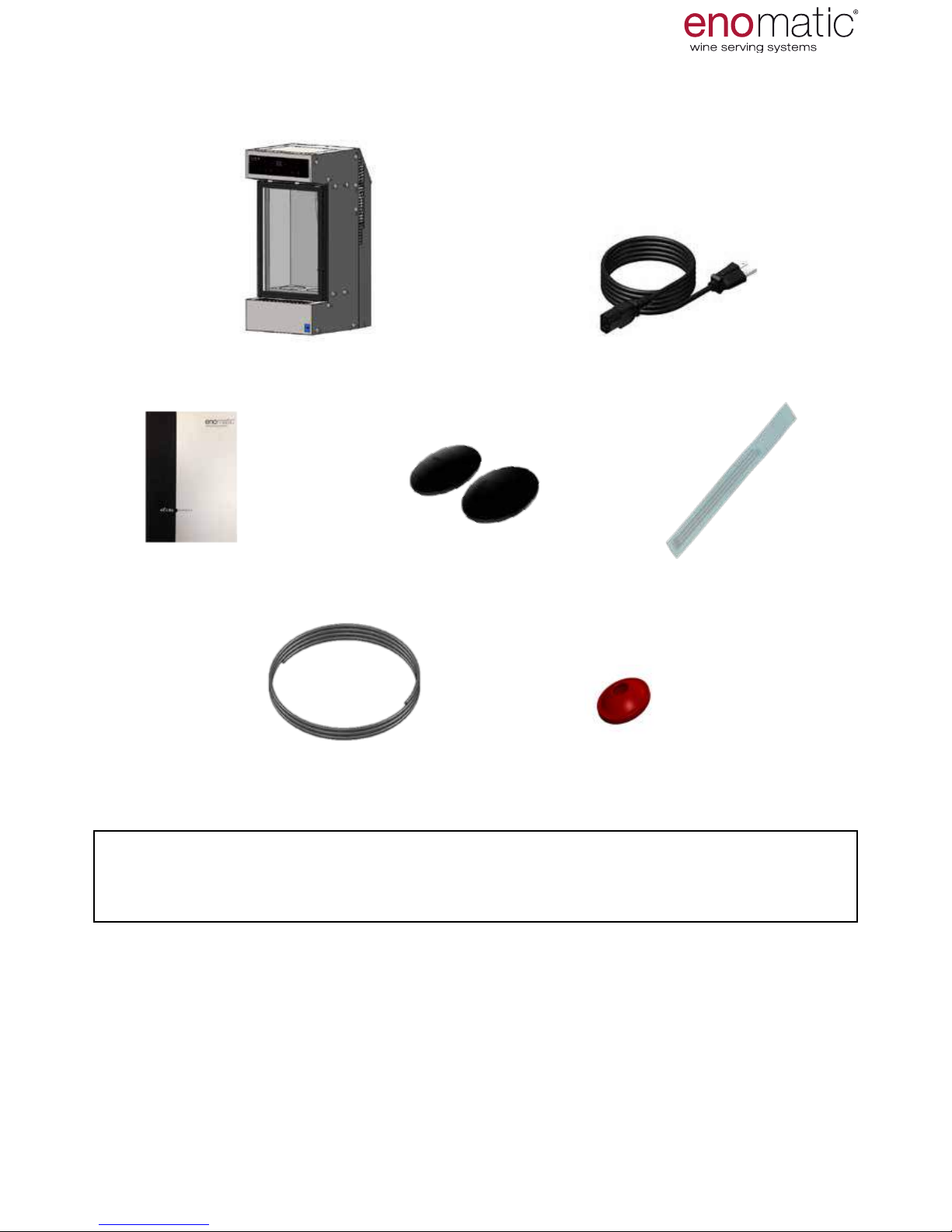
Ensure the following parts are included in the package:
1 x Warnings 1 x suction straws pack
1 x spare seal for a Cap tap1 x gas connection pipe
A Food LLDPE =Ø4x2.5mm
2 x curved coasters
1 x enoone 2/r dispenser 1 x electrical power cord
PACKING AND TRANSPORTATION
Never leave the packaging parts (such as plastic coverings, etc.)
within the reach of children as they may represent a potential hazard
ACCESSORIES ON REQUEST:
• Side panels (black or white)
• Modularity kit
• Spacer for short bottles
• Conditioning partition for 1 white wine and 1 red wine
• Disposable cylinder and pressure regulator
• Cylinder cover casing
• Graduated cylinder to measure doses
For further information contact your authorised retailer.
Page 9
eno one 2/r - user manual
REV.05
9
7. TRANSPORTATION AND STORAGE
Transportation, also depending on the
place of destination, can be performed
with different means.
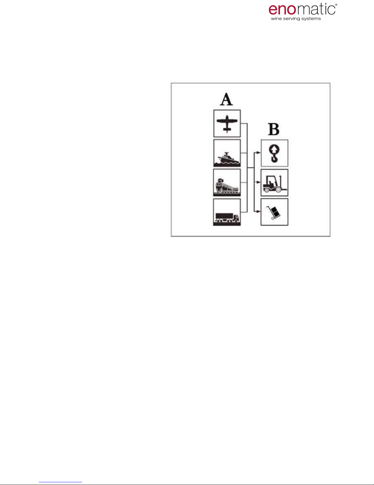
The diagram
shows the most commonly used
solutions.
A) Means of transportation
B) Lifting and handling devices
Storage is required if the dispenser is not installed at the time of delivery. If it must
be stored for a long period, it should be placed in a dry protected environment at a
temperature between 0°C and 40°C (32°F and 104°F) and with humidity maximum
of 65% Hr.
8. LIFTING AND HANDLING
The dispenser is designed for free (stand alone) installation and does not require
particular lifting devices given its low weight.
To move the Dispenser lift it up, holding it from underneath.
Do not push the Dispenser, do not drag it or turn it upside down.
If special needs so require it is possible to use the lifting devices
shown in the image above.
PACKING AND TRANSPORTATION
To protect the Dispenser during the
transportation phases, it is delivered perfectly packaged.
Transportation must be carried out
with the packaging in the vertical
position, as indicated by the symbols directly on it.
The package contains all the information necessary to perform movement correctly. During the movement phase, handle the packaging
carefully and avoid overturning as
this could damage the Dispenser.
Page 10
eno one 2/r - user manual
REV.05
10
9. TECHNICAL CHARACTERISTICS
Kg
12 Kg
26.46 lb
6 °C ÷ 18 °C
276 mm
10.88 in 13.83 in
351 mm
L= 275 ÷ 330 mm
L= 10.83 ÷ 13 in
598 mm
23.55 in
43 °F ÷ 64 °F
ø
< 110 mm
ø
< 4.33 in
ø ≤
90mm
ø ≤
3.54 in
L= 275 ÷ 330 mm
L= 10.83 ÷ 13 in
CHARACTERISTICS AND COMPONENTS
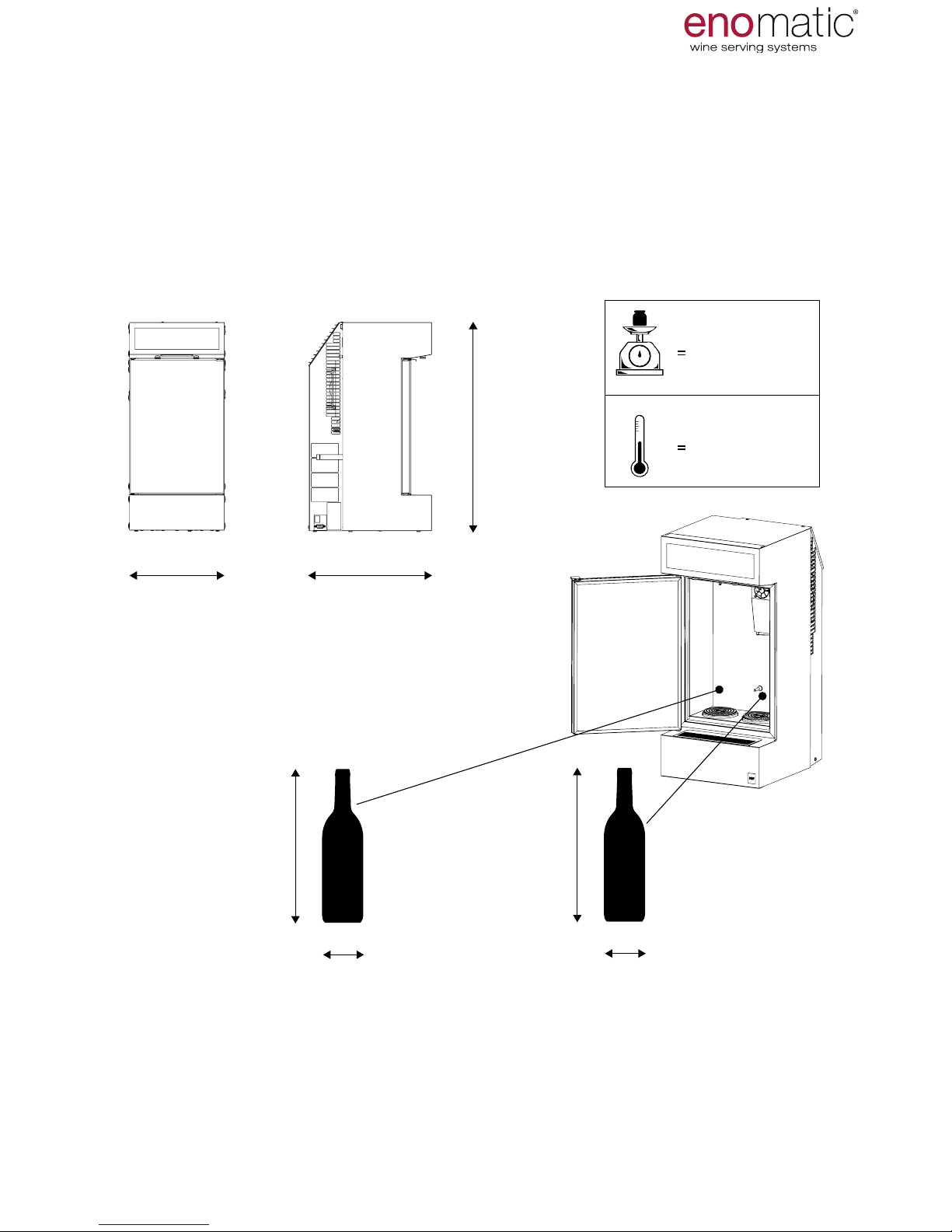
The Dispenser in the sale conguration allows the insertion of bottles with a maximum diameter and a height range indicated in the image below.
The right bottle location (when facing the Dispenser), allows the insertion of bottles
with a diameter less than the left side due to the size of the thermoelectric refrigera-
tion system (O).
Page 11

eno one 2/r - user manual
REV.05
11
A
B
C
D
D
F
G
M
P
D
T3
T4
T2
T1
T
H I L
E
N
O
Q
R
S
U
A.
Display and commands keyboard
B. Door
C. Drip grill with tray
D. Rear air vents
E. Cylinder locking strap
F. Identication plate
G. Data connection port
(for technical use)
H. Inert gas connection
I. Power socket
L. Main switch
M. Door handle
N. Plug tap with seal
O. Thermoelectric cooling
system
P. Bottle compartment
Q. Temperature probe
R. LED
S. Dispensing nozzle
T. Bottle raising piston
T1. Gas spring
T2. Spacer
T3. Cylinder
T4. Curved coaster
U. Foot
10.
COMPONENTS OF THE DISPENSER
CHARACTERISTICS AND COMPONENTS
Page 12
eno one 2/r - user manual
REV.05
12
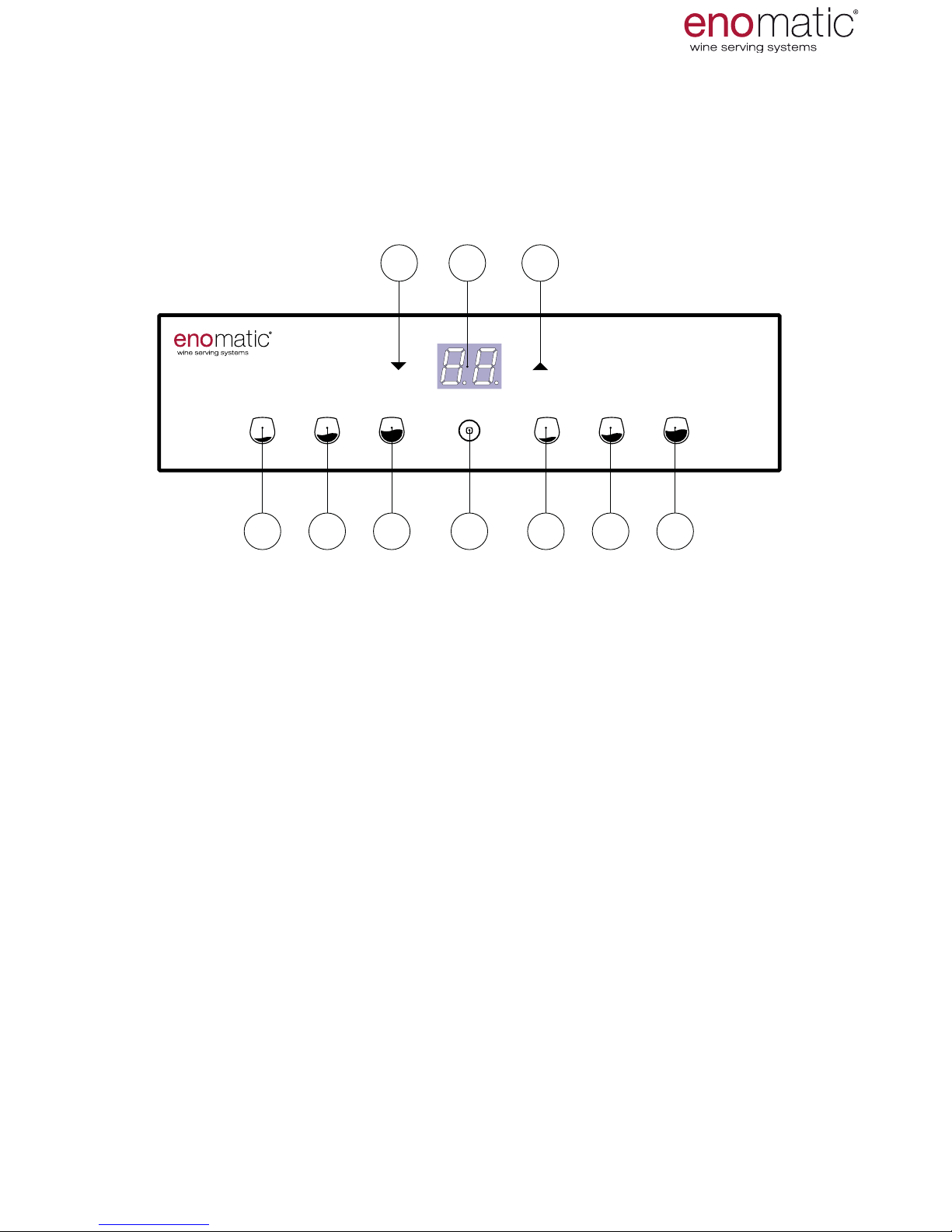
The A-Z references shown on this page and on the previous one,
are mentioned throughout the manual.
V1. Small dose dispensing button (lit)
V2. Medium dose dispensing button (lit)
V3. Large dose dispensing button (lit)
Z. Multifunction button: conrmation, power on/off, output (lit)
X. Increase arrow button
W. Display (lit)
Y. Decrease arrow button
V1 V2 V3 V1 V2 V3Z
XY W
Do not use objects to press the buttons on the keyboard.
use only the ngers of the hand.
11. COMMANDS KEYBOARD AND DISPLAY
CHARACTERISTICS AND COMPONENTS
The keyboard of the dispensers is backlit, as such most of the buttons are
only visible after powering of the dispenser.
Page 13
eno one 2/r - user manual
REV.05
13
12. POSITIONING
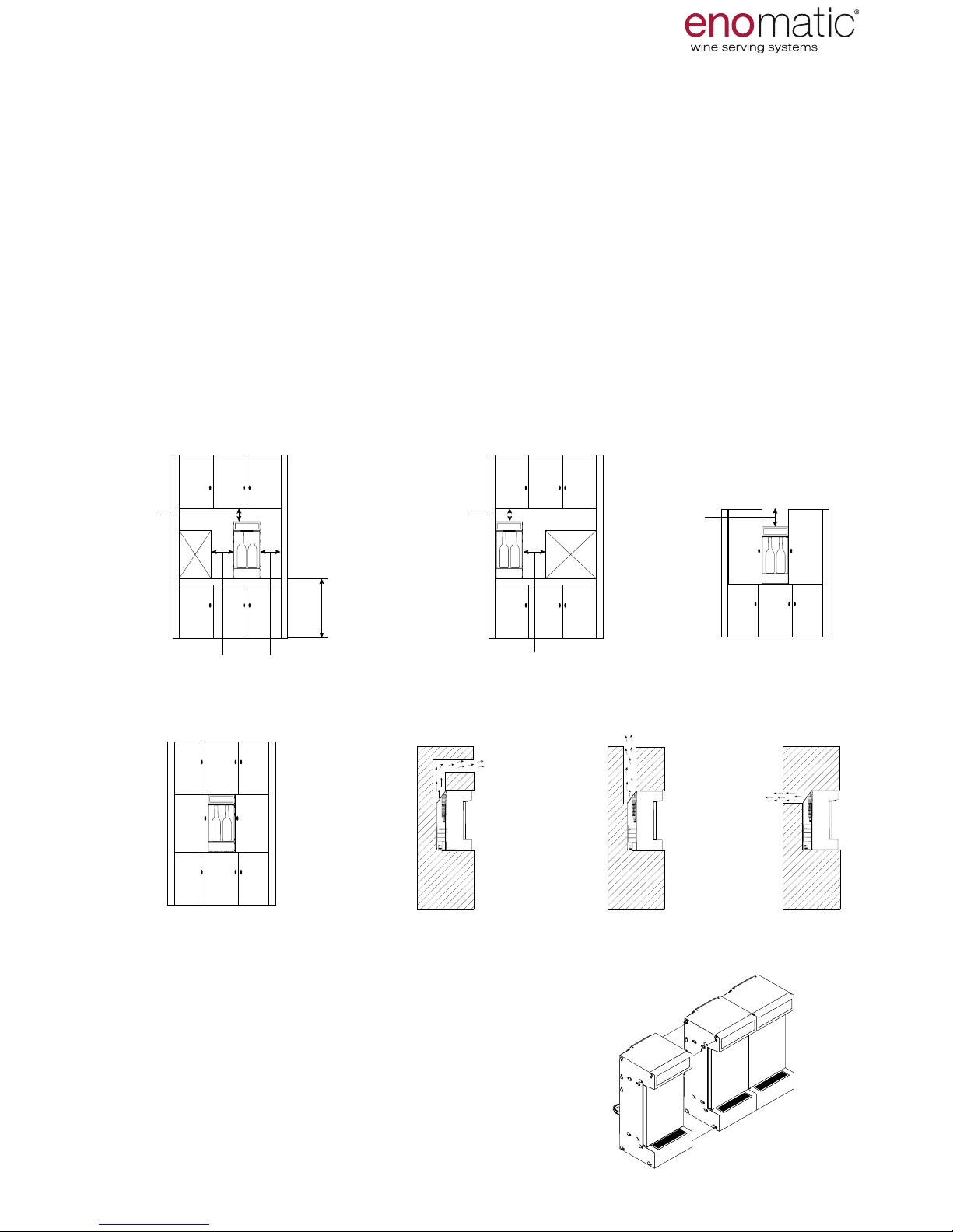
The rst group of images (1) shows the minimum spaces required to
ensure correct ventilation and access to the Dispenser.
In the event of recessing (2), it is necessary to create a structure with an aeration
duct for the circulation of air with a section of at least 100cm2 (15.5in2), directed as in
one of the three examples shown (2.1, 2.2, 2.3).
In this case it is advisable to always consult the retailer before designing the structure to encase the dispenser.
Place the Dispenser on stable and non tilted surfaces.
To facilitate changing, always position the cylinder in accessible places. In the
case of recessing, it cannot be accommodated in the space rear with strap (E)
of the Dispenser but must be placed in a more accessible place (for example
within the cabinet).
Only place the Dispenser
in indoor dry environments and with a maximum temperature of 26°C (79°F), with humidity no greater than 60% and away from heat
sources.
MODULARITY
Enoone
is a modular dispenser that can
be anked, using a suitable side mounting
system, to another Dispenser of the same
model, that can also be connected to a single
source of gas.
For more information, contact the
retailer.
≥ 20 mm
≥ 0.79 in
≥ 10 mm
≥ 0.39 in
≥ 10 mm
≥ 0.39 in
≥ 20 mm
≥ 0.79 in
≥ 900 - 1000 mm
≥ 35.43 - 39.37 in
≥ 20 mm
≥ 0.79 in
≥ 40 mm
≥ 1.57 in
INSTALLATION
1
2
2.1
2.2
2.3
Page 14
eno one 2/r - user manual
REV.05
14
250 mm
9.85 inch
352 mm
13.86 inch
AIR OUTLET
COOLING
AIR INLET
COOLING
14. CONNECTING THE GAS
The operations described below must be carried out by personnel
authorised by the manufacturer or who have been adequately trained.
The use of gloves during the operations to connect the gas and to
replace the cylinder is recommended.
The Dispenser must be connected to a source of food-use inert gas, see table
below.
GAS PERMITTED
Argon (E938) Nitrogen (E941)
The gas is not supplied together with the Dispenser and can be purchased directly
from the Enomatic retailer or from an authorised retailer of food-use gas in the con
-
tainers described below:
•
Disposable cylinder
•
Rellable cylinder
In the event of high use of the Dispenser, it is advisable to use a
Nitrogen Generator that is exclusively available from the retailer Enomatic.
Ask the retailer for information on the best choice to suit
your needs.
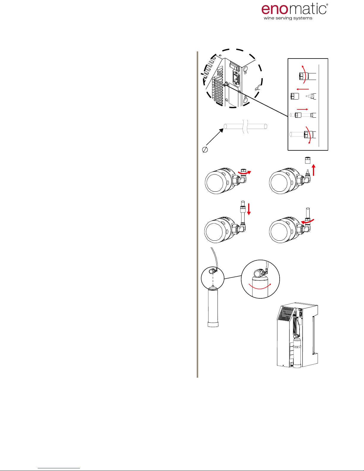
THE FOLLOWING EXAMPLE ILLUSTRATES THE STEPS TO CONNECT A DISPOSABLE CYLINDER WITH ITS PRESSURE REGULATOR TO THE DISPENSER
The gas connection pipe, supplied with the Dispenser (para. 6), is delivered to you
in a length of 0.70 m / 27.56 in, to place the cylinder in the relevant rear space accompanied by the strap (
E
). To position the cylinder away from the Dispenser and
to accommodate it, for example, inside the door of any cabinet on which you will be
positioning the Enomatic device, contact the Retailer with regard to the gas connection pipe of the desired length.
INSTALLATION
13. THERMOELECTRIC REFRIGERATION SYSTEM
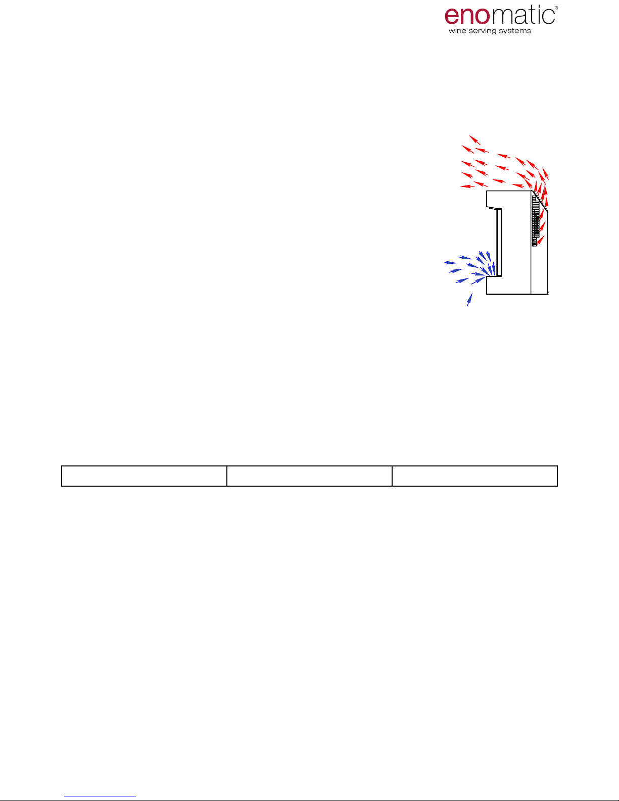
The dispenser has a thermoelectric refrigeration system (O) controlled by an electronic board which regulates the temperature of the bottle compartment via a detection probe (Q). The system draws in the air from the drip grill (C) and expels it
through the rear aeration grills (D). Do not place any object on or within the com-
ponents (C) and (D), check constantly that they are not blocked.
Clean the grills constantly referring to the
scheduled maintenance table
(para. 41)
and perform the recommended
daily and
annual cleaning (para. 48.
Do not leave the cooling system activated with the door open. During operations on Dispenser that involve
continuous or protracted openings of
the
door, such as emptying of the ducts or
replacement of the bottle, it is recommended to switch off the refrigeration
setting the temperature to "OFF" = off
(para. 23).
IMPORTANT
For correct operation and duration over time, carefully follow the information
indicated above.
Page 15
eno one 2/r - user manual
REV.05
15
10
1
2
3
4
10
12
1. Unscrew with your ngers the safety nut
from the tting of inert gas connection ( H
).
2. Remove the safety nut from the tting.
3. Take one end of the gas connection pipe,
insert it within the safety nut and connect
the pipe by pushing it with force as far as
possible on the inert gas connection tting
(H), being careful not to tilt the Dispenser.
4. Tighten the nut to secure the pipe by
squeezing it as much as possible with your
ngers.
5. Take the pressure regulator to the dispos-
able cylinder (gure to the side)
6. Unscrew with your ngers the safety nut
from the cylinder pressure regulator con-
nection tting
.
7. Remove the safety nut.
8. Insert within the safety nut the other end
of the pipe and connect it with force to the
tting, pushing it to the end.
9. Tighten the nut to lock the pipe, squeezing
it as much as possible with your ngers.
10. Place the bottle on the working surface, remove the plastic protective cap
and screw it quickly down to the bottom
of the pressure regulator (rotate the cyl-
inder while holding the regulator still
to prevent the gas connection pipe
from twisting). A small leak during the
screwing stage is in any case envisaged
therefore at this phase accelerate tightening.
11. Open the pressure regulator valve to
minimum 4 Bar and maximum 6 Bar.
12. Place the bottle in the appropriate rear
space of the Dispenser, supporting the
base on the surface and fasten it with the
specic locking strap (E) or place it close
to the Dispenser.
6
8 9
7
INSTALLATION
1
2
3
4
= 4 X 2,5 mm
Should it be necessary to disconnect the Dispenser from the gas supply, never
directly extract the pipe from the machine without rst having closed the valve
on the pressure regulator. Close the regulator valve. Only unscrew the cylinder
from the pressure reducer if it is tted with a safety needle valve.
DISPOSABLE PERFORATION CYLINDERS MUST NEVER BE
REMOVED BEFORE THEY ARE COMPLETELY EMPTY
Carefully read all of the safety guidelines of the cylinder (container under pressure) before manipulating it.
Page 16
eno one 2/r - user manual
REV.05
16
15. ELECTRICAL CONNECTION
Before connecting the Dispenser to the electrical mains, always check the compat-
ibility of the voltage comparing it with the data indicated on the identication plate
(F).
For safely reasons, it is absolutely essential that the Dispenser is
connected to an electrical network equipped with an effective earthing system, performed in accordance with the legal technical regulations.
Ensure the Dispenser does not experience power surges due to interference
from other equipment connected to the same electrical network that could
alter the normal functioning of its electronics.
Before connecting the plug to the electrical mains, check that the main switch
(L) is in the "0" = OFF position.
Insert the power supply cable into the socket (I)) of the Dispenser.
Insert the plug of the supplied cable into the wall socket.
INSTALLATION
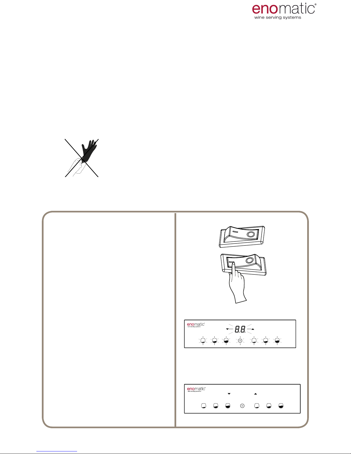
From now on, it is possible to continue without
using gloves.
Place the main switch
(L) in position
"I" = ON
The Dispenser starts and performs
a functional check, indicated by
the simultaneous ashing of all the
buttons (V) and of the display (W).
The LED (R) comes on.
After a few seconds, the Dispenser passes to the operating status
illuminating only the active
Dispensing (V) buttons with activation of the thermoelectric module function for refrigeration of the
bottle compartment (P).
> 10”
3”
16. POWERING THE DISPENSER
After having installed the Dispenser the next step is switch on
and its use.
Page 17
eno one 2/r - user manual
REV.05
17
17. SECONDARY (STAND-BY)
ON/OFF
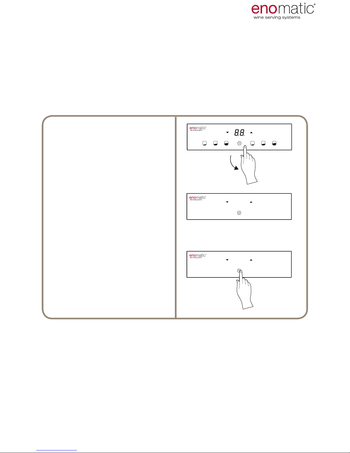
The Dispenser can also be switched on and off with the conrmation button (Z),
when the main switch (L), present on the rear panel, is not easily accessible.
In stand-by mode the Dispenser is actually switched off (dispensing is not permitted and refrigeration is disabled) even if powered by the electric mains.
From the operating state press the
multifunction button (Z) until 8.8.” appears on the display after the display
of "F1"
When the button is released, the Dispenser
switches off leaving only the
lit conrmation button (Z) on.
Rest condition (stand-by)
To switch on the Dispenser from the
stand-by condition, simply press the
conrmation button (Z) until power-
ing of the display.
USE AND OPERATION
Page 18
eno one 2/r - user manual
REV.05
18
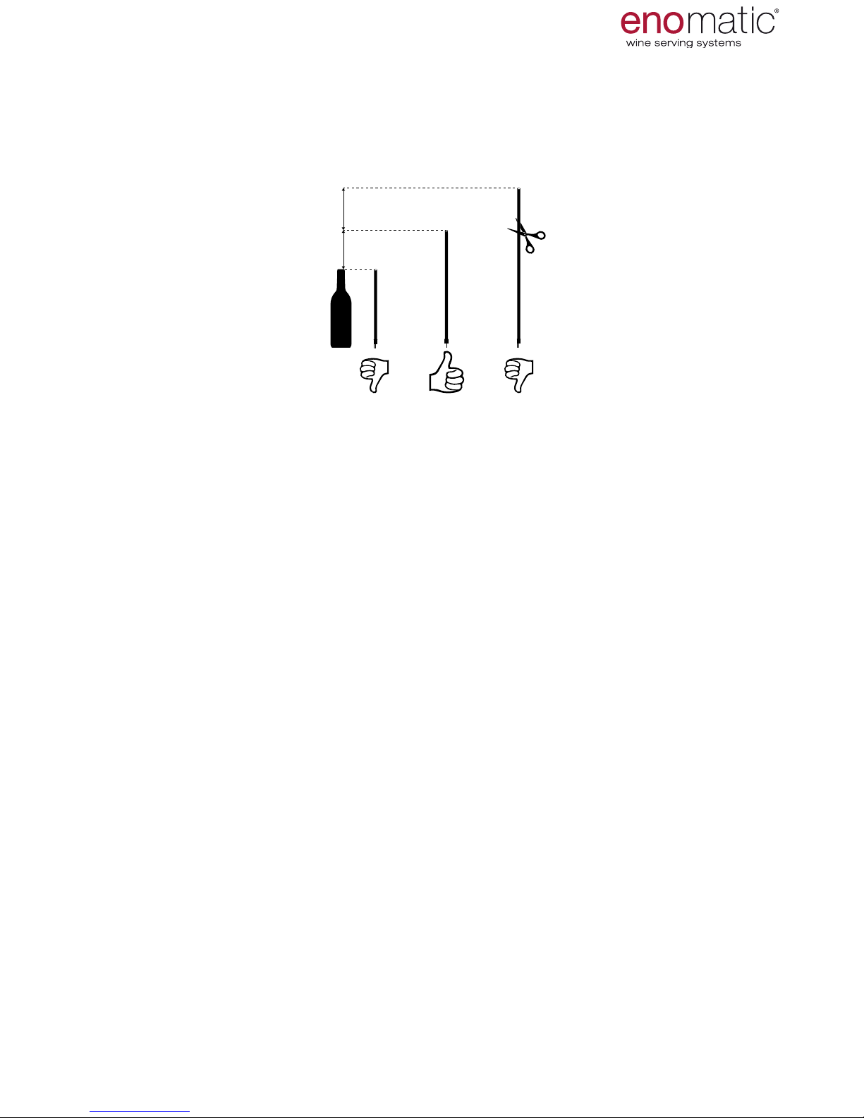
Before insertion into the bottle ensure the correct length of the straw. Place the
straw next to the bottle to be inserted. The recommended length of the straw must
be at least 2 cm (0.79 in) higher than the length of the bottle and
never more than 5 cm (1.97 in).
If the straw is longer, cut it using a pair of scissors.
A straw that is too long could bend inside the bottle
limiting the passage of the liquid possibly resulting in its complete obstruction.
If the length is less than that suggested, replace the straw with one that is adequate. An overly short straw will not allow dispensing of all the liquid
inside the bottle.
Always replace straws that are deteriorated from use. (e.g. torn, deformed).
Further straws can be obtained from the retailer Enomatic.
18. RUBBER STRAW MEASUREMENT
no.3 rubber straws are supplied, necessary to remove the wine from the inside of
the bottle and to convey it to the plug tap (N) of the
Dispenser unit. The end of the straw where the lter that restricts the passage of
wine sediments is located must be inserted into the bottle while the other end must
be connected to the plug tap.
2÷5 cm
0.79÷1.97 in
>5 cm
>1.97 in
19. FUNCTIONS MENU
The Dispenser has a menu with features that are useful to set the main parameters
and in order to interact with it. To access the Functions menu press the multifunc-
tion button(Z) for 3 seconds and release it as soon as the letters "F1" are displayed.
Scroll with the arrow buttons (X,Y) to select the desired setting
and then press the multifunction button (Z) once.
to access the specic function. The operation described above must be carried out
within a few seconds otherwise the Dispenser will automatically trigger the time-out
mode, returning to the previous menu without having stored any function/parameter.
Below is shown the correspondence of the functions to the related acronyms displayed on the lit display (W):
F.1
BOTTLE INSERTION
F.2
TEMPERATURE SCALE SETTING
F.3
DOSE MODE SETTING
F.4
DOSE PROGRAMMING
F.5
LED INTENSITY SETTING
F.6
WASHING AND SANITISING
F.7
DISPENSER VERSION
USE AND OPERATION
Page 19
eno one 2/r - user manual
REV.05
19
For the initial and correct insertion of the bottles and for subsequent replacements
of the bottles, follow the steps described below. In particular the centring and stabilisation activities must be performed well to quickly replace bottles, as described in
the bottle replacement/extraction paragraph (para. 21)
It is recommended that the temperature of the bottles to be inserted only differ by a maximum of 4°C (7.2°F) from the value set for the bottle compartment
(para. 23).
3’’
3’’
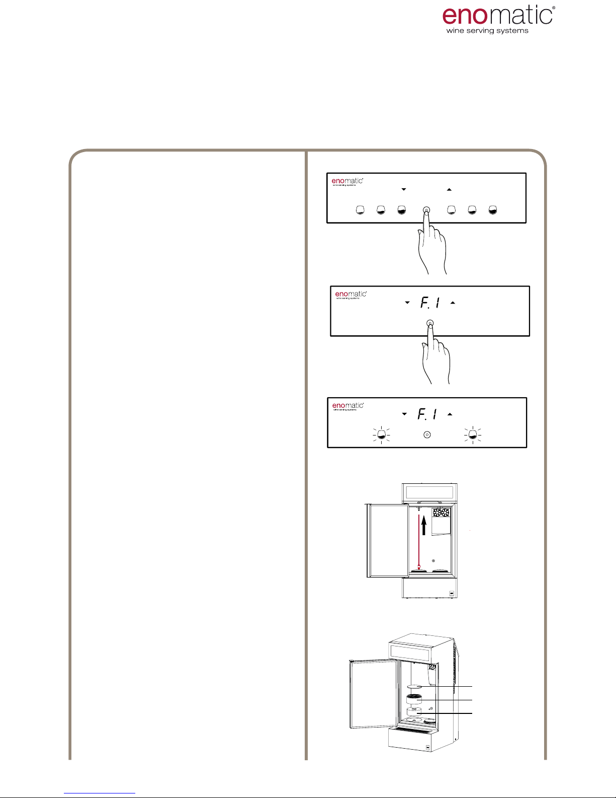
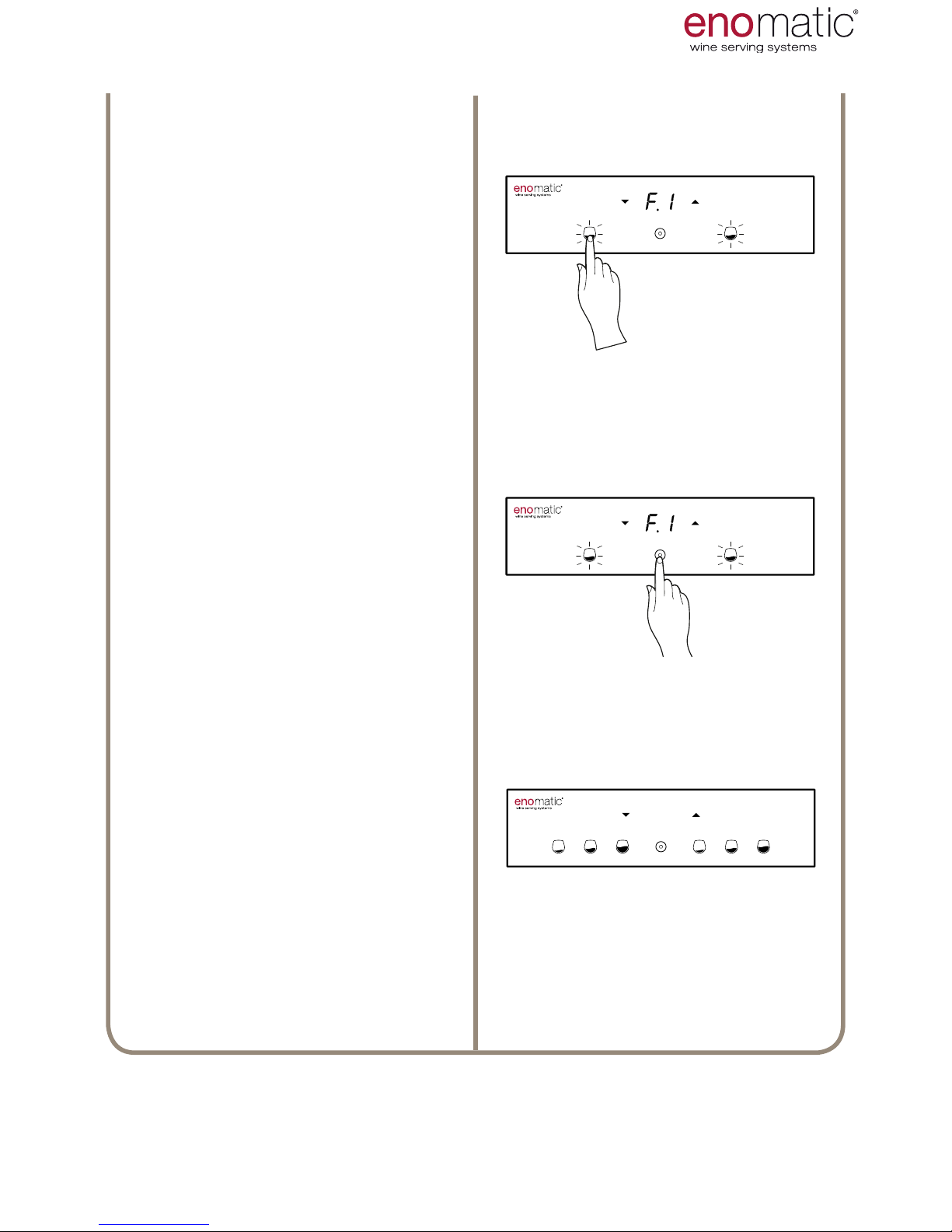
20. F.1 BOTTLE INSERTION
3’’
T3
T4
T2
From the operating state
Press
the multifunction button (Z) for 3
seconds and release it as soon as
the letters "F1" are displayed.
Press the multifunction button (Z) to
access the function chosen.
The Dispenser is on hold for loading
of the bottles after which the medium
dose button (V2) of each dispensing
unit will ash. During this function
refrigeration is switched off to limit
energy consumption.
The Dispenser remains in this position for 10 minutes, after which it
automatically returns to the operating
state.
Open the door (B) and insert the suction pipe on the relevant
nozzle of the plug tap (N),
pushing rmly until it is fully inserted.
Repeat the same operation for the
other position.
Check for the presence of a
spacer (T2) and of a cylinder (T3).
Place on the cylinder
a curved coaster (T4) supplied
with the Dispenser (para.10 ). Repeat
the same operation for the other position.
When inserting bottles with a at
bottom remove the curved coaster.
USE AND OPERATION
Page 20
eno one 2/r - user manual
REV.05
20
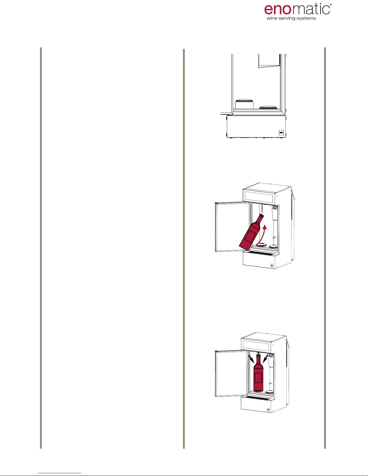
Make sure that the
bottle raising pis-
ton
(T) is in lock position (1).
Where the
bottle raising
piston (T)
is in an elevated position (2) push it
down with your hand as far as the
lock position (1).
(2) (1)
Insert the straw into the bottle
being careful not to bend it and rest
the bottle on the raising piston (T).
Take the base of the neck of the
bottle with both hands and push it
downwards, exerting a pressure in
order to release the bottle raising
piston (T) and to enable its ascent.
Accompany the bottle until its mouth
is resting on the seal of the plug tap
(N).
USE AND OPERATION
Page 21
eno one 2/r - user manual
REV.05
21
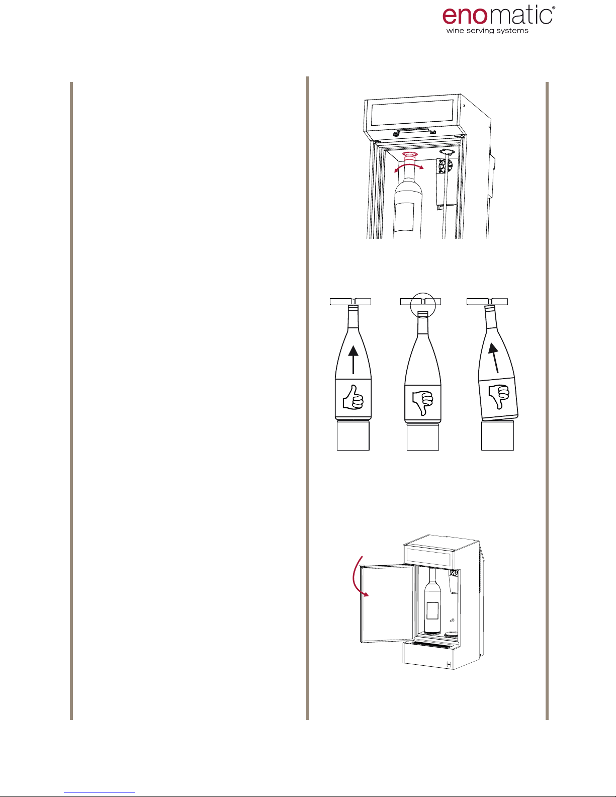
Having positioned one or
both bottles, close the door.
1 2 3
Twist the bottle slightly to the right
and left to stabilise and centre it.
Perfect adhesion of the neck of the
bottle on the seal of the
tap plug N) is indispensable for
correct operation and to avoid gas
leakage.
(example no. 1)
In case no. 2, which can be found
with bottles with heights lower than
the standard, introduce one or more
spacers,
that can be purchased as accessories
from the retailer Enomatic.
USE AND OPERATION
Page 22
eno one 2/r - user manual
REV.05
22
Press the medium dose dispensing
button (V2) corresponding to the
point of insertion of the bottle.
The system will insert into the bottle
an amount of inert gas to preserve
the wine. A light "click" will be heard.
In the case of insertion of a second
bottle repeat the same operation for
the other station
To avoid wasting gas do not press
the buttons where no bottle has
been loaded.
Press the
multifunction button (Z) for at least 3
seconds and release it
as soon as the letters "F.1" disappear
to exit the function.
The Dispenser will enter
dispenser mode.
Refrigeration of the bottle compartment will be reactivated.
3’’
click
3’’
click
3’’
click
USE AND OPERATION
Page 23
eno one 2/r - user manual
REV.05
23
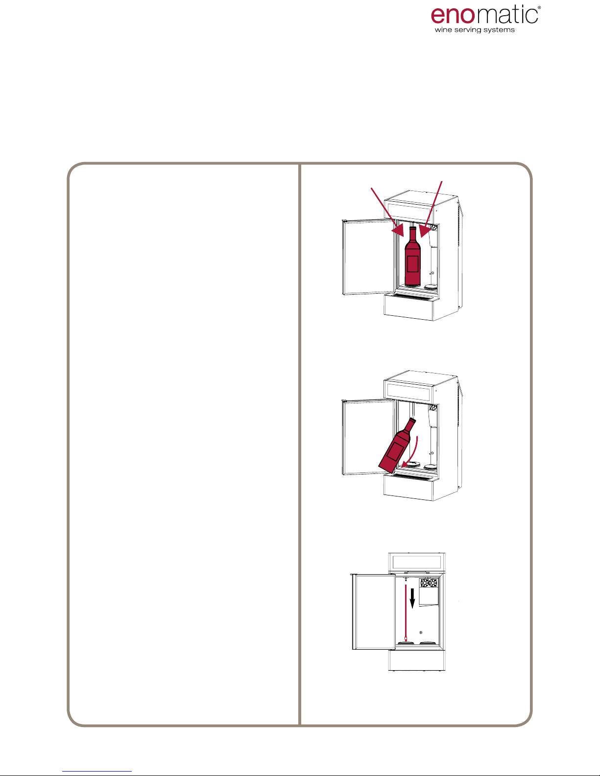
21. REPLACEMENT/REMOVAL OF THE BOTTLE
In the event of replacement it is advisable to enter the "F.1" menu to
momentarily deactivate the thermoelectric component and thus avoid energy consumption and accumulation of condensation inside the bottle compartment (P).
This process can however be avoided in the event of rapid replacement.
In case of removal (without replacement) there is no need to enter the "F.1 " menu.
For both operations follow the steps described below:
Open the door (B) and push the bottle down, exerting pressure with the
hands on the base of the neck in
order to lock the bottle raising piston
(T) into the locked position.
Keep the door (B) open for the
shortest possible time in order to
avoid dispersion of the temperature of the bottle compartment (P)
and the formation of condensation.
Dry any moisture which forms on
the inside of the compartment and
on the bottles every time the door is
opened.
Remove the bottle from the straw
avoiding the leaking of drops of wine.
The straws can be reused with different wines, after having checked the
length (para.18 ). In this case it is advisable to clean the straw (para. 43 ).
When replacing the same wine it is
possible to avoid washing the pipe.
USE AND OPERATION
Page 24
eno one 2/r - user manual
REV.05
24
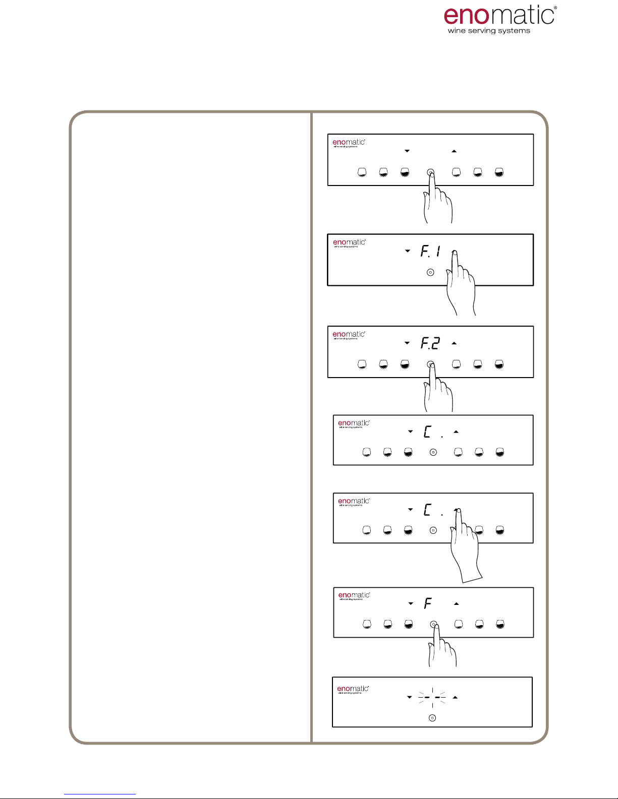
From the operating state press the
multifunction button(Z) for 3 seconds
and release it as soon as the letters
"F1" are displayed.
Scroll with the arrow buttons (X, Y)
to select the function "F.2"
Press the multifunction button (Z) to
access the function chosen.
The Dispenser will display the current
setting, highlighting it with
a point “ .”
Scroll with the arrow buttons (X, Y)
to select the desired setting between
“6÷18/OF” .
Press the multifunction button (Z) to
save the setting.
Flashing of the
display lines conrms successful
saving of the setting.
3’’
3’’
3’’
22. F.2 TEMPERATURE SCALE SETTING
[default setting °C]
It is possible to set the temperature measurement unit in degrees Celsius °C,
shown on the display with “C” or in degrees Fahrenheit °F, shown on the display with “F”
USE AND OPERATION
Page 25
eno one 2/r - user manual
REV.05
25
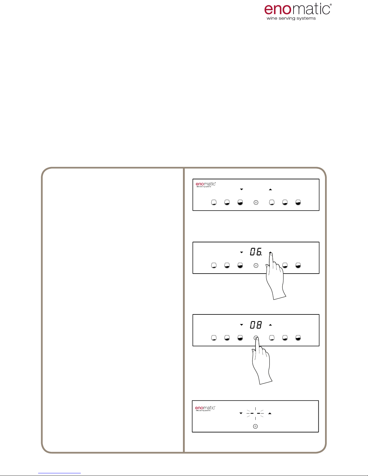
From the operating state, press the
arrow buttons (X, Y), the Dispenser
will display the current setting, highlighting it with a point “ .”
Scroll with the arrow buttons (X, Y)
to select the desired setting between
“6÷18/OF” or “43÷64/OF”
Press the multifunction button (Z) to
save the setting.
Flashing of the display lines conrms
successful programming of the setting.
23. TEMPERATURE SETTING
[default setting 10 °C]
The temperature setting of the bottle compartment (P) is the only parameter which
is accessed directly without having to enter the functions menu.
The temperature that can be set is between 6°C (43 °F) and 18°C (64 °F). It is possible to set the unit of measurement of temperature in degrees centigrade (°C) or
degrees Fahrenheit (°F) consulting para. 22.
Switch off refrigeration of the bottle compartment by setting the value to "OF"= OFF, that
is located before the value " 6" ("43") and after the value "18" ("64"). This mode is recommended when the temperature of the room in which the Dispenser is located is similar
to the temperature of the wine in question. Whenever the refrigeration is switched off it
is necessary to keep the door open and to dry the moisture as stated in para. 42.
The ability to reach the temperature of the bottle compartment (P) is inuenced by
external environmental conditions, therefore only place the Dispenser in indoor
dry environments and with a maximum temperature of 26°C (79°F), with humidity less than 60% and away from heat sources.
USE AND OPERATION
Page 26
eno one 2/r - user manual
REV.05
26
USE AND OPERATION
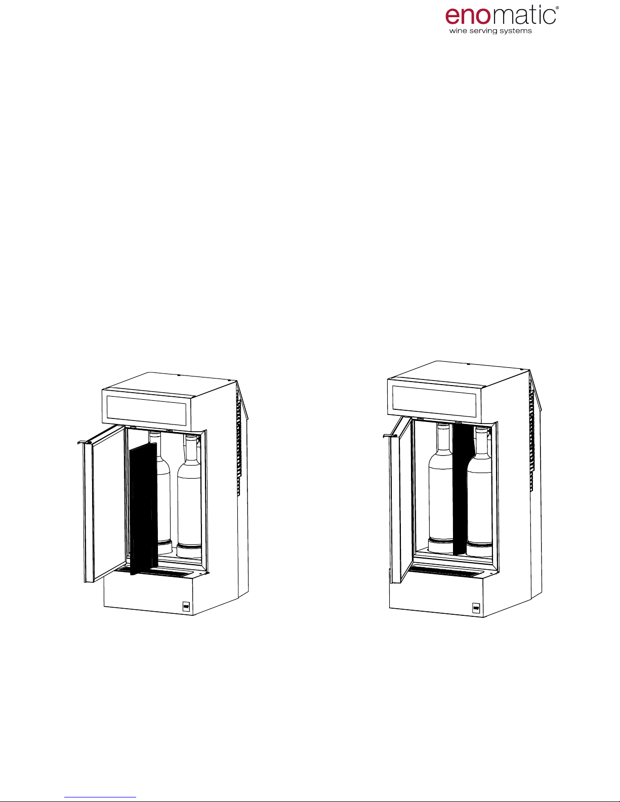
CONDITIONING PARTITION
The conditioning partition accessory accommodates within the Dispenser two
types of wine which require different temperatures.
This accessory is not supplied with the Dispenser and can be obtained from your
Retailer.
Looking at the front of the Dispenser, insert into the right position the bottle of
wine that requires a lower temperature (e.g. white wine +8°C/46,4°F) and in
the left position, a bottle of wine that requires a higher temperature (red wine
+18°C/64,4°F).
The difference in temperature between the right compartment (temperature controlled) and the left one (derived temperature) will be approximately 8°-10°C
(14,4°-18°F) in conditions of ambient temperature of approximately 25°C (77°F).
Page 27
eno one 2/r - user manual
REV.05
27
USE AND OPERATION
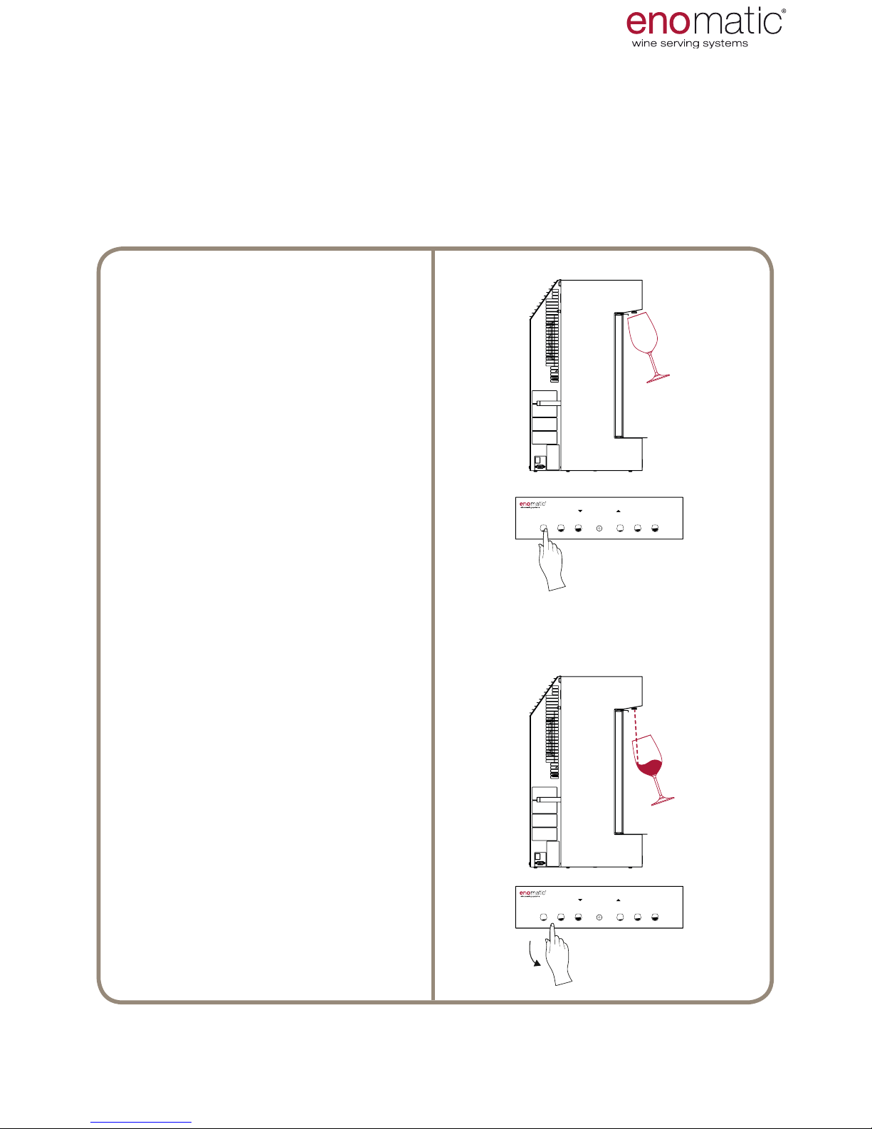
Place the glass under the dispensing nozzle (S) tilting it slightly.
Press the dispensing button only
once. In the case of programmed
dose "PO", instead hold down the
button for free dose "FE" (para.
25)
Do not dispense before having
positioned the glass under the
respective nozzle.
Wait a few seconds with the glass
under the dispenser after the end
of dosing.
The Dispenser does not have
devices that detect when there is
no longer any wine in the bottle.
As such, pay attention to the last
dispensing in the event that the
amount of residual wine is below
the dose chosen. Finishing of
the liquid during dispensing
involves a signicant escape of
gas that is easily recognisable
by an irregular and loud ow
(intermittent spraying). It is
therefore necessary to follow
these instructions:
• In the case of free dose
immediately, release the dose
button (V).
• In case of programmed dose,
immediately press the dose
button (V).
The Dispenser has 2 dispensing units that preserve the wine in the bottles that
have been introduced and to remove it by means of the rubber straws, dispensing
it into the glass. It is possible to dispense immediately after having introduced the
bottles (para. 20) by simply pressing one of the dose dispenser buttons (V).
The dispenser enables simultaneous dosing from the two dispensing nozzles (S).
24. DISPENSING
Page 28
eno one 2/r - user manual
REV.05
28
25. F.3 FREE OR PROGRAMMED DOSE SETTING
[PO default setting]
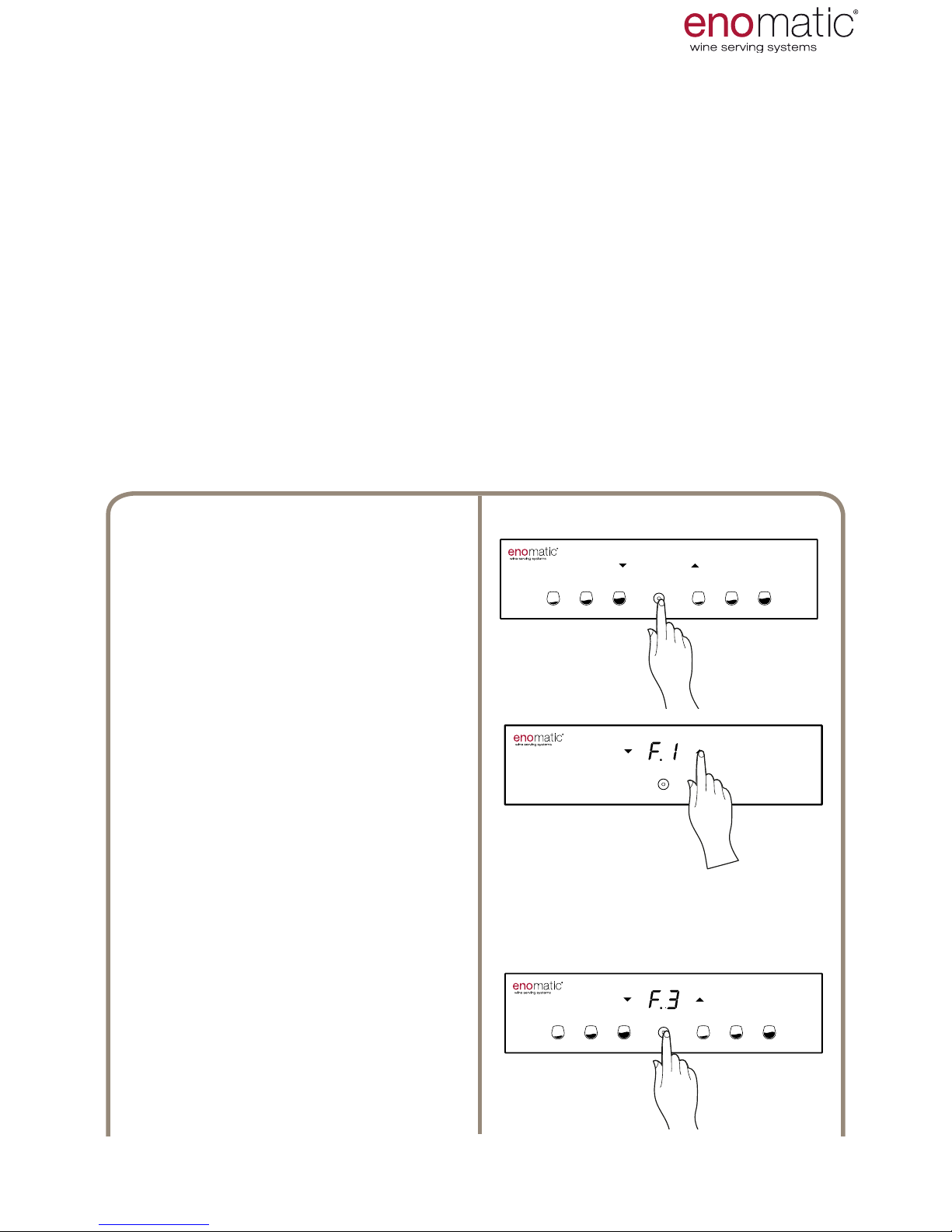
From the operating state press the
multifunction button(Z) for 3 seconds
and release it as soon as the letters
"F1" are displayed.
Scroll with the arrow buttons (X, Y)
to select the function "F.3"
Press the multifunction button (Z)
to access the function chosen.
3’’
3’’
The dispenser can provide wine in two different modes.
• FREE DOSE "FE": Dispensing starts with pushing only of the medium dose
button (V2) of the two dispensing units and ends with its release. Hold the
button until the desired quantity is provided.
• SCHEDULED DOSE "PO"
: When the dose button (V), is pressed, the Dis-
penser provides the pre-set quantity with the default values, pressing again
during dispensing instantly interrupts the dosing in progress. The following are
the default programmed doses:
USE AND OPERATION
Small dose.........30ml [1.06 .oz] ± 3%
Medium dose.......60ml [2.11.oz] ± 3%
Large dose..........90ml [3.17 .oz] ± 3%
(values found at start of bottle)
Page 29
eno one 2/r - user manual
REV.05
29
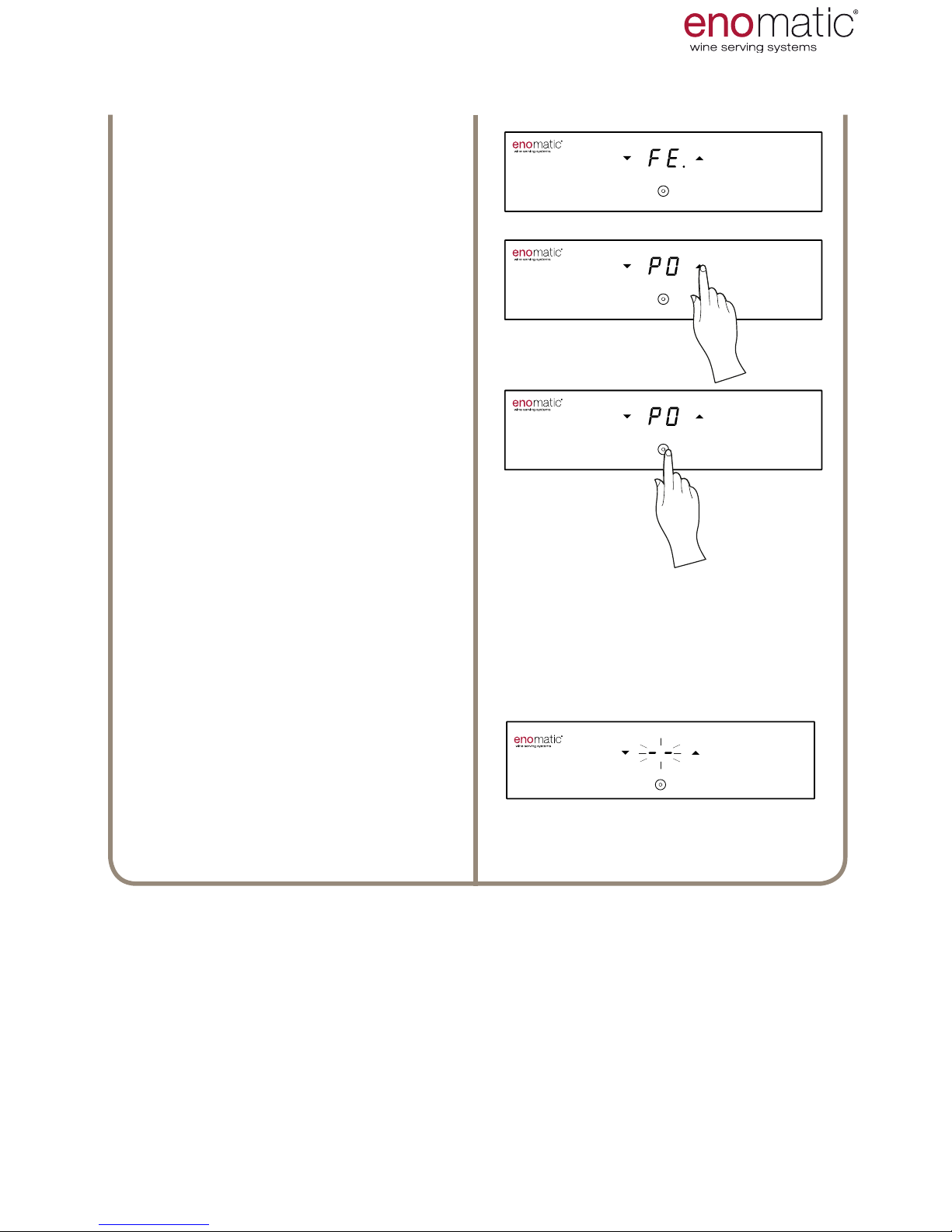
The Dispenser will display the current
setting, highlighting it with a point “
.”
Scroll with the arrow buttons (X, Y)
to select the desired setting between
“PO/PE”.
Press the multifunction button (Z)to
save the setting.
Flashing of the display lines conrms
successful programming of the setting.
USE AND OPERATION
Page 30
eno one 2/r - user manual
REV.05
30
26. F. 4 TYPES OF PROGRAMMED DOSES
[dF default setting]
In addition to the default settings "PO" (para. 25), the programmed doses can also
be recorded as chosen by the user in the following ways:
Copy "CO" allows the storing of 3 doses different from each other (small, medium
and large) on one of the two dispensing units and to then copy them automatically
onto the adjacent one (para. 28).
Not Copy “nC” allows to store 3 doses different from each other (small, medium
and large) and completely different between one dispensing unit and the other
(para. 29).
Copy All “CA” allows the storing of one unique dose from the medium dose button (V2) on one of the two dispensing units and to then copy it automatically onto
the adjacent one (para. 30).
In order to reset the default settings
Default “dF” follow the instructions shown in para. 27.
USE AND OPERATION
It is advisable to perform programming of the doses with a bottle of water in
order to avoid wasting the wine. In this case, the doses of wine may not correspond exactly to the doses pre-set with water, given the different densities
and temperature between the two liquids.
Before proceeding to programming of the doses there-
fore, ll a 0.750 l (26.4 .oz) wine bottle with drinking
water (2 bottles are only required in the “Not Copy”
“nC” case) to set/change the doses.
Insert the bottles of water following the bottle insertion
procedure (para. 20) and dispense, again just the once,
the large dose (V3).
Dispensing after insertion is essential in order to ll the
ducts of the dispensing unit for precise storage of the
dose.
To measure the desired quantity it is recommended to
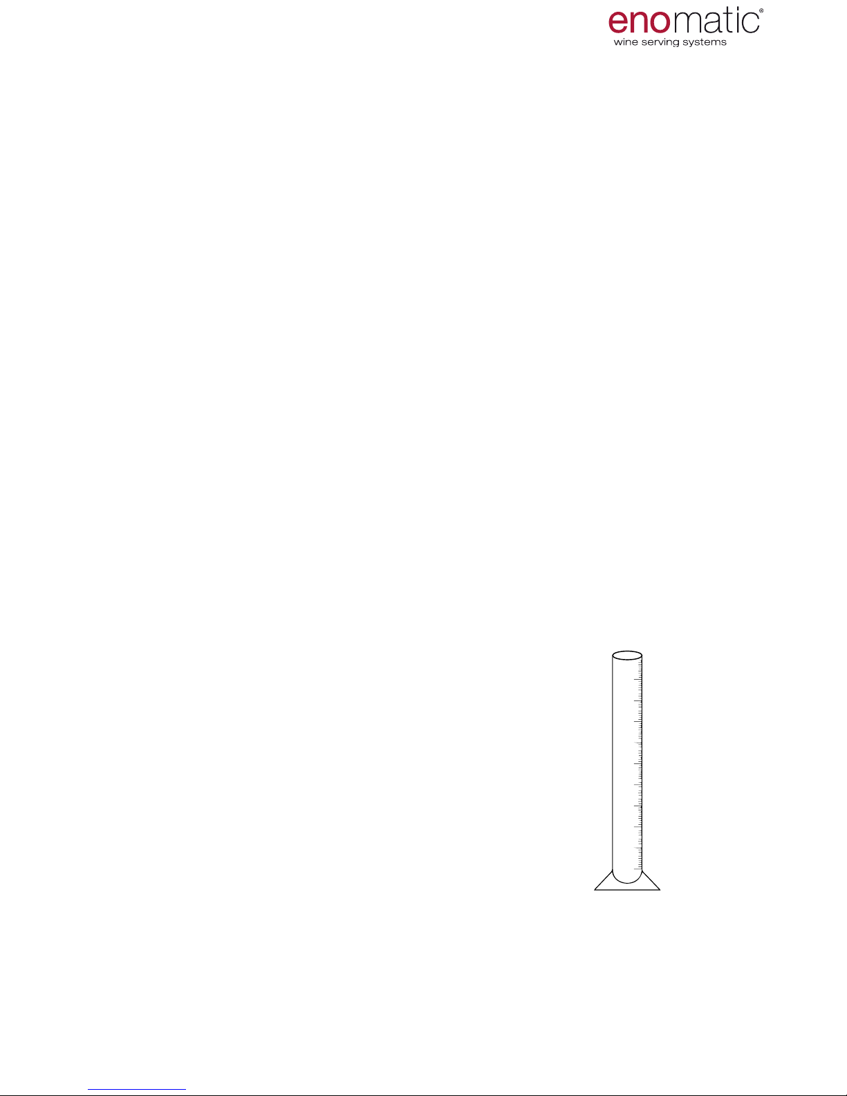
use a graduated cylinder, sold by Enomatic reteiler.
Page 31
eno one 2/r - user manual
REV.05
31
3’’
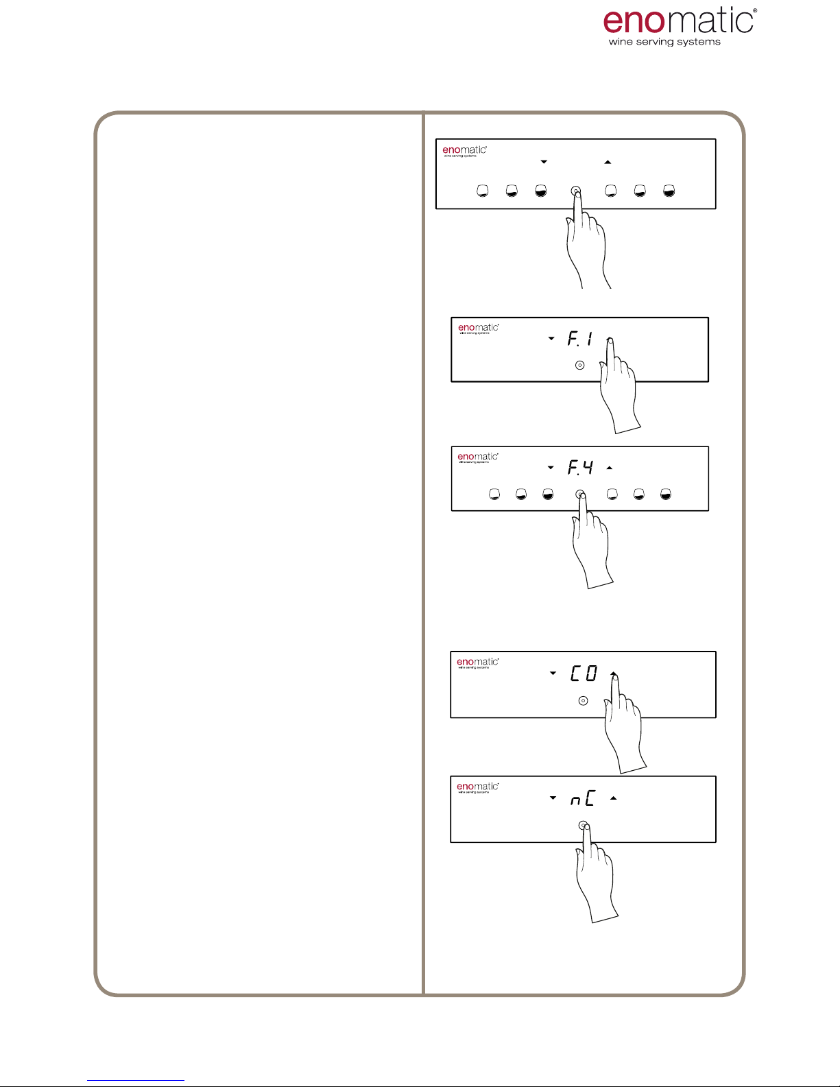
From the operating state press the
multifunction button(Z) for 3 seconds
and release it as soon as the letters
"F1" are displayed.
Scroll with the arrow buttons (X, Y)
to select the function "F.4".
Press the multifunction button (Z) to
access the function chosen.
The Dispenser will display the current
setting, highlighting it with a point “
.”
Scroll with the arrow buttons (X, Y)
to select the desired setting between
“CO/nC/CA/dF”.
Press the
conrmation button (Z)to save
the setting.
27. SETTING OF PROGRAMMED DOSES
USE AND OPERATION
3’’
Page 32
eno one 2/r - user manual
REV.05
32
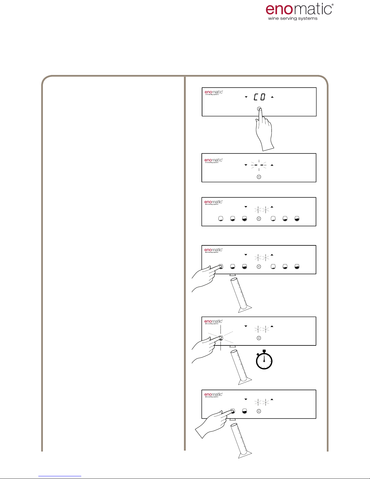
Having entered the "F.4 function"
and having chosen "CO" (para. 27)
press the multifunction button (Z).
Flashing of the display lines con-
rms successful programming of the
setting.
The Dispenser is now in program-
ming mode, indicated by ashing of
the two points on the display.
Place a glass or a graduated cylinder under any dispensing nozzle (S)
and press one of the dose dispensing buttons (V) until the desired volume of liquid is obtained.
If the rst pressing lasts less than
half a second, the dose will not
be perceived and an error will be
reported with rapid ashing of all
the light buttons.
In the next 5 seconds, if the dis-
pensed volume is insufcient, it
is possible to increase it either by
pressing once more or with short
sequential pressings.
After 5 seconds from the last
dosing, the Dispenser will recognise
the dose and will prepare for the
next one. The button relating to the
dose just stored is now switched off.
Repeat the same operation for the 2
remaining buttons.
< 5”
28. CO (copy) DOSE PROGRAMMING
USE AND OPERATION
Before following the instructions described below, it is advisable to read paragraph
26 and 27.
Page 33
eno one 2/r - user manual
REV.05
33
Having programmed all three doses, the Dispenser automatically copies
the doses set into the adjacent dispensing unit and then places itself in
operating mode.
Before inserting a bottle of wine it is advisable to perform the pipe emptying procedure (para. 46).
Page 34
eno one 2/r - user manual
REV.05
34
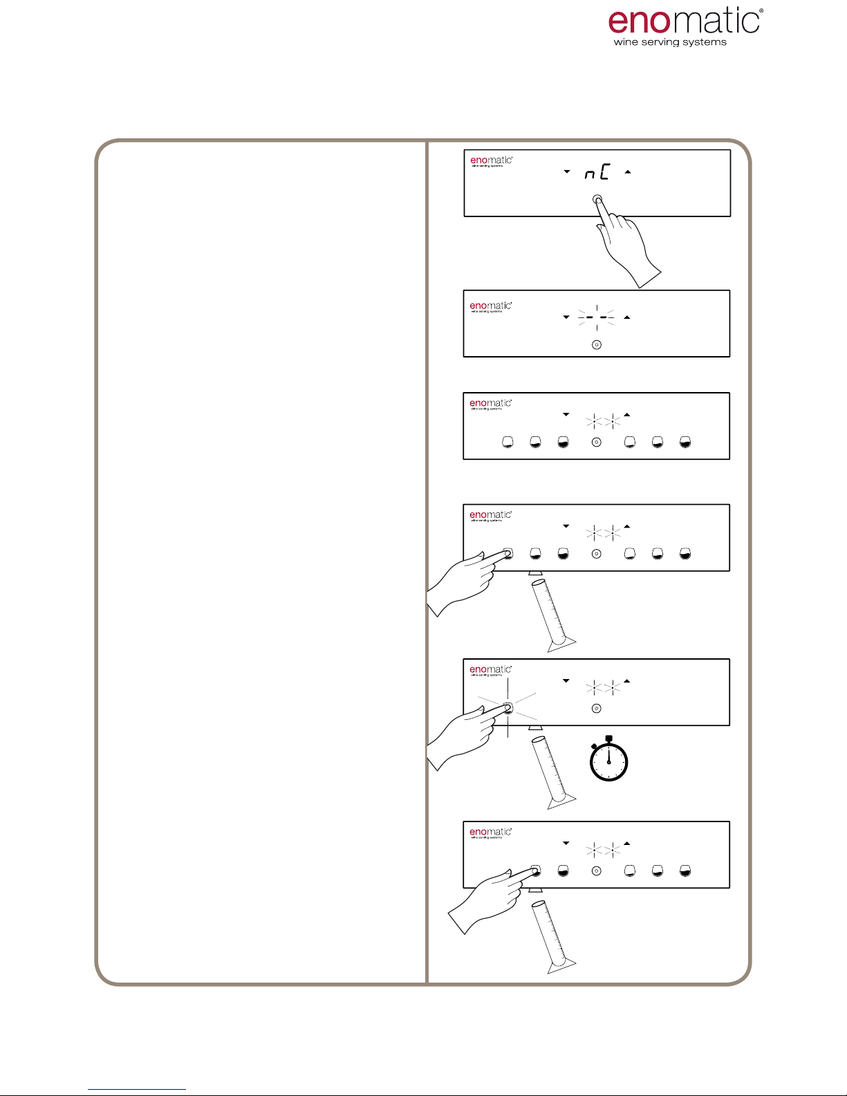
29. nC (not copy) DOSE PROGRAMMING
Having entered the "F.4 function" and
having chosen "nC" (para. 27) press
the multifunction button (Z).
Flashing of the display lines conrms
successful programming of the setting.
The Dispenser is now awaiting
programming, dened by ashing of
the two points on the display.
Place a glass or a graduated cylinder
under any dispensing nozzle and
press one of the dose dispensing
buttons (V) until the desired volume
of liquid is obtained.
If the rst pressing lasts less than
half a second, the dose will not be
perceived and an error will be re-
ported with rapid ashing of all the
light buttons.
In the next 5 seconds, if the dis-
pensed volume is insufcient, it
is possible to increase it either by
pressing once more or with short sequential pressings.
After 5 seconds from the last
dosing, the Dispenser will recognise
the dose and will prepare for the next
one. The button relating to the dose
just stored is now switched off.
Repeat the same operation for the
5 remaining buttons. Having programmed all the doses, the Dispenser places itself automatically in operating mode.
< 5”
< 5”
USE AND OPERATION
Before following the instructions described below, it is advisable to read paragraph
26 and 27.
Before inserting a bottle of wine it is advisable to perform the pipe emptying procedure (para. 46).
Page 35
eno one 2/r - user manual
REV.05
35
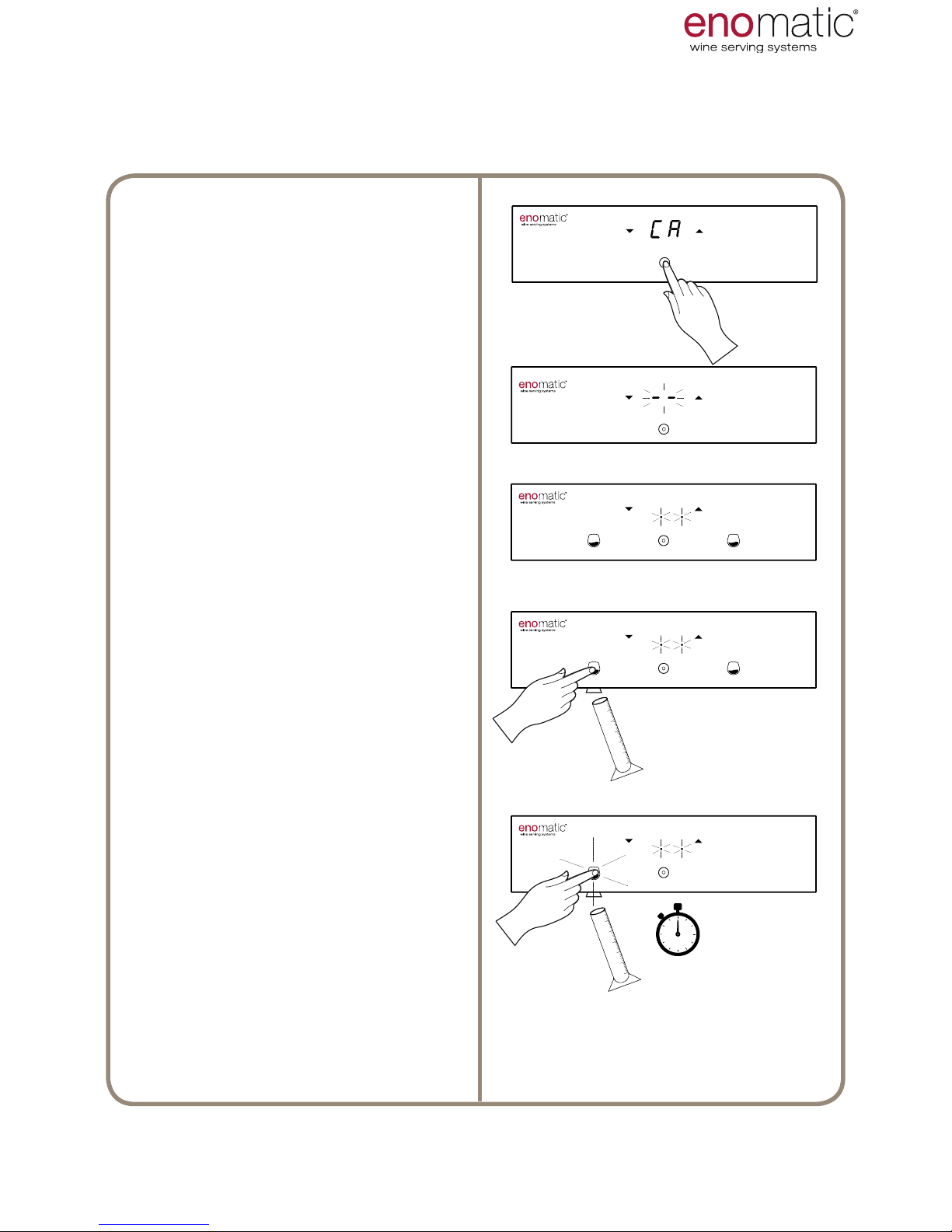
30. CA (copy all) DOSE PROGRAMMING
Having entered function "F.4 " and
having chosen "CA" (para. 27) press
the multifunction button (Z).
Flashing of the display lines conrms
successful programming of the setting.
The Dispenser is awaiting
programming, dened by ashing of
the two points on the display.
Place a glass or a graduated cylinder under the dispensing nozzle and
press one of the medium dose dispensing buttons (V2) until the desired volume of liquid is obtained.
If the rst pressing lasts less than
half a second, the dose will not be
perceived and an error will be re-
ported with rapid ashing
of all the light buttons.
In the next 5 seconds, if the dis-
pensed volume is insufcient, it
is possible to increase it either by
pressing once more or with short sequential pressings.
Having programmed the one dose,
the Dispenser automatically copies it
into the adjacent tap and then places
itself in the operating mode.
< 5”
USE AND OPERATION
Before following the instructions described below, it is advisable to read paragraph
26 and 27.
Before inserting a bottle of wine it is advisable to perform the pipe emptying procedure (para. 46).
Page 36
eno one 2/r - user manual
REV.05
36
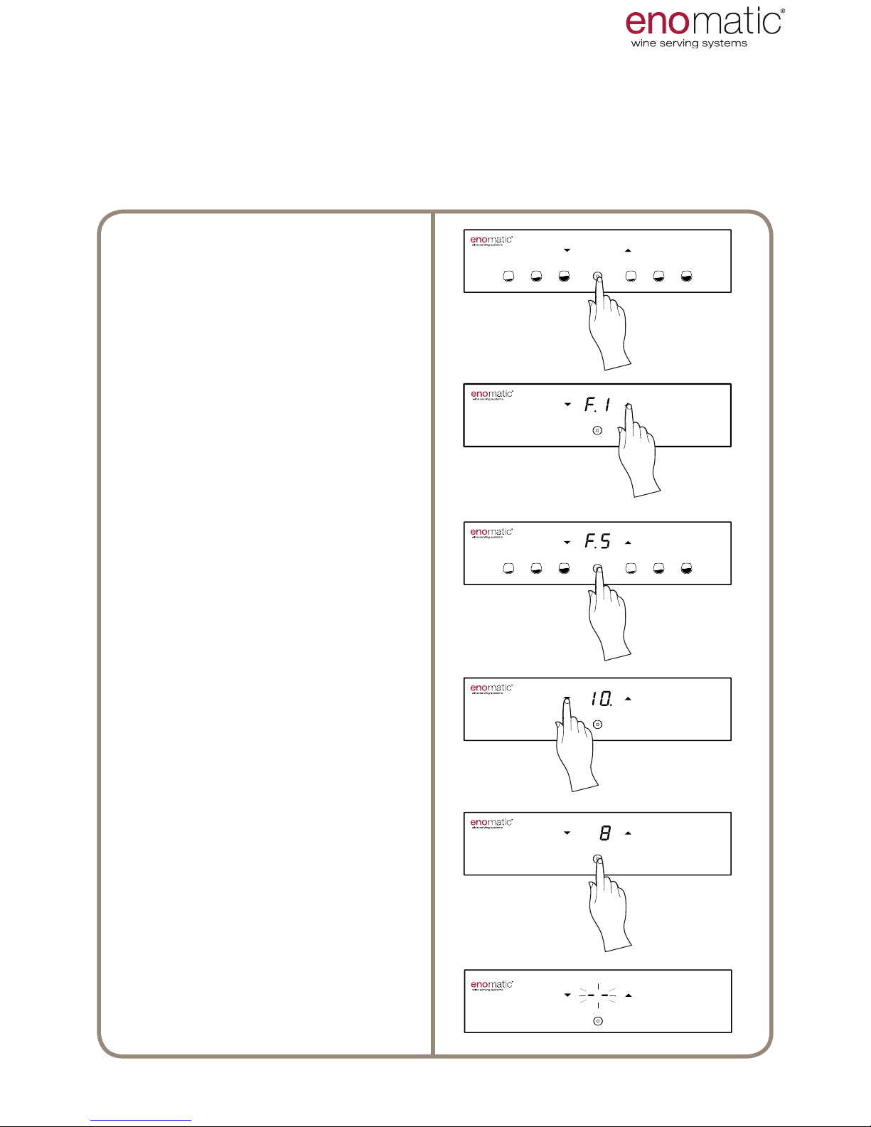
31. F.5 LED INTENSITY SETTING [default value 10]
The Dispenser has an LED strip (R) which illuminates the bottles. The LED light
comes on together with the Dispenser. The intensity of light can be set from a value
of "1" to a "maximum" of “10” or can be set in mode “OF” = OFF
to "10" = Maximum brightness.
From the operating state press the
multifunction button(Z) for 3 seconds
and release it as soon as the letters
"F1" are displayed.
Scroll with the arrow buttons (X, Y)
to select the function “F.5”
Press the multifunction button (Z) to
access the function chosen.
The Dispenser will display the current setting highlighting it with a point
“ .”
Scroll with the arrow buttons to
select the desired setting between
“1÷10/OF”.
Press the conrmation button (Z) to
save the setting.
Flashing of the display lines conrms
successful programming of the setting.
3’’
USE AND OPERATION
Page 37
eno one 2/r - user manual
REV.05
37
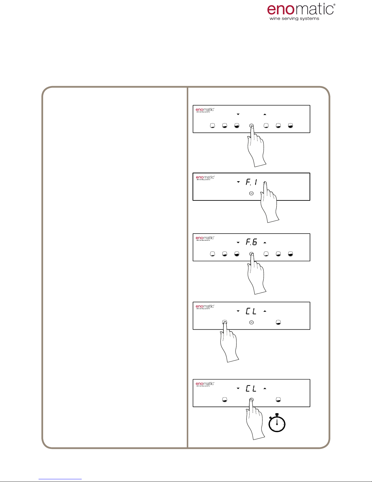
32. F.6 WASHING AND SANITISING CL
From the operating state press the
multifunction button(Z) for 3 seconds
and release it as soon as the letters
"F1" are displayed.
Scroll with the arrow buttons (X, Y) to
select the function “F.6”
Press the multifunction button (Z) to
access the function chosen.
The Dispenser will display the function of washing/sanitising "CL"
(Cleaning).For the procedures to be
performed, see para. 44.
During this function refrigeration is
switched off to limit energy consumption.
The Dispenser, from this function,
does not place itself automatically
in operating mode.
Once the procedure is nished, to return to the operating mode press the
multifunction button (Z) for more than
3 seconds.
3’’
> 3”
With this function it is possible to access the washing and sanitising program of
the dispensing units. Enomatic recommends washing according to the dispenser
unit scheduled maintenance table (para. 49) and every time that the message "cL"
(para. 36) appears on the display.
USE AND OPERATION
Page 38
eno one 2/r - user manual
REV.05
38
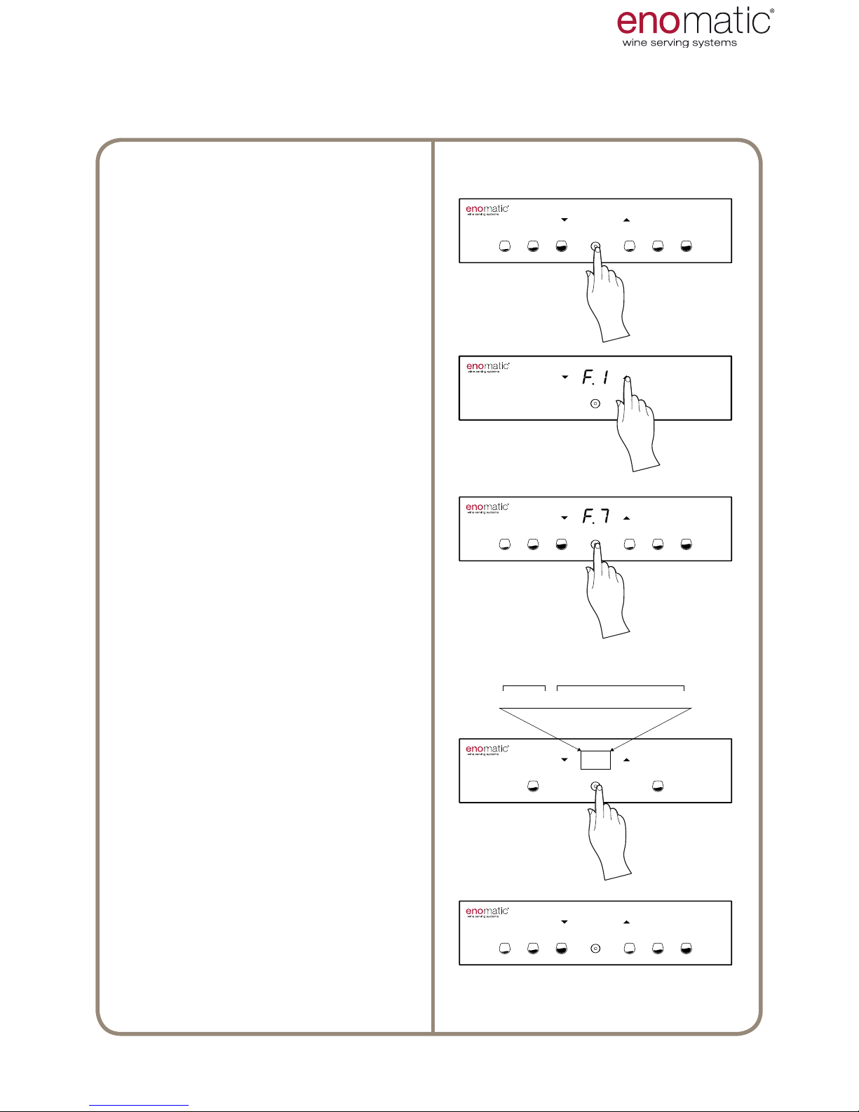
33. F7 DISPENSER VERSION
From the operating state press the
multifunction button(Z) for 3 seconds
and release it as soon as the letters
"F1" are displayed.
Scroll with the arrow buttons (X, Y)
to select the function “F.7”
Press the multifunction button (Z) to
access the function chosen.
The Dispenser will alternatively display a series of numbers and letters
that dene the hardware installed (1)
and the rmware version loaded (2).
Once the display view is completed,
the Dispenser automatically returns
to the operating mode.
3’’
H--02--F--01--00--01--03
1 2
This function displays the hardware version of the dispenser and of the software
installed.
USE AND OPERATION
Page 39
eno one 2/r - user manual
REV.05
39
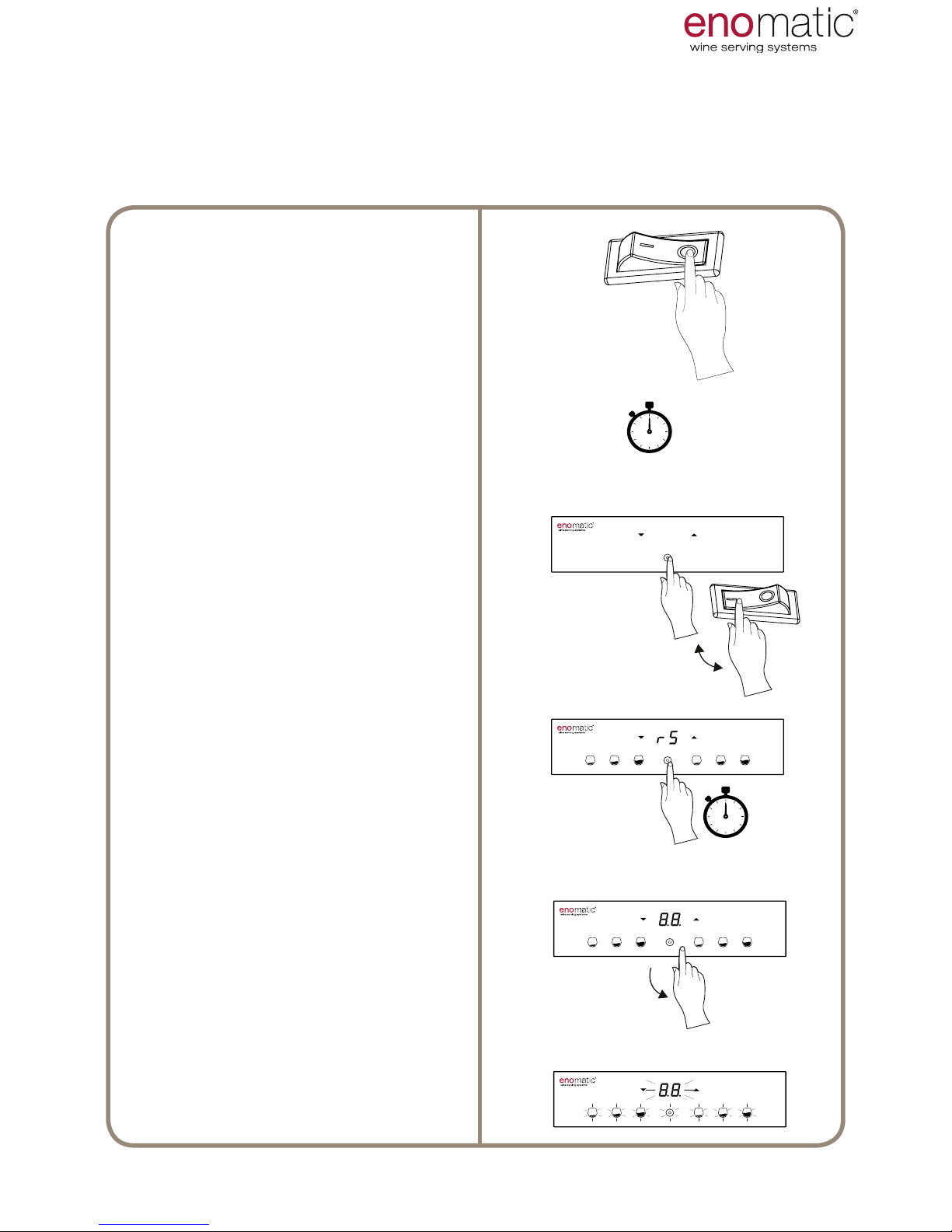
34. DEFAULT RESET
Turn the main switch (L) into position
"O" = OFF and wait at least 10 seconds.
Press and hold the multifunction button (Z) and at the same time turn on
the main switch (L).
...hold down the multifunction button (Z)...
The display will show the word "rS"
(Reset)
...hold down the multifunction button (Z)...
Release the multifunction button as
soon as the display shows "8.8."
Flashing of the display and of the
keyboard icons conrms successful
default settings reset after which the
Dispenser will automatically change
to operating mode.
> 10”
3”
If necessary, it is possible to reset all the settings to the defaults values. The default
values are shown in square brackets
[...]
next to the title of each paragraph of the
function.
USE AND OPERATION
Page 40
eno one 2/r - user manual
REV.05
40
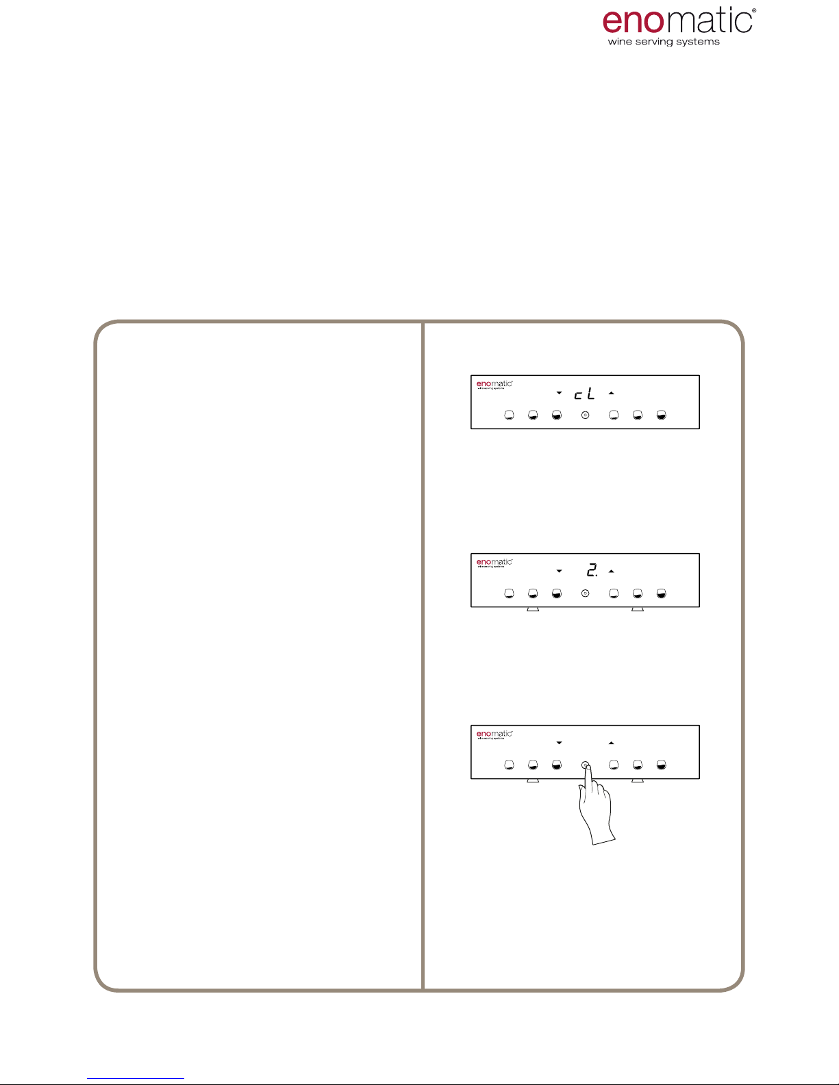
35. WARNINGS
The Dispenser shows the letters "cL",
followed by the number of the dispenser unit that needs cleaning.
The example of the image to the side
indicates that it is necessary to clean
dispenser unit no. 2
Where cleaning will not be performed
immediately, it is possible to hide the
alert by pressing
the multifunction button (Z).
If the alert persists it will be displayed
again after 24 hours or upon each
subsequent access to the functions
menu.
1 2
1 2
All the warnings are indicated on the display with dedicated abbreviations. A warning does not interrupt the normal functioning and may be temporarily hidden for
24h. Having resolved the problem, the warning disappears automatically from
memory. If several warnings are present, they will be displayed in succession for
approximately 2 seconds each.
This warning appears in the display with the letters “cL” (cleaning) when it is necessary to clean the dispensing unit (para. 44).
36. WARNING WASHING DISPENSER UNIT cL
USE AND OPERATION
Page 41
eno one 2/r - user manual
REV.05
41
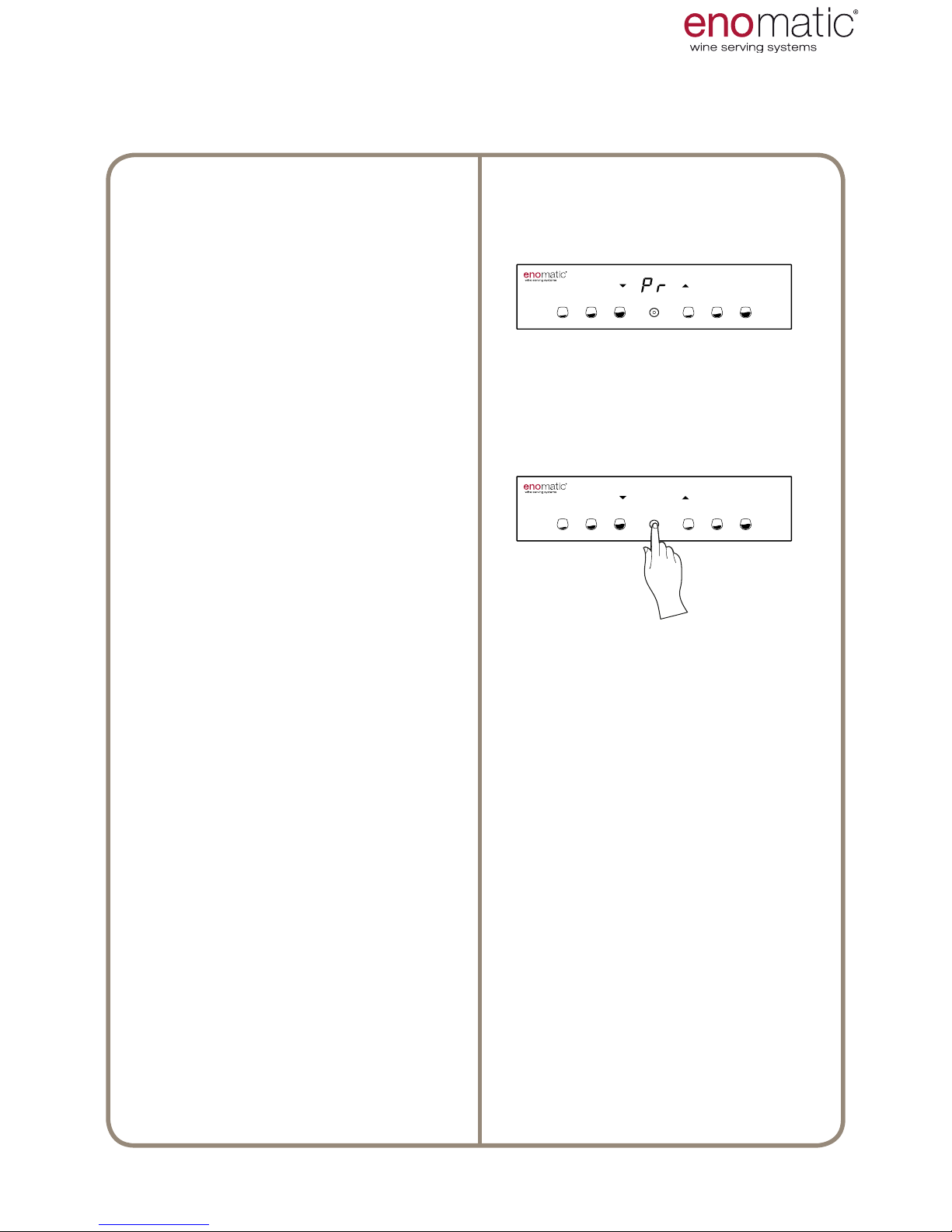
37. FAULT ALERT PROBE Pr
The dispenser shows the letters "Pr"
and
immediately stops refrigeration of
the bottle compartment to avoid
damage to the thermoelectric refrigeration system (O). In this case,
contact an authorised Service
Centre or Retailer.
To hide the alert, press the multifunction button (Z). If the fault persists it
will be displayed again after 24 hours
or upon each subsequent access to
the functions menu.
In case of damage to the refrigeration system or to the probe, while
waiting for the intervention of a
Technician, it is possible to continue to use the Dispenser by setting
the temperature to "OF" (para .23),
thus in ambient temperature mode.
USE AND OPERATION
This alert is displayed with the letters "Pr" when the dispenser detects a refrigeration control device temperature probe (Q) fault.
Page 42
eno one 2/r - user manual
REV.05
42
38. CLEANING THE DISPENSER
Before starting to clean the Dispenser carefully read the warnings
section (para.1) and the scheduled maintenance frequencies table
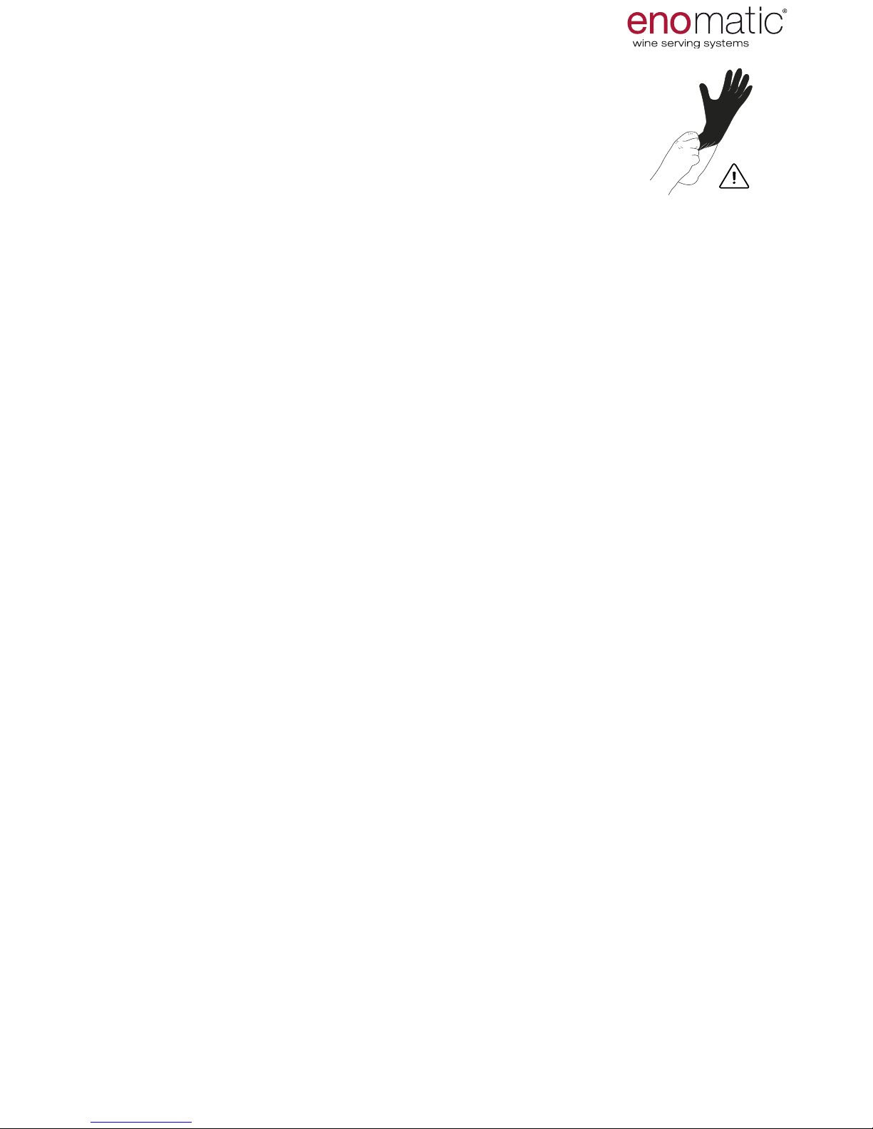
(para. 48). The use of gloves is recommended for performing all the
cleaning operations.
39. CLEANING OF THE EXTERNAL PARTS
During this cleaning operation always disconnect the power cord. Gently use a
soft, non-abrasive cloth, slightly dampened with warm water and wipe all the surfaces - front/side/rear/top. Avoid cleaning the command keyboard and the display
(A) before having read the relevant paragraph (para.40). Finally, dry thoroughly with
a dry cloth.
40. CLEANING THE COMMAND KEYBOARD AND DISPLAY
During this cleaning operation always disconnect the power cord.
Use a soft, dry and non-abrasive cloth as the keyboard is sensitive to moisture.
While cleaning exert light pressure
to avoid the keyboard being irreparably damaged.
MAINTENANCE
41. CLEANING THE DRIP GRILL WITH
TRAY AND REAR VENTILATION GRILL
A few drops of wine always fall from the dispensing nozzle into the relevant drip
grill with tray (C). To remove the tray, open the door (B) and lift the drip grill keep-
ing it in a horizontal position. Close the door again. Then drain off the liquid from
the tray and clean it using a non-abrasive sponge with water at a maximum temperature of 40°C/104°F and possibly a mild detergent. Finally, rinse thoroughly with
water, dry completely and replace in position.
Do not wash the tray in a dishwasher.
Do not use the Dispenser without the tray. Always check that there is no liquid
or condensate inside the Dispenser under the drip tray. In this case, disconnect the Dispenser from the power supply network, gently clean with a soft,
non-abrasive, cloth slightly dampened with warm water and possibly a mild detergent. Finally, dry thoroughly with a dry cloth.
Also pay special attention to the removal of dust and any other residue from the
rear aeration grills (D) to allow correct air circulation, which is essential for good
operation and therefore to ensure improved longevity of the thermoelectric refriger-
ation system (O).
Never use paper or material that could scratch.
Where cleaning the grills described above (C, D) is not sufcient to restore
proper functioning of the refrigeration system, it is advisable to contact an authorised Technician or the Retailer to perform complete and precise cleaning
of the refrigeration system (O).
Page 43
eno one 2/r - user manual
REV.05
43
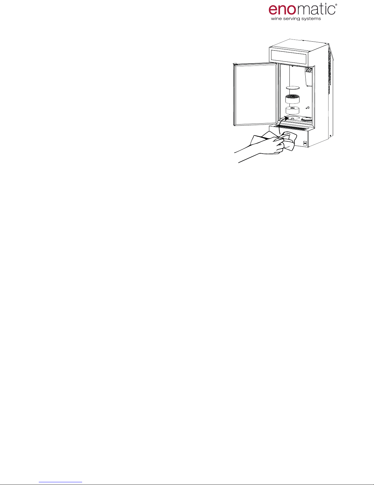
42. CLEANING OF THE BOTTLE COMPARTMENT
This cleaning operation must be take place with
cooling mode deactivated, thus setting the temperature to "OF" (para. 23), or by setting the switch (L)
in position "0" = OFF, or during the bottle loading
function “F.1” (para. 20).
The bottle compartment (P) and the space below
the piston for lifting the bottles (T) must always
be clean to avoid the formation of unpleasant
odours and/or moulds, in particular after acci-
dental liquid spills. Use a soft, non-abrasive cloth,
slightly dampened with warm water and possibly
a mild detergent. Finally, dry thoroughly with a dry
cloth. Wipe away any moisture that forms inside
the compartment and on the bottles every time
the door is opening, including during a bottle
change.
T3
T4
T2
MAINTENANCE
WASHING
The dispenser unit must be washed periodically following the scheduled maintenance frequencies table (para. 48).
1. Enter the functions menu and select the washing and sanitising function “F. 6 ”
(para. 32)
2. Remove the bottle of wine from the Dispenser.
3. Fill an empty bottle with a special solution for washing (para. 45)
4. Check that the rubber straw is inserted on the plug tap (N).
5. Insert the bottle, with the solution into the Dispenser.
6. Place a container under the dispensing nozzle (S), then dispense all the liquid
present in the bottle in 5-6 times, pressing the one active button (V2) and waiting
a few tens of seconds between one dispensing event and the next, so that the
solution cleans the dispensing unit.
7. Remove the bottle and perform the procedure emptying the ducts as described
in para.46, in order to remove the washing solution.
8. Insert a bottle lled only with drinking water and then rinse, dispensing until
complete emptying of the same as described in step 6.
9. Remove the bottle and repeat the duct emptying procedure (para.46).
10. Once the procedure is nished, to return to the operating mode press the
multifunction button (Z) for more than 3 seconds.
Do not use solutions with characteristics other than those described in this
manual for cleaning the dispenser unit.
Disconnect the straw from the plug tap, rinse inside and outside under a stream
of water at a maximum temperature of 40°C ( 104°F) paying particular attention
to cleaning the lter that is located at one of the two ends. If the straw is still dirty,
soak it in water for a few minutes. If it is still not sufciently clean, soak it in a washing solution (para.45) for a few minutes, then rinse under a jet of water with the
above mentioned characteristics. Finally shake vigorously to expel the remaining
liquid from the inside and allow to dry in a clean place.
Do not wash the straw in the dishwasher and do not use dishwasher detergent.
43. CLEANING OF THE RUBBER STRAW
44. WASHING AND SANITATION OF THE DISPENSER UNIT
Page 44
eno one 2/r - user manual
REV.05
44
46. DRAINAGE OF THE DUCTS
Emptying of the ducts is an operation that allows expulsion of the
wine residues from the inside of the pipes of the dispenser units.
This is NECESSARY in the following cases:
• when the removal of a bottle does not allow the immediate insertion of another.
In this case also clean the dispenser unit (para. 44)
• before a period of non-use (para. 50)
The following are OPTIONAL in the following three cases:
• when a wine is replaced with another different one in order to avoid mixings of
avour
• when programming of the dose was performed using water
• when the dispenser unit washing/sanitising procedure has been performed
(para. 44)
SANITISING
The dispenser unit must be periodically sanitised following the scheduled maintenance frequencies table (para.49). Perform the same steps for the dispenser unit
washing procedure but using the appropriate solution for sanitising (para. 45). Each
sanitisation must be followed by washing.
Only use the cleaning products provided by the Authorised Retailer
or prepared carefully following the instructions given in this paragraph. During the
preparation of the washing solutions to strictly follow the instructions given in
the safety data sheets of the products used.
45. SOLUTION FOR WASHING AND SANITISATION OF THE
DISPENSER UNIT
Method:
1. Remove the straw from the plug tap (N).
2. Insert an empty bottle in the bottle compartment on the dispenser unit to be
cleaned.
3. Place a glass under the dispenser nozzle (S) and press the medium dose button
(V2). In the case of free dispensing mode "FE" (para. 25) hold for at least 5 seconds.
4.
Wait a few seconds after the end of the dispensing for complete draining of the
pipe.
5. Remove the empty bottle.
MAINTENANCE
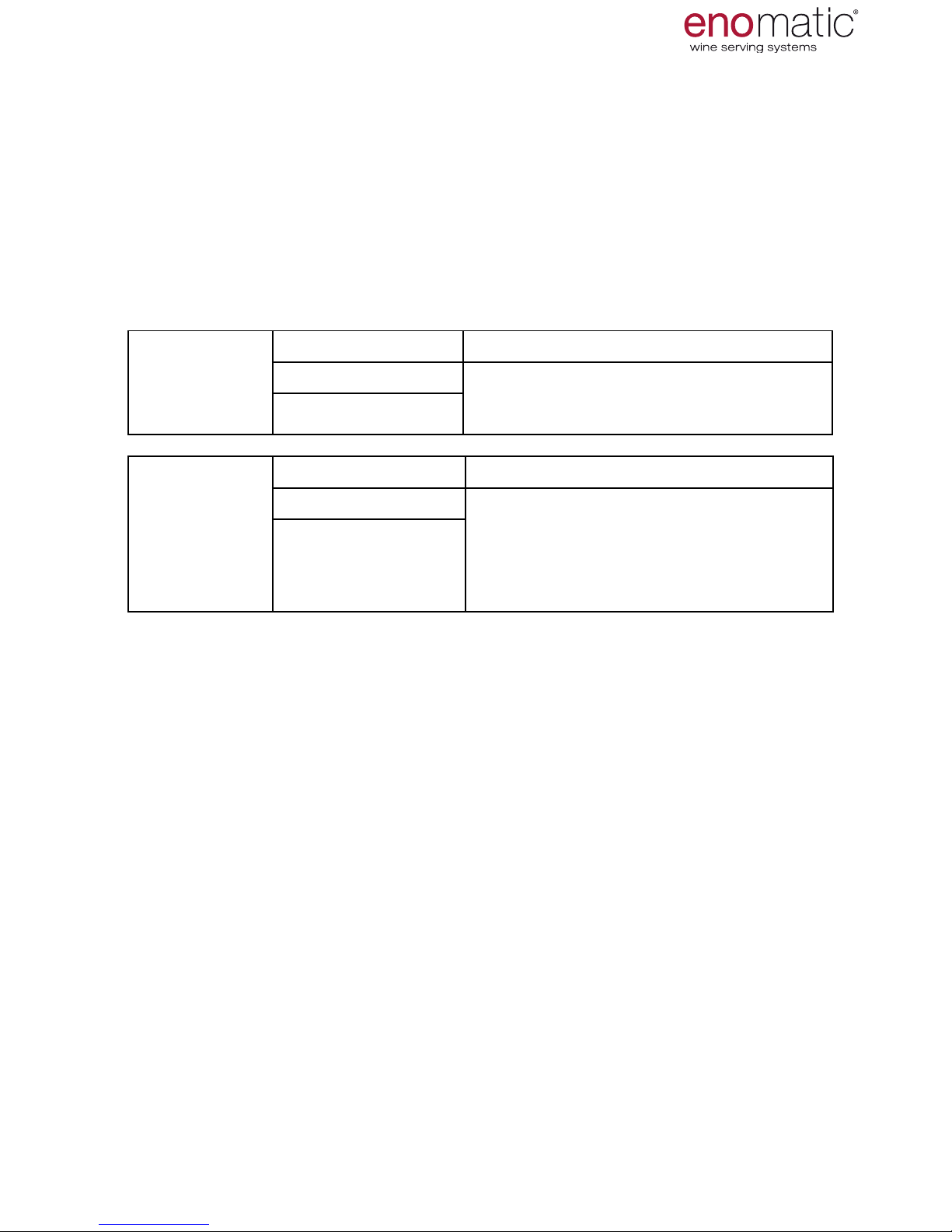
SOLUTON
FOR WASHING OF THE
COMPONENTS PREPARATION METOD
Drinking water Dissolve 15gr (0,53 oz) of citric acid
in 750ml (26.4 oz) of warm water, no
more than 30°C (86°F)
Citric acid (E330)
SOLUTION
FOR SANITISING
COMPONENTS PREPARATION METHOD
Drinking water Dilute 15gr (0,53 oz) of chlorine-ac-
tive detergent in 750ml (26.4 oz) of
cold water, no more than 20°C (68°F)
Disinfectant detergent
solution with a maximum of 4.5% chlorine-active component
Page 45
eno one 2/r - user manual
REV.05
45
47. INFORMATION ON MAINTENANCE
To keep the dispenser in conditions of maximum efciency it is necessary to
carry out the maintenance recommended by the manufacturer
Good maintenance will facilitate better performance and extend
operating duration.
48. GENERAL SCHEDULED MAINTENANCE
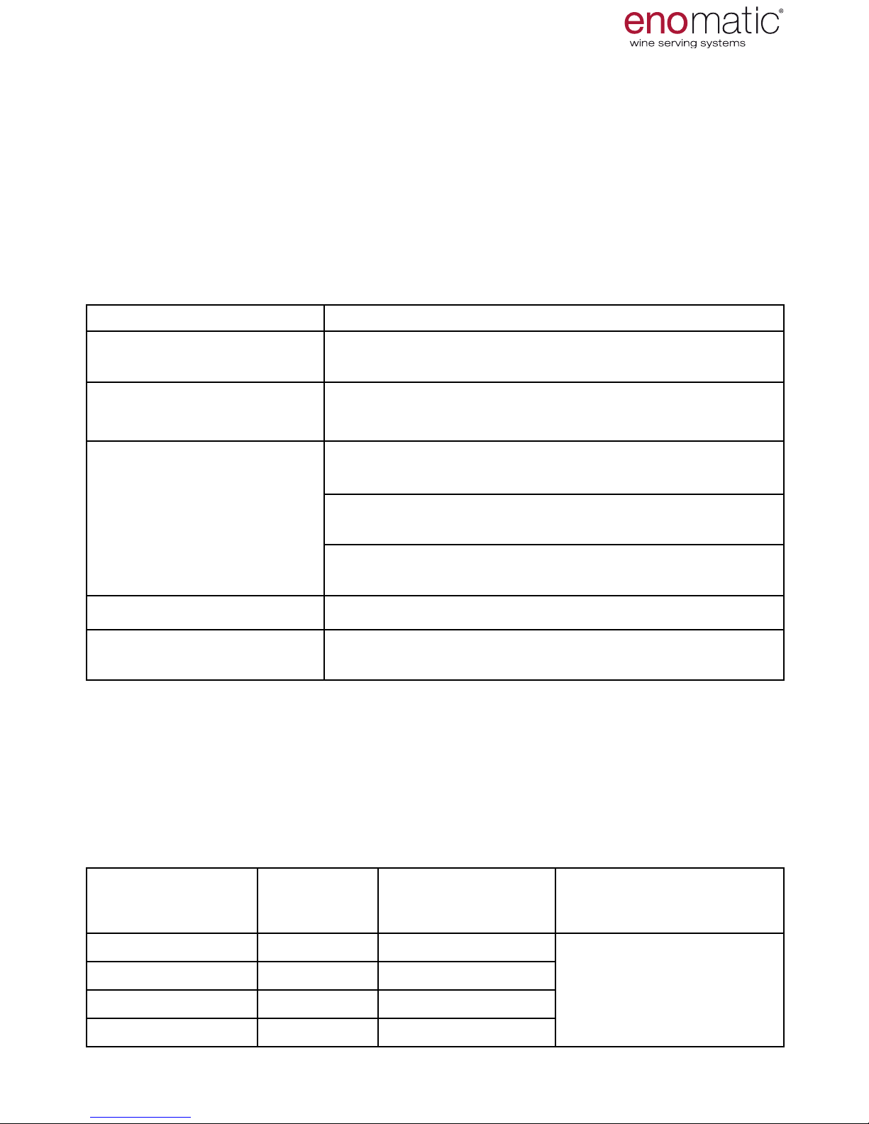
FREQUENCIES TABLE
FREQUENCY ACTION
Every
2 weeks/1 month
Cleaning of the rubber straw (para. 43)
Every time the message
"cL" appears
Washing of the Dispenser unit (para. 44)
Every day /
when necessary
Cleaning of the drip grill with tray and rear aeration
vents (para. 41)
Cleaning the external parts (para. 39) and cleaning the
bottle compartment (para.42)
Cleaning the command keyboard and display (para.
40)
Every month Washing of the Dispenser unit (para. 44)
Every six months Sanitising the dispenser unit (par.44) and then washing
of the dispenser unit
MAINTENANCE
IT IS
advisable to follow the actions in the following table with the specied fre-
quency. Avoid performing the operation when the bottle is not completely empty
to
protect the wine from oxidation .
The frequency of washing depends on the type of wine
TYPES OF WINE SUGAR CON-
TENT grams/
litre
NUMBER BOTTLES
DISPENSED 750 ml
ACTION
Dry wine < 9
each 150 approx
Washing of the Dispenser
unit (para. 44)
Sweet wine < 18
each 120 approx
Sweet wine < 45
each 100 approx
Sweet wine > 45
each 30 approx
49. SCHEDULED MAINTENANCE DISPENSER UNIT FREQUENCIES
TABLE BY TYPE OF WINE
It is advisable to follow the actions in the following table with the specied frequency. Avoid performing the operation when the bottle is not completely empty
to pro-
tect the wine from oxidation .
Page 46
eno one 2/r - user manual
REV.05
46
50. PERIOD OF NON-USE
1. Sanitise the dispenser units (para. 44)
2. Empty the ducts (par.46)
3. Disconnect the equipment from the power
supply
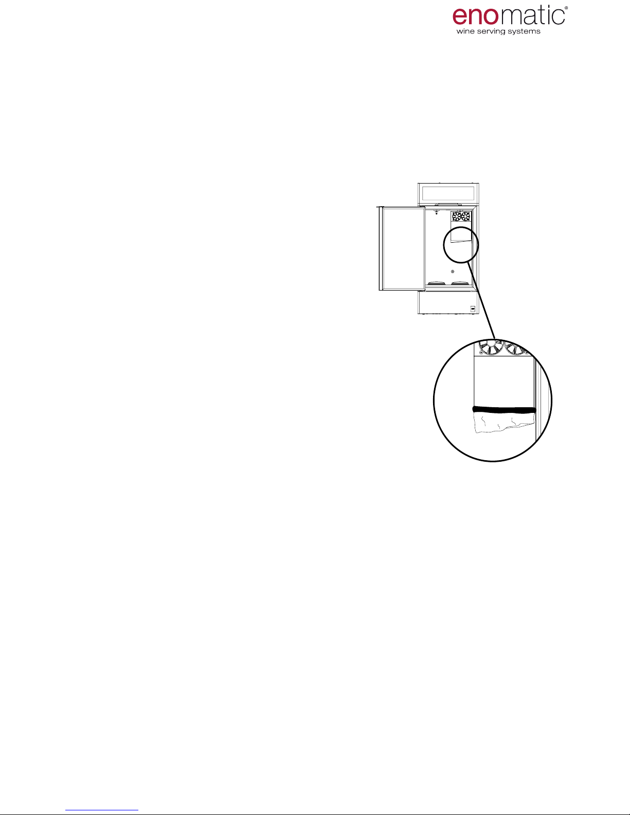
4. Insert into the chute of the condensate drain
(see image to the side) an absorbent cloth that
is easily removable to avoid the condensate
owing into the collection tray. Never use paper or other material that can tear.
5. Clean the rubber straws (para.43).
6. Clean the external parts (para.39)
7. Clean the drip grill with tray (para.41)
8. Clean the bottle compartment (para.42)
9. Clean the door gasket (B)
10. Clean the command keyboard and display
(par.40)
11. Leave the door slightly open (to allow air
circulation)
12. Cover the Dispenser with the appropriate
non-woven fabric bag.
MAINTENANCE
Before and after a period of non-use, perform the cleaning of all the components,
as described below:
Page 47
eno one 2/r - user manual
REV.05
47
51. TROUBLESHOOTING
Any repair work on the mechanical parts and on the electrical system must be performed with electrical voltage removed (with the power cable of the Dispenser disconnected from the mains socket) and only by authorised technicians.
Inattention and/or incorrect performance of the actions indicated in this manual
may cause malfunctions that can be solved by the actual user.
The following information is intended to help identify and correct faults and malfunctions that may occur during use. If the problem persists or is not solved, please
contact the Authorised Service Centre or Retailer.
The list of retailers is available at www.enomatic.com
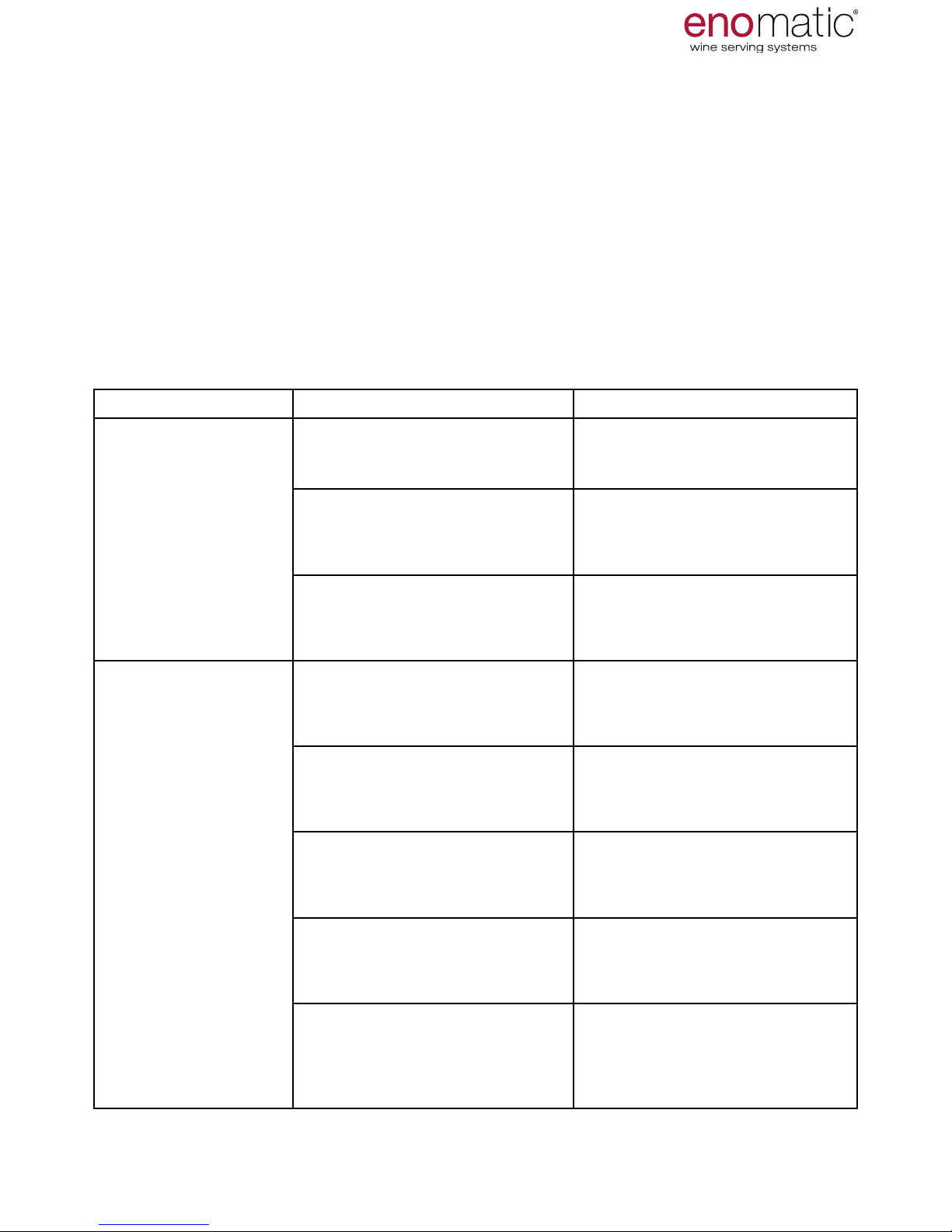
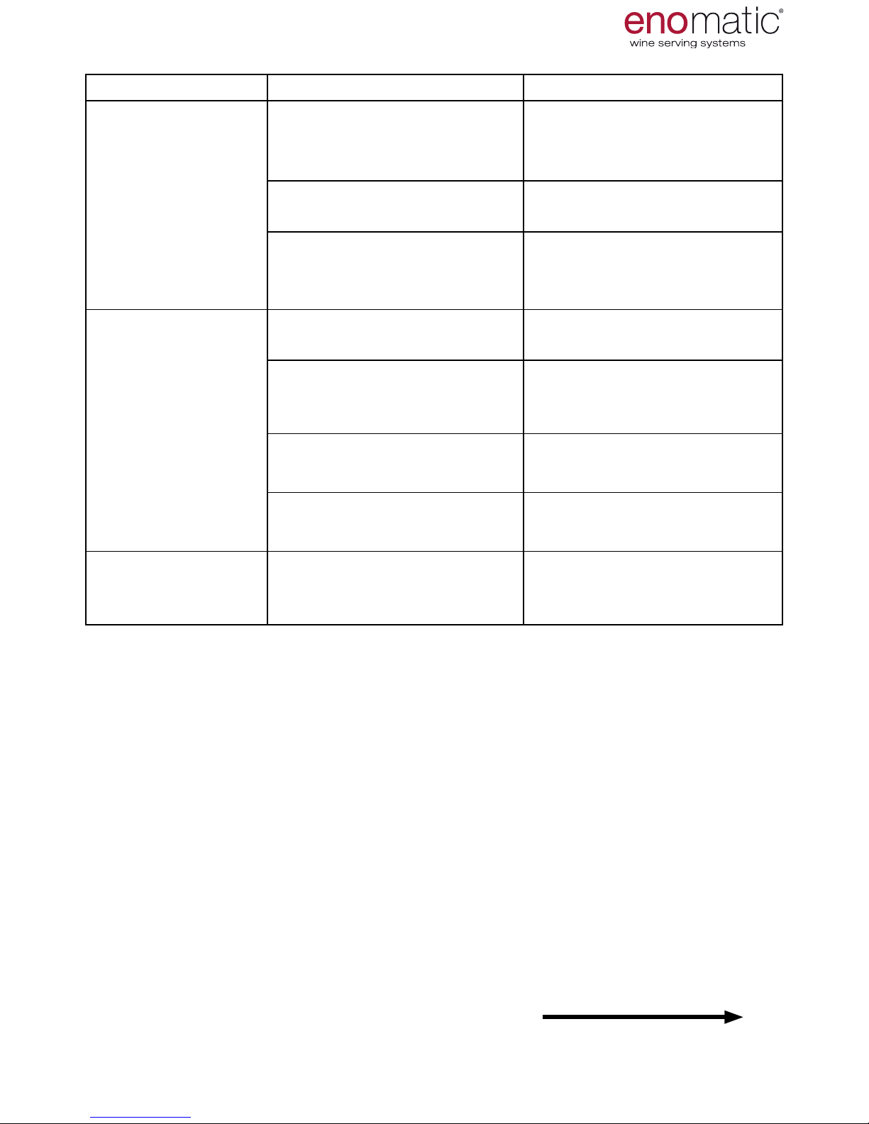
PROBLEM POSSIBLE CAUSE SOLUTION
The dispenser
does not
come on
No voltage on the power
supply network
Restore the power supply
(para.15)
Electrical power not activated
Plug in the power cord and
turn the main switch to the
position "I" = ON (para.16)
Power cable
visibly damaged
Request a new power cable
from the Retailer
The Dispenser
does not sufciently cool
the compartment
Unsuitable ambient condition Position the Dispenser in an
appropriate ambient (para.12)
The installation spaces are
not respected
Restore the correct installation spaces (para.12)
Drip grill and aeration grills
are obstructed by objects or
dirt
Remove any objects or clean
the air grills (para.41)
The door is not properly
closed or is opened
Dry off any condensation on
the bottle compartment and
close the door (para.42)
A high temperature value has
been set or the refrigeration
system has been disabled
(OF)
Change the setting of temperature, according to requirements (para.23)
TROUBLESHOOTING
Page 48
eno one 2/r - user manual
REV.05
48
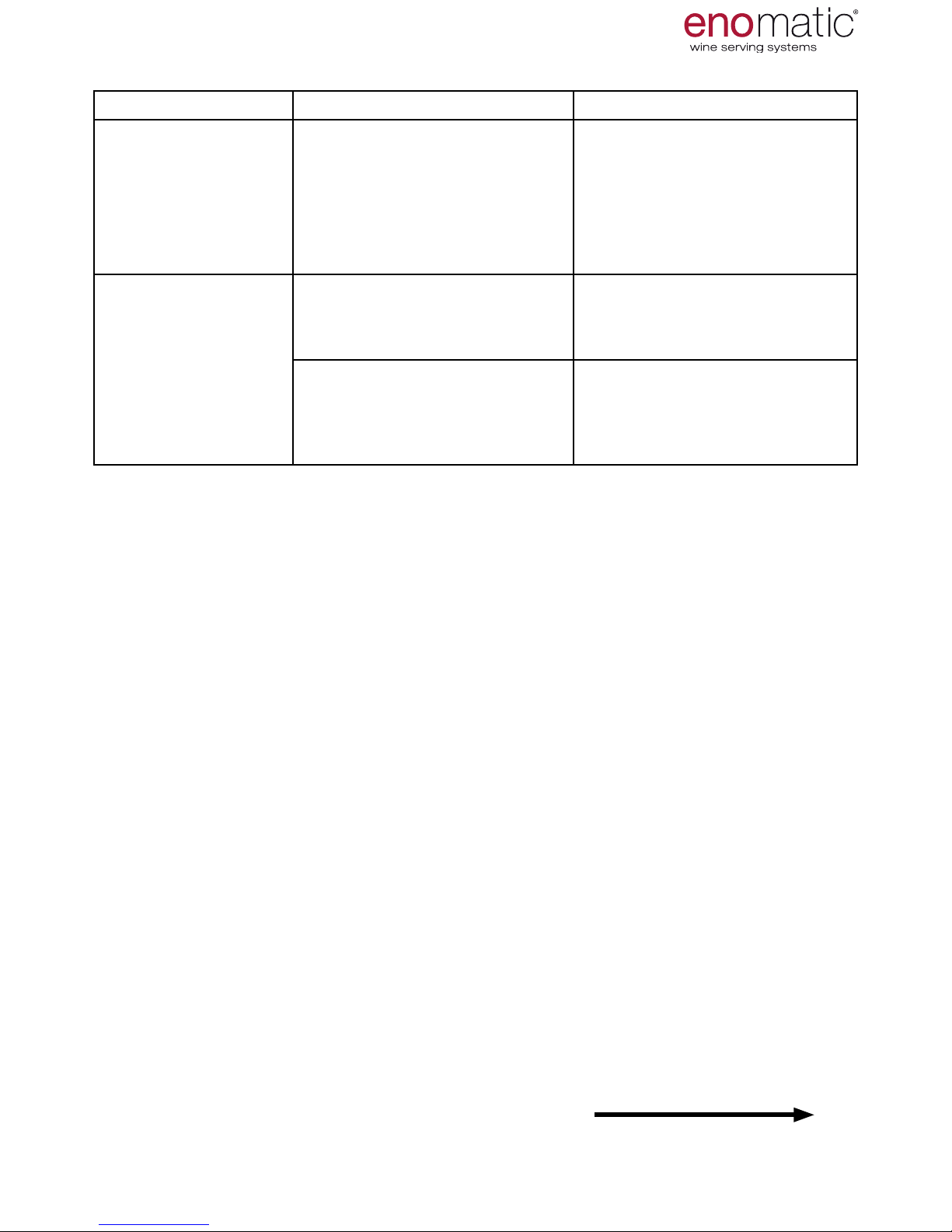
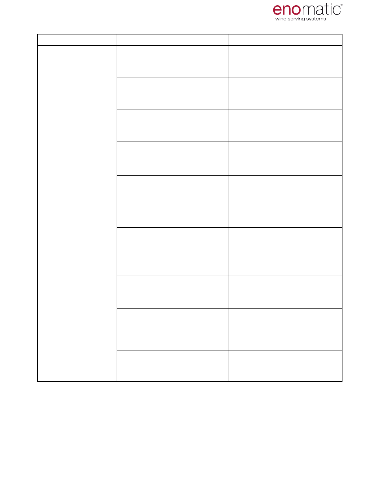
PROBLEM POSSIBLE CAUSE SOLUTION
During normal
operation, some of
the dose buttons
(V) of the dispenser units are disabled.
Free dispenser mode (FE) is
set or programmed (CA)
Select the desired dispensing
mode (para.25)
The piston (T) for
lifting does not remain in the locked
position
It was not sufciently pushed
down
Push the piston down to the
lock position (para.20)
The piston seat is blocked by
foreign objects or the components of the piston are not
correctly positioned
Remove any foreign objects
in the piston seat or position
the components of the piston
correctly.
TROUBLESHOOTING
to be continued
Page 49
eno one 2/r - user manual
REV.05
49
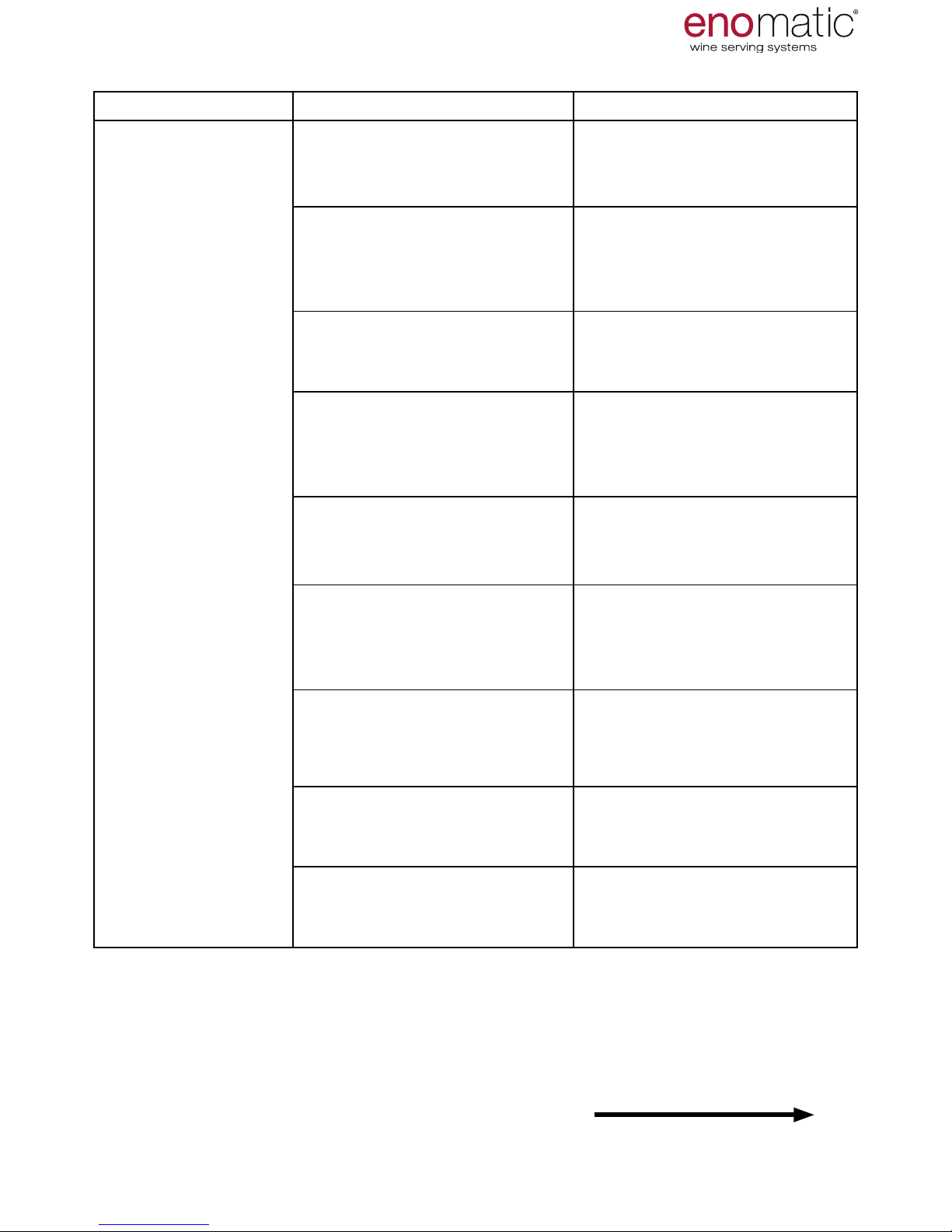
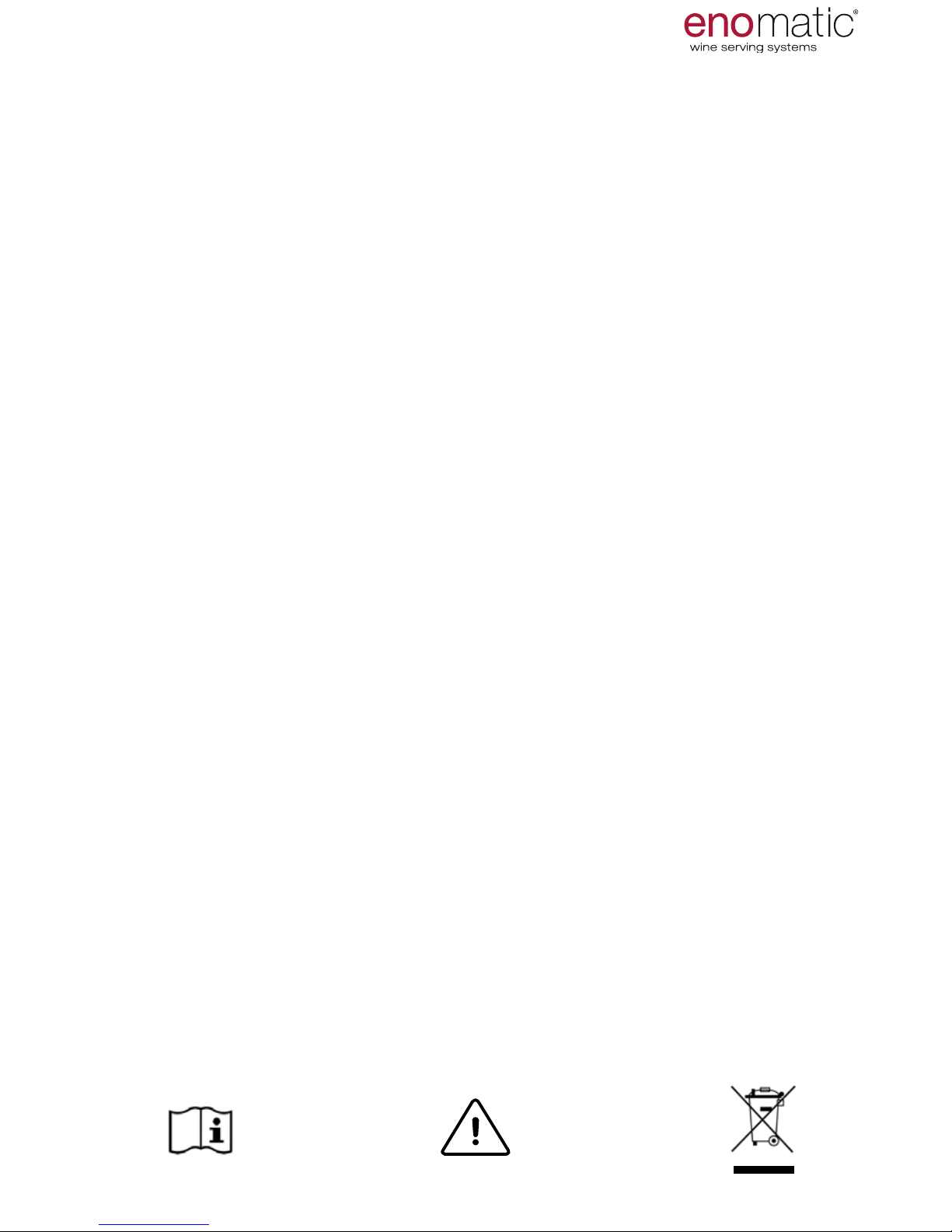
PROBLEM POSSIBLE CAUSE SOLUTION
The wine is not
being dispensed
or it is not being
dispensed in the
amount set
The bottle is not
correctly inserted.
Replace the mouth of the
bottle on the seal of the cap
tap (para.20)
The rubber straw is not properly inserted on plug tap or
is not inserted
Lower the bottle and insert
the straw on the plug tap
unit until it is fully inserted
(para. 20)
The rubber straw is excessively long or short or it is
obstructed
Use a straw of the correct
length, ensuring correct insertion (paras. 18 and 20)
The dispensing gas circuit
is nished or the supply
pressure
is insufcient
Replace the inert gas cylinder
(para.14)
The lter of the rubber straw
is clogged with wine sediment
Clean the rubber straw
(para.43)
Storing of all the doses during the programming phase
was not completed.
Repeat dispensing storage
from all the dose buttons (paras. 28 or 29 or 30)
The dispenser unit is blocked Sanitise the dispenser unit
and then wash the dispenser
unit (para.44)
The seal of the cap tap is
damaged or out of position
Replace the seal with the one
supplied (para. 6). Reposition
the seal
The gas connection pipe
is attened at one or several
points
Request a new connection
pipe from the retailer
TROUBLESHOOTING
to be continued
Page 50
eno one 2/r - user manual
REV.05
50
PROBLEM POSSIBLE CAUSE SOLUTION
The gas cylinder
empties too quickly
Connection of the gas supply
pipes is incorrect
Restore the correct
conditions of the gas supply
(para.14)
The connection pipe is perforated
Request a new gas connection pipe from the retailer
The bottle is not
correctly inserted.
Replace the neck of the bottle on the seal of the cap tap
(para.20)
Excessive presence of condensation on the door (B)
The door is open Close the door
Unsuitable ambient condition Position the Dispenser in
an appropriate ambience
(para.12)
The door seal is out of position
Reposition the seal in the
correct position
Presence of dirt on the door
seal
Clean the door seal
The LED (R) does
not come on
The LED was set in "OF" =
off mode
Change the setting of the
LED intensity, according to
requirement (para.31)
to be continued
TROUBLESHOOTING
Page 51
eno one 2/r - user manual
REV.05
51
PROBLEM POSSIBLE CAUSE SOLUTION
The organoleptic
characteristics of
the wine are altered or unpleasant
A type of gas or gases that
are inadequate for food use
was used
Only use the gases indicated
(para. 14)
The gas being used has expired
Replace the gas cylinder and
empty the pipes (para.46)
The bottle of wine is not inserted correctly
Replace the neck of the bottle on the seal of the cap tap
(para.20)
The bottle of wine inserted
was already altered
Ensure the quality of the bottle of wine before inserting it
in the Dispenser
More than 4 weeks have
elapsed since insertion of the
bottle in the Dispenser
Remove the bottle, wash the
dispenser unit (para.44). It is
advisable to always take note
of the date before inserting a
bottle of wine
Storage temperature of the
wine is too high
Change the setting of temperature, according to requirements (para. 23)
The Dispenser unit has not
been adequately serviced
Sanitise the dispenser unit
and then wash the dispenser
unit (para. 44)
A different type of wine was
inserted without replacing
the straw or without cleaning
the dispenser unit
Clean the dispenser unit and
replace the straw with a clean
or new one.
The straw was not correctly
serviced
Clean the straw or replace it
with a new one
TROUBLESHOOTING
Page 52
eno one 2/r - user manual
REV.05
52
53. DECOMMISSIONING AND DEMOLITION OF THE DISPENSER
-During decommissioning, it is necessary to perform a series of actions to ensure
that the Dispenser is not an obstruction, is not easily accessible and cannot be used.
-During demolition, select all the components according to their chemical character-
istics and arrange for differentiated disposal in compliance with the applicable laws
in force.
-Do not dispose of non-biodegradable products, lubricating oils or non ferrous com-
ponents (rubber, PVC, resins, etc.) into the environment. Carry out their disposal in
compliance with the applicable laws in force.
"According to Art. 26 of Legislative Decree 49/2014: "Implementation of Directive
2012/19/EU on waste electrical and electronic equipment"
The crossed bin symbol on the appliance or on its packaging indicates that the product at the end of its life must be collected separately from other waste.
The user must therefore deliver the equipment at the end of its life to the suitable
separate waste collection centres of electronic and electrical waste.
Adequate separate collection for the future use of the equipment assigned for recycling, treatment and environmentally compatible disposal helps to prevent possible
negative effects on the environment and on human health and promotes recycling
and/or reuse of the materials of which the equipment is composed.
Illegal dumping of the product by the user entails the application of administrative
sanctions provided by the laws in force.
In accordance with ISO-7000 graphical symbols used on the Dispenser
DISPOSAL
52. INFORMATION ON REPLACEMENTS COMPONENTS
• Before carrying out any intervention of replacement, turn off the gas supply
valve, switch off the power supply of the Dispenser and prevent access to all
devices that could, if activated cause unexpected danger conditions resulting in
damage to the health and safety of persons.
• Enable all the required safety devices, if provided, and assess whether it is nec-
essary to adequately inform staff and particularly those operating nearby.
• If it is ever necessary to replace worn parts, use only original spare parts.
• Do not perform interventions that could modify the operating characteristics and
safety requirements of the Dispenser and not replace components with non-original spare parts without the manufacturer's prior written consent.
Page 53
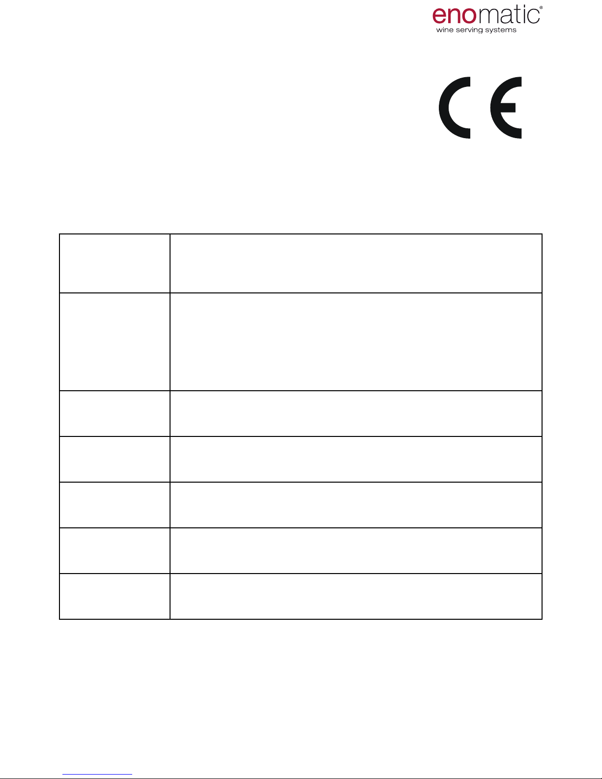
eno one 2/r - user manual
REV.05
53
Enomatic S.r.l.
Via di Meleto,1 int.19
50027 Strada in Chianti (FI)
Italy
declares under its responsibility that the appliance:
AUTOMATIC DISPENSER FOR WINES, model: Eno one 2/r
to which this declaration refers, is in conformity with the following legislation:
IEC EN 60335-1:
2012 (Five Edition)
A11: 2014
Safety of electrical equipment for household and similar use –
Safety – Part 1: Generic standards.
IEC EN 603352-75:2004 (Sec
ond Edition)
+ A1:2005 +
A2:2008 +
A11:2006
A12:2010
Safety of electrical equipment for household and similar use –
Safety – Part 2: Particular requirements for commercial distrib
-
utors and for automatic appliances for sale.
IEC EN 603352-24 :2010
Household and similar electrical appliances - Safety - Part
2-24: Particular requirements for refrigerating appliances, icecream appliances and ice makers.
EN 55014-1:2006
+ A1:2009 +
A2:2011
Electromagnetic compatibility – Requirements for household
appliances, electric tools and similar apparatus – Part 1: Emis
-
sion – Product family standard.
EN 61000-32:2014
Electromagnetic compatibility (EMC) – Part 3-2: Limits - Limits
for harmonic current emissions (equipment input current ≤ 16 A
per phase).
EN 61000-33:2013
Electromagnetic compatibility (EMC) – Part 3-3: Limits - Limita
-
tion of voltage uctuations and ickering in low voltage supply
systems for equipment with rated current ≤ 16 A.
EN 55014-2:1997
+ A1:2001 +
A2:2008
Electromagnetic compatibility – Requirements for household
appliances, electric tools and similar apparatus – Part 2: Immu
-
nity –Product family standard.
DECLARATION OF EC CONFORMITY
54. DECLARATION OF EC CONFORMITY
Page 54
eno one 2/r - user manual
REV.05
54
and therefore meets the essential requirements of the Directives:
- Low Voltage Directive 2006/95/EC (Directive regarding the approximation of the
laws of Member States relating to electrical equipment designed for use within certain voltage limits).
- Electromagnetic Compatibility Directive 2004/108/CE
(Directive on the approximation of the laws of Member States relating to electromagnetic compatibility).
Date of issue
2016
Name and signature of the authorised person
President and CEO
Lorenzo Bencistà Falorni
Enomatic s.r.l.
Via di Meleto,1 int.19
50027 Strada in Chianti (FI) - Italy
VAT No. 01066310523
DECLARATION OF EC CONFORMITY
Page 55

eno one 2/r - user manual
REV.05
55
55. GUARANTEE OF ENOMATIC PRODUCTS
Terms and conditions of the warranty provided by the manufacturer Enomatic S.r.l:
Enomatic guarantees the material supplied for 24 months from the date shown on
the invoice (invoice or receipt with packing slip), showing the details of the installed
products.
• The warranty period for this machine is twenty-four (24) months from the date
shown on the invoice
• The duration of the warranty for the mechanical, electrical and electronic parts of
equipment is twenty-four (24) months from the date shown on the invoice
• Interventions carried out during the warranty period in no way extend the warranty
period of the machine except for the part replaced during the intervention.
The warranty covers the free repair or replacement of parts recognised as defective
from manufacturing with verication and judgement of these by
Enomatic s.r.l.
Enomatic offers a warranty directly or through its Repair centres. Enomatic reserves
the right to refuse the warranty if the system is not made up entirely of components
supplied by Enomatic.
It is understood that the warranty is subject to compliance with performance speci
cations of the products indicated by Enomatic.
The warranty will not operate if Enomatic S.r.l. ascertains on the machinery unauthorised alterations or interventions or tampering of any kind.
The warranty does not include:
• Faults or damage caused by transportation.
• Faults or damage caused by defects in the electrical system and/or from carelessness, negligence, inadequacy of the system for the use for which it is intended and
in any case from abnormal use.
• Defects caused by chemicals or atmospheric phenomena and/or disaster.
• Consumables.
• Interventions that are not required due to the absence of the alleged defect or to
convenience checks.
Enomatic s.r.l.
ATTENTION
In cases where application of the warranty involves returning the product, it must be
returned by the customer in its original packaging, complete with all its parts (including
documentation and accessories). It is always advisable to evaluate with an authorised
service centre the convenience of returning the product compared to the intervention of a
technician at the installation site.
WARRANTY CONDITIONS
Page 56
eno one 2/r - user manual
REV.05
56
Produced by:
Enomatic S.r.l.
Via di Meleto,1 int.19
50027 Strada in Chianti
Florence - Italy
Distributed by:
For assistance contact:
TO BE COMPLETED BY THE
RETAILER
TO BE COMPLETED BY THE
RETAILER
 Loading...