

Page 1
level. Lighting changes the intensity according to different
functions.
• Environment control: a junction box performs a check on all
external environment conditions (temperature, pressure, humi-
dity) in order to auto-adjust the dispenser’s efficiency. This
guarantees increased precision of doses and better functionali-
ty of the refrigeration system.
• Nitrogen leak control: a designated pressure control system
highlights any gas leak directly on the display.
• Display: each position has an LCD graphic touch screen
interactive display to monitor the dispenser’s functions. A
central LCD graphic screen supplies general information.
• Bottles lifting system: electrical pistons that avoid using gas
for bottle activation. Self-centering bottle placement system.
• Voltage: every dispenser can operate at either 110 or 220 V.
• Materials: stainless steel with black polyurethane lid.
• Positioning: can be lined up on both sides, 10 cm (2” inches)
Page 2

Complete or partial reproduction of this manual is forbidden without the manufacturer’s prior written consent. The manufacturer implements
a policy of continuous improvement and reserves the right to make changes that do not affect safety to this document without prior notice.
©
ENOMATIC Srl Via di Meleto, 1/int.19, cap 50027 Strada in Chianti (FI) - Italy.
ORIGINAL INSTRUCTIONS TRANSLATION
Page 3

- 1 -
INDEX
GENERAL INFORMATION..............................................................................................2
TECHNICAL INFO............................................................................................................4
SAFETY WARNINGS.......................................................................................................7
INFORMATION ON TRANSFER AND INSTALLATION ...............................................10
FUNCTIONS AND USE..................................................................................................15
MAINTENANCE INFORMATION ................................................................................... 26
TROUBLESHOOTING ...................................................................................................28
INFORMATION ABOUT REPLACEMENTS..................................................................30
APPENDIX
A
Attached documents, 3
C
Consumables replacement, advices for, 30
D
Defrost mode, 25
Dispenser and manufacturer ID, 3
Dispenser and Manufacturer identification, 3
Dispenser disposal and demolition, 32
Dispenser general description, 4
Dispenser sanification, 27
Dispenser use (after first time), 18
Dispenser use (first time), 15
Dispenser, general description, 4
E
Environment effects safety warnings, 9
G
Gas tank replacement, 30
I
Installation and connection, 13
Installation and plumbing, advices for, 12
L
Lifting and moving, 11
M
Main devices, 4
Maintenance warnings, 26
Maintenance, advice how to, 26
Manual purpose, 2
Manual, purpose of the, 2
P
Package and unpackage, 10
"Package list" and dispenser integrity check., 12
Provided accessories, 7
R
Replacement warnings, 30
S
Safety general warnings, 7
Scheduled maintenance chart, 26
Service request, 3
Service, request procedure, 3
T
Technical data, 6
Temperature configuration, 23
Transfer and lifting, 11
Transporting and storing, 10
Trouble, origin, solution, 28
U
Unpacking and packing, 10
V
Volume configuration, 20
- Multiple configuration, 22
- Single configuration, 20
W
Warning for installation and connections, 12
Wine bottle replacement, 19
Page 4

C146200300.fm
- 2 -
GENERAL INFORMATION
MANUAL PURPOSE
– User and Maintenance Guide, part of the ENOMATIC dispenser, was created by the
Manufacturer in order to provide necessary information to final user.
– "ORIGINAL INSTRUCTIONS" were edited by the Manufacturer in ITALIAN and can
be translated into any other language to accomplish local laws or marketing
needs.
– Translated instructions, supplied by the Manufacturer or local distributor, must
rise from "ORIGINAL INSTRUCTIONS" and feature the text "ORIGINAL INSTRUCTIONS TRANSLATION".
– The reader of this manual must understand its content and get skilled in the use of the
dispenser.
– A couple of minutes spent reading this manual will be very useful to avoid making mis-
takes that could incur in personal injury or additional expenses deriving from improper
use of the dispenser. €
– Carefully store this manual in a reachable and well know place in order to ensure easy
access for future reference.
– The manual must be carried with the dispenser at all times, when moving it.
– Some illustrations may not perfectly match the delivered dispenser; information is in any
case complete and thorough.
– The manufacturer reserves the right to apply modifications or amendments to this infor-
mation without prior notice, unless the safety level is affected.
– Sections of the manual that are of considerable importance, are highlighted in
"bold" font.
Page 5
C146200300.fm
- 3 -
DISPENSER AND MANUFACTURER IDENTIFICATION
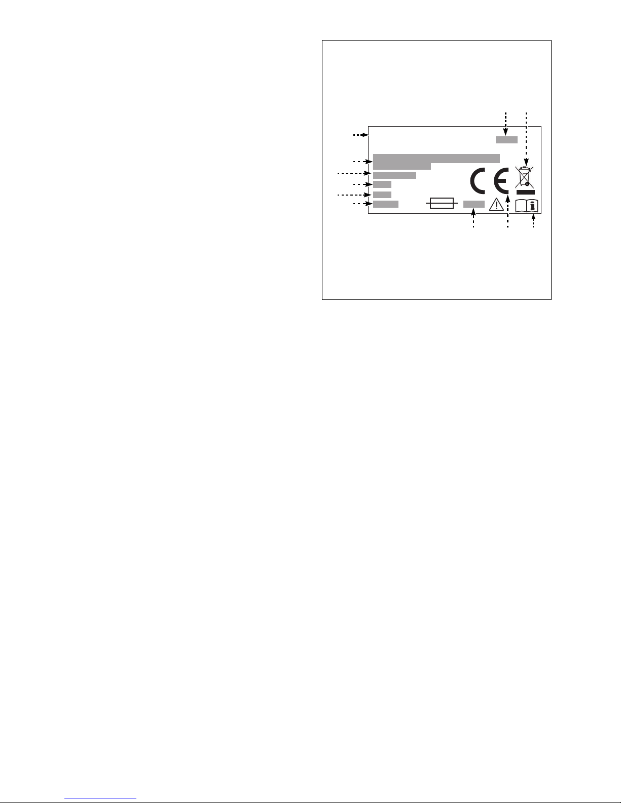
The shown identification label is available directly on the dispenser (one at the back, another close to drip tray). That label resumes
identification data as model and serial
number, and all the information to start the
dispenser up in safety conditions.
A) Manufacturer identification
B) Mark: reference country compliance ini-
tials
C) Model/ Serial number
D) Manufacturing date
E) Voltage and frequency
F) Electrical power installed
G) Protection rate
H) Class category
L) Fuse characteristics.
M) Electric and electronic equipment ref-
erence (Law 2002/96 CE)
N) Reminder advising to consult operative instructions
SERVICE REQUEST
In case of need please refer to ENOMATIC service team or to authorized technicians only.
Should service be required, please always provide identification data printed on the label
and occurred malfunctions.
ATTACHED DOCUMENTS
Attached to this manual, listed documentation is provided.
– Declaration CE of compliance
– Warranty statement
– Poured bottles tracking chart
enomatic s.r.l.
Via di Meleto, 1/19 - Greve in Chianti - (FI) - ITALY
IDM-46200300100.pdf
C
F
H
E
G
A
L B
D M
N
Page 6

C146200300.fm
- 4 -
TECHNICAL INFO
DISPENSER GENERAL DESCRIPTION
– ENOLINE 4 SMART is a dispenser designed and manufactured to pour and enjoy rare
wines by glass.
Main dispenser features are to provide wine flavour and scent preservation from oxidation, to avoid overpouring and waste.
– The dispenser is equipped with a refrigeration unit, perfect to enjoy white and rosè
wines.
– The dispenser is equipped with capacitive control panel.
Just by touching the control panel it's possible to select the wine and pour desired dose.
– Pictures and descriptions reported in this manual refer to ENOLINE 4 SMART dispens-
ers – to be used behind the bars (restaurants, wine bars, ecc).
– Please refer to chapter "Technical data" for more details on dimensions and technical
features.
MAIN DEVICES
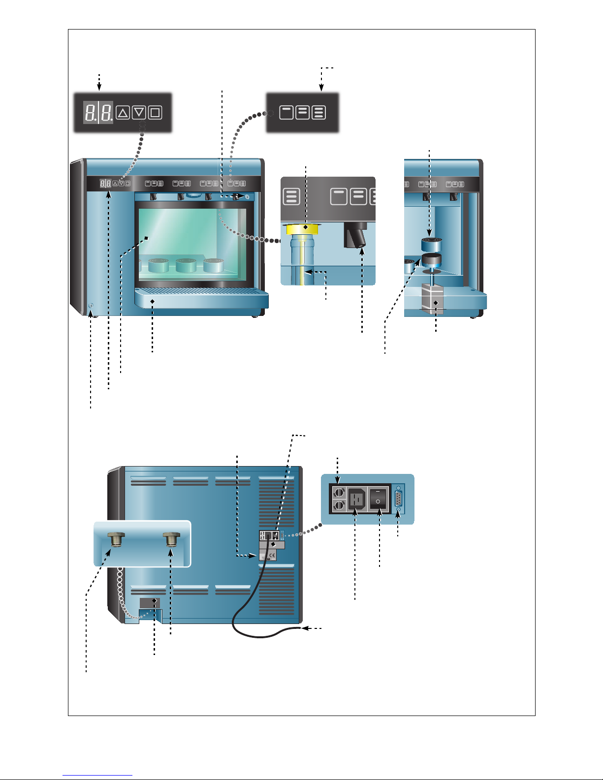
Regarding installation requirements the device can be supplied "right" or "left" side.
Picture shows left hand ENOLINE 4 SMART main devices.
Page 7
C146200300.fm
- 5 -
enomatic s.r.l.
Via il Mascherone, 33 - Panzano in Chianti Firenze
Control panel
IDM-46200300200.pdf
Thermostat
Dispensing buttons
Bottle neck
fitting
Straw
Dispensing spout
Pneumatic cylinder
Spacer
Bottle holder
Drip tray
Door
Dispenser
identification label
Fuses
Electric features label
Gas supply (wine dispensing)
Gas identification label
Gas supply (bottle lifting)
Serial connector
Electrical supply switch
Electrical socket
Electrical supply cord
Door lock
Dispensing key lock
Page 8
C146200300.fm
- 6 -
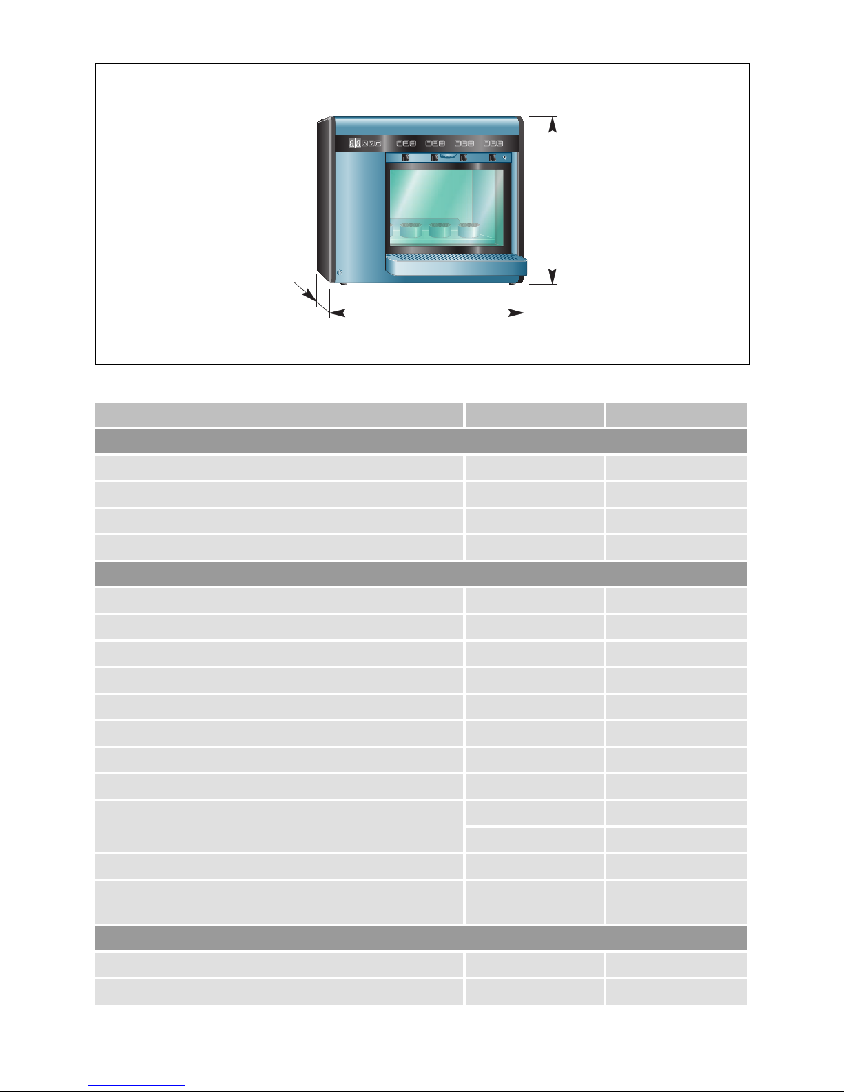
TECHNICAL DATA
Chart 1: Dispenser technical data
Description Measure unit Value
Dimensions
Length (L) mm 750
Height (H) mm 640
Width (S) mm 240
Weight kg 42
Dispenser features
Number of bottle 4
Wine preservation temperature °C 7÷18
Electrical power W 150
Electrical voltage V 110-220
Electrical frequency Hz 50-60
Auxiliary circuit voltage Vdc 24
Protection rate IP 20
Fuses quantity 2
Fuses value
A (220V) 4
A (110V) 8
Gas (air/nitrogen) duty pressure for bottle lifting line bar 4
Gas (argon/nitrogen) duty pressure for wine dispensing
line
bar 0,160
Bottle features
Height mm 280÷355
Maximal diameter mm 100
H
S
L
IDM-46200300300.pdf
Page 9

C146200300.fm
- 7 -
PROVIDED ACCESSORIES
The dispenser is provided by following listed accessories.
– 1x electric supply cord
– 2x holders to secure the dispenser to the wall
– 1x spirit level
– 1x kit of straws
– 1x dispensing tap seals
– 2x fuses
SAFETY WARNINGS
SAFETY GENERAL WARNINGS
– The Manufacturer, when designing and realizing the dispensers, took relevant care in
foreseeing and avoid any risk to user's health. The Manufacturer accomplished the laws
and adopted best available know-how in designing and realizing the dispenser. This information is to warn users about possible risky behaviours and how to avoid them. However precaution is essential and mandatory. Safety depends by users as well.
Before starting the dispenser for the first time it's strongly advised to completely
read this manual and fully comprehend the contents, especially safety warnings.
– Take a bit of time to read and comprehend the content of this manual, it will help to avoid
risky conditions and behaviours. It would be too late to do what should have already
been done if an accident happened.
– In case of lifting and/or moving respect instructions reported on the package, on the dis-
penser and in supplied manuals.
– Pay attention to the symbols on the labels; shapes and colours refer to important notices
about safety. Keep them in good condition.
– Only persons who read and comprehended the content of the manual are allowed to use
the dispenser.
– The dispenser must be installed in a dry environment provided by enough fresh air flow
as per Manufacturer's warn.
Environment data
Duty environment temperature °C 10÷25
Max relative humidity (Rhu) Rhu 60%
Chart 1: Dispenser technical data
Description Measure unit Value
Page 10

C146200300.fm
- 8 -
– The dispenser must be used as per projected purpose only. Improper use or misuse
may result into risky conditions and economic damages.
– When operating the dispenser, please ensure that there are no potential health and
safety hazards involved, particularly for children and disabled.
– Do not modify any device/component inside the dispenser. Any service not described in
this manual must be run by qualified personnel especially authorized by the Manufacturer. Use only original spare parts.
– Keep the dispenser in perfect duty conditions and run operations described in this man-
ual. A good maintenance will permit to keep the dispenser fully performing for long time
and to maintain high safety standards.
– Never wash the dispenser or lead water jets towards external or internal parts of it; that
is to avoid electronic device failures and/or damages.
Never run any maintenance service if the dispenser is electrically supplied, but prior remove the electric supply cord. Make sure it will remain unplugged till the end of the service.
– Electric cord must be carefully dropped to avoid person hindrance, hot surfaces near-
ness or general damages.
– Do not operate the dispenser in case of damaged plug or electric cord.
– Never clean the dispenser with corrosive products or abrasive materials.
– Never connect electrical cord if dispenser electrical features don't match supplied volt-
age/frequency/power values and laws.
– Before leaving and after having left the dispenser out of duty for long time always run
maintenance operations to grant hygienic conditions.
– Never install the dispenser in critic environment, as explosion or fire risk, next to heat
sources or food contamination rooms. The dispenser doesn't have to be exposed to any
atmospheric agents or to corrosive exhalations.
Page 11

C146200300.fm
- 9 -
ENVIRONMENT EFFECTS SAFETY WARNINGS
– Every organization has to apply specified procedures to estimate the effects its activities
(goods, services, ecc.) may have on the environment.
– Procedure to identify meaningful environment effects must consider following items.
– Exhaust
– Drainage
– Dispose
– Ground pollution
– Raw materials and natural resources use
– Environment effects local issues
– In order to reduce environment effects the Manufactures provides important information
that every user operating the dispenser, for any reason, must be aware of.
– All package components must be disposed respecting actual laws.
– During the installation the environment must be provided by exhaust ducts to ensure
fresh air to operators.
– During use and maintenance, do not dispose degraded products (oil, grease, ecc) in the
environment, or better select the disposal by raw material respecting actual laws.
– Keep noise level at minimum to reduce noise pollution.
– When dismissing, select the components by chemical features and dispose them re-
specting actual laws.
– In accomplish to RAEE (Electric Electronics Apparatus Rubbish) law the user must sep-
arately dispose all electric and electronic components and heading them to specified
collection areas, or delivery the dispenser in full performance to local distributor in reason of a new purchase.
– All components required to be separately or particularly disposed are
specifically marked.
Illegal disposal of materials listed in RAEE law will be punished
by local laws where the crime is committed.
Page 12
C146200300.fm
- 10 -
INFORMATION ON TRANSFER AND INSTALLATION
PACKAGE AND UNPACKAGE
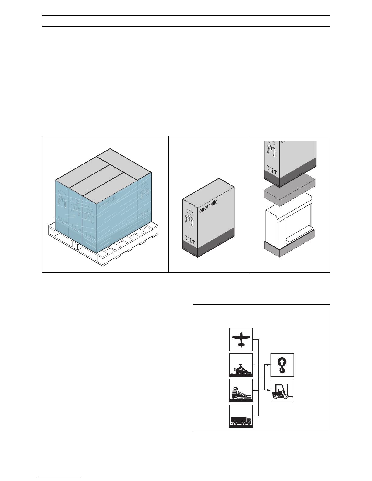
– The dispenser is packed in a specific package, and its external surfaces are protected
by a special film. When unpacking, carefully eject the dispenser and make sure it is intact.
Should some part be damaged or missing, never install the dispenser and contact an
ENOMATIC authorized dealer to schedule future actions.
– Important information on dispenser safe transfer are reported on the package.
Package must be disposal according actual laws and rules.
Safely store the package in case of eventual further transfer.
TRANSPORTING AND STORING
– Transportation, regarding the place of ar-
rival, can be done through different
means.
The diagram shows most adopted solutions.
– In order to protect the dispenser during
transportation, it is properly packed.
During transportation, the package must
remain in vertical position as shown by
symbols on it.
Important information on dispenser safe
transfer are reported on the package.
IDM-46200301900.pdf
Transportation means
Lifting dispensers
Page 13
C146200300.fm
- 11 -
Handle the package with care paying attention not to overturn it and damage the dispenser.
– Should the dispenser be installed later its arrival, it must be stored in a dry and protected
environment with temperature range between 0° and 40°.
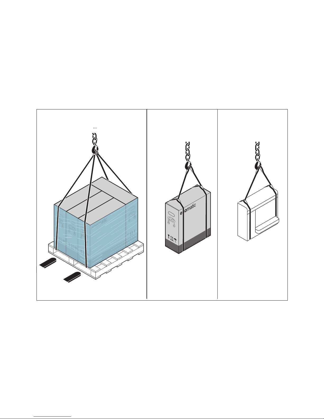
TRANSFER AND LIFTING
The dispenser can be transferred and lifted by fork-provided or hook devices. Before that,
carefully check load's centre of gravity.
Illustrations show most adopted transfer and lifting methods.
IDM-46200302000.pdf
Page 14

C146200300.fm
- 12 -
"PACKAGE LIST" AND DISPENSER INTEGRITY CHECK.
– Every delivery is provided by a document reporting package list and description.
– When receiving the packages, always refer to "Packing List" to check package numbers
and integrity.
Should some part be damaged or missing, never install the dispenser and contact an
ENOMATIC authorized dealer to schedule future actions.
WARNING FOR INSTALLATION AND CONNECTIONS
Installation, connection and start up must be run by qualified personnel authorized
by the Manufacturer.
– Before running the installation, a proper place where to settle the dispenser and nitro-
gen/argon tanks must be advised by the ENOMATIC technician.
– Before electrical connection, make sure that provided voltage/frequency/power values
correspond to actual laws and what shown on dispenser identification label.
Page 15
C146200300.fm
- 13 -
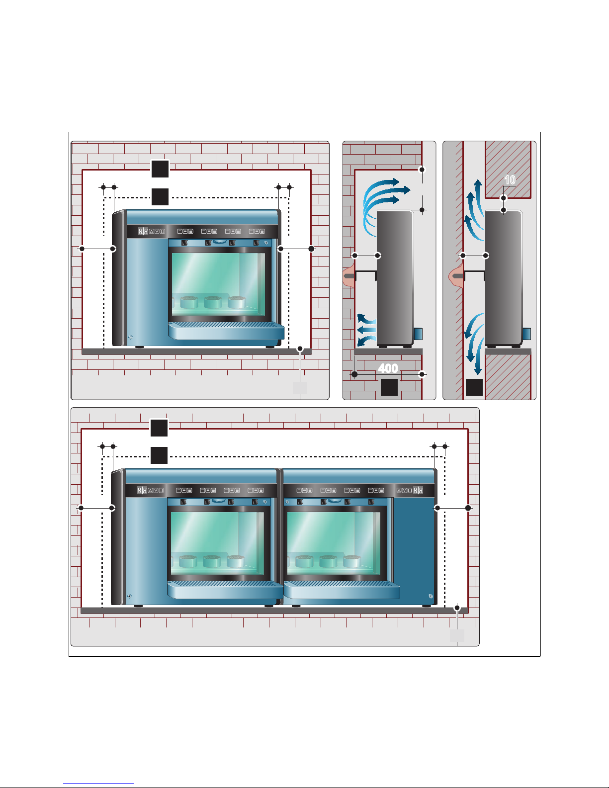
INSTALLATION AND CONNECTION
Act as per instruction.
1. Settle the dispenser in foreseen area.
Illustration shows minimal distances to grant adequate ventilation.
2. Proportion gas supply duct regarding the features involved in the installation (nitrogen/
argon tanks, nitrogen generator, etc.).
Legend
A = No air duct installation example
B = Air duct installation example
B
100
250
100
400
A
1010
900
100 100
A
B
A
B
1010
900
100 100
10
IDM-46200300400.pdf
Page 16
C146200300.fm
- 14 -
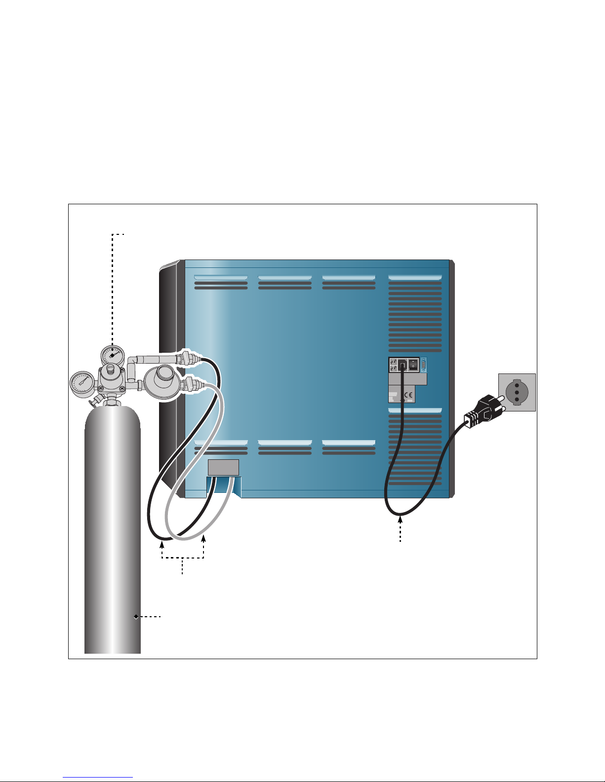
3. Connect gas supply pipes to relative inlets.
4. Correct the stance of the dispenser acting on adjustable feet to ensure proper working
condition.
5. Check dispenser stability and, if necessary, ensure it to the wall fixing provided holders.
6. Plug the electrical supply cord to the device.
Before plugging the cord to the electrical socket, turn main switch to OFF position
and make sure to provide voltage/frequency/power values as shown on identification
label.
7. Check dispenser working condition making sure to avoid flood leaks (air, nitrogen/argon, etc.).
enomatic s.r.l.
Via il Mascherone, 33 - Panzano in Chianti Firenze
N2
IDM-46200300500.pdf
Valve
4 Bar
0,160 Bar
110 - 220 V
50 - 60 Hz
Electrical supply cord
Gas supply pipe (Ø 4mm)
Gas tank
Page 17
C146200300.fm
- 15 -
FUNCTIONS AND USE
DISPENSER USE (FIRST TIME)
When operating the dispenser for the first time, some specific procedures will be run; those
will not be repeated when in regular use.
Act as per instruction.
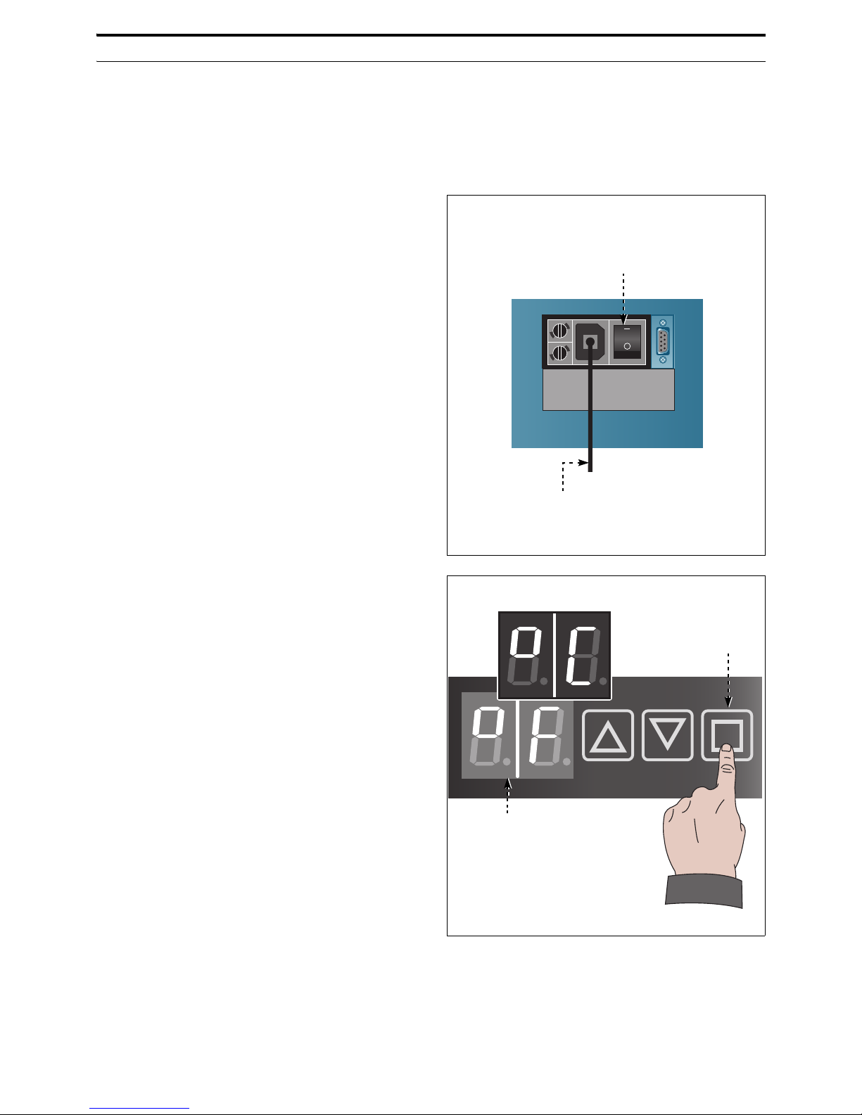
1. Make sure to have turned main electrical
switch (A) to O (OFF) position.
2. Make sure to have plugged electrical cord
(B).
3. Supply gas to the dispenser and check
correct pressure value.
4. Turn switch (A) to I (ON).
All buttons will lamp and the dispenser
runs a quick check-up.
When check-up is finished, buttons turn
off.
5. Display (M) will show possible temperature scales.
– Celsius (°C) temperature scale.
– Fahrenheit (°F) temperature scale.
6. Touch the button (L) to select desired
temperature scale.
IDM-46200300600.pdf
Electrical supply switch (A)
Electrical supply cord (B)
IDM-46200302100.pdf
Display (M)
Button (L)
Page 18
C146200300.fm
- 16 -
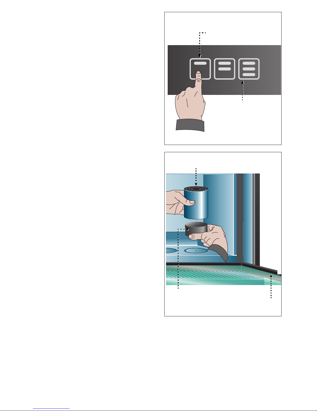
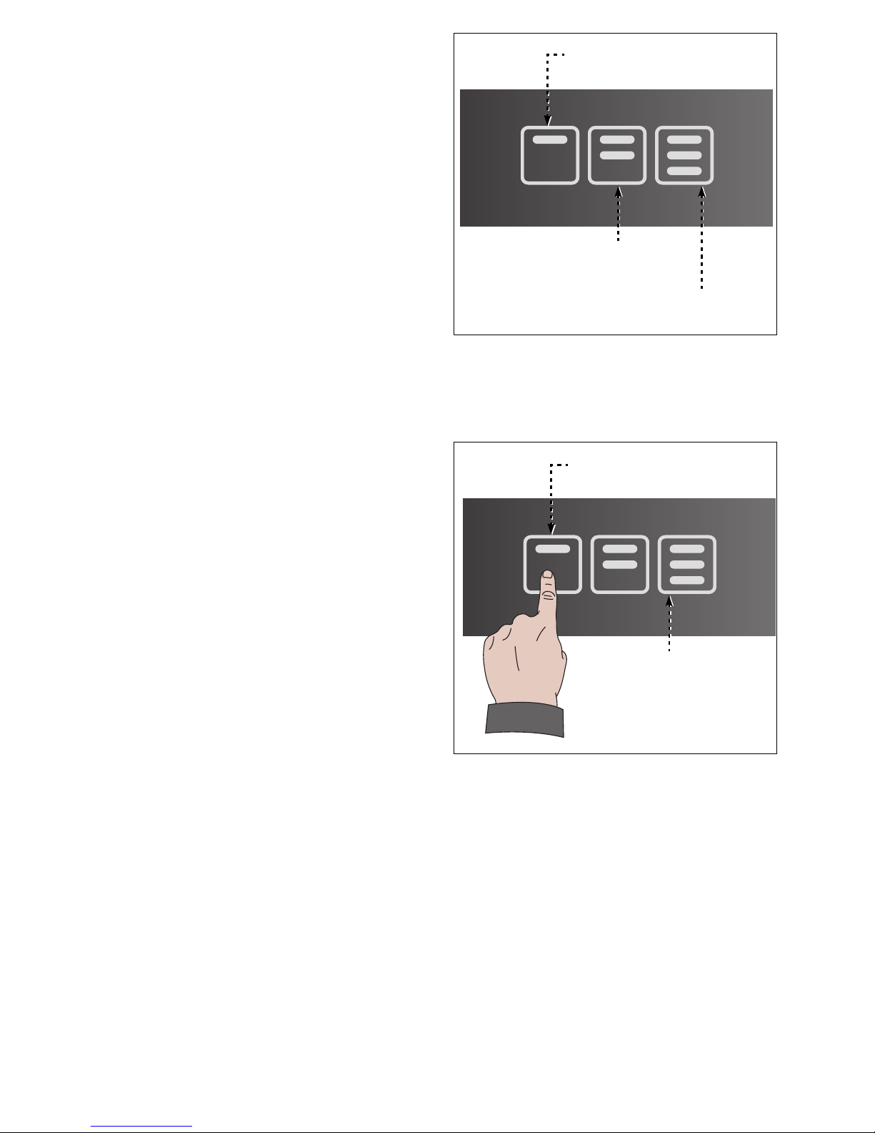
7. Quickly tap buttons (1-3) in sequence "13-1" to completely lower the cylinder.
Repeat the action on other buttons to lower one by one all other bottle pistons.
8. Open the door (H).
9. Remove the supports (C).
IDM-46200300700.pdf
Volume "taste" (1)
Volume "full glass" (3)
IDM-46200300800.pdf
Spacer (D)
Bottle holder (C)
Door (H)
Page 19
C146200300.fm
- 17 -
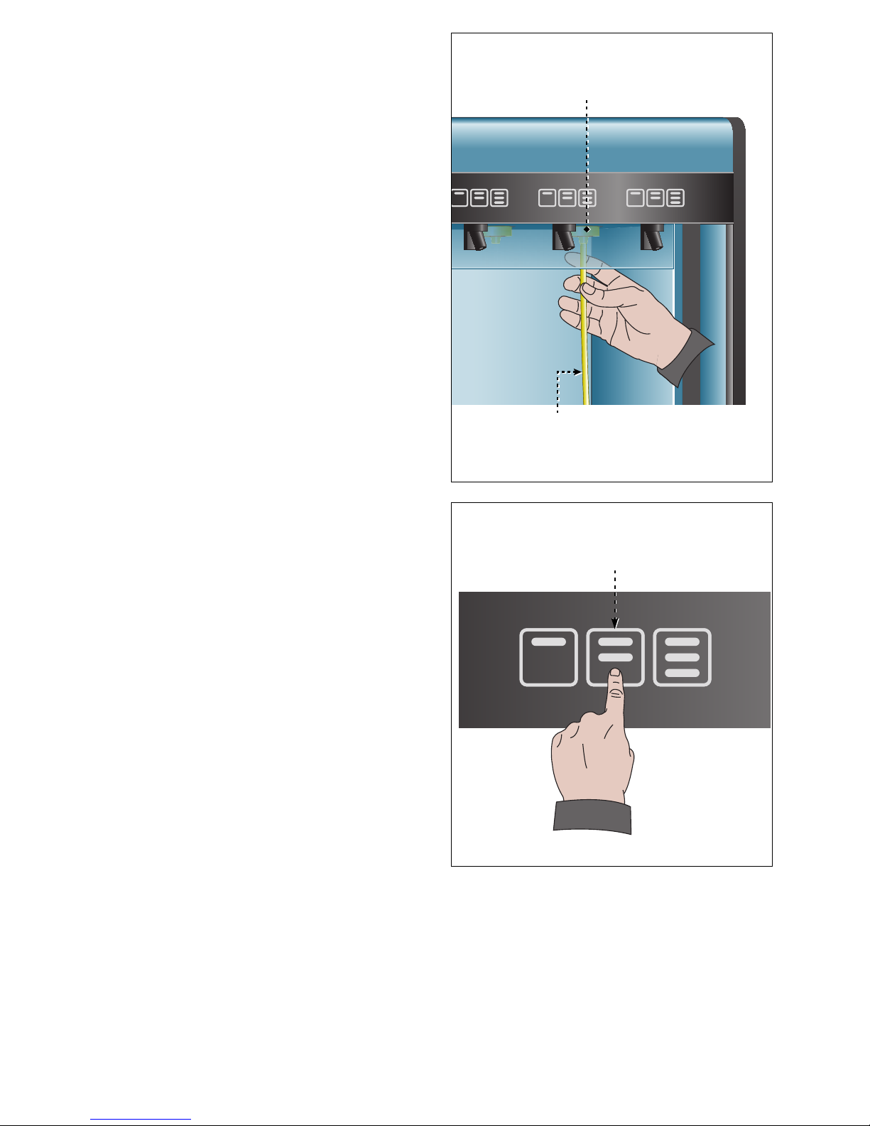
10. Insert the straw (E) into all dispensing
taps (F).
Straws must be completely inserted in order to grant correct working condition.
11. Open the bottle you desire to engage.
12. Thoroughly clean bottle neck upper part
removing all foreign objects and ensuring
it is intact to provide correct sealing.
13. Insert the straw (E) into the bottle to engage on bottle piston (C).
In case the bottle neck is further than 3cm
from dispensing tap, add one or two
spacers (D) inside bottle piston (C).
14. Check that filter straw reaches the bottom
of the bottle.
Should the wines feature sediments, snip
the straw to avoid the filter reaches the
bottom of the bottle.
15. Touch the button (2) to raise the cylinder
(C).
16. Bottle neck must properly fit the dispensing tap adapter in order to avoid nitrogen/
argon leaks.
When the bottle is properly engaged, related buttons turn on.
Each dispensing tap buttons are off if the
bottle is not engaged.
17. Repeat the action to set one by one all the
bottles on piston to engage them into related dispensing tap.
IDM-46200300900.pdf
Bottle neck fitting (F)
Straw (E)
IDM-46200301000.pdf
Volume "half glass" (2)
Page 20
C146200300.fm
- 18 -
In case of one or more cylinders remain lowered, they will lift automatically up after
about 90 seconds.
18. Close the door (H).
19. Configure the volumes and the temperatures when all dispensing taps buttons are
turned on (See "Volume configuration" - "Temperature configuration").
The dispenser must be turned off in case a long period of inactivity is foreseen. This
is to avoid cooled air waste.
The dispenser doesn't have to be turned off in case a short period of inactivity is foreseen.
Dispensing taps can be disabled by key lock (leave power on) to preserve wine temperature.
DISPENSER USE (AFTER FIRST TIME)
Act as per instruction.
1. Make sure first-use procedures have been run (See "Dispenser use (first time)").
2. Make sure electric supply is on.
Buttons are on when a bottle is engaged in related dispensing tap.
3. Make sure gas line is on.
4. Make sure proper pressure value is supplied.
The dispenser must be turned off in case a long period of inactivity is foreseen. This
is to avoid cooled air waste.
The dispenser doesn't have to be turned off in case a short period of inactivity is foreseen.
Dispensing taps can be disabled by key lock (leave power on) to preserve wine temperature.
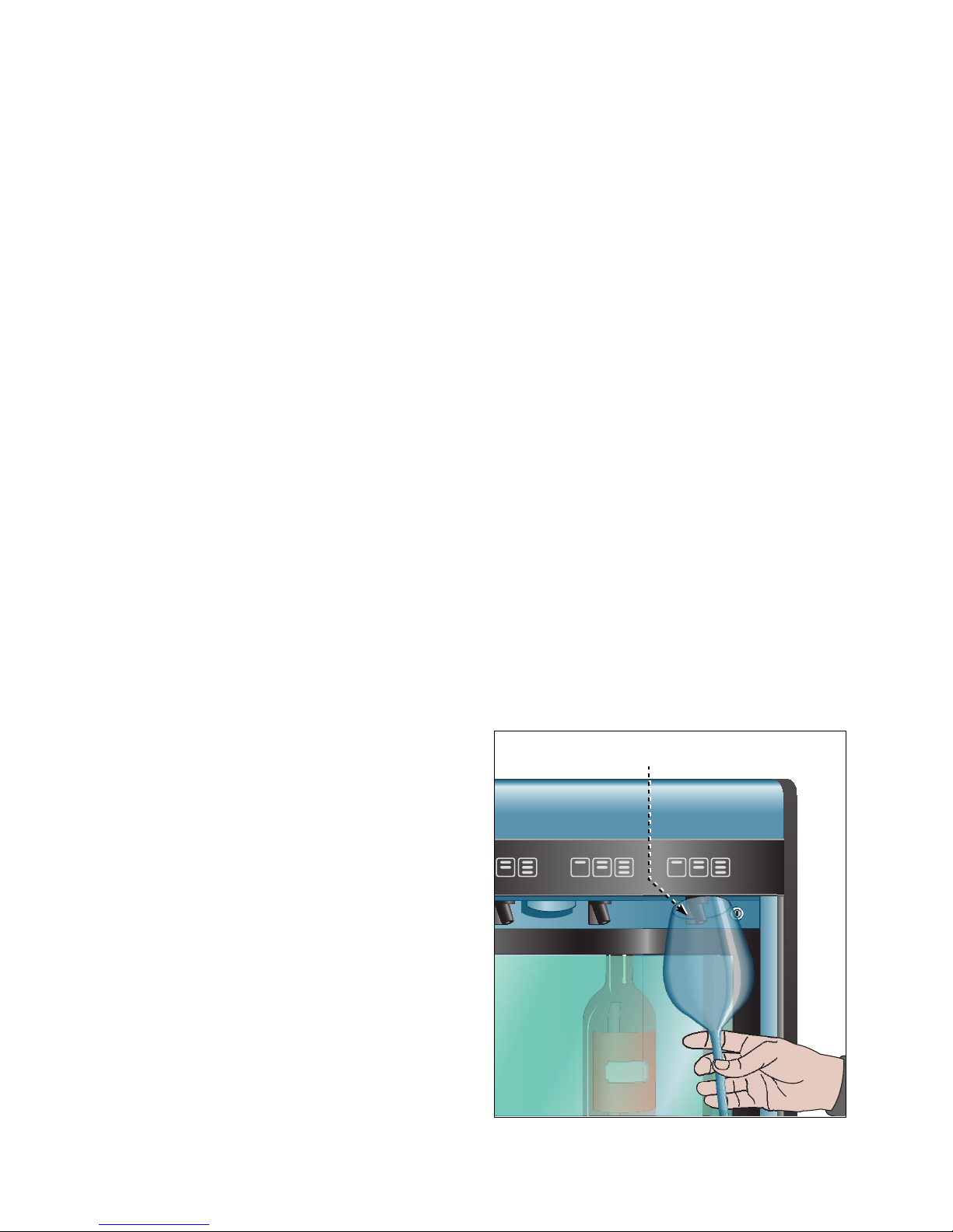
5. Place the glass inside serving spout (G).
IDM-46200301100.pdf
Dispensing spout (G)
Page 21
C146200300.fm
- 19 -
6. Touch one of buttons (1-2-3) related to
dispensing tap where desired wine is engaged to pour requested volume.
Illustration shows buttons to pour requested
doses.
1) Volume "taste"
2) Volume "half glass"
3) Volume "full glass"
Press desired button and release when pour
starts.
Pour ends when configured volume is dispensed.
7. When pour is finished, wait for a few second and then remove the glass from the
spout (G)
WINE BOTTLE REPLACEMENT
When a bottle replacement is required, act as
per instruction.
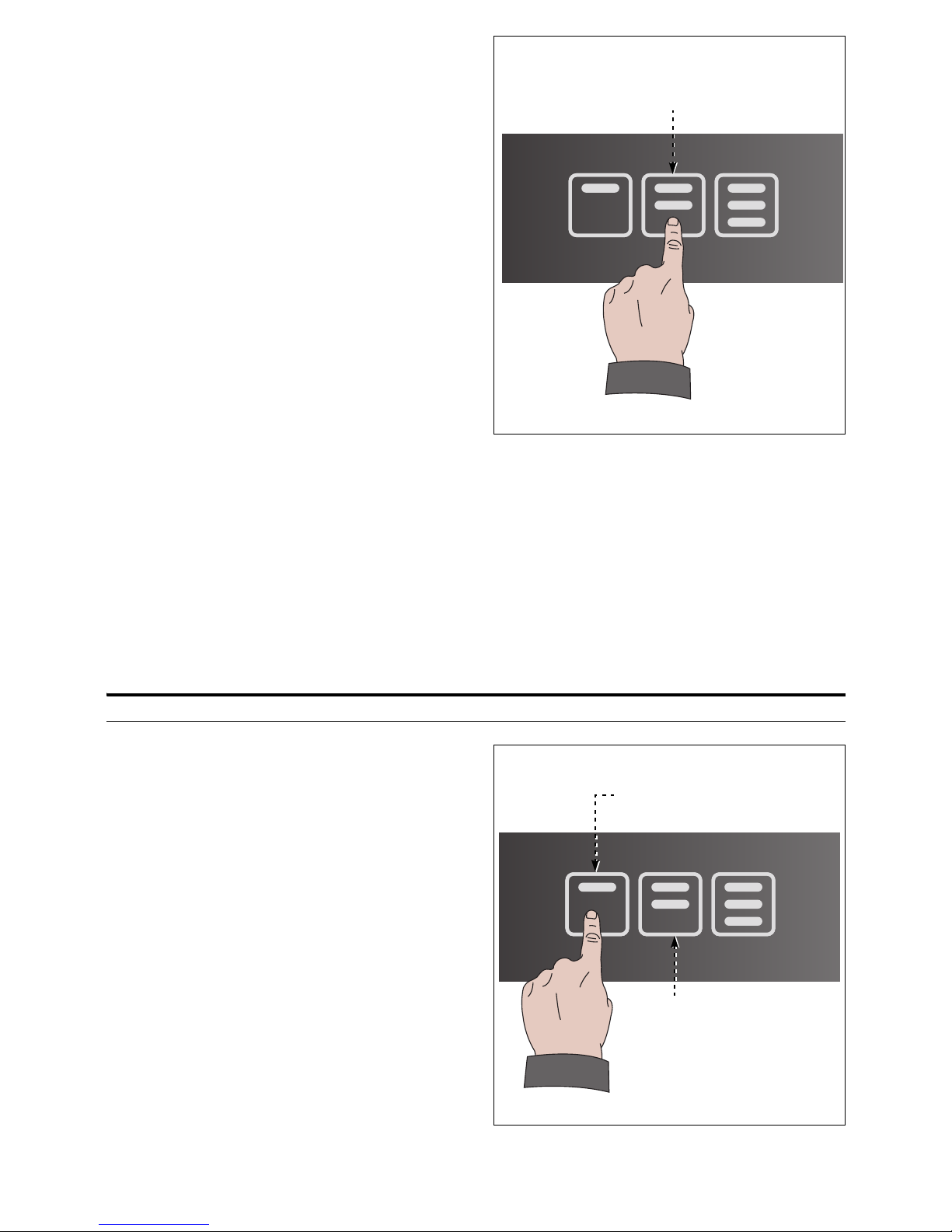
1. Quickly tap buttons (1-3) in sequence "13-1" to completely lower the cylinder.
When the cylinder is lowered, buttons
turn off.
2. Open the door.
3. Remove the bottle from the straw and replace it with the same type of wine.
Bottles to be engaged must be at same
pouring temperature (±1 °C tolerance).
Bottles must be quickly removed and engaged to reduce cooled air waste.
– A small quantity of wine will remain Inside
straw. It will mix with next bottle wine.
In case a different type of wine will be engaged, remove the straw from dispensing
tap and flush it under water or replace it to avoid different wines' mix.
Volume "half glass" (2)
IDM-46200301600.pdf
Volume "full glass" (3)
Volume "taste" (1)
IDM-46200300700.pdf
Volume "taste" (1)
Volume "full glass" (3)
Page 22
C146200300.fm
- 20 -
4. Touch the button (2) to raise the cylinder.
Bottle neck must properly fit the dispensing tap adapter in order to avoid nitrogen/
argon leaks.
When the bottle is properly engaged, related buttons turn on.
5. Close the door.
VOLUME CONFIGURATION
Volumes can be configured as listed.
– Single configuration: procedure to individually setup volumes to be poured on each sin-
gle button, and for each single dispensing tap.
– Multiple configuration: procedure to setup volumes to be poured on each single tap that
will be copied onto same type buttons of remaining dispensing taps..
Single configuration
1. Quickly tap buttons (1-2) in sequence "12-1" to start volume configuration procedure.
Buttons start blinking.
IDM-46200301000.pdf
Volume "half glass" (2)
IDM-46200301700.pdf
Volume "taste" (1)
Volume "half glass"
(2)
Page 23
C146200300.fm
- 21 -
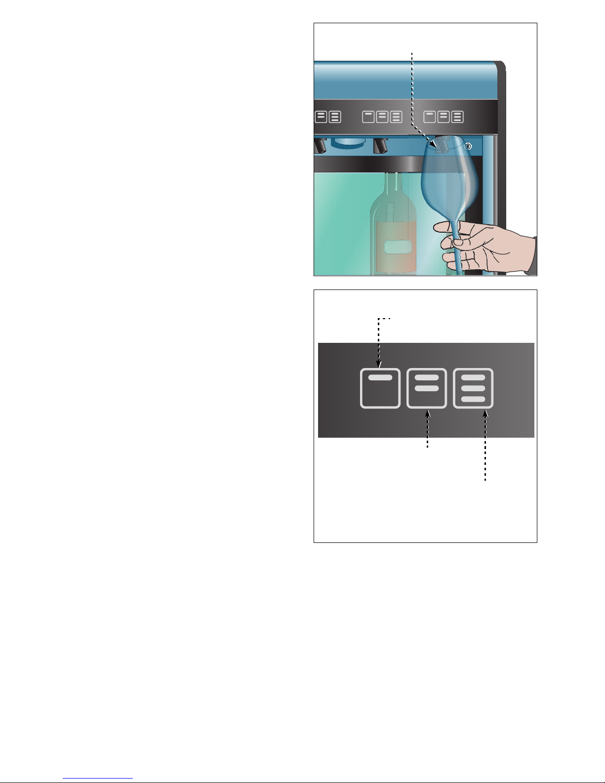
2. Place the glass inside serving spout (G).
3. Touch desired buttons and release it
when poured wine has reached requested quantity.
4. Repeat the procedure on dispensing tap
remaining buttons to configure related
volumes.
5. Configure volumes related to all other
buttons following same procedure.
Time elapsing between different buttons
configuration can not be longer than 10
seconds.
If time is more than 10 seconds it is required to restart configuration procedure.
IDM-46200301100.pdf
Dispensing spout (G)
Volume "half glass" (2)
IDM-46200301600.pdf
Volume "full glass" (3)
Volume "taste" (1)
Page 24
C146200300.fm
- 22 -
Multiple configuration
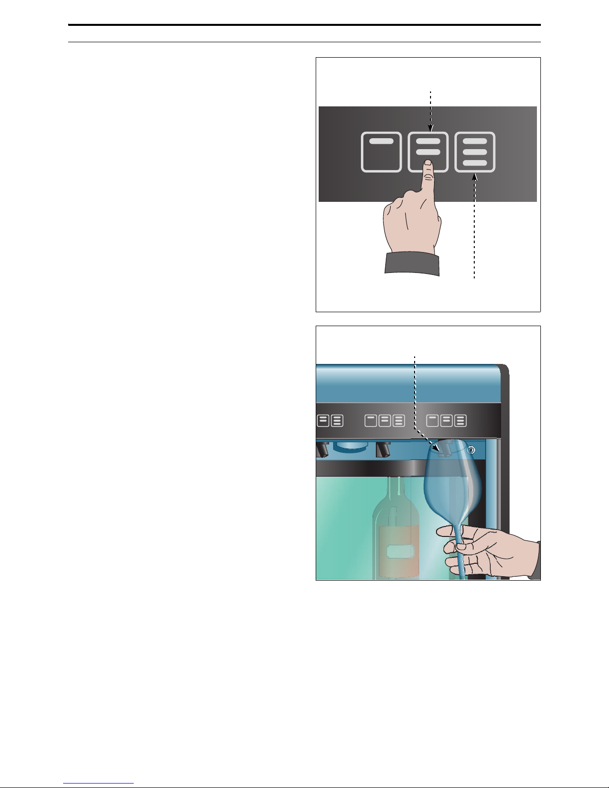
1. Quickly tap buttons (2-3) in sequence "23-2" to start volume configuration procedure.
Buttons start blinking.
2. Place the glass inside serving spout (G).
IDM-46200301800.pdf
Volume "half glass" (2)
Volume "full glass" (3)
IDM-46200301100.pdf
Dispensing spout (G)
Page 25
C146200300.fm
- 23 -
3. Touch desired buttons and release it
when poured wine has reached requested quantity.
4. Complete the procedure on dispensing
tap remaining two buttons
Configuration will be automatically copied to all other dispensing taps buttons.
Time elapsing between different buttons
configuration can not be longer than 10
seconds.
If time is more than 10 seconds it is required to restart configuration procedure.
TEMPERATURE CONFIGURATION
Act as per instruction.
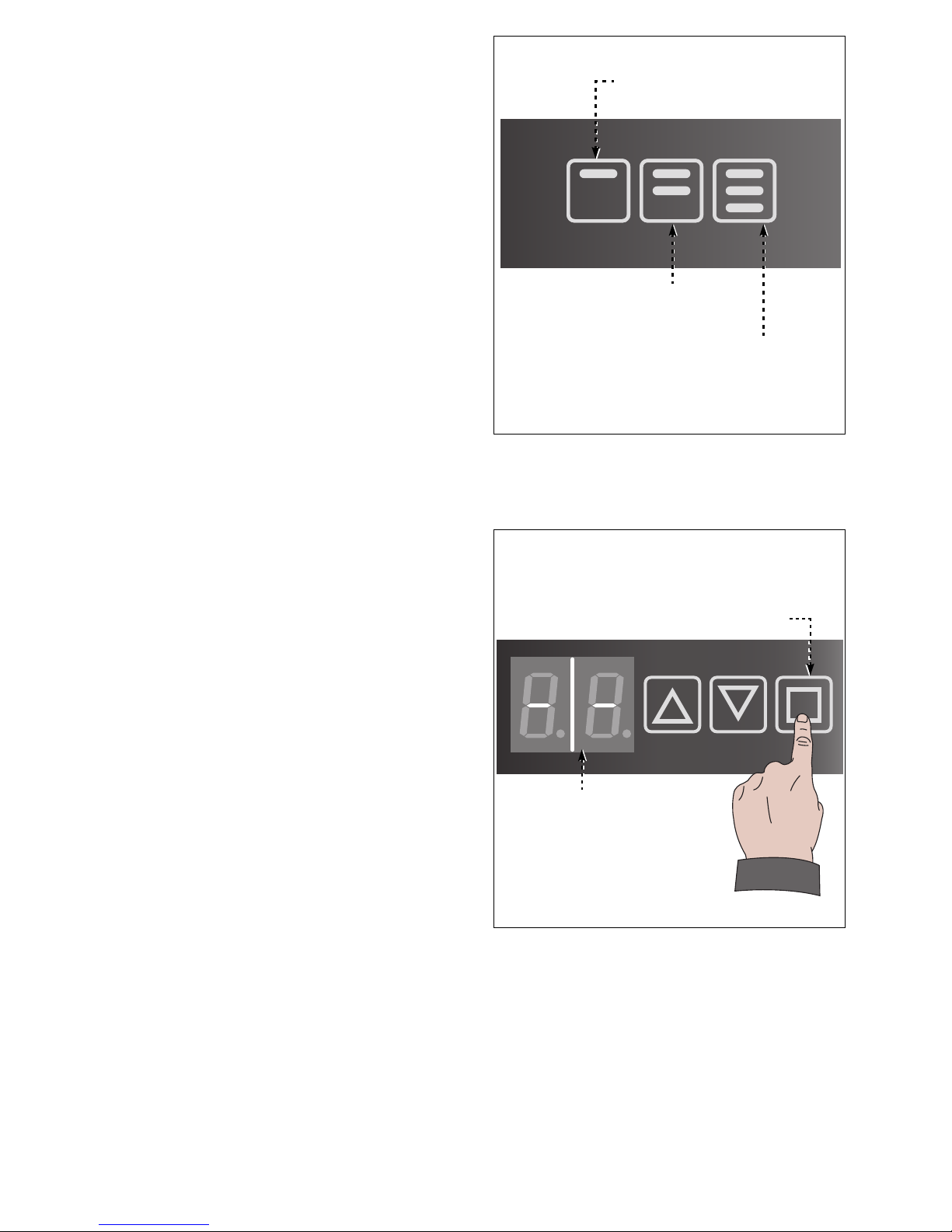
1. Touch the button (L). Display (M) will
show two hyphens.
Volume "half glass" (2)
IDM-46200301600.pdf
Volume "full glass" (3)
Volume "taste" (1)
IDM-46200301200.pdf
Display (M)
Button (L)
Page 26
C146200300.fm
- 24 -
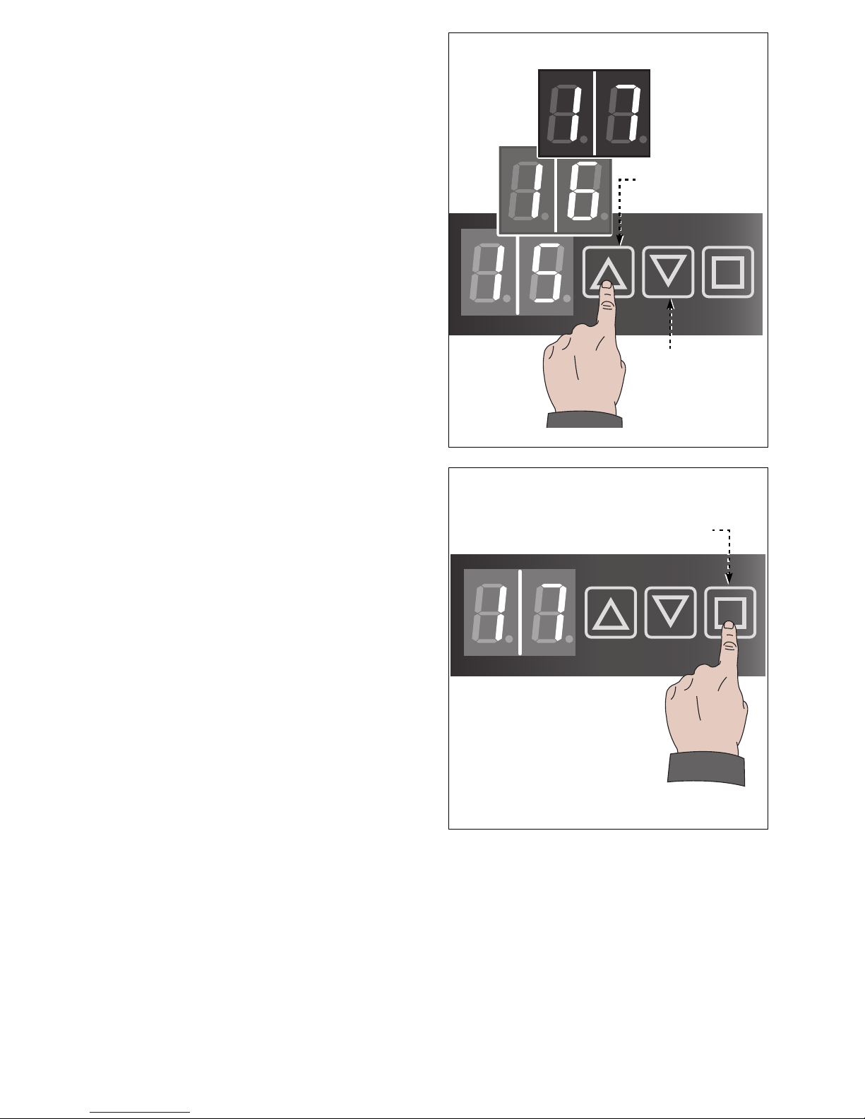
2. Touch one of buttons (N-P) to increase or
decrease the temperature.
3. Touch the button (L) to confirm the value.
Bottles chamber will be kept at setup temperature.
Bottles must be quickly removed and engaged to reduce cooled air waste.
IDM-46200301300.pdf
Button (P)
Button (N)
IDM-46200301400.pdf
Button (L)
Page 27
C146200300.fm
- 25 -
DEFROST MODE
Act as per instruction.
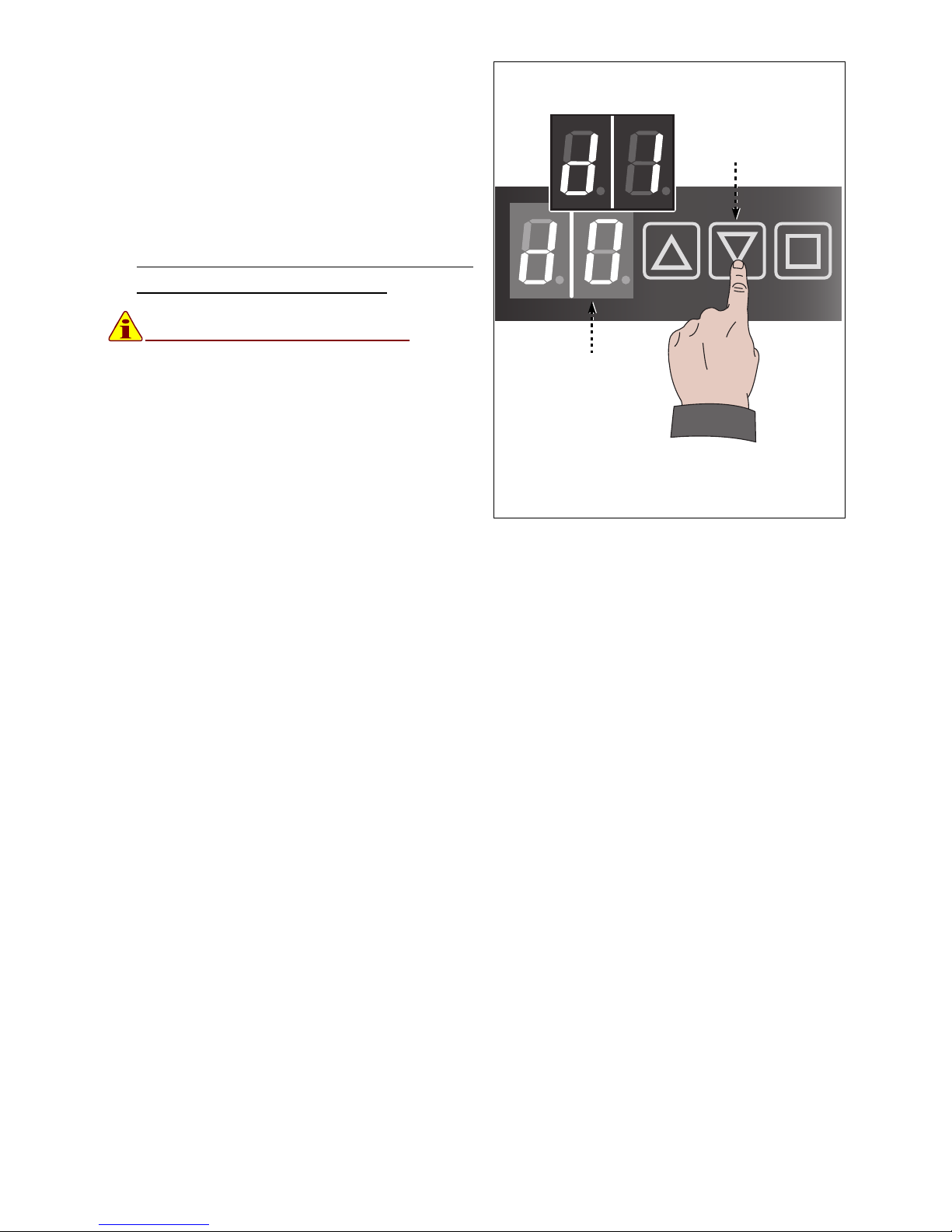
Touch about 2 seconds button (P)
Display (M) shows duty status reference.
– "d0": function disabled
– "d1": function enabled
After about 5 seconds, display will show temperature value again (°C).
Defrost cycle ON is shown by dots
next to digits on display (M).
Information
In case of uncompleted ice melt when
defrost is over, turn the dispenser off
to end melting process. Should the
problem persist, please contact Enomatic Technical Service or your local
agent.
IDM-46200301500.pdf
Display (M)
Button (P)
Page 28

C146200300.fm
- 26 -
MAINTENANCE INFORMATION
MAINTENANCE WARNINGS
Run maintenance actions scheduled by the Manufacturer. They will permit to maintain high
levels of efficiency and to grant that full performances will last long.
The manufacturer will not be liable in any way for any damage that may be caused by the
use of not original spare parts, which may result into personal injury or reduce safety level.
Clean external parts using warm water and a soft clothe, or a food grade cleaning
agent. Never use abrasive or corrosive materials.
SCHEDULED MAINTENANCE CHART
(*) In case sweet or particularly sediment wines are poured, double the frequency of the
cleaning.
Chart 2: Maintenance frequency
Frequency Device Action
Every bottle engagement Straw
Flush the straw under the water and clean it
with a soft clothe.
Daily
Dispensing spout
Dip the serving spout into a glass of water
and leave it there a couple of seconds in
order to clean internally the spout. Then
clean and dry the spout with a soft clothe.
Drip tray Clean the drip tray with a wet sponge.
General cleaning
Clean all the dispenser surfaces, especially
the dispensing area, with a damp and clean
clothe.
Every 10÷12 bottle
changes (*)
Dispensing tap
Sanitize the dispensing tap with a citric acidbased solution.
Every 6 months (*) Dispensing tap
Sanitize the dispensing tap with a food
grade detergent, specific for food
environments.
Page 29
C146200300.fm
- 27 -
DISPENSER SANIFICATION
Act as per instruction.
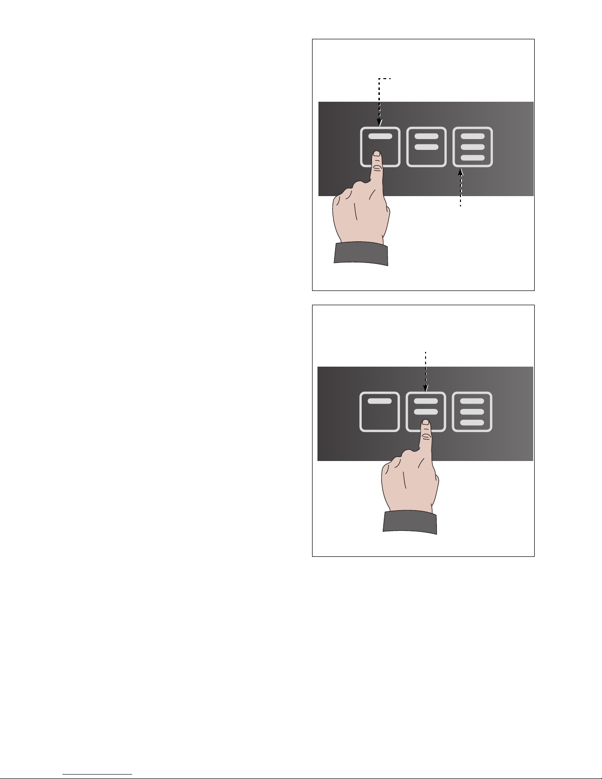
1. Quickly tap buttons (1-3) in sequence "13-1" to completely lower the cylinder.
When the cylinder is lowered, buttons
turn off.
2. Repeat the procedure on all dispensing
taps to lower the cylinders.
3. Open the door.
4. Remove all the bottles engaged in the
dispenser.
5. Full an empty bottle with a citric acidbased solution.
When preparing the citric acid-based solution, use about 15gr of citric acid each
750ml of water.
6. Insert the bottle following same procedure as per a normal wine bottle.
7. Touch the button 2 to pour enough detergent and sanitize.
8. Wait for few minutes before pouring
whole bottle content to completely sanitize.
9. Lower the cylinder to remove detergent
bottle.
10. Insert a bottle of drinkable water and pour
it completely until nitrogen/argon outcome.
11. Repeat sanitizing procedure on remaining taps.
Each dispensing tap can be sanitized at
different time, regarding the wine consumes. It's advisable to regularly fill the chart for full tracking capability.
Sanitize the dispenser before leaving and after having left it out of duty for long time.
IDM-46200300700.pdf
Volume "taste" (1)
Volume "full glass" (3)
IDM-46200301000.pdf
Volume "half glass" (2)
Page 30

C146200300.fm
- 28 -
TROUBLESHOOTING
TROUBLE, ORIGIN, SOLUTION
The dispenser, before installation, was previously checked.
Following information are to help the user to identify and correct malfunctions which may
happen during the use.
Some of those problems can be solved by the user, all others requiring specific technical
know-how must be faced only by skilled and qualified personnel with declared experience.
Chart 3: Malfunctions
Trouble Origin Solution
The dispenser doesn't switch on
Loss of electrical voltage supply. Check electrical connection
Not activated electrical supply
Turn bipolar switch to position I
(ON).
Fuse is burned up. Replace the fuse.
Dispensing tap buttons are off.
Bottle is missing
Engage the bottle in the
dispensing tap
The bottle can't reach the
dispensing tap
Insert one or more spacers to lift
the bottle piston
The bottle doesn't correctly fit
the dispensing tap
Properly fit bottle neck to
dispensing tap
The bottle was engaged when
the dispenser was off
Replace the bottle in the
dispensing tap
One or more dispensing tap
buttons are off.
The wine left in the bottle is not
enough to pour preset volume
Select a different dose or
replace the bottle
The wine is not fluently poured
The straw is not properly
inserted into the dispensing tap
Remove the bottle and firmly
push upwards the straw into the
dispensing tap
The filter of the straw is clog Clean the straw or replace it.
The nitrogen/argon to pour the
wine is run out or supply
pressure is fail
Restore proper nitrogen/argon
duty condition
Some wine drops fall from a
serving spout
Dispensing tap valves are clog
by some wine sediments
Sanitize the dispensing tap
Next to bottle neck pin (bottle
engaged) gas overflows.
The bottle doesn't correctly fit
the dispensing tap
Properly fit bottle neck to
dispensing tap
The bottle can't reach the
dispensing tap
Insert one or more spacers to lift
the bottle piston
Page 31

C146200300.fm
- 29 -
Next to bottle neck pin (no bottle
engaged) gas overflows.
Gas valve is open due clog
bottle neck pin.
Manually unlock bottle neck pin.
Sanitize the dispensing tap
Nitrogen comes out from
dispenser rear
Nitrogen/argon supply
connection is defective
Restore proper nitrogen/argon
duty condition
The piston lowers when a bottle
is engaged
Pressure supplying bottle lifting
pistons is fail or nitrogen/argon
tank is empty
Restore proper nitrogen/argon
duty condition
The wine is not poured at preset
temperature
Engaged bottle temperature is
higher or lower than the one
preset for pour
Replace the bottle in the
dispensing tap
The dispenser doesn't reach
preset temperature
Thermal facilities outlets aren't
properly ventilated (i.e. outlets
might be clog) or is out of order
Restore proper ventilation
condition for thermal facilities or
ask to an authorized Service
Centre for replacement
Chart 3: Malfunctions
Trouble Origin Solution
Page 32
C146200300.fm
- 30 -
INFORMATION ABOUT REPLACEMENTS
REPLACEMENT WARNINGS
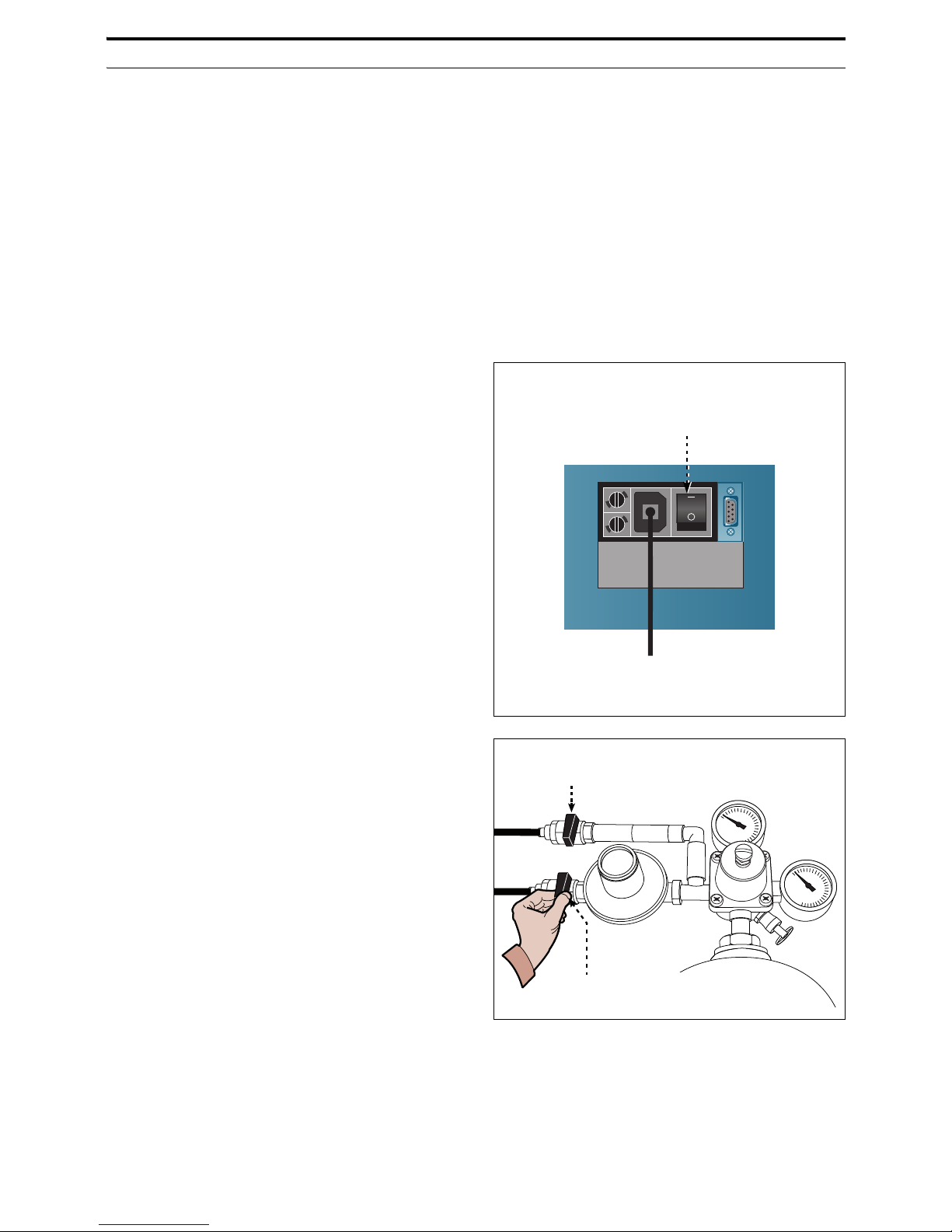
– Before running any maintenance service, always close nitrogen tank, turn switches to
off, unplug electric cord and disable all devices which may hurt persons if activated.
– Activate all necessary safety means and inform surrounding people.
– Should fatigue components need to be replaced, please use original spare parts only.
– Never modify duty features and safety devices and always use original spare parts.
Avoid the use of materials not authorized by the Manufacturer.
GAS TANK REPLACEMENT
Act as per instruction.
1. Replace the nitrogen tank as soon as
duty pressure reaches 5 bar.
2. Make sure the switch (A) in on O (OFF)
position.
3. Close nitrogen/argon supply faucet (H-
H1)
IDM-46200300610.pdf
Electrical supply
switch (A)
Dispensing Tap (H)
Dispensing Tap (H1)
IDM-46200103500.pdf
Page 33
C146200300.fm
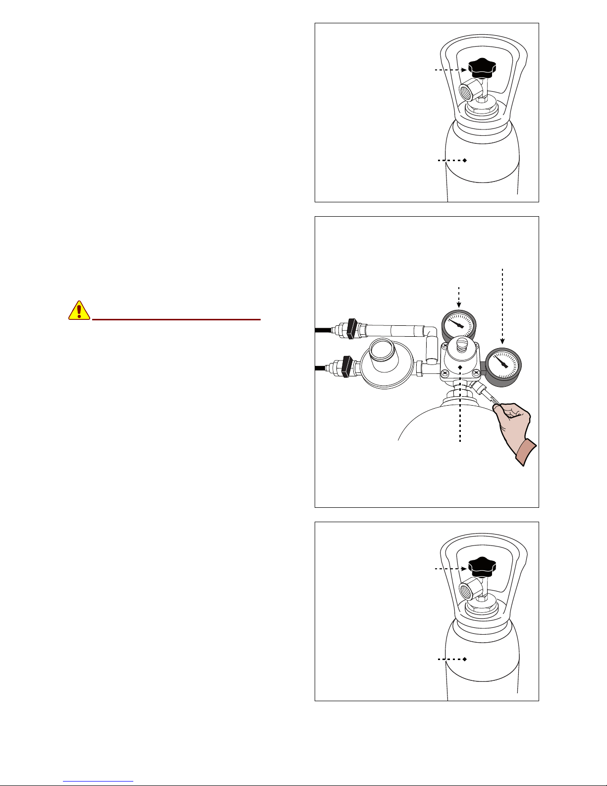
- 31 -
4. Close tank (K) handle (J).
5. Pull the ring of the valve (L) and keep it in
out position to discharge residual pressure inside the tank (K). Leave it when
manometers (M-M1) shows values 0 (zero).
Danger
Warning
Stay away from discharge valve to
avoid risk of hurt.
6. Remove the manometer and replace the
tank (K).
7. Check the sealing and replace it if necessary.
8. Tight the manometer to the full tank (K).
9. Open the handle (J) of the tank (K).
Dispensing Tap
(J)
Gas tank (K)
IDM-46200103600.pdf
Valve (L)
Manometer (M)
Manometer (M1)
IDM-46200103700.pdf
Dispensing Tap
(J)
Gas tank (K)
IDM-46200103600.pdf
Page 34
C146200300.fm
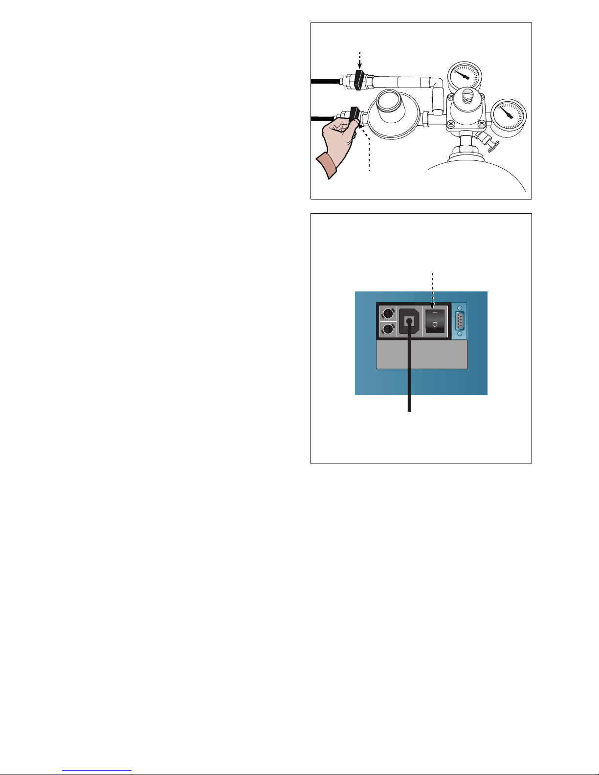
- 32 -
10. Open the nitrogen/argon supply faucet
(H-H1).
11. Turn bipolar switch (A) to position I (ON).
DISPENSER DISPOSAL AND DEMOLITION
– When disposing the dispenser it's necessary to execute some operations in order to
avoid hindrance or further uses.
– When demolishing the dispenser, select the parts upon chemical characteristics and
dispose them according actual laws.
– Never dispose chemical oils, not iron-made (rubber, plastic PVC, glues, etc.) pieces or
biohazard materials in the environment. Dispose them according to actual laws.
Dispensing Tap (H)
Dispensing Tap (H1)
IDM-46200103500.pdf
IDM-46200300610.pdf
Electrical supply switch (A)
Page 35

www.enomatic.com
Page 36
via di Meleto, 1/int.19
50027 Strada in Chianti (FI) - Italia
ph. (+39) 055 8547272 fax (+39) 055 8547488
[email protected] www.enomatic.com
NSF Certified
 Loading...