

Enoch Systems IEM-DB-7S-RS Quick Installation Manual

Product Installation Guide
,(,
IEM-DB-7S-RS
www.enochsystems.com
Copyright © 2013 Enoch Systems, LLC, Enoch Systems and the Enoch Systems logo are trademarks or registered trademarks of Enoch Systems, LLC and/or its affiliates in the U.S. and other countries.
Third-party trademarks mentioned are the property of their respective owners. All rights reserved.
1-877-722-1116 sales@enochsystems.com

1
Fall Function ETX Baseboard with VGA/LVDS/
TTL,Audio, CF type II & Digital I/O
IEM-DB-7S-RS
Quick Installation Guide
Version 3.0
May 25, 2007
Package Contents
IEM-DB-7S-RS-R30 package includes the following items:
1 x IEM-DB-7S-RS-R30 single board computer
1 x FDD cable
1 x HDD cable
1 x RS-232/422/485 cable
1 x Mini jumper pack
1 x User manual(QIG)
©2006 Copyright by IEI Technology corp.
All rights reserved.

2
Specifications
CPU Module Interface: ETX Form Factor
Displan Interface: 1 x 30-pin 24-bit DFP for LVDS
1 x 40-pin for 18-bit TTL
Expansions Solt: 4 x PCI,3 x ISA
SSD: CF Type II
Audio: AC’97/HD Codec on ETX CPU Module
Ethernet Connector: 1 x RJ-45
RS-232: 1
RS-232,422,485: 1
KB/MS: 2
LPT: 1
VGA: 1
USB2.0: 4
IDE Connector: 2
FDD: 1
Digital I/O: 8 bit digital I/O, 4-inpot / 4-output for Programmable
IR connector: 5 pin-header
Power Supply: ATX
Ordering Information
IEM-DB-7S-RS-R30
ATX Size 7 Slots ETX Baseboard
3
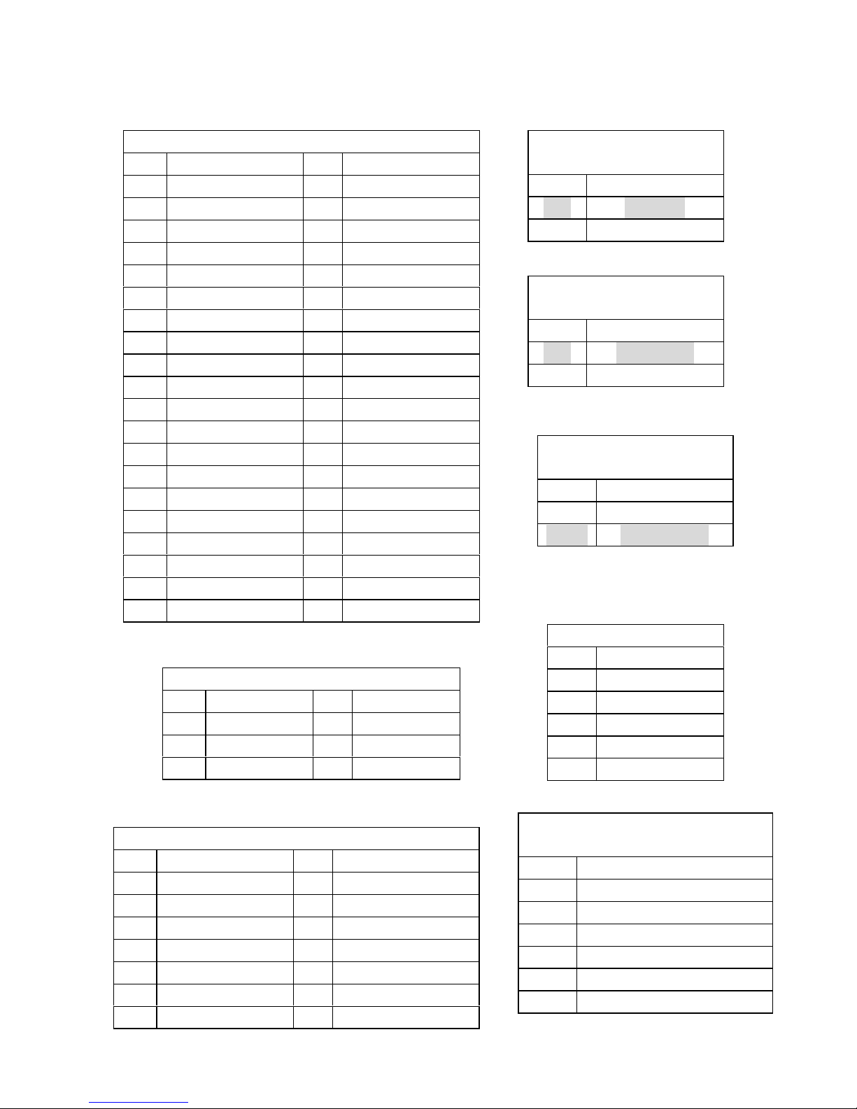
Jumpers setting and Connectors
JP15: Compact Flash
Mode selcet
JP15 Description
1-2 SLAVE
2-3 MASTER
CN5: TV OUT Connector
PIN Description PIN Description
1 TVSYNC 2 TVY
3 GND 4 TVC
5 GND 6 TVCVBS
CN7: IR Connector
PIN Description
1 VCC5
2 NC
3 IR-RX
4 GND
5 IR-TX
CN14: RS-232/RS-422/RS-485 Connector
PIN Description PIN Description
1 DCD# 2 DSR
3 RXD 4 RTS
5 TXD 6 CTS
7 DTR# 8 RI
9 GND 10 NC
11 TXD485+ 12 TXD485#
13 RXD485+ 14 RXD485#
JP16: AT/ATX Power
Mode Select
JP16 Description
short AT Mode
open ATX Mode
CN9: IDE Connector(Bule)(IDE40)
PIN Description PIN Description
1 RESET# 2 GND
3 D7 4 D8
5 D6 6 D9
7 D5 8 D10
9 D4 10 D11
11 D3 12 D12
13 D2 14 D13
15 D1 16 D14
17 D0 18 D15
19 GND
21 DRQ 22 GND
23 IOW# 24 GND
25 IOR# 26 GND
27 RDY 28 GND
29 ACK# 30 GND
31 INTR 32 NC
33 A1 34 CABLE_ID
35 A0 36 A2
37 HD_SELECT 0 38 HD_SELECT 1
39 ACTIVE# 40 GND
CN32: 6-pin Header
Keyboard/Mouse Connector
PIN Description
1 VCC5
2 Mouse_Date
3 Mouse_Clock
4 Keyboard_ Date
5 Keyboard_ Clock
6 GND
JP15: Compact Flash
Mode selcet
JP15 Description
1-2 MASTER
2-3 SLAVE
* For Intel.Chipset mode
 Loading...