

Page 1

USER MANUAL
TCM 515 – ENOCEAN TRANSCEIVER GATEWAY MODULE
© 2020 EnOcean | www.enocean.com F-710-017, V1.0 TCM 515 User Manual | v1.17 | December 2020 | Page 1/115
Patent protected:
WO98/36395, DE 100 25 561, DE 101 50 128,
WO 2004/051591, DE 103 01 678 A1, DE 10309334,
WO 04/109236, WO 05/096482, WO 02/095707,
US 6,747,573, US 7,019,241
Observe precautions! Electrostatic sensitive devices!
TCM 515
EnOcean Transceiver Gateway Module
Page 2

USER MANUAL
TCM 515 – ENOCEAN TRANSCEIVER GATEWAY MODULE
© 2020 EnOcean | www.enocean.com F-710-017, V1.0 TCM 515 User Manual | v1.17 | December 2020 | Page 2/115
REVISION HISTORY
The following major modifications and improvements have been made to this document:
Version
Author
Reviewer
Date
Major Changes
1.0
MKA
MK, CB
12.05.2017
First public release
1.1
MKA
MKA
22.05.2017
Added detailed antenna information
1.2
MKA
MH, MK
22.06.2017
Added receiver class due to RED requirement
1.3
OS
MKA
08.08.2017
Added FCC grant and regulatory information
for FCC and ISED; Added maximum input
power
1.4
MKA
MKA
31.08.2017
Added Tape & Reel specification
1.5
MKA
MKA
19.09.2017
Added detailed description of filtering functionality
1.6
MKA
MKA
25.10.2017
Added maximum number of filters
1.7
MKA
MKA
10.01.2018
Extensive update for production version.
Added detailed description of telegram processing, security operations and noise filtering.
1.8
MKA
MKA
30.01.2018
Added product revision history
Added maximum input power and RSSI accuracy. Added current during start-up.
1.9
MKA
MKA
30.04.2018
Added DA-7 to product history
1.10
MKA
MKA
31.07.2018
Added DB-8 to product history, extended description of ESP3 interface, telegram filtering
and BaseID functionality
1.11
MKA
MKA
08.01.2019
Added application info for SAW circuit
1.12
MKA
MKA
05.02.2019
Added note regarding test points and regarding RLC storage.
1.13
MKA
MKA
08.08.2019
Update with new features in product version
DB-09
1.14
MKA
MKA
28.01.2020
Corrected list of supported secure RORG
1.15
MKA
MKA
18.03.2020
Added information about ESP3 command for
transmission
1.16
MKA
MKA
31.07.2020
Added new features in product version DC,
Added introduction to EnOcean radio in Appendix A and EnOcean security in Appendix B
1.17
MKA
MKA
08.12.2020
Added PCB parameters for whip antenna
Added description of product label
Published by EnOcean GmbH, Kolpingring 18a, 82041 Oberhaching, Germany
www.enocean.com, info@enocean.com, phone +49 (89) 6734 6890
© EnOcean GmbH, All Rights Reserved
Page 3

USER MANUAL
TCM 515 – ENOCEAN TRANSCEIVER GATEWAY MODULE
© 2020 EnOcean | www.enocean.com F-710-017, V1.0 TCM 515 User Manual | v1.17 | December 2020 | Page 3/115
Disclaimer
This user manual describes the type of component and shall not be considered as assured
characteristics. No responsibility is assumed for possible omissions or inaccuracies. Circuitry
and specifications are subject to change without notice. For the latest product specifications,
refer to the EnOcean website: http://www.enocean.com.
As far as patents or other rights of third parties are concerned, liability is only assumed for
modules, not for the described applications, processes and circuits.
EnOcean does not assume responsibility for use of modules described and limits its liability
to the replacement of modules determined to be defective due to workmanship. Devices or
systems containing RF components must meet the essential requirements of the local legal
authorities.
The modules must not be used in any relation with equipment that supports, directly or
indirectly, human health or life or with applications that can result in danger for people,
animals or real value.
Components of the modules are considered and should be disposed of as hazardous waste.
Local government regulations are to be observed.
Packing: Please use the recycling operators known to you.
Page 4

USER MANUAL
TCM 515 – ENOCEAN TRANSCEIVER GATEWAY MODULE
© 2020 EnOcean | www.enocean.com F-710-017, V1.0 TCM 515 User Manual | v1.17 | December 2020 | Page 4/115
TABLE OF CONTENT
1 General description ........................................................................................ 8
1.1 Basic functionality ......................................................................................... 8
1.2 Technical data ............................................................................................... 9
1.3 Physical dimensions ..................................................................................... 10
1.4 Environmental conditions ............................................................................. 10
1.5 Packaging information .................................................................................. 10
1.6 Ordering information ................................................................................... 10
2 Functional information ................................................................................. 11
2.1 High-level functionality ................................................................................ 11
2.2 Functional states ......................................................................................... 12
2.3 Device interface .......................................................................................... 13
2.3.1 Pin-out ............................................................................................... 13
2.4 Power supply .............................................................................................. 14
2.5 Antenna ..................................................................................................... 14
2.6 UART interface ............................................................................................ 14
2.7 Reset ......................................................................................................... 15
2.8 Test interface (TP1, TP2, TP3) ....................................................................... 15
2.9 Product label ............................................................................................... 15
2.9.1 QR code ............................................................................................. 16
3 Power-up, initialization and system operation ................................................. 17
3.1 Typical operation sequence for transmit and receive mode ............................... 17
3.2 Typical operation sequence for transmit-only mode ......................................... 18
4 Telegram reception ...................................................................................... 19
4.1 Telegram reception flow ............................................................................... 19
4.2 Telegram filtering ........................................................................................ 20
4.2.1 Filter type ........................................................................................... 21
4.2.2 Filter value .......................................................................................... 21
4.2.3 Filter condition .................................................................................... 22
4.2.4 Filter action ......................................................................................... 22
4.2.5 Filter combination ................................................................................ 23
4.2.6 Filter definition .................................................................................... 23
4.2.7 Filter enabling ..................................................................................... 24
4.2.8 Filter reading ....................................................................................... 25
4.2.9 Filter deletion ...................................................................................... 26
4.2.10 Filter examples .................................................................................... 27
4.2.10.1 Forwarding (ESP3 to host) filter examples ............................................ 27
4.2.10.2 Repeater filter examples .................................................................... 28
4.3 RADIO_ERP1 packet for received telegrams .................................................... 29
4.4 RADIO_ERP2 packet for received telegrams (TCM 515U only) ........................... 30
4.5 Wait for RX maturity time ............................................................................. 31
4.6 Transparent mode ....................................................................................... 32
Page 5

USER MANUAL
TCM 515 – ENOCEAN TRANSCEIVER GATEWAY MODULE
© 2020 EnOcean | www.enocean.com F-710-017, V1.0 TCM 515 User Manual | v1.17 | December 2020 | Page 5/115
4.7 RSSI test mode ........................................................................................... 33
5 Telegram transmission ................................................................................. 35
5.1 Transmission flow ........................................................................................ 35
5.2 RADIO_ERP1 packet for telegram transmission ............................................... 36
5.3 RADIO_ERP2 packet for telegram transmission (TCM 515U only) ....................... 37
5.4 RADIO_MESSAGE packet for telegram transmission ......................................... 38
5.5 Using Base ID for transmission ..................................................................... 39
5.6 Duty cycle limit ........................................................................................... 40
5.6.1 Determining available transmission time ................................................. 41
5.7 Transmit-only mode .................................................................................... 42
6 Telegram repeating ..................................................................................... 43
6.1 Configuration of telegram repeating ............................................................... 44
7 Security processing ..................................................................................... 45
7.1 TCM 515 security architecture ....................................................................... 45
7.2 Telegram processing flow ............................................................................. 46
7.3 Secure link table ......................................................................................... 47
7.3.1 Secure link table parameters ................................................................. 48
7.4 Telegram encryption and decryption .............................................................. 50
7.5 Telegram authentication ............................................................................... 50
7.6 RLC support ................................................................................................ 51
7.6.1 Explicit and implicit rolling code support ................................................. 51
7.6.2 RLC roll-over ....................................................................................... 52
7.6.3 RLC backup ......................................................................................... 53
7.7 Teach-in of secure devices ............................................................................ 54
7.7.1 Security parameters ............................................................................. 54
7.7.1.1 Security key ..................................................................................... 54
7.7.1.2 RLC ................................................................................................. 54
7.7.2 Secure teach-in procedure .................................................................... 55
7.7.3 Teach-in of secure devices with secure teach-in telegram ......................... 55
7.7.3.1 Transmission of a secure teach-in telegram .......................................... 55
7.7.3.2 Reception of a secure teach-in telegram (Teach-in mode) ...................... 56
7.7.3.3 Handling of secure teach-in telegrams if teach-in mode is not active ....... 57
7.7.4 Teach-in of secure devices using ESP3 ................................................... 58
7.8 Reporting of security-related events .............................................................. 60
8 Low power sleep mode ................................................................................. 61
9 ESP3 interface ............................................................................................ 62
9.1 ESP3 physical interface ................................................................................ 62
9.2 ESP3 packet structure .................................................................................. 63
9.3 Supported ESP3 commands .......................................................................... 64
9.4 Persistent versus not persistent configuration settings ..................................... 66
10 Remote management ................................................................................... 67
11 Device integration ....................................................................................... 68
11.1 Recommended PCB Footprint ................................................................... 68
Page 6

USER MANUAL
TCM 515 – ENOCEAN TRANSCEIVER GATEWAY MODULE
© 2020 EnOcean | www.enocean.com F-710-017, V1.0 TCM 515 User Manual | v1.17 | December 2020 | Page 6/115
11.2 Device outline ........................................................................................ 69
11.3 Soldering information .............................................................................. 70
11.4 Packaging information ............................................................................. 71
11.5 Layout recommendations ......................................................................... 72
11.6 Power supply requirements ...................................................................... 73
11.7 Using an SAW Filter with TCM 515 (868 MHz version only) .......................... 73
11.8 Low noise design considerations ............................................................... 74
11.9 Suggested Reset circuit ........................................................................... 75
11.10 Test interface ...................................................................................... 76
11.11 Identifying the TCM 515 product revision ................................................ 76
12 Antenna options .......................................................................................... 77
12.1 Antenna options for 868 MHz (European Union) ......................................... 77
12.1.1 Whip antenna ...................................................................................... 78
12.2 Antenna options for 902 MHz (US / Canada) .............................................. 79
12.2.1 Whip antenna ...................................................................................... 79
12.2.2 Helical antenna .................................................................................... 79
12.2.3 Chip antenna (Supplier: Mitsubishi Material, Type AM11DP-ST01T) ............ 80
12.2.4 Dipole antenna (ANT-916-CW-HWR-RPS)................................................ 81
13 Application information ................................................................................ 82
13.1 Transmission range ................................................................................. 82
13.2 Maximum input power ............................................................................. 83
13.3 RSSI reporting ....................................................................................... 83
14 Regulatory information ................................................................................. 84
14.1 RED (European Union) ............................................................................ 84
14.1.1 RED Attestation of Conformity for TCM 515 ............................................. 85
14.2 FCC (United States) ................................................................................ 86
14.2.1 FCC Grant Of Equipment Authorization ................................................... 86
14.2.2 FCC Usage Conditions .......................................................................... 87
14.2.3 OEM Requirements .............................................................................. 88
14.2.4 Module Activation ................................................................................ 89
14.3 ISED (former Industry Canada) Certification .............................................. 90
14.3.1 ISED Technical Acceptance Certificate .................................................... 90
14.3.2 ISED Usage Conditions ......................................................................... 91
14.4 Repeater Function (FCC/IC) ..................................................................... 92
15 References ................................................................................................. 93
16 Product history ............................................................................................ 94
A. Introduction to EnOcean radio protocol .......................................................... 95
A.1 ERP1 telegram format .................................................................................. 95
A.2 ERP2 telegram format .................................................................................. 96
A.3 Subtelegrams ............................................................................................. 96
A.3.1 Subtelegram timing ................................................................................. 97
A.3.2 TX maturity time ..................................................................................... 98
A.3.3 RX maturity time ..................................................................................... 98
A.4 Addressing ................................................................................................. 99
A.4.1 Address types ......................................................................................... 99
A.4.2 EURID (Radio ID) ...................................................................................... 100
A.4.3 Broadcast ID ............................................................................................. 100
A.4.4 Base ID .................................................................................................... 100
Page 7

USER MANUAL
TCM 515 – ENOCEAN TRANSCEIVER GATEWAY MODULE
© 2020 EnOcean | www.enocean.com F-710-017, V1.0 TCM 515 User Manual | v1.17 | December 2020 | Page 7/115
A.5 Data payload ............................................................................................ 101
A.5.1 EnOcean Equipment Profiles (EEP) structure ............................................. 101
A.5.2 Common RORG ..................................................................................... 102
A.5.3 Data payload size .................................................................................. 103
A.6 Telegram chaining ..................................................................................... 103
A.6.1 Telegram chaining for broadcast telegrams ............................................... 104
A.6.2 Telegram chaining for addressed telegrams (ADT) ..................................... 104
A.6.3 Telegram chaining for secure telegram (SEC_CDM) ................................... 105
A.6.4 Telegram chaining for addressed secure telegram (ADT SEC_CDM) ............. 106
B. Introduction to EnOcean security protocol .................................................... 107
B.1 Goals of secure radio communication ........................................................... 107
B.2 Telegram encryption .................................................................................. 108
B.3 Telegram authentication ............................................................................. 108
B.4 Replay protection ...................................................................................... 110
B.4.1 RLC and security key in bi-directional communication ................................ 112
B.4.2 RLC synchronization between sender and receiver ..................................... 113
B.5 Secure telegram types ............................................................................... 114
B.5.1 Secure teach-in telegram ....................................................................... 114
B.5.1.1 Teach-in Info ............................................................................................ 115
B.5.1.2 Security level format (SLF) ......................................................................... 115
Page 8

USER MANUAL
TCM 515 – ENOCEAN TRANSCEIVER GATEWAY MODULE
© 2020 EnOcean | www.enocean.com F-710-017, V1.0 TCM 515 User Manual | v1.17 | December 2020 | Page 8/115
1 General description
1.1 Basic functionality
TCM515 is an addition to the existing TCM 300 / 310 / 320 transceiver module family consisting of the following products:
◼ TCM 515
868.3 MHz ASK, EnOcean Radio Protocol version 1, main market Europe
◼ TCM 515U
902.875 MHz FSK, EnOcean Radio Protocol version 2, main market US and Canada
The term “TCM 515” in this document refers to all members of the TCM 515 family unless
noted differently.
TCM 515 products are limited to OEM installation ONLY.
TCM 515 is optimized for application requiring smallest possible size and integrated security
handling such as line-powered actuators or controllers. For applications requiring highest
radio performance - such as gateways or access points covering larger areas – consider using
TCM 310 which provides the highest possible sensitivity and noise immunity due to an integrated SAW filter.
TCM 515 provides a radio link between EnOcean radio devices and an external host connected
via UART interface using the standardized EnOcean Serial Protocol V3 (ESP3) communication
protocol.
TCM 515 receives and transmits radio telegrams based on a 50 Ohm or whip antenna connected to the host PCB. It forwards received radio telegrams to an external host processor
or host PC via the ESP3 interface. Messages received from an external host via the ESP3
interface will be transmitted by TCM 515 as EnOcean radio telegrams according to the chosen
frequency.
TCM 515 is implemented as 31 pin reflow-solderable module with optimized form factor for
size constrained applications. It is not pin compatible with existing TCM 310 products. Figure
1 below shows TCM 515.
Figure 1 – TCM 515
This document describes the features of TCM 515 (868.3 MHz ERP1) and TCM 515U (902.875
MHz ERP2).
In addition, this document provides an introduction to EnOcean radio networks in Appendix
A and an introduction to EnOcean security architecture in Appendix B.
Page 9

USER MANUAL
TCM 515 – ENOCEAN TRANSCEIVER GATEWAY MODULE
© 2020 EnOcean | www.enocean.com F-710-017, V1.0 TCM 515 User Manual | v1.17 | December 2020 | Page 9/115
1.2 Technical data
Antenna
50 Ohm whip antenna (connected at host board)
Supported Radio Frequencies
TCM 515: 868.3 MHz ASK
TCM 515U: 902.875 MHz FSK
Data Rate
125 kbps
Receiver Sensitivity
(1)
TCM 515: 868.3 MHz ASK: -92 dBm
TCM 515U: 902.875 MHz FSK: -98 dBm
Maximum Input Power
(1) (2)
-17 dBm (for product version DC)
Receiver Blocking Performance
Class 2 according to EN 300 220-1
Radiated RF Immunity
3 V / m according to EN 301 489-3
Transmit Power
TCM 515: 868.3 MHz ASK: +10 dBm
TCM 515U: 902.875 MHz FSK: +1 dBm
Supply Voltage (min / max / typ)
2.0 V / 3.6 V / 3.3 V
Supply Current RX State
25 mA
Supply Current TX State
(3)
25 mA
Supply Current Idle State
(4)
5 mA
Supply Current Sleep Mode
0.05 mA
Power-up to Ready State Timing
50 ms
Ready State to RX State Delay
(5)
200 ms (default setting, adjustable via ESP3)
Supply Current between Power-up and RX
12 mA
TX to RX switching time
(6)
< 1 ms
Serial Interface To Host
UART according to ESP3 Standard (TURBO option)
Note: All figures are typical values at 25°C unless otherwise specified
Note 1: Sensitivity and Maximum Input Power figures are based on 0.1% telegram error rate for the combination
of 3 received sub-telegrams
Note 2: Maximum Input Power is -17 dBm for product revision DC onwards. For previous revisions, it is -23 dBm
Note 3: ASK modulation encodes the bit status (0 or 1) using different radio power levels where 0 is encoded with
a high-power level and 1 with a low power level. The TX current therefore depends on the ration between
bits with the value 0 and bits with the value 1 in the bit stream. The figure given here is for a PN9 sequence.
Note 4: Idle Mode is used when TCM 515 operates in transmit-only mode while no telegram is transmitted.
Transmit-only mode is supported in TCM 515 starting with product revision DC.
Note 5: During start-up, TCM 515 waits for a configurable additional delay before transitioning to RX state
to allow for power supply stabilization and start-up of the external host.
The default value for this delay is 200 ms; this is adjustable via ESP3
Note 6: TX to RX switch over time is measured from the transmission of the last bit (end of frame) of a radio frame
until the receiver is ready to receive the first bit (preamble) of a radio frame
Page 10

USER MANUAL
TCM 515 – ENOCEAN TRANSCEIVER GATEWAY MODULE
© 2020 EnOcean | www.enocean.com F-710-017, V1.0 TCM 515 User Manual | v1.17 | December 2020 | Page 10/115
1.3 Physical dimensions
Module Dimensions
19.0 mm x 14.7 mm x 3.0 mm (all +- 0.3 mm)
Module Weight
1 g
1.4 Environmental conditions
Operating Temperature
-40°C ... +85°C
Storage Temperature
-40°C ... +85°C
Humidity
0% to 95% r.h. (non-condensing)
1.5 Packaging information
Packaging Unit / Method 250 units / Tape and reel
1.6 Ordering information
Type
Ordering Code
TCM 515
TCM 515U
S3003-K515
S3053-K515
Page 11
USER MANUAL
TCM 515 – ENOCEAN TRANSCEIVER GATEWAY MODULE
© 2020 EnOcean | www.enocean.com F-710-017, V1.0 TCM 515 User Manual | v1.17 | December 2020 | Page 11/115
2 Functional information
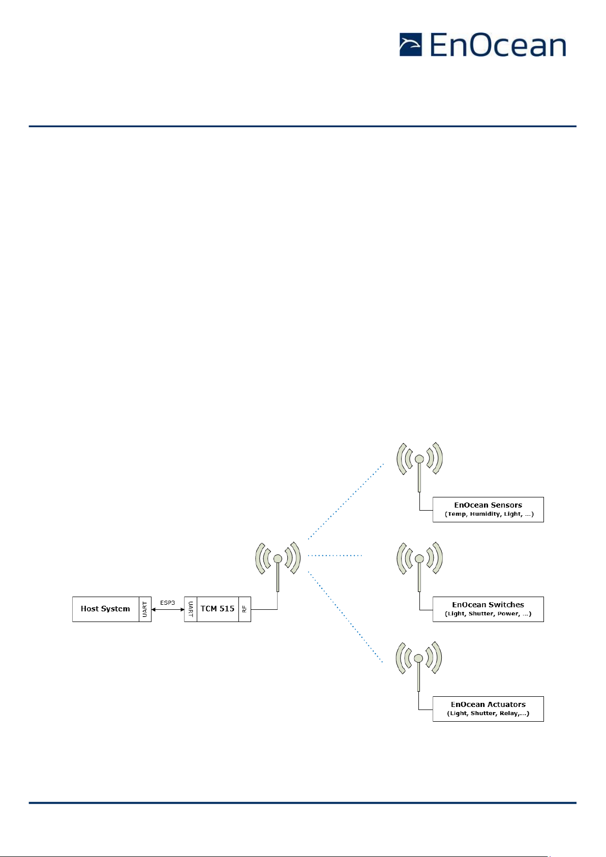
2.1 High-level functionality
TCM 515 is a fully integrated radio transceiver family which enables communication with
other devices implementing the EnOcean Radio Protocol (ERP).
TCM 515 uses EnOcean Radio Protocol 1 as described in the EnOcean Radio Protocol 1 (ERP1)
specification [2] while TCM 515U and TCM 515J use EnOcean Radio Protocol version 2 as
described in the EnOcean Radio Protocol 2 (ERP2) specification [3].
TCM 515 is used to exchange (send and / or receive) radio telegrams with external sensors,
switches or actuators.
TCM 515 is connected to an external host which for instance could be a microprocessor, a
controller or a gateway via the EnOcean Serial Protocol v3 (ESP3) interface. ESP3 commands
are listed within this document for information purposes only; for details about ESP3 commands refer to the ESP3 specification [1].
Figure 2 below shows the integration of TCM 515 into a typical system environment.
Figure 2 – TCM 515 system environment
Page 12
USER MANUAL
TCM 515 – ENOCEAN TRANSCEIVER GATEWAY MODULE
© 2020 EnOcean | www.enocean.com F-710-017, V1.0 TCM 515 User Manual | v1.17 | December 2020 | Page 12/115
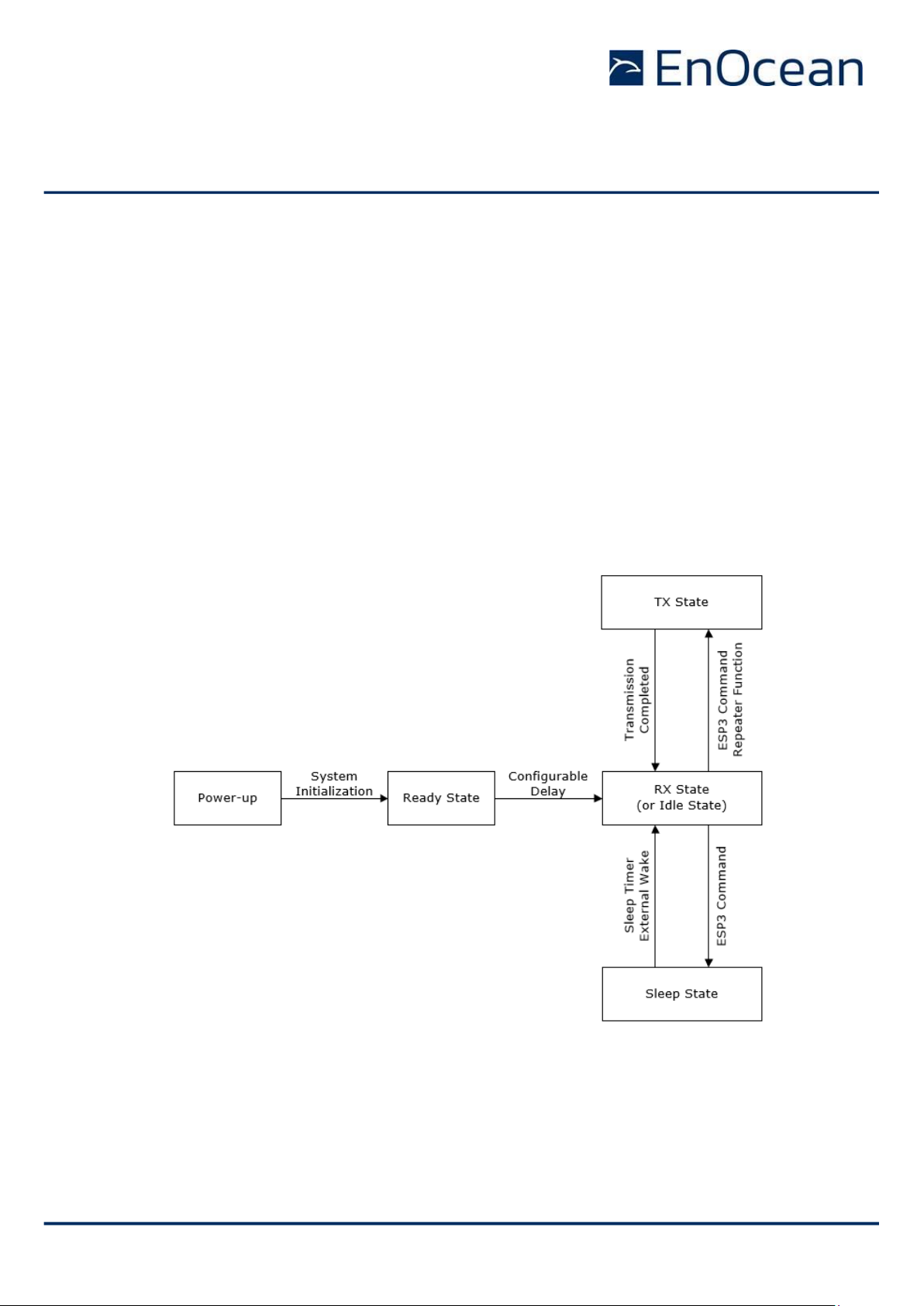
2.2 Functional states
TCM 515 implements the following functional states:
◼ Power-up and system initialization (with user-configurable delay)
This state is described in chapter 3
◼ RX state (telegram reception with security processing, filtering, repeating as required)
This state is described in chapter 4
◼ TX state (telegram transmission with security processing as required)
This state is described in chapter 5
◼ Sleep state (low power state to conserve energy)
This state is described in chapter 8
The transition between these functional states is shown in Figure 3 below.
Figure 3 – TCM 515 functional states
Note that starting with revision DC-10 it is possible to configure TCM 515 to operate as
transmit-only device which disables receive functionality. If TCM 515 is configured to operate
as transmit-only device, then RX state is replaced by Idle state where TCM 515 will wait for
ESP3 commands. Transmit-only functionality is described in chapter 5.7.
Page 13
USER MANUAL
TCM 515 – ENOCEAN TRANSCEIVER GATEWAY MODULE
© 2020 EnOcean | www.enocean.com F-710-017, V1.0 TCM 515 User Manual | v1.17 | December 2020 | Page 13/115
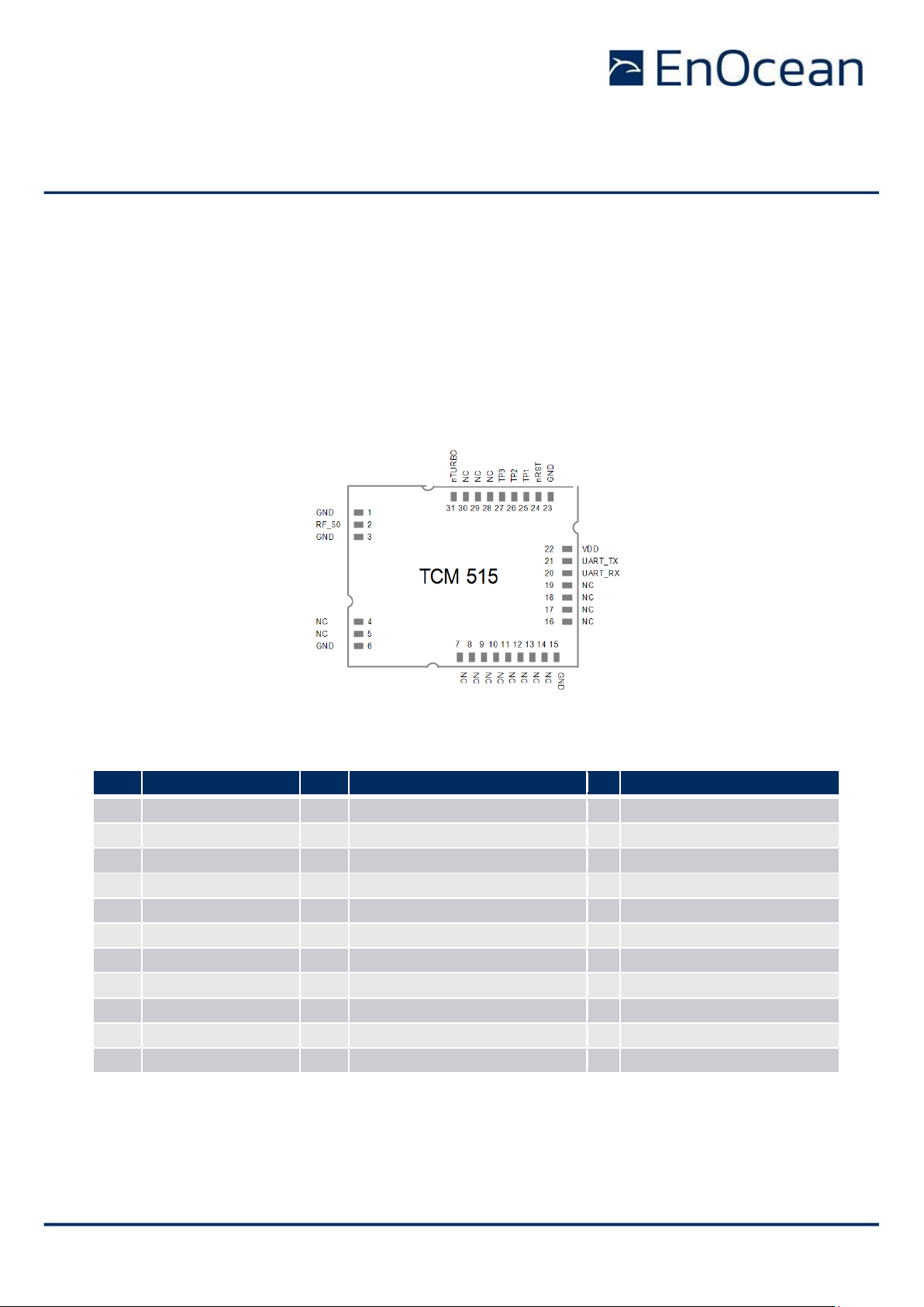
2.3 Device interface
TCM 515 implements a 31 pin reflow-solderable interface. Solder mask data is available on
request from EnOcean.
2.3.1 Pin-out
The pin assignment (as seen from the top of the TCM 515 device) is shown in Figure 4 below.
Solder mask and mechanical data is available from EnOcean.
Figure 4 – TCM 515 device interface
Table 1 below summarizes the signal assignment.
PIN
NAME
PIN
NAME
PIN
NAME
1
GND
12
NC
23
GND 2 RF_50 (50Ω antenna)
13
NC
24
nRESET (Reset input, active low)
3
GND
14
NC
25
TP1 (Test Interface)
4
NC
15
GND
26
TP2 (Test Interface)
5
NC
16
NC
27
TP3 (Test Interface)
6
GND
17
NC
28
NC
7
NC
18
NC
29
NC
8
NC
19
NC
30
NC
9
NC
20
UART_RX (Input to TCM 515)
31
nTURBO (UART speed, active low)
10
NC
21
UART_TX (Output from TCM 515)
11
NC
22
VDD
Table 1 - TCM 515 pin assignment
Signals marked with “NC” are reserved for production test and future device variants and
must not be connected in the design.
Page 14

USER MANUAL
TCM 515 – ENOCEAN TRANSCEIVER GATEWAY MODULE
© 2020 EnOcean | www.enocean.com F-710-017, V1.0 TCM 515 User Manual | v1.17 | December 2020 | Page 14/115
2.4 Power supply
TCM 515 is supplied by the VDD and GND Pins and supports a supply voltage range between
2.0 V and 3.6 V. For best radio performance it is very important to minimize noise on the
supply voltage lines. Please see chapter 11.5 and 11.6.
If TCM 515 is operated close to the minimum supply voltage of 2.0 V then care has to
be taken in the power supply design to ensure that the supply voltage does not drop
to below 2.0 V during load transients such as start-up or wake-up from Sleep state.
2.5 Antenna
TCM 515 receives and transmits data based on a 50Ω whip antenna connected to its RF_50
input (Pin 2). Please see chapter 12.
2.6 UART interface
TCM 515 communicates with the external host using the standard ESP3 serial (UART) interface based on the signals UART_TX (Pin 21, direction from TCM 515 to external host) and
UART_RX (Pin 20, direction from external host to TCM 515).
It is strongly recommended that the PCB design provides the ability to connect to
these signals – e.g. by means of providing suitable test point pads on the PCB - for
the purpose of analysis, debug and firmware update.
The default interface speed of the ESP3 interface is 57600 bit per second and data is transmitted using 8 data bits, 1 STOP bit and no parity (8N1).
It is possible to select faster communication speeds during operation using the ESP3
CO_SET_BAUDRATE command (see chapter 9.1). The following interface speeds are supported by TCM 515:
◼ 57600 bit per second
◼ 460800 bit per second
Additionally, it is possible to change the default ESP3 interface speed at power up from
57.600 bit per second to 460.800 bit per second by connecting the nTURBO input (Pin 31,
active low) to Ground.
Subsequent modification of the interface speed during operation using the
CO_SET_BAUDRATE command is always possible irrespective of the state of the TURBO input
pin.
Care should be taken not to select a UART interface speed which cannot be supported
by the connected host processor as this would prevent subsequent communication.
Page 15
USER MANUAL
TCM 515 – ENOCEAN TRANSCEIVER GATEWAY MODULE
© 2020 EnOcean | www.enocean.com F-710-017, V1.0 TCM 515 User Manual | v1.17 | December 2020 | Page 15/115
2.7 Reset
TCM 515 can be reset by pulling the nRESET pin (Pin 24, active low) to Ground. Please see
chapter 11.9 for reset circuit recommendations.
It is strongly recommended that the PCB design provides the ability to connect to this
signal – e.g. by means of providing a suitable test point pad on the PCB - for the
purpose of analysis, debug and firmware update.
2.8 Test interface (TP1, TP2, TP3)
TCM 515 provides a test interface (TP1, TP2 and TP3). The intended use of this interface is
for analysis and debugging of customer products by EnOcean.
It is strongly recommended that customer PCB design provides the ability to connect
external devices to these signals – e.g. by means of providing suitable test point pads
on the PCB - for the purpose of analysis, debug and firmware update.
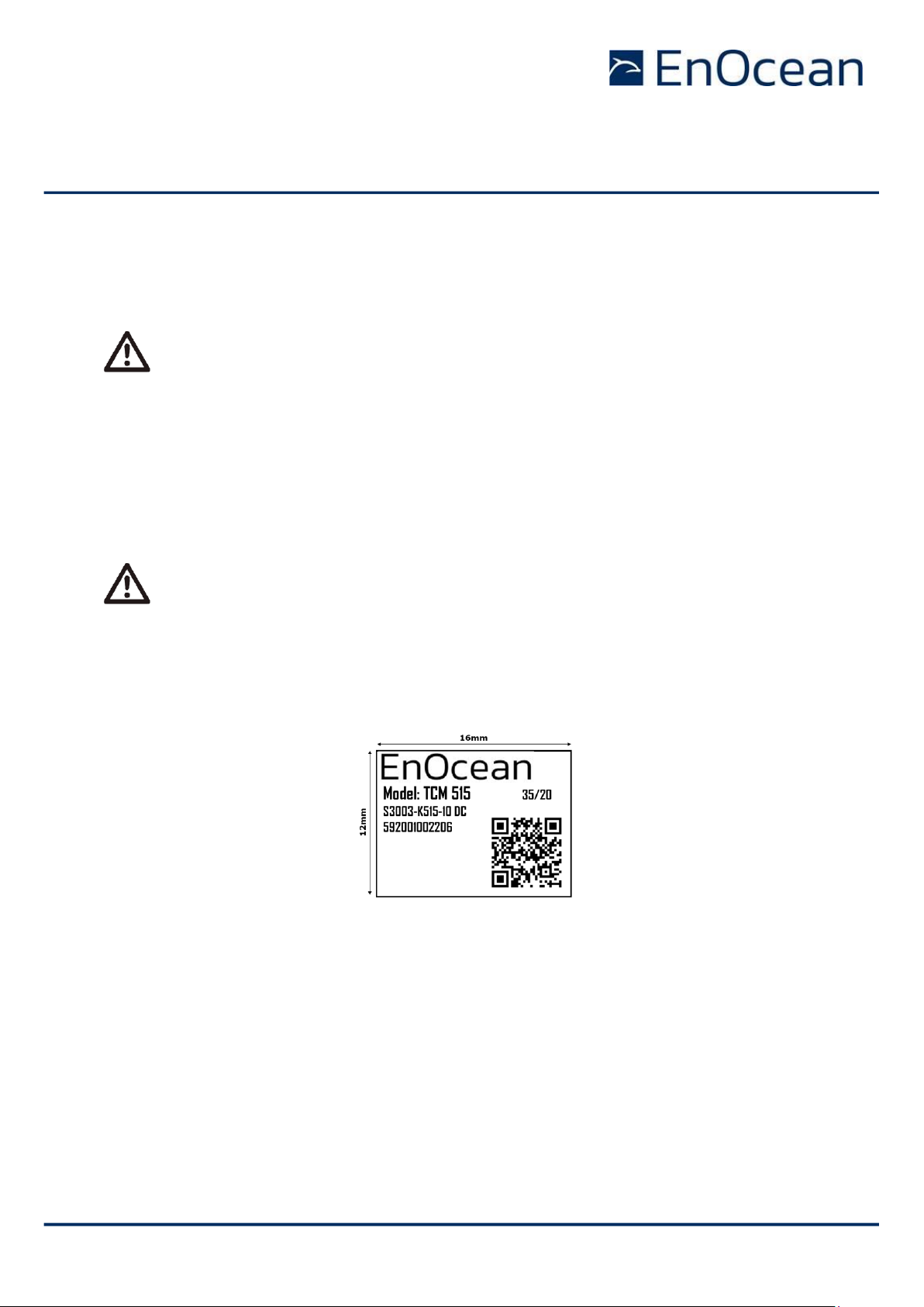
2.9 Product label
Each TCM 515 contains a product label as shown in Figure 5 below.
Figure 5 – TCM 515 product label
The label shown above identifies the following parameters in writing:
◼ Product name (TCM 515)
◼ Order number (S3003-K515)
◼ Product revision (DC-10)
◼ Manufacturing date (week 35, 2020)
◼ Manufacturer traceability code (592001002206)
Page 16

USER MANUAL
TCM 515 – ENOCEAN TRANSCEIVER GATEWAY MODULE
© 2020 EnOcean | www.enocean.com F-710-017, V1.0 TCM 515 User Manual | v1.17 | December 2020 | Page 16/115
2.9.1 QR code
The TCM 515 product label contains an automatically readable QR code in the lower right
corner which encodes certain product parameters according to the ANSI/MH10.8.2-2013
standard as listed in Table 2 below.
Data Identifier
Data Length
(excluding identifier)
Data Content
30S
8 characters (hexadecimal)
EnOcean Radio ID (EURID)
30P
10 characters (alphanumeric)
Ordering Code
2P
4 characters (alphanumeric)
Step Code and Revision
S
14 characters (decimal)
Serial Number (starts with 01)
Table 2 – TCM 515 product QR code structure
Page 17
USER MANUAL
TCM 515 – ENOCEAN TRANSCEIVER GATEWAY MODULE
© 2020 EnOcean | www.enocean.com F-710-017, V1.0 TCM 515 User Manual | v1.17 | December 2020 | Page 17/115
3 Power-up, initialization and system operation
After power-up, TCM 515 executes the following steps:
◼ Initialization of the system
TCM 515 initializes all system components and peripherals.
After that, TCM 515 transitions to Ready state
◼ Wait for pre-configured delay
This delay allows the power supply to stabilize and the external host to initialize the
system. The default value of this delay is 200 ms; this is configurable This delay can
be configured as persistent parameter (maintained after power down) using the ESP3
command CO_WR_STARTUP_DELAY.
After that, TCM 515 is in ready for operation depending on the selected TCM 515 operation
mode (transmit and receive mode or transmit-only mode).
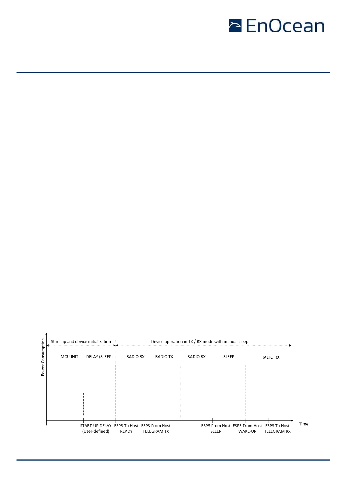
3.1 Typical operation sequence for transmit and receive mode
The default configuration of TCM 515 is transmit and receive mode. In this mode, TCM 515
is continuously scan for EnOcean radio telegrams in RX state unless it receives a request
from the host to transmit a telegram.
If TCM 515 receives a valid EnOcean radio telegram, then it will process this as described in
chapter 4 and forward it to the host via ESP3.
If TCM 515 receives a request from the host to transmit a telegram, then it will transition to
TX state and transmit the telegram as described in chapter 5. After that, it will automatically
transition back to RX state and continue to scan for EnOcean radio telegrams.
Figure 6 below shows a typical operation sequence for transmit and receive mode with manual sleep entry and exit.
Figure 6 – Operation sequence for transmit and receive mode with manual sleep
Page 18
USER MANUAL
TCM 515 – ENOCEAN TRANSCEIVER GATEWAY MODULE
© 2020 EnOcean | www.enocean.com F-710-017, V1.0 TCM 515 User Manual | v1.17 | December 2020 | Page 18/115
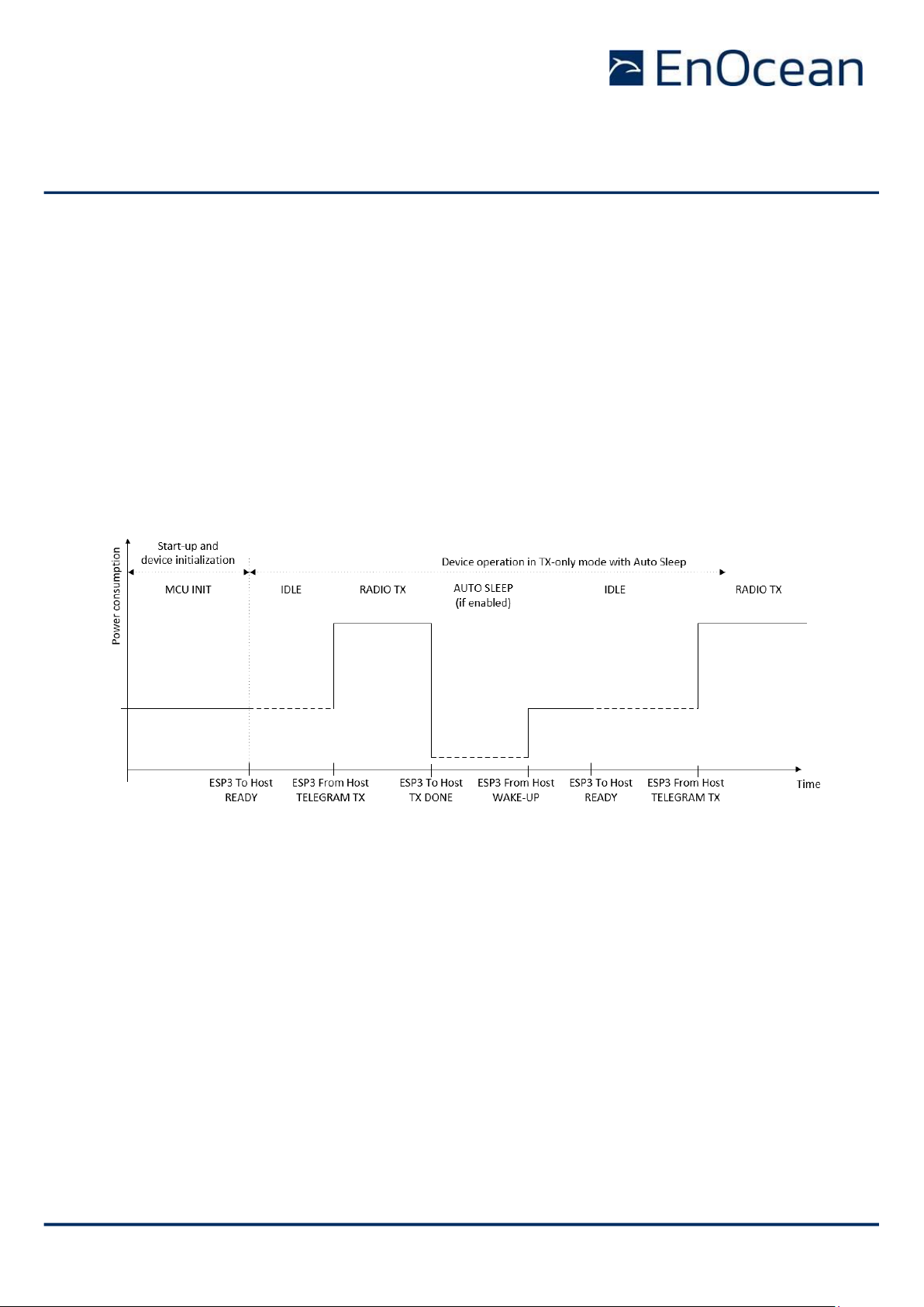
3.2 Typical operation sequence for transmit-only mode
In transmit-only mode, TCM 515 will wait in Idle state until an ESP3 command from the host
requesting the transmission of a telegram has been received. It will then transmit the telegram as described in chapter 5 and inform the host once the transmission of a telegram has
been completed.
After completion of the telegram transmission, TCM 515 will either transition back to Idle
state waiting for the next command from the host (default configuration) or automatically
enter Sleep state waiting for a wake-up via ESP3 command (Auto Sleep configuration).
Figure 7 below shows a typical operation sequence for transmit-only mode with automatic
sleep entry (Auto Sleep). See chapter 5.7 for a detailed description of transmit-only mode.
Figure 7 – Operation sequence for transmit-only mode with Auto Sleep
Page 19

USER MANUAL
TCM 515 – ENOCEAN TRANSCEIVER GATEWAY MODULE
© 2020 EnOcean | www.enocean.com F-710-017, V1.0 TCM 515 User Manual | v1.17 | December 2020 | Page 19/115
4 Telegram reception
After start-up, TCM 515 will enter receive state unless TX-only mode is active as discussed
in chapter 5.7.
4.1 Telegram reception flow
While in receive state, TCM 515 will wait for valid EnOcean radio telegrams and then performs
the following functions:
◼ RX telegram processing
Received data bitstream is processed (detection and removal of preamble, start of
frame, end of frame and redundant bits, CRC check, subtelegram merge) and formatted as EnOcean radio telegrams
◼ Repeater handling
Received telegrams are checked if they should be repeated based on the repeater
mode configured at TCM 515 (L1 Repeater, L2 Repeater, Selective Repeater) and the
repeater information reported as part of the radio telegram. If the received telegram
should be repeated, then it will be inserted into the transmission queue. See chapter
5.7 for details on the repeater functionality.
◼ Telegram filtering
Received telegrams can be classified according to user-defined characteristics so that
only telegrams matching these characteristics will be processed and forwarded to the
external host via the ESP3 interface. See chapter 4.2 for details.
◼ Security processing
Telegrams from senders using high security mode can be automatically decrypted and
authenticated according to their security parameters stored in the inbound secure link
table. See chapter 7 for details.
◼ ESP3 formatting and telegram forwarding
Processed telegrams will be formatted as ESP3 packet (RADIO_ERP1 or RADIO_ERP2)
and forwarded to the external host via the ESP3 interface. See chapter 9 for details.
Figure 8 below shows the processing flow for received telegrams.
Figure 8 – Telegram Reception Flow
Page 20

USER MANUAL
TCM 515 – ENOCEAN TRANSCEIVER GATEWAY MODULE
© 2020 EnOcean | www.enocean.com F-710-017, V1.0 TCM 515 User Manual | v1.17 | December 2020 | Page 20/115
4.2 Telegram filtering
By default, TCM 515 will forward all valid telegrams received by it (including such that are
addressed to a different receiver) to the host via its ESP3 interface.
Additionally, TCM 515 will repeat all received telegrams if repeating is enabled.
Filtering allows the host to configure via the ESP3 interface conditions based on which telegrams are forwarded to the host or repeated. Telegram filtering is based on the following
parameters:
◼ Filter type
The filter type defines based on what property TCM 515 should evaluate in received
telegrams, e.g. if it should check the source address, the destination address, the
telegram type or the signal strength
◼ Filter value
The filter value defines the reference value against which TCM 515 will compare the
property of the received telegram
◼ Filter condition
The filter condition defines the desired relation between the defined filter value and
the corresponding property of the received telegram.
For the case of source address, destination address and RORG, the filter condition can
be Equal (e.g. the source address of received telegram is the same as the defined
filter value) or Not Equal (e.g. the RORG of the received telegram is not the same as
the defined filter value).
For the case of signal strength, the filter condition can be Lower Than Or Equal (the
received signal strength is lower than the defined value or equal to it) or Higher Than
(the received signal strength is higher than the defined value).
◼ Filter action
The filter action defines what TCM 515 should do if the filter condition is true, e.g. if
it should forward the telegram to the host or if it should forward the telegram to the
host and repeat the telegram
◼ Filter combination
The filter combination defines what happens if more than one filter condition is defined
for a specific set filter action, e.g. if the filters controlling telegram forwarding to the
host should be combined in a logic OR fashion or a logic AND fashion.
The following chapters describe these parameters in more detail.
Page 21

USER MANUAL
TCM 515 – ENOCEAN TRANSCEIVER GATEWAY MODULE
© 2020 EnOcean | www.enocean.com F-710-017, V1.0 TCM 515 User Manual | v1.17 | December 2020 | Page 21/115
4.2.1 Filter type
TCM 515 supports the following filter types:
◼ Source EURID Filter
The source EURID (EnOcean Universal Radio ID = EURID of the sender of the telegram) is evaluated.
This filter type can for instance be used in actuators which only accept input from
certain devices (e.g. switches) identified by their EURID
◼ Destination EURID Filter
The destination EURID (EnOcean Universal Radio ID = EURID of the intended receiver
of the telegram) is evaluated.
This filter type can for instance be used by a receiver to not repeat radio telegrams
that are directly addressed to it (and therefore do not need to be received by other
devices).
◼ Telegram Type (RORG) Filter
The telegram type of the received telegram is evaluated.
This filter type can be used for instance be used in actuators which should react only
to switch telegrams (RPS Telegram Type).
◼ Received signal strength (RSSI) Filter
The received signal strength (RSSI) of the received telegram is evaluated.
This filter type can for instance be used during learn-in if an actuator should only
accept teach-in telegrams from devices close to the receiver.
Alternatively, this filter type could also be used in repeaters so that only telegrams
with weak signal strength (low RSSI value) would be repeated in order to limit radio
congestion.
4.2.2 Filter value
The filter value field contains the value against which the corresponding property of the received telegram is compared. The filter value field is 4 byte long and – depending on the
configured filter type - contains the following:
◼ 32 bit Source EURID (radio address of the sender)
◼ 32 bit Destination EURID (radio address of the intended receiver)
◼ 8 bit RORG
The RORG value has to be allocated in the least significant byte and the remaining 3
byte of the value field should be set to 0x000000
◼ 8 bit RSSI
The RSSI value has to be allocated in the least significant byte and the remaining 3
byte of the value field should be set to 0x000000. The absolute value of the desired
RSSI shall be entered, i.e. an RSSI threshold of -80 dBm is desired then the value 80
shall be entered
Page 22

USER MANUAL
TCM 515 – ENOCEAN TRANSCEIVER GATEWAY MODULE
© 2020 EnOcean | www.enocean.com F-710-017, V1.0 TCM 515 User Manual | v1.17 | December 2020 | Page 22/115
4.2.3 Filter condition
TCM 515 supports the following filter conditions for Source ID, Destination ID and RORG:
◼ Is Equal
The value in the received telegram is the same as the defined filter value
◼ Is Not Equal
The value in the received telegram is different from the defined filter value
TCM 515 supports the following filter conditions for signal strength (RSSI):
◼ Is Less Than Or Equal (used instead of the Is Equal condition for RSSI)
If the defined signal strength (RSSI) value is -50 dBm then received telegrams with
signal strength – 50 dBm, -51 dBm, …, -98 dBm will all match this condition. Note
that TCM 515 cannot receive signals with a signal strength below the specified RX
sensitivity.
◼ Is Greater Than (used instead of the Is Not Equal condition for RSSI)
If the defined signal strength (RSSI) value is -50 dBm then received telegrams with
signal strength -49 dBm, -48 dBm, … -17 dBm will all match this condition. Note that
TCM 515 cannot receive signals with a signal strength above the specified maximum
input power.
4.2.4 Filter action
TCM 515 supports two types of filter actions:
◼ Forward the received telegram to the host via ESP3 function
This filter is ignored for the repeater function
◼ Forward the received telegram to the host via ESP3 interface and
Repeat (retransmit) the received telegram if selective repeating is enabled
Note that the filter action for telegram repeating is only considered if the repeater functionality is configured for Selective Repeating as described in chapter 6.1.
Page 23

USER MANUAL
TCM 515 – ENOCEAN TRANSCEIVER GATEWAY MODULE
© 2020 EnOcean | www.enocean.com F-710-017, V1.0 TCM 515 User Manual | v1.17 | December 2020 | Page 23/115
4.2.5 Filter combination
For each of the two actions (telegram forwarding to the host, telegram repeating) it is possible to define one or several filters.
The combination between the defined filters for the same filter action can either be a logical
AND (all filter conditions must be true in order to execute the filter action) or a logical OR
(one of the filter conditions must be true in order to execute the filter action). For the case
of selective repeating, filters with condition / action codes 0x00 and 0x40 will be ignored
when evaluating the defined filters.
TCM 515 support the definition of up to 30 individual filters in total. Attempting to define
more than 30 filters will result in the response 01: RET_ERROR (memory space full).
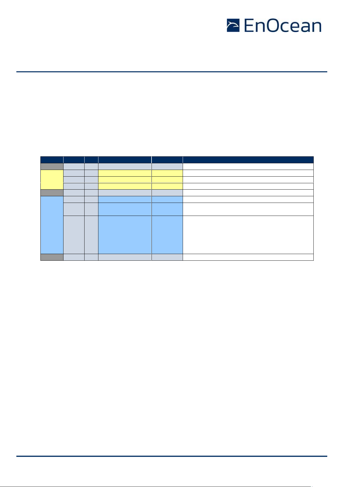
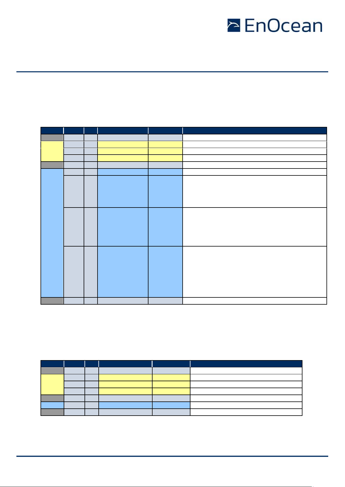
4.2.6 Filter definition
Telegram filters are defined using the CO_WR_FILTER_ADD command as shown in Table 3
below.
Group
Offset
Size
Field
Value hex
Description
- 0 1
Sync. byte
0x55
Header
1
2
Data Length
0x0007
7 bytes
3
1
Optional Length
0x00
0 byte
4
1
Packet Type
0x05
0x05: COMMON_COMMAND
- 5 1
CRC8H
0xnn
Data
6
1
COMMAND Code
0x0B
0x0B: CO_WR_FILTER_ADD
7
1
Filter type
0x00…0x03
Telegram property that will be evaluated
0x00: Source EURID
0x01: Telegram type (RORG)
0x02: Received signal strength (RSSI, in dBm)
0x03: Destination EURID
8
4
Filter value
0xnnnnnnnn
Value to compare against
- Source EURID (4 byte)
- RORG (1 byte)
- Signal strength (1 byte, interpreted as negative
of this value, e.g. 85 means -85 dBm)
- Destination EURID (4 byte)
12
1
Filter condition
and action
0x00
0x80
0x40
0xC0
0x00: Forward to host if condition is false
Ignore this filter for selective repeating
0x80: Forward to host if condition is true
Ignore this filter for selective repeating
0x40: Forward to host if condition is false
Repeat telegram if condition is false
0xC0: Forward to host if condition is true
Repeat telegram if condition is true
-
13
1
CRC8D
0xnn
Table 3 – Syntax for CO_WR_FILTER_ADD
Note that if the filter value is only 8 bit long (for RORG or RSSI filters) then the remaining
bits of the filter value field should bet set to 0x000000.
Page 24
USER MANUAL
TCM 515 – ENOCEAN TRANSCEIVER GATEWAY MODULE
© 2020 EnOcean | www.enocean.com F-710-017, V1.0 TCM 515 User Manual | v1.17 | December 2020 | Page 24/115
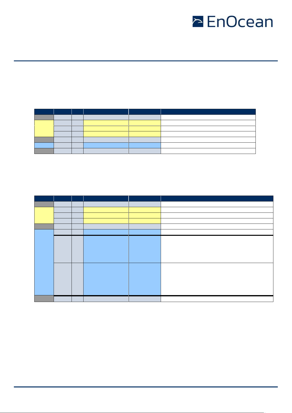
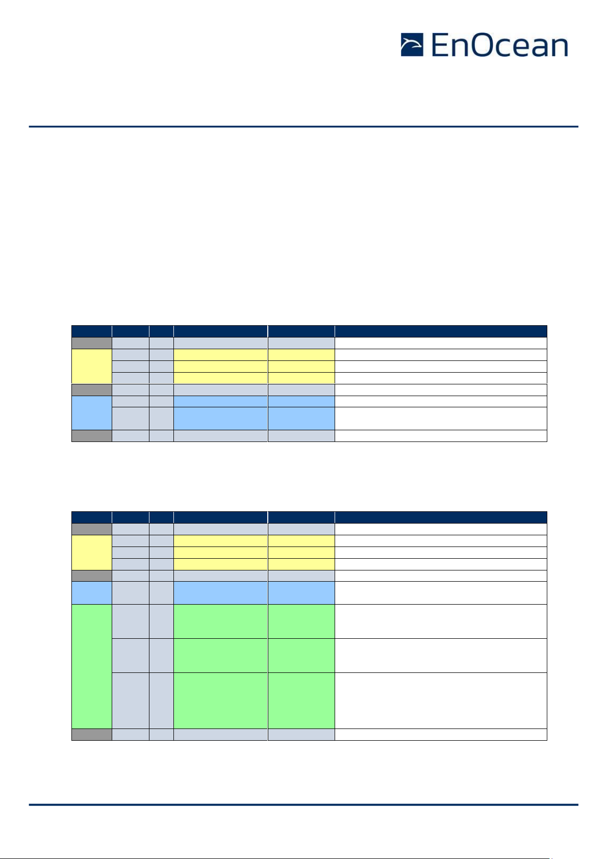
4.2.7 Filter enabling
Once all filters have been defined, the CO_WR_FILTER_ENABLE command shown in Table 4
below has to be used to select the logical relation between the defined filters (logical AND
versus logical OR) and to enable the filtering mechanism for telegram forwarding via ESP3.
Note that the combination between the defined filters can be set independently for the host
filters determining if a received telegram will be forwarded to the host via the ESP3 interface and the repeater filters determining if a received telegram will be repeated.
Group
Offset
Size
Field
Value hex
Description
- 0 1
Sync. byte
0x55
Header
1
2
Data Length
0x0003
3 bytes
3
1
Optional Length
0x00
0 byte
4
1
Packet Type
0x05
0x05: COMMON_COMMAND
- 5 1
CRC8H
0xnn
Data
6
1
COMMAND Code
0x0E
0x0E: CO_WR_FILTER_ENABLE = 14
7
1
Forward Filter
ON/OFF
0x00
0x01
0x00: Forwarding filter disabled
0x01: Forwarding filter enabled
8
1
Filter Operator
0x00
0x01
0x08
0x09
0x00: OR connection between all filters
0x01: AND connection between all filters
0x08: OR connection between host filters
AND connection between repeater filters
0x09: AND connection between host filters
OR connection between repeater filters
- 9 1
CRC8D
0xnn
Table 4 – Syntax for CO_WR_FILTER_ENABLE command
The use of the defined filters for the repeater is enabled separately by means of the
CO_WR_REPEATER command shown in Table 23 in chapter 446.1. There, REP_ENABLE has
to be set to 0x02 to enable selective repeating based on the defined filters.
Note that if a filter is set to be ignored for the cases of repeating (filter condition / action
0x00 or 0x80), then this filter will not be evaluated and the result of the evaluation of the
other filters (not set to be ignored) will not be influenced by it.
Page 25
USER MANUAL
TCM 515 – ENOCEAN TRANSCEIVER GATEWAY MODULE
© 2020 EnOcean | www.enocean.com F-710-017, V1.0 TCM 515 User Manual | v1.17 | December 2020 | Page 25/115
4.2.8 Filter reading
It is possible to read the currently defined filters using the CO_RD_FILTER command shown
in Table 5 below.
Group
Offset
Size
Field
Value hex
Description
- 0 1
Sync. byte
0x55
Header
1
2
Data Length
0x0001
1 byte
3
1
Optional Length
0x00
0 byte
4
1
Packet Type
0x05
0x05: COMMON_COMMAND
- 5 1
CRC8H
0xnn
Data
6
1
COMMAND Code
0x0F
0x0F: CO_RD_FILTER
- 7 1
CRC8D
0xnn
Table 5 – Syntax for CO_RD_FILTER
TCM 515 will reply to the CO_RD_FILTER command with a response containing all defined
filters as shown in below.
Group
Offset
Size
Field
Value hex
Description
- 0 1
Sync. byte
0x55
Header
1
2
Data Length
0xnnnn
1 + 5*f bytes (f = number of filters)
3
1
Optional Length
0x00
0 byte
4
1
Packet Type
0x02
0x02: RESPONSE
- 5 1
CRC8H
0xnn
Data
6
1
Return Code
0x00
0x00: RET_OK
7+5*f
1
Filter type
0xnn
Telegram property that will be evaluated
0x00: Source EURID
0x01: Telegram type (RORG)
0x02: Received signal strength (RSSI, in dBm)
0x03: Destination EURID
8+5*f
4
Filter value
0xnnnnnnnn
Value to compare against
- Source EURID (4 byte)
- RORG (1 byte)
- Signal strength (1 byte, interpreted as negative
of this value, e.g. 85 means -85 dBm)
- Destination EURID (4 byte)
-
12+5*f
1
CRC8D
0xnn
Table 6 – Syntax of the response to CO_RD_FILTER_ENABLE command
Page 26
USER MANUAL
TCM 515 – ENOCEAN TRANSCEIVER GATEWAY MODULE
© 2020 EnOcean | www.enocean.com F-710-017, V1.0 TCM 515 User Manual | v1.17 | December 2020 | Page 26/115
4.2.9 Filter deletion
Filters can be deleted individually using the CO_WR_FILTER_DEL command as shown in Table
7 below.
Group
Offset
Size
Field
Value hex
Description
- 0 1
Sync. byte
0x55
Header
1
2
Data Length
0x0007
7 bytes
3
1
Optional Length
0x00
0 byte
4
1
Packet Type
0x05
0x05: COMMON_COMMAND
- 5 1
CRC8H
0xnn
Data
6
1
COMMAND Code
0x0C
0x0C: CO_WR_FILTER_DEL
7
1
Filter type
0x00…0x03
Telegram property that will be evaluated
0x00: Source EURID
0x01: Telegram type (RORG)
0x02: Received signal strength (RSSI, in dBm)
0x03: Destination EURID
8
4
Filter value
0xnnnnnnnn
Value to compare against
- Source EURID (4 byte)
- RORG (1 byte)
- Signal strength (1 byte, interpreted as negative
of this value, e.g. 85 means -85 dBm)
- Destination EURID (4 byte)
12
1
Filter action and
condition
0x00
0x80
0x40
0xC0
0x00: Forward to host if condition is false
Ignore this filter for selective repeating
0x80: Forward to host if condition is true
Ignore this filter for selective repeating
0x40: Forward to host if condition is false
Repeat telegram if condition is false
0xC0: Forward to host if condition is true
Repeat telegram if condition is true
-
13
1
CRC8D
0xnn
Table 7 – Syntax for CO_WR_FILTER_DEL command
It is possible to delete all configured filters using the CO_WR_FILTER_DEL_ALL command
as shown in Table 8 below. It is strongly recommended to use this command to clear the
filter table from existing entries before starting the filter table configuration.
Group
Offset
Size
Field
Value hex
Description
- 0 1
Sync. byte
0x55
Header
1
2
Data Length
0x0001
1 byte
3
1
Optional Length
0x00
0 byte
4
1
Packet Type
0x05
0x05: COMMON_COMMAND
- 5 1
CRC8H
0xnn Data
6
1
COMMAND Code
0x0D
0x0D: CO_WR_FILTER_DEL_ALL
-
13
1
CRC8D
0xnn
Table 8 – Syntax for CO_WR_FILTER_DEL_ALL command
Page 27

USER MANUAL
TCM 515 – ENOCEAN TRANSCEIVER GATEWAY MODULE
© 2020 EnOcean | www.enocean.com F-710-017, V1.0 TCM 515 User Manual | v1.17 | December 2020 | Page 27/115
4.2.10 Filter examples
4.2.10.1 Forwarding (ESP3 to host) filter examples
The examples below show common filter conditions for the telegram forwarding of received
telegrams to the external host via the ESP3 interface.
// Do not forward telegrams sent from the specified ID
// All telegrams will be forwarded except those from the specified ID
Filter_type = 0x00 (Sender EURID matches specified value)
Filter_value = 0x12345678 (device source ID)
Filter_action = 0x00 (Forward to host via ESP3 if condition is false)
// Forward telegrams sent from the specified ID
// Only telegrams from the specified ID will be forwarded
Filter_type = 0x00 (Sender EURID matches specified value)
Filter_value = 0x12345678 (device source ID)
Filter_action = 0x80 (Forward to host via ESP3 if condition is true)
// Do not forward telegrams having the specified R-ORG
// All telegrams will be forwarded except those having the specified R-ORG
Filter_type = 0x01 (R-ORG matches specified value)
Filter_value = 0x000000A5 (4BS)
Filter_ action = 0x00 (Forward to host via ESP3 if condition is true)
// Forward telegrams with the specified R-ORG
// Only telegrams with the specified R-ORG will be forwarded
Filter_type = 0x01 (R-ORG matches specified value)
Filter_value = 0x00000A5 (4BS)
Filter_ action = 0x80 (Forward to host via ESP3 if condition is true)
// Do not forward telegrams with a signal strength below -70dBm (ignore weak telegrams)
// Only telegrams with a signal strength greater than -70dBm will be forwarded
Filter_type = 0x02 (RSSI is less than or equal the specified value)
Filter_value = 0x00000046 (decimal: 70)
Filter_ action = 0x00 (Forward to host via ESP3 if condition is false)
Page 28

USER MANUAL
TCM 515 – ENOCEAN TRANSCEIVER GATEWAY MODULE
© 2020 EnOcean | www.enocean.com F-710-017, V1.0 TCM 515 User Manual | v1.17 | December 2020 | Page 28/115
4.2.10.2 Repeater filter examples
The examples below show possible filter conditions for the telegram repeating of received
telegrams (selective repeating). Note that repeating always works in conjunction with forwarding of a telegram to the host, i.e. you can not specify an individual filter to repeat a
telegram but not forward it to the host.
// Repeat telegrams sent from the specified EURID (requires REP_ENABLE = 0x02)
// Telegrams sent from other senders (with different EURID) will not be repeated
Filter_type = 0x00 (Sender EURID matches specified value)
Filter_value = 0x12345678 (sender EURID)
Filter_action = 0xC0 (Forward to host via ESP3 and repeat telegram if condition is true)
// Repeat telegrams with an RORG other than 0xA5 (requires REP_ENABLE = 0x02)
// Telegrams with R-ORG 0xA5 will not be repeated
Filter_type = 0x01 (R-ORG matches specified value)
Filter_value = 0x000000A5 (4BS)
Filter_action = 0x40 (Forward to host via ESP3 and repeat telegram if condition is false)
// Repeat telegrams with a signal strength <= -70dBm (requires REP_ENABLE = 0x02)
// Telegrams with a signal strength above -70dBm will not be repeated
Filter_type = 0x02 (RSSI is less than or equal the specified value)
Filter_value = 0x00000046 (decimal: 70)
Filter_action = 0xC0 (Forward to host via ESP3 and repeat telegram if condition is true)
Page 29

USER MANUAL
TCM 515 – ENOCEAN TRANSCEIVER GATEWAY MODULE
© 2020 EnOcean | www.enocean.com F-710-017, V1.0 TCM 515 User Manual | v1.17 | December 2020 | Page 29/115
4.3 RADIO_ERP1 packet for received telegrams
The telegram payload of received telegrams is forwarded to the external host using the RADIO_ERP1 packet with the structure shown in Table 9 below.
The Data field of the RADIO_ERP1 packet contains the ERP1 telegram (excluding the Hash
field used for data verification) as shown in Table 9 below.
Group
Offset
Size
Field
Value hex
Description
- 0 1
Sync. Byte
0x55
Header
1
2
Data Length
0xnnnn
Variable length of radio telegram
3
1
Optional Length
0x07
7 fields fixed
4
1
Packet Type
0x01
RADIO_ERP1 = 1
- 5 1
CRC8H
0xnn
Data
6
x
...
...
...
...
Radio telegram without checksum/CRC
x = variable length / size
Optional
Data
6+x
1
SubTelNum
0xnn
Number of received subtelegrams
If “wait for maturity time” is disabled, then
this field will be set to 0 (not applicable)
7+x
4
Destination ID
0xnnnnnnnn
Broadcast: Broadcast ID (FF FF FF FF)
ADT: Destination EURID
11+x
1
dBm
0xnn
Highest (best) RSSI value of all received
subtelegrams. Value is expressed as positive
decimal number (60 means – 60 dBm)
12+x
1
Security Level
0x0n
0x00: Telegram not processed by TCM 515
0x01: Obsolete (old security concept)
0x02: Telegram decrypted by TCM 515
0x03: Telegram authenticated by TCM 515
0x04: Telegram decrypted + authenticated
-
13+x
1
CRC8D
0xnn
CRC8 Data byte; calculated checksum for
DATA and OPTIONAL_DATA fields
Table 9 – Syntax of the RADIO_ERP1 packet for received messages
Page 30
USER MANUAL
TCM 515 – ENOCEAN TRANSCEIVER GATEWAY MODULE
© 2020 EnOcean | www.enocean.com F-710-017, V1.0 TCM 515 User Manual | v1.17 | December 2020 | Page 30/115
4.4 RADIO_ERP2 packet for received telegrams (TCM 515U only)
TCM 515U uses EnOcean Radio Protocol 2 (ERP2) for radio communication as described in
appendix A.2.
To ensure compatibility between TCM 515 (using ERP1) and TCM 515U (using ERP2) from
serial interface (ESP3) perspective, TCM 515U by default uses RADIO_ERP1 packets for forwarding received telegrams to the external host via the ESP3 interface.
It is possible to change from this default setting to using RADIO_ERP2 packets using the
CO_WR_MODE command as shown in Table 10 below. Note that this command is only supported for TCM 515U; trying to use this command with TCM 515 will result in a response
0x02: RET_NOT_SUPPORTED.
Group
Offset
Size
Field
Value hex
Description
- 0 1
Sync. Byte
0x55
Header
1
2
Data Length
0x0002
2 bytes
3
1
Optional Length
0x00
0 byte
4
1
Packet Type
0x05
COMMON_COMMAND = 5
- 5 1
CRC8H
0xnn
Data
6
1
COMMAND Code
0x1C
CO_WR_MODE = 28
6
1
Mode
0xnn
0x00: Use Radio_ERP1 packets (default)
0x01: Use Radio_ERP2 packets
- 7 1
CRC8D
0xnn
Table 10 – Syntax of CO_WR_MODE (TCM 515U only)
If the use of RADIO_ERP2 packets is selected, then received telegrams will be forwarded to
the external host using the Radio_ERP2 packet format shown in Table 11 below.
Group
Offset
Size
Field
Value hex
Description
- 0 1
Sync. Byte
0x55
Header
1
2
Data Length
0xnnnn
Variable length of radio telegram
3
1
Optional Length
0x02
2 fields fixed
4
1
Packet Type
0x0A
RADIO_ERP2 = 10
- 5 1
CRC8H
0xnn
Data
6
x
Raw data
...
...
ERP2 telegram without the first Length byte
Optional
Data
6+x
1
SubTelNum
0xnn
Number of received subtelegrams
If “wait for maturity time” is disabled, then
this field will be set to 0 (not applicable)
7+x
1
dBm
0xnn
Highest (best) RSSI value of all received
subtelegrams. Value is expressed as positive
decimal number (60 means – 60 dBm)
8+x
1
Security Level
0x0n
0x00: Telegram not processed by TCM 515
0x01: Obsolete (old security concept)
0x02: Telegram decrypted by TCM 515
0x03: Telegram authenticated by TCM 515
0x04: Telegram decrypted + authenticated
-
8+x
1
CRC8D
0xnn
CRC8 checksum
Table 11 – ESP3 structure for RADIO_ERP2 command used for transmission
Page 31

USER MANUAL
TCM 515 – ENOCEAN TRANSCEIVER GATEWAY MODULE
© 2020 EnOcean | www.enocean.com F-710-017, V1.0 TCM 515 User Manual | v1.17 | December 2020 | Page 31/115
4.5 Wait for RX maturity time
As discussed in appendix A.3.3, the RX maturity time defines the longest possible interval
between the reception of the first subtelegram and the reception of the last subtelegram
belonging to the same telegram.
TCM 515 can be configured to wait for the RX maturity time (100 ms) after reception of a
subtelegram in order to determine the number of received subtelegrams. TCM 515 will in
that case report the actual number of received subtelegrams to the external host.
Alternatively, TCM 515 can be configured to immediately forward a received subtelegram to
the host and discard subsequent identical subtelegrams. This provides the lowest latency and
is the default operation mode for TCM 515.
The selection between these two options is done using the CO_WR_WAIT_MATURITY command as shown in Table 12 below.
Group
Offset
Size
Field
Value hex
Description
- 0 1
Sync. byte
0x55
Header
1
2
Data Length
0x0002
2 bytes
3
1
Optional Length
0x00
0 byte
4
1
Packet Type
0x05
0x05: COMMON_COMMAND
- 5 1
CRC8H
0xnn
Data
6
1
COMMAND Code
0x10
0x10: CO_WR_WAIT_MATURITY
7
1
Wait End Maturity
0xnn
0x00: Received telegrams are forwarded
to the external host immediately
0x01: Received telegrams are forwarded to
the external host after the maturity
time elapsed
- 8 1
CRC8D
0xnn
Table 12 – CO_WR_MATURITY
Page 32

USER MANUAL
TCM 515 – ENOCEAN TRANSCEIVER GATEWAY MODULE
© 2020 EnOcean | www.enocean.com F-710-017, V1.0 TCM 515 User Manual | v1.17 | December 2020 | Page 32/115
4.6 Transparent mode
In certain applications all higher level protocol handling (encryption, decryption, authentication, telegram chaining) is executed by the external host and TCM 515 is used as simple
transmitter / receiver only.
Starting with product version DC, TCM 515 can be configured to operate in transparent mode
to disable all higher-level protocol handling in TCM 515. If this mode is active, then repeating,
filtering and subtelegram merge functionality will still be provided by TCM 515 while security
processing and the processing of chained telegrams will be disabled.
Transparent mode can be enabled using the CO_WR_TRANSPARENT_MODE command as
shown in Table 13 below.
Group
Offset
Size
Field
Value hex
Description
- 0 1
Sync. byte
0x55
Header
1
2
Data Length
0x0004
2 bytes
3
1
Optional Length
0x00
0 byte
4
1
Packet Type
0x05
0x05: COMMON_COMMAND
- 5 1
CRC8H
0xnn
Data
6
1
COMMAND Code
0x3E
0x3E: CO_WR_TRANSPARENT_MODE
7
1
Transparent Mode
0xnn
0x00: Disable Transparent Mode
0x01: Enable Transparent Mode
- 8 1
CRC8D
0xnn
Table 13 – Syntax for CO_WR_ TRANSPARENT_MODE command
Page 33

USER MANUAL
TCM 515 – ENOCEAN TRANSCEIVER GATEWAY MODULE
© 2020 EnOcean | www.enocean.com F-710-017, V1.0 TCM 515 User Manual | v1.17 | December 2020 | Page 33/115
4.7 RSSI test mode
Starting with version DC-10, TCM 515 can report the signal strength of received radio telegrams using SIGNAL telegram type 0x0A. This allows evaluation of the radio conditions without the need to physically connect to the ESP3 interface and is intended to support product
qualification.
RSSI test mode functionality is only intended for product development and qualification. It should not be used in production devices since it significantly increases the
radio traffic. Do not permanently enable this mode.
Reporting of the received signal strength is enabled using an ESP3 command as shown in
Table 14 below. It is strongly recommended to specify a timeout when using this command
to ensure that the retransmission of all received telegrams will not be permanently active.
Group
Offset
Size
Field
Value hex
Description
- 0 1
Sync. byte
0x55
Header
1
2
Data Length
0x0004
4 bytes
3
1
Optional Length
0x00
0 byte
4
1
Packet Type
0x05
0x05: COMMON_COMMAND
- 5 1
CRC8H
0xnn
Data
6
1
COMMAND Code
0x3A
0x3A: CO_WR_RSSITESTMODE
7
1
Enable
0x00
0x01
0x00: RSSI Test Mode Disabled
0x01: RSSI Test Mode Enabled
8
2
Timeout (s)
0xnnnnn
0x0000: No timeout (Stop using this command)
0x0001 … 0xFFFF: Timeout (in seconds)
-
12
1
CRC8D
0xnn
Table 14 – Syntax for CO_WR_RSSITESTMODE command
For each received telegram, TCM 515 will first evaluate if a received telegram matches the
filter criteria (if filter criteria have been configured). If this is the case and RSSI Test Mode is
enabled, then TCM 515 will report the signal strength and the repeater level for each received
telegram using a SIGNAL telegram with MID (type) 0x0A. The payload format for a SIGNAL
telegram with MID=0x0A is shown in Table 15 below.
Page 34

USER MANUAL
TCM 515 – ENOCEAN TRANSCEIVER GATEWAY MODULE
© 2020 EnOcean | www.enocean.com F-710-017, V1.0 TCM 515 User Manual | v1.17 | December 2020 | Page 34/115
Offset
Size
Content
Description
0 8 Message index
Enumeration:
0x0A – RX-channel quality
8
32
ID
32 bit EURID of the sender of the telegram for which the quality
is reported
40 8 Lowest RSSI
0x00: Lowest RSSI was +127 dBm
…
0x7F: Lowest RSSI was 0 dBm
…
0xFE: Lowest RSSI was -127 dBm
0xFF: Lowest RSSI is unknown
48 8 Highest RSSI
0x00: Highest RSSI was +127 dBm
…
0x7F: Highest RSSI was 0 dBm
…
0xFE: Highest RSSI was -127 dBm
0xFF: Highest RSSI is unknown
56
4
Subtelegram
count
0b0000: Subtelegram count unknown
0b0001: 1 sub telegram received
…
0b1111: 15 or more sub telegrams received
60
4
Maximum re-
peater level
0b0000: No repeated telegrams received
0b0001: One-time repeated telegrams received
0b0010: Two-time repeated telegrams received
0b0011 … 0b1110: Reserved
0b1111: Maximum repeater level unknown
Table 15 – Syntax for SIGNAL 0x0A
Page 35

USER MANUAL
TCM 515 – ENOCEAN TRANSCEIVER GATEWAY MODULE
© 2020 EnOcean | www.enocean.com F-710-017, V1.0 TCM 515 User Manual | v1.17 | December 2020 | Page 35/115
5 Telegram transmission
TCM 515 will enter transmit state if it receives radio telegrams for transmission from the
external host via the ESP3 interface or if repeating is enabled and a telegram is received that
has to be repeated based on the defined conditions.
5.1 Transmission flow
TCM 515 performs the following functions to transmit radio telegrams:
◼ Telegram input
TCM 515 receives the radio telegram data from the external host via the ESP3 interface as described in chapter 9 or from the receiver in case repeating is enabled and a
telegram is received that has to be repeated as described in chapter 5.7
◼ Security handling
Telegrams to receivers supporting high security mode can be automatically encrypted
and authenticated according to the parameters specified by their outbound secure link
table entry as described in chapter 7
◼ Telegram transmission
Processed telegrams will be transmitted as a set of redundant subtelegrams as described in chapter 5.2
Figure 9 below shows the process for the transmission of EnOcean radio telegrams.
Figure 9 – Telegram Transmission Flow
For TCM 515 (868 MHz), telegram transmission can be initiated via ESP3 either using the
RADIO_ERP1 packet or the RADIO_MESSAGE packet.
For TCM 515U (902 MHz), telegram transmission can be initiated via ESP3 either using the
RADIO_ERP1 packet, the RADIO_ERP2 packet or the RADIO_MESSAGE packet.
Page 36

USER MANUAL
TCM 515 – ENOCEAN TRANSCEIVER GATEWAY MODULE
© 2020 EnOcean | www.enocean.com F-710-017, V1.0 TCM 515 User Manual | v1.17 | December 2020 | Page 36/115
5.2 RADIO_ERP1 packet for telegram transmission
Telegram transmission can be initiated by the external host by sending the ESP3 packet
RADIO_ERP1 to TCM 515 using the structure shown in Table 16 below.
Group
Offset
Size
Field
Value hex
Description
- 0 1
Sync. byte
0x55
Header
1
2
Data Length
0xnnnn
Length x of radio telegram (variable)
3
1
Optional Length
0x07
Length of Optional Data (always 7 bytes)
4
1
Packet Type
0x01
0x01: RADIO_ERP1
- 5 1
CRC8H
0xnn
CRC8 checksum for Header
Data
6
x
...
...
...
...
Radio telegram content (variable length x)
Maximum length for broadcast: 14 byte
Maximum length for addressed: 9 byte
Optional
Data
6+x
1
SubTelNum
0x03
Number of subtelegrams to send (3)
7+x
4
Destination ID
0xnnnnnnnn
Broadcast: FF FF FF FF
Addressed (ADT): Destination EURID
11+x
1
dBm
0xFF
Send case: FF (not used)
12+x
1
Security Level
0x00
Will be ignored
(Security level is defined by the corresponding link table entry)
-
13+x
1
CRC8D
0xnn
CRC8 checksum for Data and Optional Data
Table 16 – ESP3 structure for RADIO_ERP1 packet used for transmission
TCM 515 will respond to the RADIO_ERP1 command immediately with the RESPONSE message 00: RET_OK if TCM 515 can transmit the message (correct format used in the command
and duty cycle limit not active).
Note that the maximum payload length for RADIO_ERP1 is 14 byte for the case
of a broadcast and 9 byte for the case of an addressed transmission (ADT).
Attempting to send longer messages will result in the RESPONSE 0x03
(RET_WRONG_PARAM). Use RADIO_MESSAGE for the transmission of larger
radio telegrams or create chained messages in the host.
If duty cycle lock is active (permissible duty cycle has been exceeded) and no transmission
is possible then TCM 515 will respond with the RESPONSE message 05: RET_LOCK_SET.
See chapter 5.6 for a description of the duty cycle limit functionality.
Note that the transmission of the three subtelegrams will last for up to 40 ms
after receiving the RET_OK message as described in appendix A.3.2.
Do not shut-down TCM 515 before this period has elapsed or the CO_TX_DONE
event has been received (supported from product revision DC onwards).
Starting with product revision DC, TCM 515 will additionally send an event with code 0x08:
CO_TX_DONE to the host as soon as the transmission of the telegram has been completed.
Page 37

USER MANUAL
TCM 515 – ENOCEAN TRANSCEIVER GATEWAY MODULE
© 2020 EnOcean | www.enocean.com F-710-017, V1.0 TCM 515 User Manual | v1.17 | December 2020 | Page 37/115
5.3 RADIO_ERP2 packet for telegram transmission (TCM 515U only)
TCM 515U uses EnOcean Radio Protocol 2 (ERP2) for radio communication as described in
appendix A.2. In order to maximize ESP3 compatibility between the different variants, TCM
515U accepts both RADIO_ERP1 and RADIO_ERP2 packets for transmission.
To ensure compatibility between TCM 515 (using ERP1) and TCM 515U (using ERP2) from
serial interface (ESP3) perspective, TCM 515U by default also uses RADIO_ERP1 packets for
communicating with the external host.
The structure of the RADIO_ERP2 packet is shown in Table 17 below. It is only supported for
TCM 515U (902 MHz ERP2). Trying to use the RADIO_ERP2 packet with TCM 515 (868 MHz
ERP1) will result in response 02: RET_NOT_SUPPORTED.
Group
Offset
Size
Field
Value hex
Description
- 0 1
Sync. Byte
0x55
Header
1
2
Data Length
0xnnnn
Variable length of radio telegram
3
1
Optional Length
0x02
2 fields fixed
4
1
Packet Type
0x0A
RADIO_ERP2 = 10
- 5 1
CRC8H
0xnn
Data
6
x
Raw data
...
...
ERP2 radio protocol telegram without the
first Length byte. The ERP2 CRC8 byte
can be set to any value.
Optional
Data
6+x
1
SubTelNum
0xnn
Number of sub telegrams
Set to 0x03 (3 subtelegrams)
7+x
1
dBm
0xnn
Set to 0xFF
8+x
1
Security Level
0x0n
Will be ignored (Security is selected by
link table entries)
-
8+x
1
CRC8D
0xnn
CRC8 Data byte; calculated checksum for
DATA and OPTIONAL_DATA
Table 17 – ESP3 structure for RADIO_ERP2 packet used for transmission
Unlike for the RADIO_ERP1 packet, the maximum payload length of a RADIO_ERP2 packet is
not restricted to 14 byte for the case of broadcast or 9 byte for the case of addressed transmission. The maximum payload length is limited only by the maximum ESP3 frame length
supported by TCM 515 which is 255 byte.
TCM 515U will respond to the RADIO_ERP2 packet immediately with the RESPONSE message
00: RET_OK if it can transmit the message (correct format used in the command).
Note that the transmission of the three subtelegrams will last for up to 40 ms
after receiving the RET_OK message as described in appendix A.3.2.
Do not shut-down TCM 515 before this period has elapsed or the CO_TX_DONE
event has been received (supported from product revision DC onwards).
Starting with product revision DC, TCM 515 will additionally send an event with code 0x08:
CO_TX_DONE to the host as soon as the transmission of the telegram has been completed.
Page 38

USER MANUAL
TCM 515 – ENOCEAN TRANSCEIVER GATEWAY MODULE
© 2020 EnOcean | www.enocean.com F-710-017, V1.0 TCM 515 User Manual | v1.17 | December 2020 | Page 38/115
5.4 RADIO_MESSAGE packet for telegram transmission
TCM 515 and TCM 515U both support RADIO_MESSAGE packets which allow the transmission
of telegrams with more than 14 byte (broadcast) / 9 byte (addressed) of payload. Using
RADIO_MESSAGE therefore allows using the same command for telegram transmission on
all TCM 515 products irrespective of the payload length and the radio protocol that is used.
The structure of the RADIO_MESSAGE packet is shown in Table 18 below.
Group
Offset
Size
Field
Value hex
Description
- 0 1
Sync. Byte
0x55
Header
1
2
Data Length
0xnnnn
Variable length of message
3
1
Optional Length
0x09
Optional Data = 9 bytes
4
1
Packet Type
0x09
RADIO_MESSAGE = 9
- 5 1
CRC8H
0xnn
Data
6
1
Message RORG
0xnn
RORG
Data
7
x
Message Data
...
Message Data Content
Optional
Data
7+x
4
Destination ID
0xnnnnnnnn
Destination ID
Broadcast ID: FF FF FF FF
11+x
4
Source ID
0xnnnnnnnn
Set to 0x00000000 for transmission
15+x
1
dBm
0xnn
Set to 0xFF for transmission
16+x
1
Security Level
0x0n
Ignored for transmission
(Security is selected by link table entries)
-
13+x
1
CRC8D
0xnn
CRC8 Data byte; calculated checksum for
DATA and OPTIONAL_DATA
Table 18 – ESP3 structure for RADIO_MESSAGE packet used for transmission
Unlike for the RADIO_ERP1 packet, the maximum payload length of a RADIO_MESSAGE
packet is not restricted to 14 byte for the case of broadcast or 9 byte for the case of addressed
transmission. The maximum payload length is limited only by the maximum ESP3 frame
length supported by TCM 515 which is 255 byte.
TCM 515 will respond to the RADIO_MESSAGE packet immediately with the RESPONSE message 00: RET_OK if it can transmit the message (correct format used in the command).
Note that the transmission of the three subtelegrams will last for up to 40 ms
after receiving the RET_OK message as described in appendix A.3.2.
Do not shut-down TCM 515 before this period has elapsed or the CO_TX_DONE
event has been received (supported from product revision DC onwards).
Starting with product revision DC, TCM 515 will additionally send an event with code 0x08:
CO_TX_DONE to the host as soon as the transmission of the message has been completed.
Page 39

USER MANUAL
TCM 515 – ENOCEAN TRANSCEIVER GATEWAY MODULE
© 2020 EnOcean | www.enocean.com F-710-017, V1.0 TCM 515 User Manual | v1.17 | December 2020 | Page 39/115
5.5 Using Base ID for transmission
As described in Appendix A.4.4, the use of Base ID allows TCM 515 modules to transmit
messages using an ID different from its own EURID. Base ID is a legacy feature supported
by TCM 515 for backwards compatibility and should not be used in new designs.
The Base ID Range (128 addresses) of a device can be allocated anywhere in between
0xFF80:0000 and 0xFFFF:FFFE (which represents a total range of approximately 8 million ad-
dresses). The location of the Base ID Range is defined by the start (lowest) address of the
range which will always be aligned on a 7 bit (128) boundary, i.e. the last byte of the start
address can be either 0x00 or 0x80.
This start address is pre-configured randomly for each TCM 515 module during production
but can be modified using the ESP3 command CO_WR_IDBASE shown in Table 19 below.
Group
Offset
Size
Field
Value hex
Description
- 0 1
Sync. byte
0x55
Header
1
2
Data Length
0x0005
5 bytes
3
1
Optional Length
0x00
0 byte
4
1
Packet Type
0x05
0x05: COMMON_COMMAND
- 5 1
CRC8H
0xnn
Data
6
1
COMMAND Code
0x07
0x07: CO_WR_IDBASE
7
4
Base ID
0xFFnnnnnn
Range between 0xFF800000 and
0xFFFFFF80
-
11
1
CRC8D
0xnn
Table 19 – CO_WR_IDBASE
Alignment is automatically enforced within TCM 515, i.e. if a non-aligned address is provided
in the ESP3 command then TCM 515 will use the next lower aligned address as start address
of the Base ID range.
Page 40

USER MANUAL
TCM 515 – ENOCEAN TRANSCEIVER GATEWAY MODULE
© 2020 EnOcean | www.enocean.com F-710-017, V1.0 TCM 515 User Manual | v1.17 | December 2020 | Page 40/115
5.6 Duty cycle limit
European radio regulation mandates that the duty cycle limits of radio transmitters have to
be enforced by technical means. TCM 515 (868.3 MHz ERP1) therefore implements a hardware duty cycle monitor which enforces the regulatory duty cycle limit of 1% per hour.
The functionality of this monitor is as follows:
◼ Each 1 hour (3600 seconds) period is sub-divided into 10 time slots of 360 seconds
each and during each time slot, the used transmission time is accumulated.
◼ The total used transmission time during the last hour is calculated as the sum of the
transmission time of the last 10 time slots
◼ The total available transmission time within a one 1 hour period is 36 seconds (1% of
3600 s) and the remaining available transmission time is calculated as difference between 36 seconds and the total used transmission time during the last 10 time slots.
This difference is the available transmission time in the current time slot.
◼ If the available transmission time reaches zero (no more transmission time available)
then TCM 515 will not transmit any additional messages during this time interval. TCM
515 will respond with RET_LOCK_SET to the host if this requests transmission of additional telegrams in this case.
◼ After the current time slot elapses, the used transmission time of this time slot is
added as first entry to the list, the last entry (the oldest time slot) is deleted from the
list and the available transmission time for the next time slot is calculated.
Used Time in
Timeslot n-10
Used Time in
Timeslot n-9
Used Time in
Timeslot n-8
Used Time in
Timeslot n-7
Used Time in
Timeslot n-6
Used Time in
Timeslot n-5
Used Time in
Timeslot n-4
Used Time in
Timeslot n-3
Used Time in
Timeslot n-2
Used Time in
Timeslot n-1
+
Total used transmission
time
during last hour
-
Total permissible transmission
time for one hour
(36 seconds)
Available transmission time
for current Timeslot n
Used transmission time in each of the last 10 time slots (each time slot lasts 360 seconds)
Used transmission time
in current Timeslot n
Figure 10 – Duty cycle monitor implementation
Page 41

USER MANUAL
TCM 515 – ENOCEAN TRANSCEIVER GATEWAY MODULE
© 2020 EnOcean | www.enocean.com F-710-017, V1.0 TCM 515 User Manual | v1.17 | December 2020 | Page 41/115
5.6.1 Determining available transmission time
The host can query the duty cycle status (available transmission time) using the ESP3 command CO_RD_DUTYCYCLE_LIMIT as shown in Table 20 below.
Group
Offset
Size
Field
Value hex
Description
- 0 1
Sync. byte
0x55
Header
1
2
Data Length
0x0001
1 byte
3
1
Optional Length
0x00
0 byte
4
1
Packet Type
0x05
0x05: COMMON_COMMAND
- 5 1
CRC8H
0xnn
Data
6
1
COMMAND Code
0x23
0x23: CO_RD_DUTYCYCLE_LIMIT
- - 1
CRC8D
0xnn
Table 20 – CO_RD_DUTYCYCLE_LIMIT
The response from TCM 515 will specify both the already used percentage of available transmission time within the current time slot (0% … 100%) and the remaining time (in seconds)
until the start of the next time slot as shown in Table 21.
Group
Offset
Size
Field
Value hex
Description
- 0 1
Sync. byte
0x55
Header
1
2
Data Length
0x0008
8 bytes
3
1
Optional Length
0x00
0 byte
4
1
Packet Type
0x02
0x02: RESPONSE
- 5 1
CRC8H
0xnn
Data
6
1
Return Code
0x00
0x00: RET_OK
7
1
Available duty cycle
0..0x64
Total load of the available 1% duty cycle
(expressed from 0 ...100%)
8
1
Slots
0xnn
Total number of duty cycle slots
9
2
Slot period
0xnnnn
Period of one slot (in seconds)
11
2
Actual slot left
0xnnnn
Time left in actual slot (in seconds)
13
1
Load after actual
0..0x64
Load available when period ends
(expressed from 0 ...100%)
-
14
1
CRC8D
0xnn
Table 21 – Response to CO_RD_DUTYCYCLE_LIMIT
Page 42
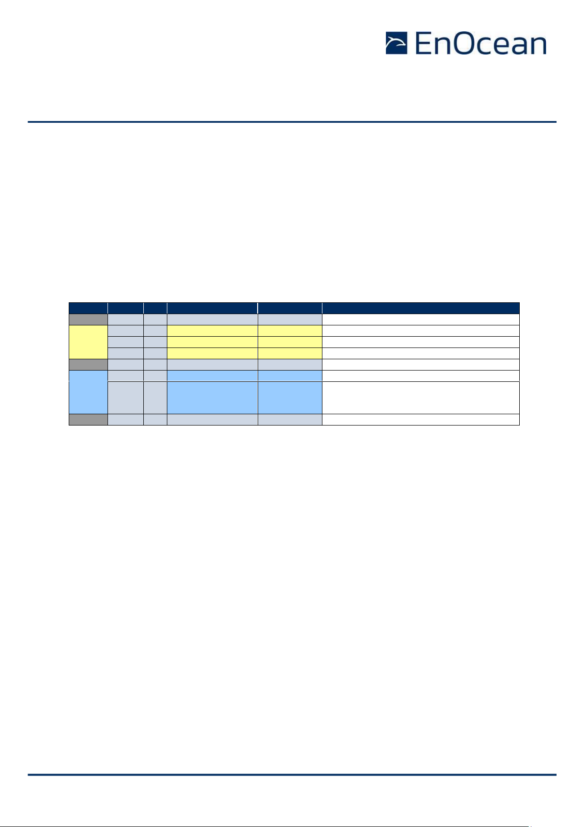
USER MANUAL
TCM 515 – ENOCEAN TRANSCEIVER GATEWAY MODULE
© 2020 EnOcean | www.enocean.com F-710-017, V1.0 TCM 515 User Manual | v1.17 | December 2020 | Page 42/115
5.7 Transmit-only mode
As described in chapter 2.2, TCM 515 is in receive state whenever it is not transmitting a
telegram or has not been put into Sleep state. In some applications such as simple button or
sensor transmitters, TCM 515 is used only for transmission. In these cases, the additional
power consumption in receive state or the added complexity of putting TCM 515 into Sleep
state after each telegram transmission might not be desired.
Starting with TCM 515 product revision DC, reception functionality can be disabled using the
ESP3 command CO_WR_TX_ONLY_MODE so that TCM 515 operates as transmit-only device.
Table 22 below shows the syntax of the CO_WR_TX_ONLY_MODE command.
Group
Offset
Size
Field
Value hex
Description
- 0 1
Sync. byte
0x55
Header
1
2
Data Length
0x0002
2 bytes
3
1
Optional Length
0x00
0 byte
4
1
Packet Type
0x05
0x05: COMMON_COMMAND
- 5 1
CRC8H
0xnn
Data
6
1
COMMAND Code
0x40
0x40: CO_WR_TX_ONLY_MODE
7
1
Enable
0x00
0x01
0x02
0x00: RX / TX Mode (default setting)
0x01: TX-only Mode, Auto Sleep disabled
0x02: TX-only Mode, Auto Sleep enabled
- 8 1
CRC8D
0xnn
Table 22 – Syntax for CO_WR_TX_ONLY_MODE command
If TX-only mode is active and Auto Sleep is disabled, then TCM 515 will transition into Idle
state after completion of a transmission where it will be waiting for reception of the next
ESP3 command requesting the transmission of a telegram. Once such command is received,
TCM 515 will transmit the telegram, report the successful completion of a telegram transmission using the CO_TX_DONE event and then transition back to Idle state waiting for the
next ESP3 command.
If TX-only mode is active and Auto Sleep is enabled, then TCM 515 will transition into indefinite Sleep state after completion of a transmission. In this configuration, TCM 515 will enter
Sleep state in the same way as if it had received a CO_WR_SLEEP command with parameter
0x0000. TCM 515 will remain in Sleep state until it is woken up again via an ESP3 command.
Please refer to chapter 8 for a detailed description of Sleep state.
Page 43

USER MANUAL
TCM 515 – ENOCEAN TRANSCEIVER GATEWAY MODULE
© 2020 EnOcean | www.enocean.com F-710-017, V1.0 TCM 515 User Manual | v1.17 | December 2020 | Page 43/115
6 Telegram repeating
TCM 515 can act as repeater for all or selected radio telegrams. The repeating functionality
is configured via ESP3 interface. Note that repeating functionality is not available if TCM 515
is configured to operate in transmit-only mode as described in chapter 5.7.
If TCM 515 is configured to act as repeater and it receives a radio telegram that it has to
repeat, then TCM 515 will automatically transition from receive to transmit state to re-transmit (repeat) this telegram. After successful transmission, it will automatically transition back
to receive mode.
TCM 515 provides the option to activate a one or two-level repeater for received EnOcean
radio telegrams.
◼ 1-level repeater: If a received telegram is a valid and original (not yet repeated), the
telegram is repeated after a random delay.
◼ 2-level repeater: If a received telegram is valid and original or repeated once, the
telegram is repeated after a random delay.
Repeated telegrams are marked as “repeated” by an increased repeater counter. Configuration of the repeater functionality is done via serial interface commands.
For detailed recommendations regarding the usage of repeaters please refer to our application note EnOcean Wireless Systems - Installation Notes (PDF), 09/2010.
TCM 515 also provides selective repeating, i.e. the option to only repeat certain telegrams
with match pre-defined filter criteria. The filter criteria that can be applied for repeating are
the same as the ones for telegram reception, see chapter 4.2
When using repeaters, care must be taken to ensure that regulatory transmitter
duty cycle limits (if applicable) are not exceeded.
2-level repeating function should only be activated after careful study of the radio conditions! Otherwise the system function can be compromised by collisions
of telegrams.
Page 44

USER MANUAL
TCM 515 – ENOCEAN TRANSCEIVER GATEWAY MODULE
© 2020 EnOcean | www.enocean.com F-710-017, V1.0 TCM 515 User Manual | v1.17 | December 2020 | Page 44/115
6.1 Configuration of telegram repeating
The telegram repeating functionality of TCM 515 is configured using the ESP3 command
CO_WR_REPEATER as shown in Table 23 below.
Group
Offset
Size
Field
Value hex
Description
- 0 1
Sync. byte
0x55
Header
1
2
Data Length
0x0003
3 bytes
3
1
Optional Length
0x00
0 byte
4
1
Packet Type
0x05
0x05: COMMON_COMMAND
- 5 1
CRC8H
0xnn
Data
6
1
COMMAND Code
0x09
0x09: CO_WR_REPEATER
7
1
REP_ENABLE
0x00…0x02
0x00: No repeating
0x01: Repeating of all telegrams
0x02: Selective repeating
8
1
REP_LEVEL
0x00…0x02
0x00: No repeating
0x01: One-level repeating
0x02: Two-level repeating
- 9 1
CRC8D
0xnn
Table 23 – CO_WR_REPEATER
The repeater configuration (no repeating, 1-level repeating, 2-level repeating, selective repeating) is stored persistently in non-volatile memory and will therefore not be affected by a
power cycle.
This mechanism enables the option of configuring USB stick repeaters on a PC via the ESP3
interface and then transferring them to a USB power supply for subsequent operation.
Page 45

USER MANUAL
TCM 515 – ENOCEAN TRANSCEIVER GATEWAY MODULE
© 2020 EnOcean | www.enocean.com F-710-017, V1.0 TCM 515 User Manual | v1.17 | December 2020 | Page 45/115
7 Security processing
TCM 515 implements the security handling functions as specified in the EnOcean security
specification: https://www.enocean-alliance.org/sec/
TCM 515 can receive and decrypt messages from the following EnOcean products:
◼ PTM 215
◼ PTM 535
◼ STM 320 / STM 329 / STM 250 / EMCS (or similar with same profile)
◼ STM 330 / STM 331 (or similar with same profile)
◼ STM 350 / ETHS
◼ STM 550 / EMSI
◼ EMDC
◼ TCM 515
7.1 TCM 515 security architecture
TCM 515 supports all three security mechanisms outlined previously and can manage secure bi-directional connections to up to 32 remote devices using its secure link table.
For each such connection, TCM 515 maintains separate security keys and rolling codes for
the communication to the remote device (outbound, transmission using KEY1 and RLC1)
and for communication from the remote device (inbound, reception using KEY2 and RLC2)
as discussed in chapter B.4.1.
Figure 11 below illustrates the two different directions of secure communication from the
perspective of TCM 515.
Figure 11 – Secure communication flow
Page 46
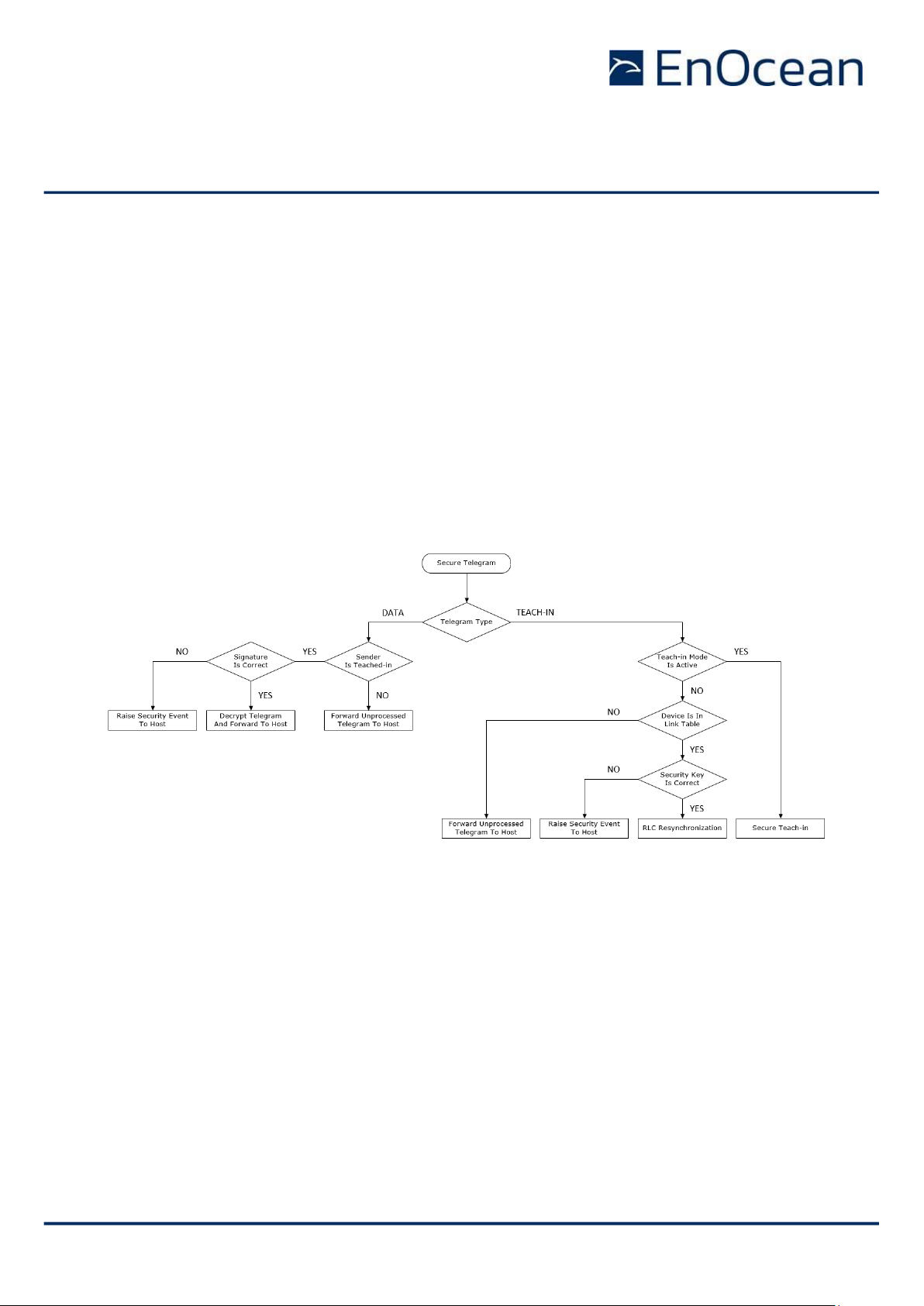
USER MANUAL
TCM 515 – ENOCEAN TRANSCEIVER GATEWAY MODULE
© 2020 EnOcean | www.enocean.com F-710-017, V1.0 TCM 515 User Manual | v1.17 | December 2020 | Page 46/115
7.2 Telegram processing flow
TCM 515 can automatically decrypt and authenticate messages originating from taught-in
remote devices transmitting messages according to the EnOcean Network Security specification.
Security processing requires the receiver to know the security key and the latest rolling code
counter. Therefore, this is only possible for devices that have previously been teached-in as
discussed in chapter 7.7.
If a high security radio telegram is received from a device that has not been teched-in then
TCM 515 will report forward the high security telegram without processing to the host for
further analysis.
Figure 12 below illustrates the high-level processing flow for received EnOcean high security
radio telegrams.
Figure 12 – TCM 515 high security telegram processing flow
Page 47
USER MANUAL
TCM 515 – ENOCEAN TRANSCEIVER GATEWAY MODULE
© 2020 EnOcean | www.enocean.com F-710-017, V1.0 TCM 515 User Manual | v1.17 | December 2020 | Page 47/115
7.3 Secure link table
TCM 515 stores all required information for secure communication with a remote device in
the secure link table. The secure link table can store up to 32 entries in order to manage
secure connection to up to 32 remote devices.
For communication with more than 32 devices it is recommended to execute the security
processing in the external host system.
Note that TCM 515 requires approximately 100 ms to process a secure link
table update request (addition, removal or modification of a link table entry)
which has been received via ESP3. Host SW has to provide a sufficient interval between ESP3 update request and any ESP3 command using the updated
link table entry.
Figure 13 below shows the structure of the secure link table.
Secure Link Table Structure
Index
Remote Device
EURID
Direction
Security
Key
RLC
Teach-In
Info
Security
Format
0
EURID0
Inbound (RX)
KEY0_I
RLC0_I
TI0
SLF0
Outbound (TX)
KEY0_O
RLC0_O
1
EURID1
Inbound (RX)
KEY1_I
RLC1_I
TI1
SLF1
Outbound (TX)
KEY1_O
RLC1_O
2
EURID2
Inbound (RX)
KEY2_I
RLC2_I
TI2
SLF2
Outbound (TX)
KEY2_O
RLC2_O
…
31
EURID31
Inbound (RX)
KEY31_I
RLC31_I
TI31
SLF31
Outbound (TX)
KEY31_O
RLC31_O
Figure 13 – Secure link table structure
Page 48

USER MANUAL
TCM 515 – ENOCEAN TRANSCEIVER GATEWAY MODULE
© 2020 EnOcean | www.enocean.com F-710-017, V1.0 TCM 515 User Manual | v1.17 | December 2020 | Page 48/115
7.3.1 Secure link table parameters
Each entry in the secure link table contains the following parameters:
◼ Index
The index indicates the location of the entry in the secure link table. The table will be
filled starting with Index = 0 and is full once Index = 31
◼ Remote Device EURID
This field contains the EURID (radio address) of the remote device with which TCM
515 can communicate based on the parameters for this entry
◼ Security Key
This field contains the security key used by TCM 515 to transmit telegrams to the
remote device (KEY_O) and the security key used by the remote device to transmit
telegrams to TCM 515 (KEY_I)
◼ RLC
This field contains the RLC used by TCM 515 to transmit telegrams to the remote
device (RLC_O) and the RLC used by the remote device to transmit telegrams to TCM
515 (RLC_I)
◼ Teach-in Info
This field contains information about the type of the remote device (specifically if this
is a rocker switch or not and if A or B side of the rocker switch were used for teachin)
◼ Security Level (SLF)
This field contains the security level (SLF) which specifies the encryption, authentication and RLC parameters used for the communication with the remote device as described below. For bi-directional communication, the same SLF must be used for inbound (telegrams received by TCM 515 from the remote device) and outbound (telegrams transmitted by TCM 515 to the remote device) communication.
Page 49

USER MANUAL
TCM 515 – ENOCEAN TRANSCEIVER GATEWAY MODULE
© 2020 EnOcean | www.enocean.com F-710-017, V1.0 TCM 515 User Manual | v1.17 | December 2020 | Page 49/115
The security processing in TCM 515 supports both secure messages that specify the original
telegram type (RORG) and those who don’t. Table 24 below summarizes the different RORG
supported by TCM 515 security processing.
RORG
Description
0x30
Secure message that does not identify the type (RORG) of the encrypted telegram
0x31
Secure message that does identify the type (RORG) of the encrypted telegram
0x32
Message that results from the decryption of a secure message with RORG = 0x30 (secure message that does not identify the type (RORG) of the encrypted telegram)
0x33
Secure Chained Messages (SEC_CDM, supported starting with product revision DC)
0x35
Secure Teach-in telegram (SEC_TI)
Table 24 – RORG supported by the security implementation in TCM 515
Page 50

USER MANUAL
TCM 515 – ENOCEAN TRANSCEIVER GATEWAY MODULE
© 2020 EnOcean | www.enocean.com F-710-017, V1.0 TCM 515 User Manual | v1.17 | December 2020 | Page 50/115
7.4 Telegram encryption and decryption
TCM 515 used the AES-128 algorithm together with a 16 byte security key and an RLC to
encrypt and decrypt radio telegrams as described in chapter B.2.
TCM 515 supports both VAES and AES-CBC modes of the AES-128 algorithm. The mode which
is used can be selected using the ENCRYPTION_ALGO field in the SLF described in chapter
B.5.1.2.
Refer to the EnOcean Alliance Security Specification for details about the VAES and AES-CBC
modes.
7.5 Telegram authentication
TCM 515 can authenticate the content of received telegrams based on the telegram signature
(CMAC), the security key and a rolling code as described in chapter B.3.
Additionally, TCM 515 can calculate the signature and add it to transmitted telegrams according to the same mechanism.
TCM 515 supports signature lengths of 3 byte and 4 byte. The signature length that is transmitted as part of the telegram is defined by the CMAC_SIZE field in the SLF described in
chapter B.5.1.2.
CMAC_SIZE encodes the following options:
◼ CMAC_SIZE = 0b00: No CMAC is included in the secure telegram
◼ CMAC_SIZE = 0b01: CMAC is a 3 byte long signature
◼ CMAC_SIZE = 0b10: CMAC is a 4 byte long signature
Refer to the EnOcean Alliance Security Specification [4] for details about the CMAC modes.
Page 51

USER MANUAL
TCM 515 – ENOCEAN TRANSCEIVER GATEWAY MODULE
© 2020 EnOcean | www.enocean.com F-710-017, V1.0 TCM 515 User Manual | v1.17 | December 2020 | Page 51/115
7.6 RLC support
TCM 515 supports the use of RLC generated by a monotonously incrementing sequence counter as described in chapter B.4.
TCM 515 supports RLC sizes of 16 bit, 24 bit and 32 bit according to the setting of the
RLC_MODE field in the SLF as described in chapter B.5.1.2.
Note that the 32 bit sequence counter size has been added by EnOcean Alliance in version
2.5 of the EnOcean Alliance Security Specification.
7.6.1 Explicit and implicit rolling code support
TCM 515 supports both explicit RLC mode and implicit RLC mode as described in chapter
B.4.2.
The maximum number of RLC values that will be tested in implicit RLC mode (the RLC Window
size) is 128 in TCM 515. The RLC window size can be temporarily changed (increased) in
order to attempt resynchronization using ESP3 Command Code 33: CO_WR_TEMPORARY_RLC_WINDOW. This increased RLC window is only applied to the first telegram received for each address in the inbound link table after the reception of this command. Refer
to the ESP3 documentation for reference.
If the RLC window has been exhausted without successfully decrypting and authenticating
the telegram, then the telegram will be discarded. In order to re-synchronize the sequence
counter between transmitter and receiver, the transmitter must send a teach-in telegram.
The receiver – upon receiving a valid teach-in telegram from a previously taught-in transmitter – will adjust its own sequence counter to the one specified in the teach-in telegram.
Starting with product revision DC, successful resynchronization of the RLC by means of a
secure teach-in telegram will be indicated to the host by a CO_EVENT_SECUREDEVICES
event with event type 0x0A (successful RLC resynchronization).
Page 52

USER MANUAL
TCM 515 – ENOCEAN TRANSCEIVER GATEWAY MODULE
© 2020 EnOcean | www.enocean.com F-710-017, V1.0 TCM 515 User Manual | v1.17 | December 2020 | Page 52/115
7.6.2 RLC roll-over
For the case of 16 bit or 24 bit RLC sizes, it is possible that the number of transmitted
telegrams during the product lifetime exceeds the amount of possible RLC values. In this
case, the sequence counter that generates the RLC will be reset to zero after reaching the
maximum value (65535 for 16 bit RLC, 16.777.216 for 24 bit RLC) and start counting up
again. This means that previously used RLC values will be used again and is called RLC roll-
over. The case of RLC roll-over can be addressed in two ways:
1. Roll-over is not allowed and the only restriction for consecutive RLC values is that
the most recently received one is higher than previously received ones.
This mode is always used for the 32 bit explicit RLC modes and is the default setting
for the 24 bit explicit RLC mode.
2. Roll-over is allowed but two consecutively received RLC values have to be no more
than a certain value - called RLC Window - apart. The value of RLC Window is 128 in
EnOcean devices.
This mode is used for the 16 bit RLC modes and the 24 bit implicit RLC mode. It is
an option for the 24 bit explicit RLC mode configurable via ESP3 command as described below.
It is possible to select which strategy is applied for the case of 24 bit explicit RLC mode
with the first option (no roll-over allowed) being the default setting. It is possible to select
the second option (roll-over allowed if within RLC window) using the ESP3 command
CO_WR_RLC_LEGACY_MODE as shown in Table 25 below.
Group
Offset
Size
Field
Value hex
Description
- 0 1
Sync. byte
0x55
Header
1
2
Data Length
0x0002
2 bytes
3
1
Optional Length
0x00
0 byte
4
1
Packet Type
0x05
0x05: COMMON_COMMAND
- 5 1
CRC8H
0xnn
Data
6
1
COMMAND Code
0x37
0x37: CO_WR_RLC_LEGACY_MODE
Data
7
1
Legacy Mode
0x00
0x01
0x00: Default setting
No roll-over allowed in 24 bit explicit RLC
mode (SLF = 0b101), no restriction on
distance between consecutive RLC
0x01: Legacy mode
Roll-over allowed in 24 bit explicit RLC
mode (SLF = 0b101), consecutive RLC
must be within RLC WINDOW
- 8 1
CRC8D
0xnn
Table 25 – CO_WR_RLC_LEGACY_MODE
Page 53

USER MANUAL
TCM 515 – ENOCEAN TRANSCEIVER GATEWAY MODULE
© 2020 EnOcean | www.enocean.com F-710-017, V1.0 TCM 515 User Manual | v1.17 | December 2020 | Page 53/115
7.6.3 RLC backup
The constant part of the secure link table entries (device addresses, security keys, security
level format, teach-in info) is stored in non-volatile memory in order to preserve the content in case of a temporary power loss.
In contrast to that, the RLC values – which change for each transmitted or received telegram – are stored in internal volatile memory to optimize encryption and decryption performance since the storage to non-volatile memory requires a significant amount of time.
To account for the option of a power loss, it is necessary to periodically backup the RLC
from volatile to non-volatile memory. The RLC value of a link table entry is by default
backed up to non-volatile memory once for every 64 telegrams that have been sent (outbound RLC – RLC_O) or received (inbound RLC – RLC_I) for that entry.
Should TCM 515 encounter a power loss then the RLC value for each entry in the outbound
link table will be incremented by 64 to account for the possibility that the last backup of the
RLC might have occurred 63 telegrams ago (if power loss occurred directly before the next
RLC backup).
If TCM 515 is continuously power-cycled such that it is only active during a brief period for
the transmission of one or several telegrams, then the transmitted RLC will “jump” by up to
64 every time the device is powered up and transmits a telegram.
It is possible to change the rate at which the RLC is backed up to non-volatile memory from
its default setting of 64 to a user-defined setting using the command
CO_WR_RLC_SAVE_PERIOD as shown in Table 26.
Note that lowering the backup interval will increase the time spent for backing up
the RLC values and thereby reduce the device performance. This function should
therefore only be used if necessary.
Group
Offset
Size
Field
Value hex
Description
- 0 1
Sync. byte
0x55
Header
1
2
Data Length
0x0002
2 bytes
3
1
Optional Length
0x00
0 byte
4
1
Packet Type
0x05
0x05: COMMON_COMMAND
- 5 1
CRC8H
0xnn Data
6
1
COMMAND Code
0x36
0x36: CO_WR_RLC_SAVE_PERIOD
Data
7
1
Save Period
0xnn
0x00: All RLC in the secure link table will
be saved immediately
0x01..0xFF: RLC are saved every n times
- 8 1
CRC8D
0xnn
Table 26 –CO_WR_RLC_SAVE_PERIOD
Using a Save Period of 0 in this command will result in TCM 515 backing up all RLC values
in its link table to non-volatile memory leaving the RLC backup interval otherwise unchanged. This is intended for cases of expected power down where volatile data should be
stored before power loss.
Page 54

USER MANUAL
TCM 515 – ENOCEAN TRANSCEIVER GATEWAY MODULE
© 2020 EnOcean | www.enocean.com F-710-017, V1.0 TCM 515 User Manual | v1.17 | December 2020 | Page 54/115
7.7 Teach-in of secure devices
When establishing secure communication, the sender and the receiver have to agree on the
parameters to be used and exchange the security credentials (security key, current RLC
value). This process is called Secure Teach-in or teach-in in short.
7.7.1 Security parameters
The following security parameters are used to define secure communication between a sender
and a receiver:
◼ Security key
◼ RLC size and current value
◼ Signature (CMAC) size
◼ Security algorithm
Those parameters are described in the subsequent chapters and have to be setup by means
of a secure teach-in procedure as described in chapter 7.7.2.
7.7.1.1 Security key
The security key is a random 128 bit (16 byte) value that is known only to the sender and
the receiver(s). It is used to encrypt, decrypt and authenticate telegrams.
For the case of transmission, TCM 515 defines the security key that will be used to secure
communication. It has to be generated by the external host using a suitable random number
generation algorithm.
For the case of reception, the external sender defines the security key that will be used to
secure communication.
7.7.1.2 RLC
The RLC is a monotonously incrementing counter used to modify the content of secure telegrams as described in chapter B.4. The RLC is generated by the sender and monitored by the
receiver.
The receiver will store the most recently received RLC value and only accept telegrams with
higher RLC values to avoid retransmission of previously transmitted messages.
Page 55

USER MANUAL
TCM 515 – ENOCEAN TRANSCEIVER GATEWAY MODULE
© 2020 EnOcean | www.enocean.com F-710-017, V1.0 TCM 515 User Manual | v1.17 | December 2020 | Page 55/115
7.7.2 Secure teach-in procedure
Secure teach-in can be performed in two different ways:
◼ Using a secure teach-in telegram if TCM 515 is in teach-in mode (see chapter 7.7.3)
TCM 515 can automatically derive the required parameters for telegram encryption,
decryption and authentication from such secure teach-in telegram.
Conversely, TCM 515 can also be instructed via its ESP3 interface to transmit such
secure teach-in telegram to a remote device.
◼ Using an ESP3 command (see chapter 0)
The required parameters for telegram encryption, decryption and authentication can
also be configured TCM 515 can be configured via an ESP3 command
In both cases, the configured parameters have to be the same for both the sender and the
receiver.
Until secure communication has been established, TCM 515 will forward received telegrams
to the external host and transmit telegrams from the external host without security processing. If secure communication between a remote device and TCM 515 has been established, then TCM 515 will handle all security-related functionality such as encryption, decryption, authentication and RLC management. This greatly facilitates the implementation of secure communication in resource-constrained applications such as simple actuators.
7.7.3 Teach-in of secure devices with secure teach-in telegram
Teach-in is the process by which a remote device communicates to TCM 515 all parameters
required to establish secure communication using a special radio telegram as described in
Appendix B.5.1.
7.7.3.1 Transmission of a secure teach-in telegram
If the parameters for secure communication with a remote device have been setup in the
outbound link table, then a secure teach-in telegram can be transmitted to that device using the CO_WR_SENDTEACHIN command as shown in Table 27 below.
Group
Offset
Size
Field
Value hex
Description
- 0 1
Sync. byte
0x55
Header
1
2
Data Length
0x0005
5 bytes
3
1
Optional Length
0x00...0x01
1 byte
4
1
Packet Type
0x05
0x05: COMMON_COMMAND
- 5 1
CRC8H
0xnn
Data
6
1
COMMAND Code
0x20
0x20: CO_WR_SECUREDEVICE_SENDTEACHIN
8
4
ID
0xnnnnnnnn
Device ID
Optional
Data
8
1
TeachInInfo
0xnn
Teach-In Info
- -
1
CRC8D
0xnn
Table 27 – CO_WR_SECUREDEVICE_SENDTEACHIN
Page 56

USER MANUAL
TCM 515 – ENOCEAN TRANSCEIVER GATEWAY MODULE
© 2020 EnOcean | www.enocean.com F-710-017, V1.0 TCM 515 User Manual | v1.17 | December 2020 | Page 56/115
7.7.3.2 Reception of a secure teach-in telegram (Teach-in mode)
TCM 515 can be configured to automatically accept secure teach-in telegrams and store
their parameters in the secure link table by enabling the so-called Teach-in Mode. Teach-in
mode can be enabled for a specific time (the default setting is 60 seconds) using the
CO_WR_LEARNMODE command shown in Table 28 below.
Group
Offset
Size
Field
Value hex
Description
- 0 1
Sync. byte
0x55
Header
1
2
Data Length
0x0006
6 bytes
3
1
Optional Length
0x01
1 byte
4
1
Packet Type
0x05
0x05: COMMON_COMMAND
- 5 1
CRC8H
0xnn
Data
6
1
COMMAND Code
0x17
0x17: CO_WR_LEARNMODE
7
1
Enable
0x0n
0x00: Stop Teach-in Mode
0x01: Start Teach-in mode
8
4
Timeout
0xnnnnnnnn
Time-Out for Teach-in Mode in ms.
When time is set to 0x00000000 then the
default period of 60’000 ms is used
Optional
Data
12
1
Channel
0xnn
0x00 ... 0xFD: Channel number (absolute)
0xFE Previous channel (relative)
0xFF Next channel (relative)
- - 1
CRC8D
0xnn
Table 28 – CO_WR_LEARNMODE
If a valid teach-in telegram is received while teach-in mode is active, then an entry with the
corresponding parameters is added to the inbound secure link table.
Starting with product version DC, TCM 515 will indicate successful teach-in with a
CO_EVENT_SECUREDEVICES event message as described in chapter 7.8. Also starting with
product version DC-10, TCM 515 will indicate that the teach-in mode has ended by sending
the Event CO_LRN_MODE_DISABLED shown in Table 29 below.
Group
Offset
Size
Field
Value hex
Description
- 0 1
Sync. byte
0x55
Header
1
2
Data Length
0x0001
1 bytes
3
1
Optional Length
0x00
0 byte
4
1
Packet Type
0x04
0x04: EVENT
- 5 1
CRC8H
0xnn
Data
6
1
Event Code
0x09
0x09: CO_LRN_MODE_DISABLED
- 7 1
CRC8D
0xnn
Table 29 – CO_LRN_MODE_DISABLED
The maximum number of remote devices that can be teached-in is 32. Attempting to teach
in additional devices will result in a CO_EVENT_SECUREDEVICES with error code 00 (Teach
in failed, because no more space available).
If TCM 515 is not in teach-in mode and it receives a valid (same key, same SLF, same
Teach-in Info) secure teach-in telegram then it will adjust its inbound RLC to the RLC specified within this secure teach-in telegram as described in chapter 7.7.3.3.
Page 57

USER MANUAL
TCM 515 – ENOCEAN TRANSCEIVER GATEWAY MODULE
© 2020 EnOcean | www.enocean.com F-710-017, V1.0 TCM 515 User Manual | v1.17 | December 2020 | Page 57/115
7.7.3.3 Handling of secure teach-in telegrams if teach-in mode is not
active
If TCM 515 is not in teach-in mode, then secure teach-in telegrams from unknown senders
are ignored.
If TCM 515 receives a secure teach-in telegram from a known (previously teched-in) sender
containing the correct security key, then the sequence counter information in the TCM 515
secure link table is updated to the value specified in the telegram. This approach is used in
case sequence counters of receiver and sender become desynchronized.
Starting with product version DC, TCM 515 will indicate a successful sequence counter resynchronization using this mechanism by sending a CO_EVENT_SECUREDEVICES event message as described in chapter 7.8.
Page 58

USER MANUAL
TCM 515 – ENOCEAN TRANSCEIVER GATEWAY MODULE
© 2020 EnOcean | www.enocean.com F-710-017, V1.0 TCM 515 User Manual | v1.17 | December 2020 | Page 58/115
7.7.4 Teach-in of secure devices using ESP3
The security parameters required for secure communication with a remote device can also
be setup by the external host via the ESP3 interface using the CO_WR_SECUREDEVICE_ADD
command.
This approach is always used for the case of outbound communication (from TCM 515 to the
remote device). This approach might also be used (instead of relying on secure teach-in
telegrams) for inbound communication (from the remote device to TCM 515) if the relevant
parameters are known to the local host. This could for instance be the case if the security
information of the remote device has been read by the host from a QR code on the remote
device.
The information provided will either be added to the inbound (reception) or to the outbound
(transmission) link table depending on the value of the Direction field. For the case of addition
to the outbound link table, setting the ID field to the own EURID (or 0x00000000) will cause
the provided information to be used for secure broadcast transmissions. Otherwise it will be
used for secure addressed transmissions to the specified ID.
Group
Offset
Size
Field
Value hex
Description
- 0 1
Sync. byte
0x55
Header
1
2
Data Length
0x0019
25 bytes
3
1
Optional Length
0x02
2 bytes
4
1
Packet Type
0x05
0x05: COMMON_COMMAND
- 5 1
CRC8H
0xnn
Data
6
1
COMMAND Code
0x19
0x19: CO_WR_SECUREDEVICE_ADD
7
1
SLF
0xnn
Security Level Format
8
4
ID
0xnnnnnnnn
Device ID
12
16
Private key
0xnnnnnnnn
0xnnnnnnnn
0xnnnnnnnn
0xnnnnnnnn
16 bytes private key of the device
28
3
Rolling code
0xnnnnnn
If a 16 bit rolling code is defined in SLF, the
MSB is undefined
Optional
Data
31
1
Direction
0xnn
Add device security information to:
0x00: Inbound table (default)
ID = Source EURID
0x01: Outbound table
ID = Destination EURID
Used for secure addressed telegrams
ID = Own EURID or 0x00000000
Used for secure broadcast telegrams
0x02 ... 0xFF: Not used
32
1
PTM Sender
0xnn
0x00: Not a PTM sender
0x01: PTM sender
0x02 … 0xFF: Not Used
33
1
Teach-Info
0x0n
Secure device Teach-In info
- - 1
CRC8D
0xnn
Table 30 – CO_WR_SECUREDEVICE_ADD
Note that the CO_WR_SECUREDEVICE_ADD allows only adding devices using 2 byte or 3
byte rolling code size.
Page 59

USER MANUAL
TCM 515 – ENOCEAN TRANSCEIVER GATEWAY MODULE
© 2020 EnOcean | www.enocean.com F-710-017, V1.0 TCM 515 User Manual | v1.17 | December 2020 | Page 59/115
Due to the recent addition of the option for using 4 byte rolling code size into the EnOcean
Alliance Security Specification, the new command CO_WR_SECUREDEVICEV2_ADD has been
defined.
This command is supported starting with product revision DB-09 and uses the structure
shown in
Table 31 below.
Exactly as for the CO_WR_SECUREDEVICE_ADD command, the information provided will either be added to the inbound (reception) or to the outbound (transmission) link table depending on the value of the Direction field.
For the case of addition to the outbound link table, setting the ID field to the own EURID (or
0x00000000) will cause the provided information to be used for secure broadcast transmissions. Otherwise it will be used for secure addressed transmissions to the specified ID.
Group
Offset
Size
Field
Value hex
Description
- 0 1
Sync. byte
0x55
Header
1
2
Data Length
0x0018
27 bytes
3
1
Optional Length
0x01
1 bytes
4
1
Packet Type
0x05
0x05: COMMON_COMMAND
- 5 1
CRC8H
0xnn
Data
6
1
COMMAND Code
0x38
0x38: CO_WR_SECUREDEVICE2_ADD
7
1
SLF
0xnn
Security Level Format
8
4
ID
0xnnnnnnnn
Device ID
12
16
Private key
0xnnnnnnnn
0xnnnnnnnn
0xnnnnnnnn
0xnnnnnnnn
16 bytes private key of the device
28
4
Rolling code
0xnnnnnnnn
If a 24/16 bit rolling code is defined in SLF,
then the MSBs are undefined
32
1
Teach-Info
0xnn
Full SEC_TEACH_INFO, like defined in the security SPEC
Optional
Data
31
1
Direction
0xnn
Add device security information to:
0x00: Inbound table (default)
ID = Source EURID
0x01: Outbound table
ID = Destination EURID
Used for secure addressed telegrams
ID = Own EURID or 0x00000000
Used for secure broadcast telegrams
0x02 ... 0xFF: Not used
-
48
1
CRC8D
0xnn
Table 31 – CO_WR_SECUREDEVICE2_ADD
Page 60

USER MANUAL
TCM 515 – ENOCEAN TRANSCEIVER GATEWAY MODULE
© 2020 EnOcean | www.enocean.com F-710-017, V1.0 TCM 515 User Manual | v1.17 | December 2020 | Page 60/115
7.8 Reporting of security-related events
TCM 515 can report to the host the following security-related events by means of a
CO_EVENT_SECUREDEVICES event using the structure shown below.
Group
Offset
Size
Field
Value hex
Description
- 0 1
Sync. byte
0x55
Header
1
2
Data Length
0x0006
6 bytes
3
1
Optional Length
0x00
0 byte
4
1
Packet Type
0x04
0x04: EVENT
- 5 1
CRC8H
0xnn
Data
6
1
Event Code
0x05
0x05: CO_EVENT_SECUREDEVICES
7
1
Event Type
0xnn
0x00: Teach in failed because no more space
is available in the secure link table
0x02: Resynchronization attempt with wrong
private key
0x03: Configured count of telegrams with
wrong CMAC received
0x04: Teach-in failed due to incorrect teachin telegram content or format
0x07: CMAC or RLC not correct
0x08: Standard telegram received from de-
vice in secure link table
0x09: Teach-In successful
0x0A: Received valid RLC sync via Teach-In
Others: Reserved or not supported
8 4
Device ID
0xnnnnnnnn
Device ID
-
12
1
CRC8D
0xnn
Table 32 – Secure event reporting
The following reporting codes are supported by TCM 515:
◼ 0x00: Teach in failed, no more space is available in the secure link table
◼ 0x02: Resynchronization attempt with wrong private key
Secure teach in telegram received with non-matching security key from device already
in the link table
◼ 0x03: Configured count of telegrams with wrong CMAC received
128 messages with wrong CMAC have been received from the same sender
◼ 0x04: Teach-In failed due to unexpected structure and content
◼ 0x07: CMAC or RLC not correct, the received CMAC did not match the expected CMAC
after exhausting all RLC within the RLC window
◼ 0x08: Standard telegram received from device in secure link table
◼ 0x09: Teach-in successful (from version DC-10)
◼ 0x0A: Successful RLC resync via secure teach-in telegram (from version DC-10)
Page 61

USER MANUAL
TCM 515 – ENOCEAN TRANSCEIVER GATEWAY MODULE
© 2020 EnOcean | www.enocean.com F-710-017, V1.0 TCM 515 User Manual | v1.17 | December 2020 | Page 61/115
8 Low power sleep mode
TCM 515 can be set into a low power sleep mode for a defined period of time by means of
the CO_WR_SLEEP command shown in Table 33 below. After expiry of the requested sleep
period, TCM 515 will automatically wake-up and transition back to receive mode.
Group
Offset
Size
Field
Value hex
Description
- 0 1
Sync. byte
0x55
Header
1
2
Data Length
0x0005
5 bytes
3
1
Optional Length
0x00
0 byte
4
1
Packet Type
0x05
0x05: COMMON_COMMAND
- 5 1
CRC8H
0xnn
Data
6
1
COMMAND Code
0x01
0x01: CO_WR_SLEEP
7
4
Deep sleep period
0x00nnnnnn
0x00000000: Wake by UART
Supported from revision DB-09
0x00000001 … 0x00FFFFFF:
Duration of sleep in 10 ms units (maximum value ~ 46h). After waking up, the
module generates an internal hardware
reset
-
11
1
CRC8D
0xnn
Table 33 – CO_WR_SLEEP
Starting with device revision DB-09, it is possible to put TCM 515 into low power sleep
mode indefinitely by using 0x00000000 as sleep period. TCM 515 will in this case remain in
low power sleep mode until it is woken up by the external host via activity on the ESP3 interface.
Any activity on the ESP3 interface will wake-up TCM 515 in this case but the command
used for wake-up will not be processed. Any ESP3 command can be used for the purpose of
wake-up; it is suggested however to use a command without possible side effects such as
CO_RD_VERSION.
Page 62

USER MANUAL
TCM 515 – ENOCEAN TRANSCEIVER GATEWAY MODULE
© 2020 EnOcean | www.enocean.com F-710-017, V1.0 TCM 515 User Manual | v1.17 | December 2020 | Page 62/115
9 ESP3 interface
TCM 515 provides an external interface according to the EnOcean Serial Protocol, version 3
(ESP3).
This interface is used both to exchange telegrams and command / status messages with an
external host system (e.g. microcontroller or PC) and EnOcean gateway transceiver modules.
The information in the subsequent chapters as well as any previous references to specific
ESP3 commands are provided for information purposes only. For detailed information, please
refer to the ESP3 specification [1].
9.1 ESP3 physical interface
The physical interface used by ESP3 for communication between host system and an EnOcean
Gateway Controller is a 3-wire full duplex UART / RS-232 connection (RX, TX, GND).
The standard UART baud rate is 57600 baud per second. TCM 515 supports a higher baud
rate of 460800 baud per second which can be selected using the command CO_SET_BAUDRATE as shown in Table 34 below.
Group
Offset
Size
Field
Value hex
Description
- 0 1
Sync. byte
0x55
Header
1
2
Data Length
0x0002
2 bytes
3
1
Optional Length
0x00
0 byte
4
1
Packet Type
0x05
0x05: COMMON_COMMAND
- 5 1
CRC8H
0xnn
Data
6
1
COMMAND Code
0x24
0x24: CO_SET_BAUDRATE
7
1
BAUDRATE
0xnn
0x00: 57600 baud
0x01: Not supported
0x02: Not supported
0x03: 460800 baud
- - 1
CRC8D
0xnn
Table 34 – CO_SET_BAUDRATE
Before changing the baud rate please make sure that the connected host supports the selected setting; otherwise communication will be lost and the device has to be reset to restore the previous baud rate.
Page 63

USER MANUAL
TCM 515 – ENOCEAN TRANSCEIVER GATEWAY MODULE
© 2020 EnOcean | www.enocean.com F-710-017, V1.0 TCM 515 User Manual | v1.17 | December 2020 | Page 63/115
9.2 ESP3 packet structure
ESP3 is a point-to-point (one to one) protocol based on a packet data structure.
Figure 14 below illustrates the ESP3 packet structure.
Figure 14 – ESP3 Packet Structure
Each ESP3 packet contains the following fields:
◼ Header
◼ Data
◼ Optional Data.
In addition to those fields, the Sync byte (0x55) identifies the start of the packet while separate CRC8 for Header and Data (incl. Optional Data) are used to verify data integrity.
The Header consists of the following fields:
◼ Data Length (number of bytes of the group Data)
◼ Optional Length (number of bytes of the group Optional Data)
◼ Packet Type (RADIO, RESPONSE, EVENT, COMMAND ...)
The Data field encodes the ESP3 command together with the required parameter data. For
some commands, the Optional Data field is used to provide additional parameter data.
The maximum length of an ESP3 packet in TCM 515 is 255 byte.
Header
Data
Optional Data
Sync byte
CRC8 Header
CRC8 Data
Data Length
Packet Type
Optional Length
ESP3 Packet Structure
ESP3
Packet
Page 64

USER MANUAL
TCM 515 – ENOCEAN TRANSCEIVER GATEWAY MODULE
© 2020 EnOcean | www.enocean.com F-710-017, V1.0 TCM 515 User Manual | v1.17 | December 2020 | Page 64/115
9.3 Supported ESP3 commands
The following ESP3 commands are supported by TCM 515:
◼ Type 1: ERP1 Radio Telegram
◼ Type 2: Responses
o RET_OK
o RET_ERROR
o RET_NOT_SUPPORTED
o RET_WRONG_PARAM
o RET_OPERATION_DENIED
o RET_LOCK_SET
o RET_BUFFER_TO_SMALL
o RET_NO_FREE_BUFFER
◼ Type 4: Events
o SA_CONFIRM_LEARN to confirm/discard SmartAck learn in/out
o CO_READY to indicate wake up from deep sleep initiated by CO_WR_SLEEP
o CO_EVENT_SECUREDEVICES to inform about security processing issues
o CO_DUTYCYCLE_LIMIT to inform about a current limitation due to duty cycle
o CO_TX_DONE to inform that the transmission of a telegram has completed
o CO_LRN_MODE_DISABLED to inform that the learn mode has timed-out
◼ Type 5: Common commands
o CO_WR_RESET to reset the device
o CO_RD_VERSION to read SW/HW versions, chip ID etc.
o CO_GET_FREQUENCY_INFO to read the operating frequency of the device
o CO_WR_STARTUP_DELAY
o CO_WR_SLEEP to put the device into low power sleep mode
o CO_WR_IDBASE to set the Base ID range
o CO_RD_IDBASE to read the Base ID range
o CO_WR_REPEATER to set repeater functionality
o CO_RD_REPEATER to read repeater functionality
o CO_WR_FILTER_ADD to add filter to filter list or to selective repeating
o CO_WR_FILTER_DEL and CO_WR_FILTER_DEL_ALL to delete filters
o CO_RD_FILTER to read the configured filters
o CO_WR_FILTER_ENABLE to enable/disable the configured filters
o CO_WR_LEARNMODE to set teach-in mode
o CO_RD_LEARNMODE to read teach-in mode status
o CO_WR_WAIT_MATURITY to wait until the end of the maturity time
o CO_RD_DUTYCYCLE_LIMIT to read the duty cycle (for 868 MHz EU version)
o CO_SET_NOISETHRESHOLD to set the input noise rejection threshold
o CO_GET_NOISETHRESHOLD to read the input noise rejection threshold
o CO_WR_REMAN_REPEATING to set the repeater level of Reman messages
o CO_RD_REMAN_REPEATING to read the repeater level Reman messages
o CO_SET_BAUDRATE to set the baud rate of the ESP3 interface
o CO_WR_SECUREDEVICE_ADD to add a device to a link table
o CO_WR_SECUREDEVICE_DEL to delete a device from a link table
o CO_RD_SECUREDEVICE_COUNT to read the number of devices in a link table
o CO_RD_SECUREDEVICE_BY_INDEX to read a link table entry using its index
Page 65

USER MANUAL
TCM 515 – ENOCEAN TRANSCEIVER GATEWAY MODULE
© 2020 EnOcean | www.enocean.com F-710-017, V1.0 TCM 515 User Manual | v1.17 | December 2020 | Page 65/115
o CO_RD_SECUREDEVICE_BY_ID to read a link table entry using its EURID
o CO_WR_SECUREDEVICE_SENDTEACHIN to send a secure teach-in telegram
o CO_WR_RLC_SAVE_PERIOD to set the interval for the backup of RLC values
o CO_WR_RLC_LEGACY_MODE to set the legacy RLC mode (window-based)
o CO_WR_SECUREDEVICEV2_ADD to add a device to a link table
o CO_RD_SECUREDEVICEV2_BY_INDEX to read a link table entry using its index
o CO_WR_RSSITEST_MODE to enable RSSI test mode
o CO_RD_RSSITEST_MODE to read the status of RSSI test mode
o CO_WR_SECUREDEVICE_MAINTENANCEKEY to set the Reman security key
o CO_RD_SECUREDEVICE_MAINTENANCEKEY to read the Reman security key
o CO_WR_TRANSPARENT_MODE to enable transparent mode
o CO_RD_TRANSPARENT_MODE to check if transparent mode is active
o CO_WR_TX_ONLY_MODE to enable TX-only mode
o CO_RD_TX_ONLY_MODE to check if TX-only mode is active
◼ Type 6 Smart Acknowledge commands (postmaster / mailbox functions)
TCM 515 contains 19 Smart Acknowledge mailboxes which can be configured using
the following commands:
o SA_WR_LEARNMODE to set/reset Smart Acknowledge learn mode
o SA_RD_LEARNMODE to get learn mode
o SA_WR_LEARNCONFIRM to add or delete a mailbox of a client
o SA_WR_RESET to send a reset command to a client
o SA_RD_LEARNEDCLIENTS to get learned mailboxes/clients
o SA_WR_POSTMASTER to activate/deactivate post master functionality
◼ Type 7 Remote Management
o Messages with up to 255 byte of payload
◼ Type 9 Radio Message (ERP1 or ERP2)
o Messages with up to 255 byte of payload. TCM 515 will automatically chain
(segment) / de-chain (reassemble) messages as needed based on the maximum payload size of EnOcean radio telegrams
◼ Type 10: ERP2 Radio Telegram (TCM 515U only, use for reception selected using
CO_WR_MODE command)
Page 66

USER MANUAL
TCM 515 – ENOCEAN TRANSCEIVER GATEWAY MODULE
© 2020 EnOcean | www.enocean.com F-710-017, V1.0 TCM 515 User Manual | v1.17 | December 2020 | Page 66/115
9.4 Persistent versus not persistent configuration settings
TCM 515 will store certain configuration settings in persistent memory, i.e. those settings will
be maintained even after a power cycle.
There are three classes of persistent settings:
1. Repeater and filter configuration
Starting from product version DA-08 (see chapter 15), the repeater and filter configuration defined via the following commands will be maintained after power failure:
o CO_WR_REPEATER
o CO_WR_FILTER_ADD
o CO_WR_FILTER_DEL
o CO_WR_FILTER_DEL_ALL
o CO_WR_FILTER_ENABLE
2. List of secure devices as defined by the following commands:
o CO_WR_SECUREDEVICE_ADD or CO_WR_SECUREDEVICEV2_ADD
o CO_WR_SECUREDEVICE_DEL
3. System parameters as defined by the following commands:
o CO_WR_STARTUP_DELAY
o CO_SET_NOISETHRESHOLD
o CO_WR_IDBASE
o CO_WR_RLC_SAVE_PERIOD
o CO_WR_TX_ONLY_MODE
All other settings need to be reinitialized at power up.
Page 67

USER MANUAL
TCM 515 – ENOCEAN TRANSCEIVER GATEWAY MODULE
© 2020 EnOcean | www.enocean.com F-710-017, V1.0 TCM 515 User Manual | v1.17 | December 2020 | Page 67/115
10 Remote management
TCM 515 provides a transparent radio channel also for remote management messages with
a message length of up to 255 bytes. This enables an external micro controller connected to
TCM 515 to handle remote management request from external devices or to control other
devices via remote management.
For more information on remote management please refer to the EnOcean End Equipment
Profiles (EEP) specification [5] and the Remote Management specification [7].
Page 68

USER MANUAL
TCM 515 – ENOCEAN TRANSCEIVER GATEWAY MODULE
© 2020 EnOcean | www.enocean.com F-710-017, V1.0 TCM 515 User Manual | v1.17 | December 2020 | Page 68/115
11 Device integration
TCM 515 is designed for integration onto a host PCB. Detailed Gerber data of the device
footprint is available from EnOcean.
11.1 Recommended PCB Footprint
Figure 15 below shows the recommended PCB footprint for TCM 515.
Figure 15 – Recommended PCB footprint
Page 69

USER MANUAL
TCM 515 – ENOCEAN TRANSCEIVER GATEWAY MODULE
© 2020 EnOcean | www.enocean.com F-710-017, V1.0 TCM 515 User Manual | v1.17 | December 2020 | Page 69/115
11.2 Device outline
Figure 16 below shows the device outline of TCM 515. In addition, EnOcean can provide upon
request a 3D model of TCM 515.
Figure 16 – Device outline
Page 70

USER MANUAL
TCM 515 – ENOCEAN TRANSCEIVER GATEWAY MODULE
© 2020 EnOcean | www.enocean.com F-710-017, V1.0 TCM 515 User Manual | v1.17 | December 2020 | Page 70/115
11.3 Soldering information
TCM 515 shall be soldered according to IPC/JEDEC J-STD-020C standard.
Figure 17 – Recommended soldering profile
TCM 515 shall be handled according to Moisture Sensitivity Level MSL4 which means a floor
time of 72 h. TCM 515 may be soldered only once, since one time is already consumed at
production of the module itself.
Once the dry pack bag is opened, the desired quantity of units should be removed and the
bag resealed within two hours. If the bag is left open longer than 30 minutes the desiccant
should be replaced with dry desiccant. If devices have exceeded the specified floor life time
of 72 h, they may be baked according IPC/JEDEC J-STD-033B at max. 90°C for less than 60
h.
Devices packaged in moisture-proof packaging should be stored in ambient conditions not
exceeding temperatures of 40 °C or humidity levels of 90% r.H.
TCM 515 modules shall be soldered within 6 months after delivery!
Page 71

USER MANUAL
TCM 515 – ENOCEAN TRANSCEIVER GATEWAY MODULE
© 2020 EnOcean | www.enocean.com F-710-017, V1.0 TCM 515 User Manual | v1.17 | December 2020 | Page 71/115
11.4 Packaging information
TCM 515 is delivered in Tape & Reel packaging with 250 units per reel. Figure 18 below
illustrates the dimensions.
Figure 18 – Tape & Reel dimensions of TCM 515
Figure 19 below shows the positioning of TCM 515 in the Tape & Reel packaging.
Figure 19 – Position of TCM 515 in the reel
Page 72

USER MANUAL
TCM 515 – ENOCEAN TRANSCEIVER GATEWAY MODULE
© 2020 EnOcean | www.enocean.com F-710-017, V1.0 TCM 515 User Manual | v1.17 | December 2020 | Page 72/115
11.5 Layout recommendations
The length of lines connected to I/O signals should not exceed 5 cm.
It is recommended to have a complete GND layer in the application PCB, at least in
the area below the module and directly connected components (e.g. mid-layer of your
application PCB).
Due to non-isolated test points there are live signals accessible on the bottom side of
the module. We suggest avoiding any copper structure in the area directly underneath
the module (top-layer layout of your application PCB). If this is not possible in your
design, please provide coating on top of your PCB to prevent short circuits to the
module. All bare metal surfaces including vias have to be covered (e.g. adequate
layout of solder resist).
Distortive signals (e.g. bus signals or power lines) should not be routed underneath
the module. If such signals are present in your design, we suggest separating them
by using a ground plane between module and these signal lines.
For applications with strong external noise sources (e.g. gateways with LTE functionality) it is strongly recommended to use an external SAW filter. See chapter 11.8.
If distortion / radiated noise cannot be minimized to acceptable levels then consider
also using the adjustable internal noise filter. See chapter 11.8.
Page 73

USER MANUAL
TCM 515 – ENOCEAN TRANSCEIVER GATEWAY MODULE
© 2020 EnOcean | www.enocean.com F-710-017, V1.0 TCM 515 User Manual | v1.17 | December 2020 | Page 73/115
11.6 Power supply requirements
In order to provide a good radio performance, great attention must be paid to the power
supply and a correct layout and shielding. It is recommended to place a 22 µF ceramic capacitor between VDD and GND close to the module (material: X5R, X7R, min 6.3 V to avoid
derating effects).
In addition, an HF SMD EMI Suppression Ferrite Bead such as the Würth WE-CBF HF SMD
EMI Suppression Ferrite Bead (Würth order number 742863160) shall be inserted in the
power supply line.
For best performance it is recommended to keep the ripple on the power supply rail below
10 mVpp.
Radiated emissions from power supply inductors (especially DCDC inductors) towards the
TCM 515 RF input must be minimized as they impact RF performance. Place such inductors
as much as possible away from TCM 515 or – if this is not possible – consider using switched
capacitor designs.
TCM 515 integrates approximately 10 uF of capacitance for filtering the internal supply voltage bus. The power supply architecture has to be capable of supplying sufficient current to
charge this capacitance during power up.
11.7 Using an SAW Filter with TCM 515 (868 MHz version only)
Applications using the 868 MHz (EU) frequency band can be affected by strong external noise
sources such as LTE modems or RFID scanners operating in the 860 MHz band.
For best performance, TCM 515 has to be separated as far as possible from such noise
sources. Additionally, the use of an external SAW filter is strongly recommended if such noise
sources might be present. The recommended SAW filter is B3744 from RF360JV (Qualcomm
/ TDK joint venture).
At the time of writing, documentation about B3744 was available under the following link:
https://en.rf360jv.com/inf/40/ds/ae/B3744.pdf
The recommended application circuit for B3744 is shown in Figure 20 below.
Figure 20 – SAW application circuit for 868 MHz
Page 74

USER MANUAL
TCM 515 – ENOCEAN TRANSCEIVER GATEWAY MODULE
© 2020 EnOcean | www.enocean.com F-710-017, V1.0 TCM 515 User Manual | v1.17 | December 2020 | Page 74/115
11.8 Low noise design considerations
For best performance, HW design of TCM 515 systems has to minimize radiated or conducted
noise that interferes with the correct reception of RF signals. Strong emphasis should therefore be placed onto good RF and power supply design to eliminate or minimize the level of
noise introduced into the RF path.
In addition, special consideration should be used to minimize periodic noise sources (such as
radiated noise from DCDC inductors) in TCM 515 based systems. Those systems transmit
and receive signals using amplitude shift keying (868.3 MHz ASK) where the amplitude of a
carrier frequency (868.3 MHz) is changed according to the encoded bit value (0 = high amplitude or 1 = low amplitude).
Periodic noise signals where the time period between high and low signal states is close to
the symbol duration of 8us can be erroneously interpreted as the preamble of an ASK telegram (10101010 sequence) and therefore prevent correct reception of other ASK telegrams
that are received at the same time.
Using HW filtering (separate signal lines and sufficient ground plane in the layout, decoupling
and filtering on the power supply, implementation of SAW filter in the antenna path) should
always be the first priority to minimize the performance degradation due to noise.
In some applications it might not be possible to sufficiently minimize external noise due to
space or design constraints. For those cases, TCM 515 provides an adjustable noise filter.
This noise filter can be configured via ESP3 using the CO_SET_NOISETHRESHOLD command
to reject input noise below the configured minimum signal strength. The structure of the
ESP3 command CO_SET_NOISETHRESHOLD is shown below.
- 0 1
Sync. byte
0x55
Header
1
2
Data Length
0x0002
2 bytes
3
1
Optional Length
0x00
0 byte
4
1
Packet Type
0x05
0x05: COMMON_COMMAND
- 5 1
CRC8H
0xnn
Data
6
1
COMMAND Code
0x32
0x32: CO_SET_NOISETHRESHOLD
7
4
RSSI level
0xnn
RSSI Level to initiate telegram detection
-
11
1
CRC8D
0xnn
Table 35 – CO_SET_NOISETHRESHOLD command structure
Page 75

USER MANUAL
TCM 515 – ENOCEAN TRANSCEIVER GATEWAY MODULE
© 2020 EnOcean | www.enocean.com F-710-017, V1.0 TCM 515 User Manual | v1.17 | December 2020 | Page 75/115
The noise threshold is encoded as positive offset from the theoretical noise minimum (-146
dBm) as shown in the table below. The default value is 0x32 (-96 dBm). Note that for the
case of ASK modulation (868.3 MHz), the minimal signal strength of a detectable telegram
has to be at least 3 dBm above the configured noise threshold.
Value
Noise Threshold
0x2E
-100 dBm
0x2F
-99 dBm
0x30
-98 dBm (Default value TCM 515U)
0x31
-97 dBm
0x32
-96 dBm (Default value TCM 515)
0x33
-95 dBm
0x34
-94 dBm
0x35
-93 dBm
0x36
-92 dBm
0x37
-91 dBm
0x38
-90 dBm
Table 36 – Noise threshold encoding for CO_SET_NOISETHRESHOLD
For environments with strong noise which cannot be sufficiently reduced, consider using an
external SAW filter as described in chapter 11.7 to minimize out of band noise. Alternatively,
consider using a TCM 310 device which integrates an SAW filter.
11.9 Suggested Reset circuit
TCM 515 can be reset by pulling the nRESET pin (active low) to Ground. TCM 515 integrated
a weak (50kΩ) pull-up resistor that will maintain the internal nRESET input active high (not
active).
In order to avoid spurious reset events, it is recommended to filter the input signals by means
of a small capacitor which is placed as close as possible to the TCM 515 nRESET pin as shown
in Figure 21 below.
Figure 21 – Recommended reset circuit
The reset pulse should have a duration of at least 1 ms in order to guarantee reliable reset
operation.
Page 76

USER MANUAL
TCM 515 – ENOCEAN TRANSCEIVER GATEWAY MODULE
© 2020 EnOcean | www.enocean.com F-710-017, V1.0 TCM 515 User Manual | v1.17 | December 2020 | Page 76/115
11.10 Test interface
TCM 515 provides 3 test points (TP1, TP2, TP3) which together with the RESET, UART_TX
and UART_RX signals can be used for product test and firmware updates.
It is strongly recommended to make the pins TP1, TP2, TP3, nRESET, UART_TX and
UART_RX together with VDD and GND accessible to external devices - e.g. by means
of providing suitable test point pads on the PCB – for the purpose of debug, analysis
and firmware update.
11.11 Identifying the TCM 515 product revision
Several new functions – such as support for the latest security modes - have been introduced
as product updates to TCM 515 and will only be supported by certain product revisions.
The connected host can determine the TCM 515 product revision using the CO_GET_STEPCODE command as shown in Table 37 below.
Group
Offset
Size
Field
Value hex
Description
- 0 1
Sync. byte
0x55
Header
1
2
Data Length
0x0001
1 bytes
3
1
Optional Length
0x00
0 byte
4
1
Packet Type
0x05
0x05: COMMON_COMMAND
- 5 1
CRC8H
0xnn
Data
6
1
COMMAND Code
0x27
0x27: CO_GET_STEPCODE
- 7 1
CRC8D
0xnn
Table 37 – CO_GET_STEPCODE
TCM 515 will respond to this command with a response as shown in Table 38 below.
Group
Offset
Size
Field
Value hex
Description
- 0 1
Sync. byte
0x55
Header
1
2
Data Length
0x0003
3 bytes
3
1
Optional Length
0x00
0 byte
4
1
Packet Type
0x02
0x02: RESPONSE
- 5 1
CRC8H
0xnn
Data
6
1
Return Code
0x00
0x00: RET_OK
7
1
Step code
0xnn
e.g. 0xDA ,0xCA …
8
1
Status code
0xnn
e.g. 0x01, 0x02 …
- 9 1
CRC8D
0xnn
Table 38 – Response to CO_GET_STEPCODE
Page 77

USER MANUAL
TCM 515 – ENOCEAN TRANSCEIVER GATEWAY MODULE
© 2020 EnOcean | www.enocean.com F-710-017, V1.0 TCM 515 User Manual | v1.17 | December 2020 | Page 77/115
12 Antenna options
This chapter outlines options for antenna that can be used with TCM 515. Note that this
chapter is for guidance purposes only, please consult with an authorized certification body
for specific information.
12.1 Antenna options for 868 MHz (European Union)
In order to be compliant with the Radio Equipment Directive (RED) of the European Union,
an antenna needs to fulfil at least following requirements to be usable with TCM 515:
Frequency
band
868.300 MHz
ISM
Antenna must be suited for this band
Antenna type
Passive
Mandatory for radio approval
Impedance
~50 Ohm
Mandatory for radio approval
Maximum
≤ 0 dBd
Mandatory for radio approval
In addition, it is important to fulfill the following requirements in order to achieve compatibility with other EnOcean products and to ensure EMI robustness:
VSWR
≤ 3:1
Important for compatibility with EnOcean protocol
Return Loss
> 6 dB
Important for compatibility with EnOcean protocol
Bandwidth
≤ 20 MHz
Important if 10 V/m EMI robustness required for device
See chapter 14.1 for additional important remarks regarding RED certification.
Page 78

USER MANUAL
TCM 515 – ENOCEAN TRANSCEIVER GATEWAY MODULE
© 2020 EnOcean | www.enocean.com F-710-017, V1.0 TCM 515 User Manual | v1.17 | December 2020 | Page 78/115
12.1.1 Whip antenna
TCM 515 modules have been certified for use with a whip antenna under EU (RED) regulations. Figure 22 below shows key whip antenna parameters.
Figure 22 – Whip antenna parameters
The whip antenna be implemented with the following parameters in order to be compliant to
the regulations mentioned above:
◼ Antenna length (L): 86 mm wire, connect to RF_50
◼ Minimum size of GND plane: 38 mm x 18 mm
◼ Minimum distance between antenna and ground plane (d): 10 mm
The whip antenna should ideally be mounted vertically as shown on the left side of Figure
23. If this is not possible then the whip antenna should be placed such that a minimum
distance d between GND plane and antenna is provided.
TCM 515
PCB GND Plane
PCB without GND Plane
Whip Antenna
TCM 515
d
Figure 23 – Whip antenna positioning
Page 79

USER MANUAL
TCM 515 – ENOCEAN TRANSCEIVER GATEWAY MODULE
© 2020 EnOcean | www.enocean.com F-710-017, V1.0 TCM 515 User Manual | v1.17 | December 2020 | Page 79/115
12.2 Antenna options for 902 MHz (US / Canada)
TCM 515U has been tested and certified with a number of antennas as described below. A
separate approval is required for all other operating configurations, including portable configurations with respect to Part 2.1093 and different antennas.
12.2.1 Whip antenna
TCM 515U has been certified for use with a whip antenna which meets the following parameters (see Figure 22 and Figure 23):
◼ Antenna length (L): 64 mm wire, connect to RF_50
◼ Minimum size of GND plane: 50 mm x 50 mm
◼ Minimum distance between antenna and ground plane (d): 10 mm
12.2.2 Helical antenna
TCM 515U has been certified for use with the ANT 300 helix antenna from EnOcean which
uses the following parameters (see Figure 24):
◼ Shape according to drawing below
◼ Minimum GND plane: 35 mm x 30 mm
◼ Minimum distance space: 10 mm
Figure 24 – Helix antenna parameters
Page 80

USER MANUAL
TCM 515 – ENOCEAN TRANSCEIVER GATEWAY MODULE
© 2020 EnOcean | www.enocean.com F-710-017, V1.0 TCM 515 User Manual | v1.17 | December 2020 | Page 80/115
12.2.3 Chip antenna (Supplier: Mitsubishi Material, Type AM11DP-ST01T)
TCM 515U has been certified for use with the chip antenna AM11DP-ST01T from Mitsubishi
Material provided that the following layout guidelines are met:
◼ Dimensions may not be shortened
◼ Matching circuit is part of the single modular approval and may not be changed
◼ Matching circuits values: L2 = 33 nH; L3 = 3,9 nH, L4 = 12 nH
◼ Use High Q wire wound inductors, e.g. 0603 Murata LQW18A series
◼ Minimum top and bottom side ground plane required as shown below
◼ Connect ground planes using multiple via as shown in Figure 25
◼ Connect matching circuit to RF_50 pin
Figure 25 below shows the reference layout that has to be used.
Figure 25 – Required layout for AM11DP-ST01T
For any further questions or chip antenna quotes, please refer to Mitsubishi Materials website
at www.mmea.com or email to electroniccomponents@mmus.com.
Page 81

USER MANUAL
TCM 515 – ENOCEAN TRANSCEIVER GATEWAY MODULE
© 2020 EnOcean | www.enocean.com F-710-017, V1.0 TCM 515 User Manual | v1.17 | December 2020 | Page 81/115
12.2.4 Dipole antenna (ANT-916-CW-HWR-RPS)
TCM 515U has been certified for use with the dipole antenna ANT-916-CW-HWR-RPS from
Linx provided that a non-standard connector such as RP-SMA-Female from Linx is used.
Figure 26 below shows ANT-916-CW-HWR-RPS from Linx.
Figure 26 – ANT-916-CW-HWR-RPS
Figure 27 below shows RP-SMA- Female from Linx.
Figure 27 – RP-SMA-Female
Page 82

USER MANUAL
TCM 515 – ENOCEAN TRANSCEIVER GATEWAY MODULE
© 2020 EnOcean | www.enocean.com F-710-017, V1.0 TCM 515 User Manual | v1.17 | December 2020 | Page 82/115
13 Application information
13.1 Transmission range
The main factors that influence the system transmission range are:
◼ Type and location of the antennas of receiver and transmitter
◼ Type of terrain and degree of obstruction of the link path
◼ Sources of interference affecting the receiver
◼ “Dead spots” caused by signal reflections from nearby conductive objects.
Since the expected transmission range strongly depends on this system conditions, range
tests should always be performed to determine the reliably achievable range under the given
conditions. The following figures should be treated as a rough guide only:
◼ Line-of-sight connections
Typically 30 m range in corridors, up to 100 m in halls
◼ Plasterboard walls / dry wood
Typically 30 m range, through max. 5 walls
◼ Ferro concrete walls / ceilings
Typically 10 m range, through max. 1 ceiling
◼ Fire-safety walls, elevator shafts, staircases and supply areas
Such areas should be considered as screening.
The angle at which the transmitted signal hits the wall is very important. The effective wall
thickness – and with it the signal attenuation – varies according to this angle. Signals should
be transmitted as directly as possible through the wall. Wall niches should be avoided. Other
factors restricting transmission range include:
◼ Switch mounting on metal surfaces (up to 30% loss of transmission range)
◼ Hollow lightweight walls filled with insulating wool on metal foil
◼ False ceilings with panels of metal or carbon fibre
◼ Lead glass or glass with metal coating, steel furniture
The distance between the receiver and other transmitting devices such as computers, WiFi
routers, audio and video equipment that also emit high-frequency signals should be at least
0.5 m.
Page 83

USER MANUAL
TCM 515 – ENOCEAN TRANSCEIVER GATEWAY MODULE
© 2020 EnOcean | www.enocean.com F-710-017, V1.0 TCM 515 User Manual | v1.17 | December 2020 | Page 83/115
13.2 Maximum input power
The rated maximum input power for TCM 515 is -23 dBm in line with EnOcean Alliance air
interface specification.
Under ideal conditions (free line of sight connection between two fully stretched whip antennas without any housing damping or obstruction) this input power level is equivalent to
approximately 10 cm of distance between transmitter and receiver. If this input power level
is exceeded then the telegram error rate might increase.
In actual products, the required minimum distance between transmitter and receiver is typically much less due to the damping introduced by the product housing of sender and receiver.
13.3 RSSI reporting
TCM 515 will report the signal strength (RSSI) for received telegrams as part of the ERP1
or ERP2 radio packet. This information can be treated as an indicator for the quality of the
radio link keeping in mind that this is affected by a number of factors such as temporary
fading or obstructions.
The RSSI reporting of TCM 515U (902.875 MHz FSK radio) works within a range from -100
dBm up to -10 dBm with a typical accuracy of +- 2dBm.
The RSSI reporting of TCM 515 (868.300 MHz ASK radio) works within a range from -92
dBm up to -40 dBm with a typical accuracy of +- 2dBm. Due to limitations of the RSSI detection functionality for ASK radio signals, the RSSI level reported by TCM 515 might under
certain conditions be that of the low power state - and therefore significantly too low - as
the signal strength of the low power state can sometimes be strong enough to trigger the
RSSI detection mechanism.
Page 84

USER MANUAL
TCM 515 – ENOCEAN TRANSCEIVER GATEWAY MODULE
© 2020 EnOcean | www.enocean.com F-710-017, V1.0 TCM 515 User Manual | v1.17 | December 2020 | Page 84/115
14 Regulatory information
TCM 515 has been tested according to standards for RED (European Union) certification, FCC
(US) and ISED (Canada) regulations.
14.1 RED (European Union)
The Radio Equipment Directive (2014/53/EU, typically referred to as RED) replaces the old
R&TTE directive from 1999 as regulatory framework for radio products in the European Union.
All products sold to final customers after 12th of June, 2017 have to be compliant to RED.
At the time of writing, the text of the RED legislation was available from this link:
http://eur-lex.europa.eu/eli/dir/2014/53/oj
Dolphin radio modules such as TCM 515 are components which are delivered to OEM manufacturers for their use in final or combined products.
It is the responsibility of the OEM manufacturer to demonstrate compliance to all applicable
EU directives and standards. The attestation of conformity for TCM 515 serves as input to
the declaration of conformity for the full product.
At the time of writing, guidance on the implementation of EU product rules – the so called
“Blue Guide” – was available from this link:
http://ec.europa.eu/DocsRoom/documents/18027/
Specifically within the new RED framework, all OEM manufacturers have for instance to fulfill
the following additional requirements:
◼ Provide product branding (on the product) clearly identifying company name or
brand and product name as well as type, charge or serial number for market surveillance
◼ Include (with the product) documentation containing full postal address of the man-
ufacturer as well as radio frequency band and max. transmitting power
◼ Include (with the product) user manual, safety information and a declaration of con-
formity for the final product in local language
◼ Provide product development and test documentation upon request
Please contact an accredited test house for detailed guidance.
The maximum transmitting power of TCM 515 using a whip antenna is +10.8 dBm.
Page 85

USER MANUAL
TCM 515 – ENOCEAN TRANSCEIVER GATEWAY MODULE
© 2020 EnOcean | www.enocean.com F-710-017, V1.0 TCM 515 User Manual | v1.17 | December 2020 | Page 85/115
14.1.1 RED Attestation of Conformity for TCM 515
Page 86

USER MANUAL
TCM 515 – ENOCEAN TRANSCEIVER GATEWAY MODULE
© 2020 EnOcean | www.enocean.com F-710-017, V1.0 TCM 515 User Manual | v1.17 | December 2020 | Page 86/115
14.2 FCC (United States)
TCM 515U has been tested against and is in compliance with FCC Part 15 Subpart B Class B.
14.2.1 FCC Grant Of Equipment Authorization
Page 87

USER MANUAL
TCM 515 – ENOCEAN TRANSCEIVER GATEWAY MODULE
© 2020 EnOcean | www.enocean.com F-710-017, V1.0 TCM 515 User Manual | v1.17 | December 2020 | Page 87/115
14.2.2 FCC Usage Conditions
TCM 515U is a RF module approved for Single Modular use. It is limited to OEM installation
ONLY. A separate approval is required for all other operating configurations, including portable configurations with respect to Part 2.1093 and different antenna configurations not covered by chapter 10.2
The module is limited to installation in mobile or fixed application.
By incorporating this module into the final product, the final product may have to be tested
to the FCC Part 15 Subpart B requirements. It is important to follow all notes regarding the
installation and use of this module to ensure that the final product does comply with the FCC
Part 15 Subpart B requirements.
To ensure compliance for all non-transmitter functions, a host product manufacturer is responsible for ensuring compliance with the module installed and fully operational. For example, if a host product was previously authorized as an unintentional radiator under the Declaration of Conformity procedure without containing a certified transmitter module, then a
module is added, the host manufacturer is responsible for ensuring that the host continues
to be compliant with the Part 15 subpart B unintentional radiator requirements after the
module is installed and operational. Because this may depend on the details of how the module is integrated within the host, EnOcean will provide any guidance to the host manufacturer
if needed for the final product for ensuring compliance with the Part 15 Subpart B requirements.
The module is optimized to operate using small amounts of energy and may be powered by
a battery. The module transmits short radio packets comprised of control signals, (in some
cases the control signal may be accompanied with data) such as those used with alarm systems, door openers, remote switches, and the like.
The module does not support continuous streaming of voice, video, or any other forms of
streaming data; it sends only short packets containing control signals and possibly data. The
module is designed to comply with, has been tested according to 15.231(a-c), and has been
found to comply with each requirement.
Thus, a finished device containing the TCM 515U radio module can be operated in the United
States without additional Part 15 FCC approval (approval(s) for unintentional radiators may
be required for the OEM’s finished product), under EnOcean’s FCC ID number if the OEM
requirements are met and an OEM Modular Approval Agreement with EnOcean has been
signed.
Page 88

USER MANUAL
TCM 515 – ENOCEAN TRANSCEIVER GATEWAY MODULE
© 2020 EnOcean | www.enocean.com F-710-017, V1.0 TCM 515 User Manual | v1.17 | December 2020 | Page 88/115
14.2.3 OEM Requirements
In order to use EnOcean’s FCC ID number, the OEM must ensure that the following conditions
are met:
◼ End users of products, which contain the module, must not have the ability to alter
the firmware that governs the operation of the module. The agency grant is valid only
when the module is incorporated into a final product by OEM integrators.
◼ The end-user must not be provided with instructions to remove, adjust or install the
module.
◼ Changes or modifications not expressly approved by EnOcean could void the user's
authority to operate the equipment.
◼ The module must be used with the approved antenna(s) as listed in chapter 12.2
◼ The OEM must ensure that timing requirements according to 47 CFR 15.231(a-c) are
met.
◼ The Original Equipment Manufacturer (OEM) must ensure that FCC labeling require-
ments are met. This includes a clearly visible label on the outside of the final product.
Attaching a label to a removable portion of the final product, such as a battery cover,
is not permitted. The label must include the following text:
Contains FCC ID: SZV-TCM515U
The enclosed device complies with Part 15 of the FCC Rules. Operation is subject to
the following two conditions: (i.) this device may not cause harmful interference and
(ii.) this device must accept any interference received, including interference that may
cause undesired operation.
When the device is so small or for such use that it is not practicable to place the
statement above on it, the information required by this paragraph shall be placed in
a prominent location in the instruction manual or pamphlet supplied to the user or,
alternatively, shall be placed on the container in which the device is marketed. However, the FCC identifier or the unique identifier, as appropriate, must be displayed on
the device.
The user manual for the end product must also contain the text given above.
Page 89

USER MANUAL
TCM 515 – ENOCEAN TRANSCEIVER GATEWAY MODULE
© 2020 EnOcean | www.enocean.com F-710-017, V1.0 TCM 515 User Manual | v1.17 | December 2020 | Page 89/115
14.2.4 Module Activation
The module can be triggered manually or automatically as described below.
Manual Activation
The radio module can be configured to transmit a short packetized control signal if triggered
manually. The module can be triggered, by pressing a switch, for example.
The packet contains one (or more) control signals that is(are) intended to control something
at the receiving end. The packet may also contain data. Depending on how much energy is
available from the energy source, subsequent manual triggers can initiate the transmission
of additional control signals. This may be necessary if prior packet(s) was (were) lost to
fading or interference.
Subsequent triggers can also be initiated as a precaution if any doubt exists that the first
packet didn’t arrive at the receiver. Each packet that is transmitted, regardless of whether it
was the first one or a subsequent one, will only be transmitted if enough energy is available
from the energy source.
Automatic Activation
The radio module also can be configured to transmit a short packetized control signal
if triggered automatically, by a relevant change of its inputs or in response to receiving a
signal from another transmitter, for example.
Again, the packet contains a control signal that is intended to control something at the receiving end and may also contain data. As above, it is possible for the packet to get lost and
never reach the receiver. However, if enough energy is available from the energy source,
and the module has been configured to do so, then another packet or packets containing the
control signal may be transmitted at a later time.
Page 90

USER MANUAL
TCM 515 – ENOCEAN TRANSCEIVER GATEWAY MODULE
© 2020 EnOcean | www.enocean.com F-710-017, V1.0 TCM 515 User Manual | v1.17 | December 2020 | Page 90/115
14.3 ISED (former Industry Canada) Certification
TCM 515U has been tested and meets the requirements of Industry Canada’s license-exempt
RSSs.
14.3.1 ISED Technical Acceptance Certificate
Page 91

USER MANUAL
TCM 515 – ENOCEAN TRANSCEIVER GATEWAY MODULE
© 2020 EnOcean | www.enocean.com F-710-017, V1.0 TCM 515 User Manual | v1.17 | December 2020 | Page 91/115
14.3.2 ISED Usage Conditions
This device complies with Industry Canada’s license-exempt RSSs. Operation is subject to
the following two conditions:
(1) This device may not cause interference; and
(2) This device must accept any interference, including interference that may cause
undesired operation of the device.
Le présent appareil est conforme aux CNR d'Industrie Canada applicables aux appareils radio
exempts de licence. L'exploitation est autorisée aux deux conditions suivantes :
(1) l'appareil ne doit pas produire de brouillage, et
(2) l'utilisateur de l'appareil doit accepter tout brouillage radioélectrique subi, même
si le brouillage est susceptible d'en compromettre le fonctionnement.
In order to use EnOcean’s IC number, the OEM must ensure that the following conditions
are met:
◼ Labeling requirements for ISED are similar to those required by the FCC. The
Original Equipment Manufacturer (OEM) must ensure that ISED labeling requirements are met. A clearly visible label on the outside of a non-removable part of the
final product must include the following text:
Contains IC: 5713A-TCM515U
Contient le module d'émission IC: 5713A-TCM515U
◼ The OEM must sign the OEM Modular Approval Agreement with EnOcean
Pour utiliser le numéro IC EnOcean, le OEM doit s'assurer que les conditions suivantes sont
remplies:
◼ Les exigences d'étiquetage pour ISED sont similaires à ceux exigés par la FCC. Le
fabricant d'équipement d'origine (OEM) doit s'assurer que les exigences en matière
d'étiquetage ISED sont réunies. Une étiquette clairement visible à l'extérieur d'une
partie non amovible du produit final doit contenir le texte suivant:
Contains IC: 5713A-STM300U
Contient le module d'émission IC: 5713A-TCM515U
◼ L'OEM doit signer l'accord OEM Approbation modulaire avec EnOcean
Page 92

USER MANUAL
TCM 515 – ENOCEAN TRANSCEIVER GATEWAY MODULE
© 2020 EnOcean | www.enocean.com F-710-017, V1.0 TCM 515 User Manual | v1.17 | December 2020 | Page 92/115
14.4 Repeater Function (FCC/IC)
The device is capable to operate as a repeater, which can receive signals from the following
list of FCC/IC approved transmitters, and retransmit the signals:
◼ PTM 210U FCC ID:SZV-PTM210U IC:5713A-PTM210U
◼ PTM 330U FCC ID:SZV-PTM330U IC:5713A-PTM330U
◼ STM 300U FCC ID:SZV-STM300U IC:5713A-STM300U
◼ STM 320U FCC ID:SZV-STM320U IC:5713A-STM320U
◼ STM 332U FCC ID:SZV-STM332U IC:5713A-STM332U
◼ TCM 300U FCC ID:SZV-STM300U IC:5713A-STM300U
◼ TCM 310U FCC ID:SZV-STM300U IC:5713A-STM300U
◼ TCM 320U FCC ID:SZV-TCM320U IC:5713A-TCM320U
◼ TCM 330U FCC ID:SZV-STM300U IC:5713A-STM300U
◼ TCM 515U FCC ID:SZV-TCM515U IC:5713A-TCM515U
Page 93

USER MANUAL
TCM 515 – ENOCEAN TRANSCEIVER GATEWAY MODULE
© 2020 EnOcean | www.enocean.com F-710-017, V1.0 TCM 515 User Manual | v1.17 | December 2020 | Page 93/115
15 References
Please use below references for an in-depth description of features supported by TCM 515.
[1] EnOcean Serial Protocol 3
[2] EnOcean Radio Protocol 1 (ERP1)
[3] EnOcean Radio Protocol 2 (ERP2)
[4] Security of EnOcean Radio Networks
[5] EnOcean Equipment Profiles
[6] Signal Telegram
[7] Remote Management
Page 94

USER MANUAL
TCM 515 – ENOCEAN TRANSCEIVER GATEWAY MODULE
© 2020 EnOcean | www.enocean.com F-710-017, V1.0 TCM 515 User Manual | v1.17 | December 2020 | Page 94/115
16 Product history
Table 39 below outlines the product history of TCM 515 and indicates key changes made
between different revisions.
Revision
Release
Key features / changes
TCM 515 CC-03
Mar 2017
- First product prototypes for lead customer evaluation
TCM 515 DA-04
Jul 2017
- First release of TCM 515 with TCM 310 equivalent functionality
- Introduction of option for repeated Reman telegrams
- Introduction of CO_GET_STEPCODE feature
TCM 515 DA-05
TCM 515U DA-01
Nov 2017
- First release of TCM 515U
- Introduction of end to end security support (encryption, de-
cryption and authentication)
- Bug fix for duty cycle supervisor
TCM 515 DA-06
TCM 515U DA-02
Jan 2018
- Implementation of customer enhancement requests for secu-
rity processing (identification of processed telegrams via ESP3,
rejection of standard telegrams from devices in secure link table, support for secure telegram broadcast, option to determine number of remaining link table entries)
- Introduction of adjustable noise filter functionality
TCM 515 DA-07
TCM 515U DA-03
Mar 2018
- Bug fix: Incorrect radio ID handling might lead to use of wrong
source ID when responding to SYS_EX messages
TCM 515 DB-08
TCM 515U DB-04
Aug 2018
- Persistent repeater and filter settings
(no reinitialization needed after power cycle)
TCM 515 DB-09
TCM 515U DB-05
Aug 2019
- Support for new security features defined in EnOcean Alliance
Security spec v2.5
- Start-up time optimization
- Adjustable RLC storage interval
- Option for HW wake-up from Sleep via ESP3 activity
TCM 515 DC-10
TCM 515U DC-06
Aug 2020
- Added support for SEC_CDM
- Added TX-only mode
- Added Transparent Mode
- Increased maximum allowed input power in RX mode
from -23 dBm to -17 dBm
- Added event to indicate end of teach-in mode
- Added event to indicate successful secure teach-in
- Added event to indicate completion of telegram transmission
- Added event code to CO_READY to indicate successful wake-up
from Sleep
- Added RSSI test mode
Table 39 – TCM 515 product history
Page 95

USER MANUAL
TCM 515 – ENOCEAN TRANSCEIVER GATEWAY MODULE
© 2020 EnOcean | www.enocean.com F-710-017, V1.0 TCM 515 User Manual | v1.17 | December 2020 | Page 95/115
A. Introduction to EnOcean radio protocol
This chapter gives a high-level introduction to key aspects of the EnOcean radio protocol to
help the understanding of TCM 515 features. Refer to the EnOcean Radio Protocol 1 (ERP1)
specification [2] and the EnOcean Radio Protocol 2 (ERP2) specification [3].
Devices within the EnOcean ecosystem communicate using the EnOcean Radio Protocol
(ERP). Two versions of this radio protocol are in use today – ERP version 1 (ERP1 in short) is
used for 868.3 MHz radio systems in Europe while ERP version 2 (ERP2 in short) is used for
902.875 MHz radio systems in the US / Canada and 928.35 MHz radio systems in Japan.
Note that EnOcean radio transceivers such as TCM 310 or TCM 515 will by default convert
received ERP1 and ERP2 telegrams into the same RADIO_ERP1 packet type so that the difference between ERP1 and ERP2 is transparent to the connected host.
A.1 ERP1 telegram format
The ERP1 telegram format is shown in Figure 28 below for the case of a broadcast telegram.
Figure 28 – ERP1 telegram format for broadcast telegrams
An ERP1 telegram contains the following fields:
◼ RORG specifies the EEP or SIGNAL type used by this telegram
◼ DATA contains the telegram payload
◼ SENDER EURID specifies the address of the sender
◼ STATUS specifies transmission properties such as the repeater hop count
◼ HASH is used to verify the integrity of the telegram
It is possible to specify the intended receiver (the destination) of a telegram by prefixing the
telegram content with the R-ORG 0xA6 (ADT = Addressed Data Telegram) to indicate that a
destination address is present and including the DESTINATION EURID before the SENDER
EURID as shown in Figure 29 below.
Figure 29 – ERP1 telegram format for addressed telegrams
Page 96

USER MANUAL
TCM 515 – ENOCEAN TRANSCEIVER GATEWAY MODULE
© 2020 EnOcean | www.enocean.com F-710-017, V1.0 TCM 515 User Manual | v1.17 | December 2020 | Page 96/115
A.2 ERP2 telegram format
The ERP2 radio telegram format is shown in Figure 30 below.
Figure 30 – ERP2 Telegram Format
The ERP2 telegram contains the following fields:
◼ LENGTH specifies the total length of the ERP2 radio telegram
◼ HEADER specifies the EURID types and sizes, the RORG that is used (based on a se-
lection of the most common EEP) and specifies if EXT_HEADER is present
◼ EXT_HEADER specifies the repeater count and the length of OPTIONAL_DATA. It is
an optional field that might be omitted by energy-constrained devices
◼ EXT_TYPE specifies less common RORG which are not available within the HEADER
field
◼ SENDER EURID specifies the device address of the sender
◼ DESTINATION EURID can be used to specify the device address of the intended re-
cipient of a data telegram (optional)
◼ DATA contains the telegram data
◼ OPTIONAL_DATA can be used to transmit additional data that should be treated sep-
arately from the main telegram data (optional)
◼ CRC is used to verify the integrity of the telegram
A.3 Subtelegrams
EnOcean radio systems use the concept of redundant subtelegrams in order to increase the
communication reliability. In addition to using redundant transmissions, first and second level
repeaters can be used to increase communication distance and reliability as described in
chapter 6.
Within this scheme, telegrams are transmitted redundantly with random (but small) delays
between them. The total number of redundant subtelegrams can be either two or three.
Certain telegram types (e.g. those used in very limited energy scenarios such as
SMART_ACK) do not support redundant transmission, i.e. they are transmitted only once.
If a telegram is transmitted redundantly as set of two or three subtelegrams then the first
subtelegram is sent immediately upon receiving and processing the ESP3 command for telegram transmission.
The timing offset between this first subtelegram and the remaining (second or third) subtelegrams is random within pre-defined time intervals.
Page 97

USER MANUAL
TCM 515 – ENOCEAN TRANSCEIVER GATEWAY MODULE
© 2020 EnOcean | www.enocean.com F-710-017, V1.0 TCM 515 User Manual | v1.17 | December 2020 | Page 97/115
A.3.1 Subtelegram timing
EnOcean Radio Protocol 1 (ERP1) and EnOcean Radio Protocol 2 (ERP2) uses a repeater-level
dependent time slot mechanism for the subtelegram timing during transmission.
The sender of a radio telegram will transmit the first telegram immediately upon receiving
the request for transmission. After that, the time offset (interval) between the first subtelegram and the second subtelegram is a random value between 1 ms and 9 ms. Likewise, the
time offset (interval) between the first subtelegram and the third subtelegram is a random
value between 20 ms and 39 ms.
For the first-level repeater (which received the telegram from the sender), the time offset
(interval) between the reception of the telegram and the transmission of the first subtelegram
is a random value between 10 ms and 19 ms. Likewise, the time offset (interval) between
the reception of the telegram and the second subtelegram is a random value between 20 ms
and 29 ms.
For the second-level repeater (which received the telegram from the first-level repeater), the
time offset (interval) between the reception of the telegram and the transmission of the first
subtelegram is a random value between 0 ms and 9 ms. Likewise, the time offset (interval)
between the reception of the telegram and the second subtelegram is a random value between 20 ms and 29 ms.
Both first and second level repeaters do not transmit a third subtelegram. The standard subtelegram timing is summarized in Table 40 below. It is used both by TCM 515 and TCM 515U.
Repeater Level
Time Offset [ms]
First Subtelegram
Time Offset [ms]
Second Subtelegram
Time Offset [ms]
Third Subtelegram
0 (Original Telegram)
0
1 … 9
20 … 39
1 (Repeated for the first time)
10 … 19
20 … 29
No 3rd Subtelegram
2 (Repeated for the second time)
0 … 9
20 … 29
No 3rd Subtelegram
Table 40 – Standard subtelegram timing
Certain countries have regulatory limitations for the total duration of a radio transmission in
certain frequency bands including those used by EnOcean products. For these cases, a compressed subtelegram timing has been defined. This would for instance be used in Japan which
requires that all transmissions related to one event have to be finished after 50 ms.
Table 41 below summarizes the compressed subtelegram timing.
Table 41 – Compressed subtelegram timing
Repeater Level
Time Offset [ms]
First Subtelegram
Time Offset [ms]
Second Subtelegram
Time Offset [ms]
Third Subtelegram
0 (Original Telegram) 0 … 1 4 … 12 14 … 22
1 (Repeated for the first time) 0 … 1 4 … 12 14 … 22
2 (Repeated for the second time) 0 … 1 4 … 12 14 … 22
Page 98

USER MANUAL
TCM 515 – ENOCEAN TRANSCEIVER GATEWAY MODULE
© 2020 EnOcean | www.enocean.com F-710-017, V1.0 TCM 515 User Manual | v1.17 | December 2020 | Page 98/115
A.3.2 TX maturity time
The maximum time between the request for transmission and the end of transmission of all
subtelegrams is called the TX Maturity Time.
In radio systems using standard subtelegram timing, the TX maturity time is 40 ms because
the transmission of the last telegram will start no later than 39 ms after the transmission
request. In radio systems using compressed subtelegram timing, the TX maturity time is 25
ms.
After the TX maturity time has elapsed, the host can be sure that all subtelegrams corresponding to the telegram have been transmitted. In practical applications this means for
instance that an external controller can power down the transmitter after the TX maturity
time has elapsed.
A.3.3 RX maturity time
The maximum time allowed for reception of a radio telegram is called the RX Maturity Time.
Identical subtelegrams from the same sender are considered to belong to the same telegram
if they are received within the RX maturity time.
In EnOcean radio systems, the RX maturity time is 100 ms.
Page 99

USER MANUAL
TCM 515 – ENOCEAN TRANSCEIVER GATEWAY MODULE
© 2020 EnOcean | www.enocean.com F-710-017, V1.0 TCM 515 User Manual | v1.17 | December 2020 | Page 99/115
A.4 Addressing
Each radio transmission within an EnOcean radio network will contain information about the
originator (sender) of the transmitted radio telegram.
In addition, the intended receiver of a transmitted telegram can optionally be specified as
well. Telegrams where the intended receiver is designated are called Addressed Data Telegram or ADT in short. Telegrams where the intended receiver is not designated are called
Broadcast Telegrams.
Different types of addresses can be used to designate sender and receiver of an EnOcean
radio telegram.
A.4.1 Address types
EnOcean radio systems support three different types of addresses:
◼ EnOcean Unique Radio ID (EURID)
◼ Base ID
◼ Broadcast ID
Each of these three address types corresponds to a specific address or address range as
shown Figure 31 below.
Figure 31 – Address map of EnOcean radio systems
Page 100

USER MANUAL
TCM 515 – ENOCEAN TRANSCEIVER GATEWAY MODULE
© 2020 EnOcean | www.enocean.com F-710-017, V1.0 TCM 515 User Manual | v1.17 | December 2020 | Page 100/115
A.4.2 EURID (Radio ID)
Each device communicating within an EnOcean radio network contains its own EnOcean
Unique Radio ID (EURID) which is assigned by EnOcean Alliance. The EURID uniquely identifies each EnOcean device; no two EnOcean devices can have the same EURID.
When transmitting a radio telegram, the sender might either use the EURID or a selected
Base ID (as described below) to identify itself as the originator of the telegram.
In addition, the sender might use the EURID of the intended receiver to designate this as the
intended recipient of the telegram. If no receiver is designated, then the radio telegram will
be transmitted as a broadcast. In this case, the receivers of such broadcast telegram decide
if they accept this telegram.
A.4.3 Broadcast ID
The Broadcast ID can be used as destination address instead of the EURID of the intended
receiver if a telegram should be received by more than one receiver or if the EURID of the
intended receiver is unknown.
Telegrams where the destination address is the Broadcast ID are called “Broadcast Tele-
grams” and are commonly used by sensors and switches. The Broadcast ID is 0xFFFF:FFFF.
Note that the broadcast ID is not transmitted as part of the radio telegram.
Receivers of broadcast telegrams can decide based on the EURID of the sender (originator)
of the telegram if this telegram is relevant for them or not.
A.4.4 Base ID
Normally, EnOcean devices will use their own EURID in order to identify themselves as the
originator of transmitted telegrams. For very specific use cases, they can instead choose to
use an address (ID) from within a defined range of 128 addresses. These 128 addresses are
called the Base ID Range of the device.
The Base ID Range (128 addresses) of a device can be allocated anywhere in between
0xFF80:0000 and 0xFFFF:FFFE (which represents a total range of approximately 8 million addresses). The location of the Base ID Range is defined by the start (lowest) address of the
range which will always be aligned on a 7 bit (128) boundary, i.e. the last byte of the start
address can be either 0x00 or 0x80.
Note that Base ID - unlike EURID - are not guaranteed to be globally unique. Many devices
with the same Base ID might exist within the EnOcean ecosystem. Having several devices
using the same Base ID within a system might lead to undefined system behaviour.
Note also that the use of Base ID is not defined within the scope of secure communication.
TCM 515 applications shall not use the Base ID functionality for telegrams where TCM 515 is
handling the security processing. TCM 515 supports Base ID for the purpose of backwards
compatibility. This is a legacy feature and not recommended for new designs
 Loading...