

Page 1

USER MANUAL
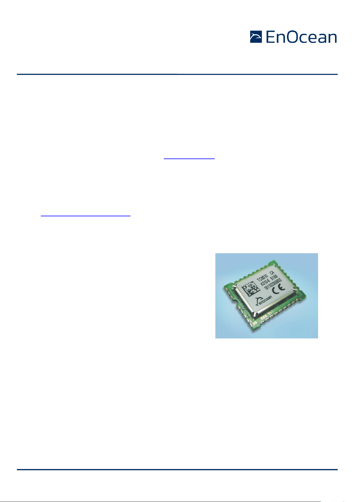
TCM 410J – Transceiver Gateway Module
© 2020 EnOcean | www.enocean.com TCM 410J User Manual | v2.2 | Dec 2020 | Page 1/ 41
TCM 410J – Transceiver Gateway Module
Patent protected:
WO98/36395, DE 100 25 561, DE 101 50 128,
WO 2004/051591, DE 103 01 678 A1, DE 10309334,
WO 04/109236, WO 05/096482, WO 02/095707,
US 6,747,573, US 7,019,241
Observe precautions! Electrostatic sensitive devices!
Page 2

USER MANUAL
TCM 410J – Transceiver Module
© 2020 EnOcean | www.enocean.com TCM 410J User Manual | v2.2 | Sep 2020 | Page 2 / 41
REVISION HISTORY
The following major modifications and improvements have been made to the first version of
this document:
No
Major Changes
1.00
Initial version
1.10
Added certification information and PCB Design
1.2
Changed power support information
1.3
Updated Energy consumption. Added example circuits for reset and prog_en pins.
Extended PIN description. Added IOVDD and PINs circuits when using dee psleep.
2.0
Module revision update, added enhanced security mode,
MSL4 -> MSL 3 and type approval updated.
2.1
Corrected Smart Ack Mailbox count and added description for repeating after POR
2.2
Update of ARIB regulations.
Published by EnOcean GmbH, Kolpingring 18a, 82041 Oberhaching, Germany
www.enocean.com, info@enocean.com, phone +49 (89) 6734 6890
© EnOcean GmbH
All Rights Reserved
Important!
This information describes the type of component and shall not be considered as assured characteristics. No responsibility is assumed for possible omissions or inaccuracies. Circuitry and specifications
are subject to change without notice. For the latest product specifications, refer to the EnOcean website: http://www.enocean.com.
As far as patents or other rights of third parties are concerned, liability is only assumed for modules,
not for the described applications, processes and circuits.
EnOcean does not assume responsibility for use of modules described and limits its liability to the
replacement of modules determined to be defective due to workmanship. Devices or systems containing RF components must meet the essential requirements of the local legal authorities.
The modules must not be used in any relation with equipment that supports, directly or indirectly,
human health or life or with applications that can result in danger for people, animals or real value.
Components of the modules are considered and should be disposed of as hazardous waste. Local
government regulations are to be observed.
Packing: Please use the recycling operators known to you.
Page 3

USER MANUAL
TCM 410J – Transceiver Module
© 2020 EnOcean | www.enocean.com TCM 410J User Manual | v2.2 | Sep 2020 | Page 3 / 41
TABLE OF CONTENT
1. MODULE VARIANTS AND RELATED DOCUMENTS ............................................... 5
2. GENERAL DESCRIPTION ................................................................................. 5
2.1 Basic functionality ......................................................................................... 5
2.2 Technical data ............................................................................................... 7
2.3 Physical dimensions ....................................................................................... 7
2.4 Environmental conditions ............................................................................... 8
2.5 Ordering information ..................................................................................... 8
2.6 References ................................................................................................... 8
3. FUNCTIONAL DESCRIPTION ............................................................................ 9
3.1 Pin out ......................................................................................................... 9
3.2 Pin description and operational characteristics ................................................ 10
3.2.1 GPIO supply voltage - IOVDD .................................................................... 11
3.2.2 Handling IOVDD and PINs with sleep mode ................................................. 11
3.3 Absolute maximum ratings (non operating) .................................................... 12
3.4 Maximum ratings (operating) ........................................................................ 12
3.5 Suggested RESET and PROG_EN circuitry ....................................................... 13
3.6 System environment .................................................................................... 13
3.7 Serial Interface ........................................................................................... 15
3.8 Built-in Repeater ......................................................................................... 16
3.9 Smart Acknowledge ..................................................................................... 17
3.10 Remote Management .............................................................................. 17
3.11 Serial communication with TYPE 01 or TYPE 10 .......................................... 17
3.12 Module configuration ............................................................................... 18
4. SECURITY DETAILS ..................................................................................... 18
4.1 Operational modes ...................................................................................... 19
4.1.1 Inbound communication – Teach-in & Data ............................................. 19
4.1.1.1 Resynchronisation of Taught In Secure Devices .................................... 21
4.1.1.2 Decoding Telegrams in detail .............................................................. 21
4.1.1.3 Filtering ........................................................................................... 22
4.1.2 Outbound communication – Teach-in & Data ........................................... 23
4.1.2.1 Teach In .......................................................................................... 23
4.1.2.2 Data communication.......................................................................... 23
4.2 Storage for Rolling Codes and Keys ............................................................... 24
4.2.1 Possible external memories ................................................................... 25
4.2.2 Voltage drops ...................................................................................... 26
4.3 Configurations ............................................................................................ 26
5. APPLICATIONS INFORMATION....................................................................... 28
5.1 Transmission range ..................................................................................... 28
5.2 Antenna options .......................................................................................... 28
5.2.1 Overview ................................................................................................ 28
5.2.2 Whip antenna ......................................................................................... 28
5.2.3 Helical antenna ....................................................................................... 29
5.2.4 Top loaded PCB spiral antenna .................................................................. 30
5.3 Recommendations for laying a whip antenna .................................................. 32
5.4 Power supply requirements ........................................................................... 33
5.5 Layout recommendations ............................................................................. 33
5.5.1 Recommended foot pattern ....................................................................... 34
5.6 Soldering information .................................................................................. 37
Page 4

USER MANUAL
TCM 410J – Transceiver Module
© 2020 EnOcean | www.enocean.com TCM 410J User Manual | v2.2 | Sep 2020 | Page 4 / 41
5.7 Tape & Reel specification .............................................................................. 38
6. AGENCY CERTIFICATIONS ............................................................................ 39
6.1 Japanese Type Approval ............................................................................... 39
Page 5
USER MANUAL
TCM 410J – Transceiver Module
© 2020 EnOcean | www.enocean.com TCM 410J User Manual | v2.2 | Sep 2020 | Page 5 / 41
1. MODULE VARIANTS AND RELATED DOCUMENTS
This document describes operation of TCM 410J module with the frequency 928.35 MHz.
Subject of description is the:
build in software Dolphin V4 Decoding Gateway – short: DolphinV4 GWC S.
used hardware TCM 410J
In the Document we refer to the Hardware and Software characteristic by the module name
TCM 410J.
In addition we recommend following our application notes, in particular
AN101: Power Supply Layout – Layout considerations for Line-Power
AN102: Antenna Basics – Basic Antenna Design Considerations for EnOcean based
Products
The specification of the serial protocol ESP3 can be found here:
http://www.enocean.com/esp
2. GENERAL DESCRIPTION
2.1 Basic functionality
TCM 410J is a SMD mountable radio transmitter module enabling the realization of gateways for EnOcean
928.35 MHz radio systems. It provides a bi-directional
radio interface and a bi-directional serial interface.
Radio messages are sent transparently through the
serial interface in both directions from and to an externally connected host processor or host PC. On demand the outgoing radio communication can be encrypted & incoming radio communication can be decrypted by the TCM 410J module. In addition control
commands can be sent from the host, e.g. to configure
the repeater functionality or to manage Smart Ack
functions. TCM 410J can act as postmaster for up to 15 bi-directional sensors using Smart
Ack technology.
Features
Smart Ack controller functionality
Transparent radio channel
Programmable repeater functionality (1 Level)
ESP3 support (EnOcean Serial Protocol V3)
Enhanced security communication
API programmable!
Page 6

USER MANUAL
TCM 410J – Transceiver Module
© 2020 EnOcean | www.enocean.com TCM 410J User Manual | v2.2 | Sep 2020 | Page 6 / 41
Security features:
Decodes secured telegrams
Encodes telegrams into secured telegrams
Handling and storing Rolling Codes and Security Keys
- For outgoing communication
- For ingoing communication
I2C Implementation to communicate with external EEPROM
Attack detection
Configurable security parameters (RLC Window, etc.)
Page 7
USER MANUAL
TCM 410J – Transceiver Module
© 2020 EnOcean | www.enocean.com TCM 410J User Manual | v2.2 | Sep 2020 | Page 7 / 41
2.2 Technical data
Features overview
Antenna
External whip or 50Ω antenna mountable
Frequency
928.35 MHz (FSK)
Radio Standard
Enocean Radio Protocol 2 (FSK)
Data rate/Modulation type
125 kbps FSK
Receiver Sensitivity (at 25°C)
typ. –95 dBm
Conducted Output Power
typ. 0dBm
Power Supply
2.6…5V
Serial Interface
UART - EnOcean Serial Protocol 3
Current Consumption
Receive mode (incl. CPU current): 27 mA
Transmit mode (incl. CPU current): 22 mA
Dimensions of PCB
22x19x3.1 mm
Operating temperature
-25 to +85°C
Radio Regulations
ARIB STD-T108
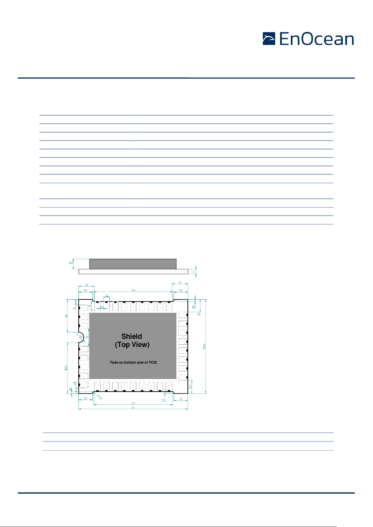
2.3 Physical dimensions
TCM 410J (pads on bottom side of PCB!)
PCB Dimension 22 x 19 x 3.1 mm
Weight 1.9 g
Unless otherwise specified dimensions are in mm.
Tolerances:
PCB outline dimensions 0.2 mm
All other tolerances 0.1 mm
Page 8

USER MANUAL
TCM 410J – Transceiver Module
© 2020 EnOcean | www.enocean.com TCM 410J User Manual | v2.2 | Sep 2020 | Page 8 / 41
2.4 Environmental conditions
Operating temperature -25 °C … +85 °C
Storage temperature -40 °C … +85 °C
Storage temperature in tape & reel package -20 °C … +50 °C
Humidity 0% … 93% r.H., non-condensing
2.5 Ordering information
Type
Ordering Code
Frequency
TCM 410J
S3063-K410
928.35 MHz
2.6 References
1. EnOcean Radio Standard Specifications -
https://www.enocean-alliance.org/what-is-enocean/specifications/
2. EnOcean Serial Protocol v3.0 -
https://www.enocean.com/esp
3. EnOcean Tools -
https://www.enocean.com/en/knowledge-base/
Page 9
USER MANUAL
TCM 410J – Transceiver Module
© 2020 EnOcean | www.enocean.com TCM 410J User Manual | v2.2 | Sep 2020 | Page 9 / 41
3. FUNCTIONAL DESCRIPTION
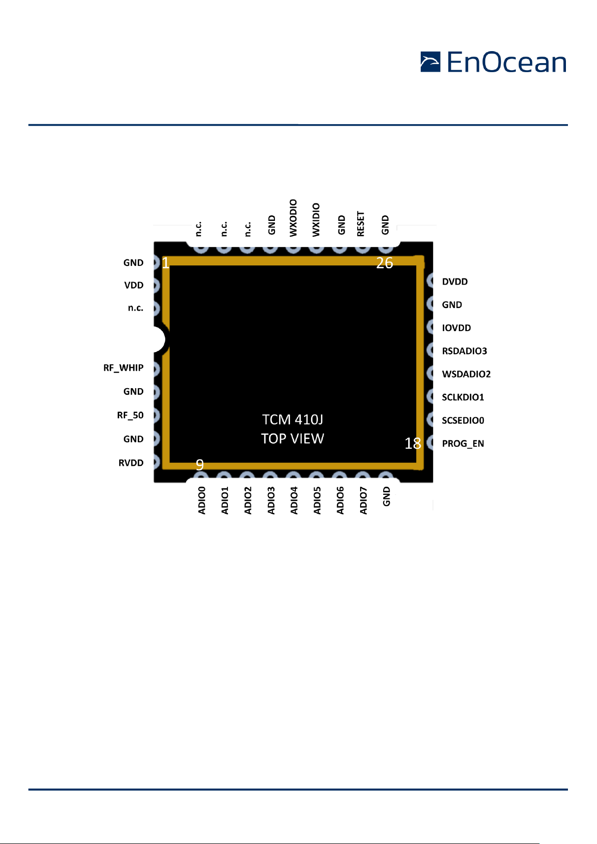
3.1 Pin out
The figure above shows the pin out of the TCM 410J hardware. The pins are named according to the naming of the Dolphin chip to simplify usage of the DOLPHIN API 2.
The table in section 0 shows the translation of hardware pins to a naming that fits the functionality of the built-in firmware..
Page 10

USER MANUAL
TCM 410J – Transceiver Module
© 2020 EnOcean | www.enocean.com TCM 410J User Manual | v2.2 | Sep 2020 | Page 10 / 41
3.2 Pin description and operational characteristics
HW Symbol
Pin #
Function
Characteristics
GND
1, 5, 7,
17, 24,
26, 28, 31
Ground connection
Must be connected to GND; see 5.4
VDD
2
Supply voltage
2.6 V … 5 V
RVDD
8
RF supply voltage regulator
output
Leave open
DVDD
25
Digital supply voltage
regulator output
1.8 V
Output current: max. 5 mA
IOVDD
23
GPIO supply voltage
Must be connected to desired interface supply voltage (see 3.4) See also
3.2.1.
RESET
27
Reset input
Programming I/F
Active high reset. External 10 kΩ pulldown parallel to 10nF capacitor recommended. See 3.5.
PROG_EN
18
Digital input,
Programming I/F
HIGH (at start up): programming
mode active
LOW: operating mode
External 10 kΩ pull-down parallel to
10nF capacitor recommended. See
3.5.
ADIO0
9
Not used by standard FW.
Configured as Digital In with Pull Up
ADIO1
10
Not used by standard FW.
Configured as Digital In with Pull Up
ADIO2
11
Not used by standard FW.
Configured as Digital In with Pull Up
ADIO3
12
Not used by standard FW.
Configured as Digital In with Pull Up
ADIO4
13
Not used by standard FW.
Configured as Digital In with Pull Up
ADIO5
14
Not used by standard FW.
Configured as Digital In with Pull Up
ADIO6
15
UART input – RX
See 0
ADIO7
16
UART output - TX
Programming I/F
See 0
SCSEDIO0
19
Interface for external
EEPROM with I2C interface
Programming I/F
Digital I/O for I2C Data communication.
SCLKDIO1
20
Interface for external
EEPROM with I2C interface.
Programming I/F
Digital Output, Clock pin for I2C
Communication
WSDADIO2
21
Not used by standard FW.
Programming I/F
Configured as Digital In with Pull Up
RSDADIO3
22
Not used by standard FW.
Programming I/F
Configured as Digital In with Pull Up
WXIDIO
29
Not used by standard FW.
Configured as Digital In with Pull Up
WXODIO
30
Not used by standard FW.
Configured as Digital In with Pull Up
RF_WHIP
4
RF output
Output for whip antenna
RF_50
6
RF output
50 Ohm output for external antenna
Page 11
USER MANUAL
TCM 410J – Transceiver Module
© 2020 EnOcean | www.enocean.com TCM 410J User Manual | v2.2 | Sep 2020 | Page 11 / 41
n.c.
3, 32,33,
34
Not connected
Do not connect!
3.2.1 GPIO supply voltage - IOVDD
For digital communication with other circuitry (peripherals) the digital I/O configured pins
of the mixed signal sensor interface (ADIO0 to ADIO7) and the pins of the serial interface
(SCSEDIO0, SCLKDIO1, WSDADIO2, RSDADIO3) may be operated from supply voltages
different from DVDD. Therefore an interface voltage supply pin IOVDD is available which
must be connected either to DVDD or to an external supply within the tolerated voltage
range of IOVDD.
If DVDD=0 V (e.g. in any sleep mode or if VDD<VOFF) and IOVDD is supplied,
there may be unpredictable and varying current from IOVDD caused by internal
floating nodes. It must be taken care that the current into IOVDD does not exceed
10 mA while DVDD=0 V.
If DVDD=0 V and IOVDD is not supplied, do not apply voltage to any above mentioned pin. This may lead to unpredictable malfunction of the device.
For I/O pins configured as analogue pins the IOVDD voltage level is not relevant!
However it is important to connect IOVDD to a supply voltage as specified in 3.4.
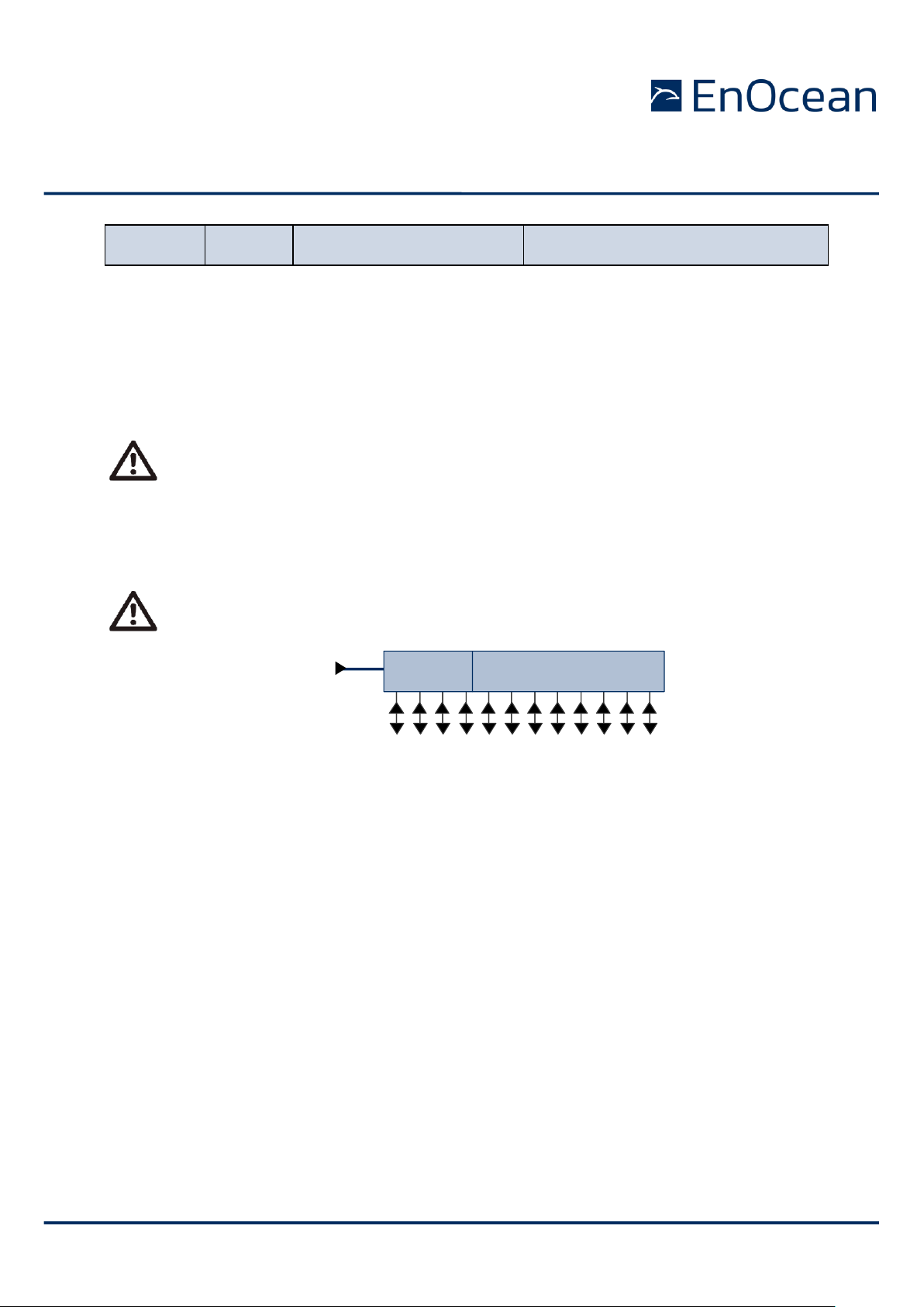
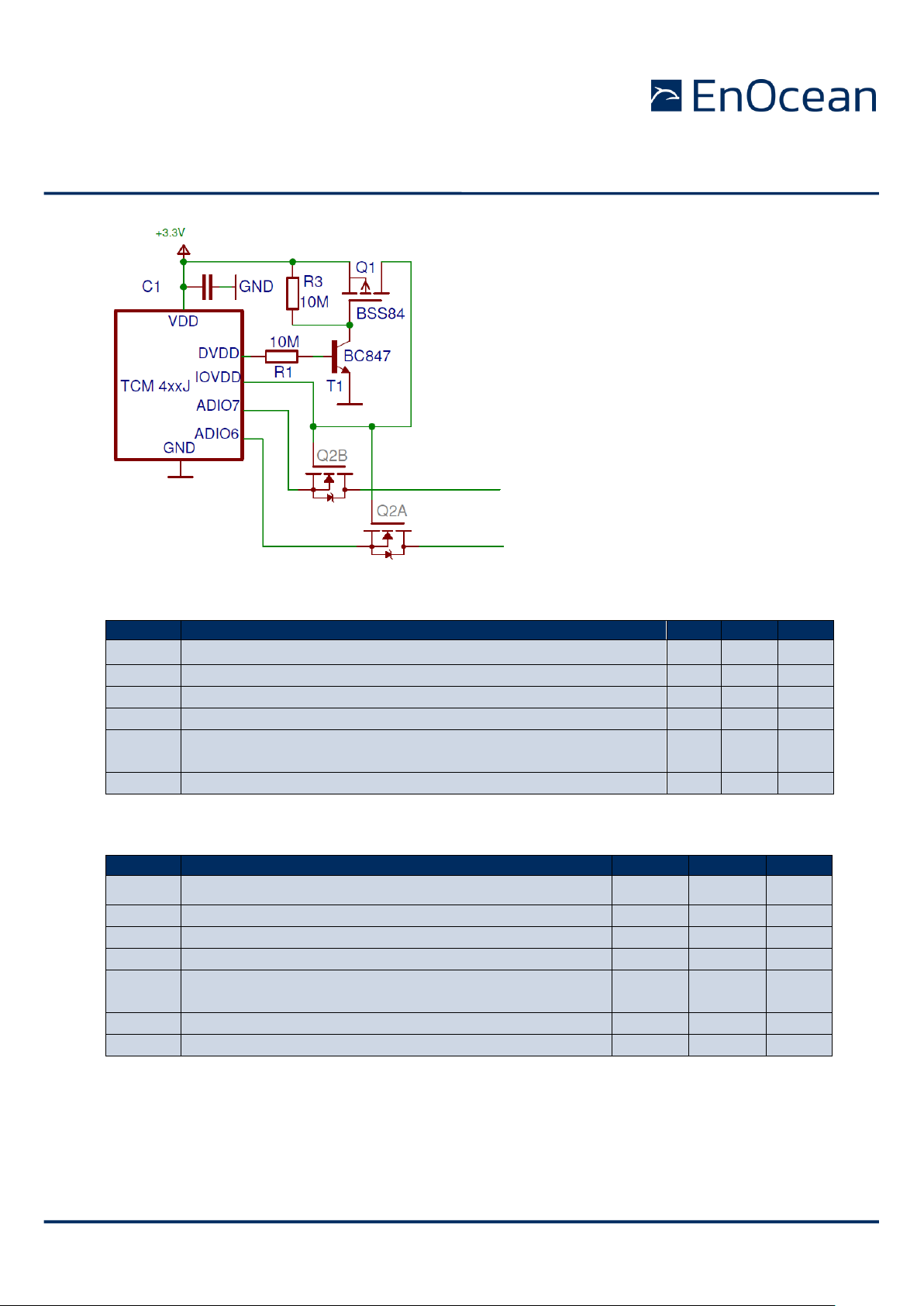
3.2.2 Handling IOVDD and PINs with sleep mode
TCM 410J is aimed for line powered applications to communicate over UART. But sometimes it is desirable to put the device into sleep mode. As stated in chapter 3.2.1. it is not
recommended to supply IOVDD or connect voltage to IOs if DVDD = 0 V (e.g. in any sleep
mode or if VDD<VOFF).
If the module is put into deep sleep mode (i.e. with the serial command CO_WR_SLEEP,
see chapter 0) it is important to respect above statement and cut IOVDD supply and do not
apply voltage on IOs. The IOs concern mostly the UART interface
The following example applies to cut the IOVDD from supply and IO by the DVDD as controlling signal.
IOVDD
ADIO0
ADIO1
ADIO2
ADIO3
ADIO4
ADIO5
ADIO6
ADIO7
SCSEDIO0
SCLKDIO1
WSDADIO2
RSDADIO3
If configured as digital I/O
Page 12
USER MANUAL
TCM 410J – Transceiver Module
© 2020 EnOcean | www.enocean.com TCM 410J User Manual | v2.2 | Sep 2020 | Page 12 / 41
3.3 Absolute maximum ratings (non operating)
Symbol
Parameter
Min
Max
Units
VDD
Supply voltage at VDD
-0.5
5.5
V
IOVDD
GPIO supply voltage
-0.5
3.6
V
GND
Ground connection
0 0 V
VINA
Voltage at every analog input pin
-0.5 2 V
VIND1
Voltage at RESET, and every digital input pin except
WXIDIO/WXODIO
-0.5
3.6
V
VIND2
Voltage at WXIDIO / WXODIO input pin
-0.5 2 V
3.4 Maximum ratings (operating)
Symbol
Parameter
Min
Max
Units
VDD
Supply voltage at VDD
2.6 5 V
IOVDD
GPIO supply voltage (see also 3.2.1)
1.7
3.6
V
GND
Ground connection
0 0 V
VINA
Voltage at every analog input pin
0
2.0
V
VIND1
Voltage at RESET, and every digital input pin except
WXIDIO / WXODIO
0
3.6
V
VIND2
Voltage at WXIDIO / WXODIO input pin
0
2.0
V
VDDR
Max. ripple at VDD
50
mVpp
Page 13
USER MANUAL
TCM 410J – Transceiver Module
© 2020 EnOcean | www.enocean.com TCM 410J User Manual | v2.2 | Sep 2020 | Page 13 / 41
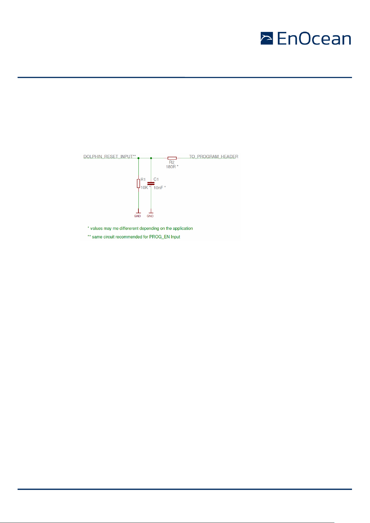
3.5 Suggested RESET and PROG_EN circuitry
In order to ensure reliable operation it is recommended to connect both the RESET and the
PROG_EN with a 10 kΩ resistor in parallel with a 10 nF capacitor to ground. This avoids
spurious signal detection in very noisy environments and in situations where an external
programming header is provided.
The suggested circuit is shown below.
If the programming interfaces / reset line is not used then the TO_PROGRAM_HEADER line
should be put to GND.
3.6 System environment
In the figure below, TCM 410J is shown in a typical system environment.
Page 14

USER MANUAL
TCM 410J – Transceiver Gateway Module
© 2020 EnOcean | www.enocean.com TCM 410J User Manual | v2.2 | Dec 2020 | Page 14/ 41
Radio
Gateway
ESP3
Backbone
or
PC
external
µ
C
TCM410J
Smart
Ack
Sensor
STM400J
With
API
Smart
Ack
Radio
Gateway
ext
.
µ
C
ESP3
TCM410J
Back
-
bone
or
PC
Smar
Ack
Remote management
Transparent radio
Unidirectional
Sensor or
PTM 210J, STM4xyJ
Uni or bidirectional
Actuator
e.g. TCM 410J
Switch e.g.
Page 15

USER MANUAL
TCM 410J – Transceiver Gateway Module
© 2020 EnOcean | www.enocean.com TCM 410J User Manual | v2.2 | Dec 2020 | Page 15/ 41
3.7 Serial Interface
TCM 410J provides a bi-directional serial interface which conforms to the EnOcean ESP3
specification. For details regarding ESP3 please refer to the ESP3 specification1. The data
rate on the serial interface is 56.8 kbit/s which is usually interoperable with systems running at 57.6 kbit/s.
Direction
Nominal serial data rate
Tolerance
TX (sent by module)
56888 bit/s (=57600 bit/s - 1.23%)
< 50 ppm
RX (received by module)
56888 bit/s
< 5%
The following ESP3 commands are supported:
Type 1 Radio command for transparent mode (compatible mode)
Type 10 Radio command for transparent mode (native mode)
Type 2 Responses
Type 4 Event
o SA_CONFIRM_LEARN to confirm/discard learn in/out
o CO_READY to indicate wake up from deep sleep initiated by CO_WR_SLEEP
Type 5 Common commands
o CO_WR_SLEEP to enter energy saving mode (deep sleep mode)
o CO_WR_RESET to reset the device
o CO_RD_VERSION to read SW/HW versions, chip ID etc.
o CO_WR_BIST to perform flash BIST operation
o CO_WR_IDBASE to write ID range base number
o CO_RD_IDBASE to read ID range base number
o CO_WR_REPEATER to configure repeater functionality
o CO_RD_REPEATER to read repeater state
o CO_WR_FILTER_ADD to add filter to filter list (up to 10 filters are supported)
o CO_WR_FILTER_DEL to delete filter from filter list
o CO_WR_FILTER_DEL_ALL to delete all filter
o CO_WR_FILTER_ENABLE to enable/disable supplied filters
o CO_RD_FILTER to read supplied filters
o CO_WR_WAIT_MATURITY to wait maturity time before returning radio telegrams
o CO_WR_MODE - Sets the gateway transceiver mode, either packet type 01 or pack-
et type 10
Type 6 Smart Acknowledge commands
o SA_WR_LEARNMODE to set/reset Smart Acknowledge learn mode
o SA_RD_LEARNMODE to get learn mode
o SA_WR_LEARNCONFIRM to add or delete a mailbox of a client
o SA_WR_RESET to send a reset command to a client
o SA_RD_LEARNEDCLIENTS to get learned mailboxes/clients
o SA_WR_POSTMASTER to activate/deactivate post master functionality
Type 7 Remote Management messages up to 256 Bytes
1
http://www.enocean.com/en/enocean_modules/tcm-310/
Page 16

USER MANUAL
TCM 410J – Transceiver Module
© 2020 EnOcean | www.enocean.com TCM 410J User Manual | v2.2 | Sep 2020 | Page 16 / 41
Additionally these security tasks related commands are supported:
Type 5 Common commands
CO_WR_LEARNMODE
CO_RD_LEARNMODE
CO_WR_SECUREDEVICE_ADD
CO_WR_SECUREDEVICE_DEL
CO_RD_SECUREDEVICE_COUNT
CO_RD_SECUREDEVICE_BY_INDEX
CO_RD_SECUREDEVICE_BY_ID
CO_WR_SECUREDEVICE_SENDTEACHIN
CO_WR_SECUREDEVICE_ADD_PSK
CO_WR_TEMPORARY_RLC_WINDOW
Type 4 Event
CO_EVENT_SECUREDEVICES
This commands are NOT relevant to this Firmware and they are also not supported:
Type 5 Common commands
CO_RD_SECURITY
CO_WR_SECURITY
Due to storage limitations these commands are not longer supported:
Type 5 Common commands
CO_WR_MODE – Compatible mode
Type 1 Radio command for transparent mode (compatible mode)
3.8 Built-in Repeater
TCM 410J provides the option to activate a one level repeater for EnOcean radio telegrams.
1 Level Repeater, If a received telegram is a valid and original (not yet repeated), the telegram is repeated after a random delay.
For detailed recommendations regarding the usage of repeaters please refer to our application note EnOcean Wireless Systems - Installation Notes (PDF), 09/2010.
All configuration values set via ESP3 commands are held in RAM and will therefore
be lost after RESET or after a deep sleep phase. Only Smart Ack mailboxes are
stored in FLASH and are available also after RESET or a deep sleep phase.
After sending a CO_WR_RESET command, the following CO_READY event indi-
cates wake up reason 06 meaning ”A memory request from the CPU core does not
correspond to any valid memory location.” This is caused by the real reset cause
used when CO_WR_RESET will be performed. It is not a SW/HW malfunction.
The repeated telegram is marked as “repeated” by an increased repeater counter.
Configuration of the repeater is done via serial interface commands.
Page 17

USER MANUAL
TCM 410J – Transceiver Module
© 2020 EnOcean | www.enocean.com TCM 410J User Manual | v2.2 | Sep 2020 | Page 17 / 41
3.8.1 Persistent repeater settings after POR
The TCM 410J supports a configuration to either save the Repeater settings in volatile
memory (standard functionality) or non-volatile memory (extended functionality). The repeater settings are configured via the ESP3 command CO_WR_REPEATER. To enable the
extended functionality and configure the repeater to keep configuration also after a POR
please use the optional data field of the ESP 3 command.
The complete CO_WR_REPEATER command is defined as following:
Group
Offset
Size
Field
Value hex
Description
- 0 1
Sync. Byte
0x55
Header
1
2
Data Length
0x0003
3 bytes
3
1
Optional Length
0x00
0 byte
4
1
Packet Type
0x05
COMMON_COMMAND = 5
- 5 1
CRC8H
0xnn
Data
6
1
COMMAND Code
0x09
CO_WR_REPEATER = 09
7
1
REP_ENABLE
0x00…0x02
Repeater
OFF = 0, ON all = 1, ON filtered = 2
8
1
REP_LEVEL
0x00…0x02
When Repeater OFF must be 0, when ON
then 1 for Level-1 , 2 for Level-2
Optional
Data
9
1
Store configuration
in non-volatile
memory
0x00 – 0x01
0x00 (or no optional data) = DO NOT
store configuration in non-volatile
0x01 = DO store configuration in nonvolatile
-
10
1
CRC8D
0xnn
3.9 Smart Acknowledge
TCM 410J provides a post master function with 10 mailboxes for sensors using Smart Ack
technology. For more information on smart acknowledge please refer to 1.
When teaching-in a device using Smart Acknowledge please take care to switch off
all TCM 4xyJ devices which are not continuously powered. Otherwise these TCM
4xyJ modules could be declared postmaster. As soon as the power supply is
switched off, a postmaster would be missing and Smart Acknowledge would not
work any longer!
3.10 Remote Management
TCM 410J provides a transparent radio channel also for remote management messages
with a message length of up to 256 bytes. This enables an external micro controller connected to TCM 410J to handle remote management request from external devices or to
control other devices via remote management. For more information on remote management please refer to 1.
3.11 Serial communication with TYPE 01 or TYPE 10
TCM 410J operates as transparent gateway so the received radio telegrams are forwarded
on as serial packets to external controller with type 01 or type 10. The mode can be
switched by the serial command CO_WR_MODE.
- Usage of Type 01 is for compatibility reasons (compatibility mode)
- Usage of Type 10 is native for the Radio Protocol of TCM 410J.
Page 18

USER MANUAL
TCM 410J – Transceiver Module
© 2020 EnOcean | www.enocean.com TCM 410J User Manual | v2.2 | Sep 2020 | Page 18 / 41
The scenario is depicted on the figure below.
For transmission requests from external controller to the TCM 410J both types can be used
at any time of the operation.
3.12 Module configuration
Configuration parameters will be stored in a non-volatile memory on the TCM 410J module.
The parameters will be changeable with the Dolphin Suite configuration. The following parameters will be adjustable:
- default mode selection – if serial message are forwarded with serial type 01
or serial type 10
- sniffer mode selection – puts module into sniffer mode, which is suiting for
network observation and evaluation
- baud rate selection
4. SECURITY DETAILS
Following Security Level Formats are supported:
Content Encryption:
o No data encryption
o VAES 128
o AES – CBC
Rolling code usage:
o No RLC usage
o 2 byte RLC
o 3 byte RLC
CMAC usage:
o No CMAC usage
o 3 byte CMAC
o 4 byte CMAC
Teach-in protection:
o Plain teach-in
Page 19

USER MANUAL
TCM 410J – Transceiver Module
© 2020 EnOcean | www.enocean.com TCM 410J User Manual | v2.2 | Sep 2020 | Page 19 / 41
o Teach in protected by PSK (pre-shared key)
Supported Security Tasks:
Decoding / Encoding
Validation CMAC
Handling RLC
For details on Security Tasks and Security Level Format please see reference 1.
4.1 Operational modes
The Decoding Gateway has two operational modes:
Teach in mode (inbound / outbound)
Gateway operational mode
For inbound and outbound communication the Dolphin V4 Decoding Gateway is maintaining
entries of security profiles records. A security profile is the combined information of KEY,
RLC and SLF. Inbound and outbound profiles are stored separately. By using commands
CO_WR_SECUREDEVICE_ADD
CO_WR_SECUREDEVICE_DEL
CO_RD_SECUREDEVICE_BY_INDEX
CO_RD_NUMSECUREDEVICES
CO_RD_SECUREDEVICE_BY_ID
The Direction (inbound / outbound) must be specified. When using command
CO_RD_SECUREDEVICE_BY_INDEX then please notice than for inbound and outbound have
separated indexes. Both start at 0.
The entries in the inbound table are unique referenced by:
Index in the storage
Sender ID of the device which is taught in
The entries in the outbound table are unique referenced by:
Index in the storage
One of possible Base Ids of Dolphin V4 Decoding Gateway – communication is
broadcast, Sender ID = Specified Base ID
or
The Chip ID of Dolphin V4 Decoding Gateway – communication is broadcast, Sender
ID = Chip ID
or
The Chip ID of the opposite device, in which the Dolphin V4 Gateway is taught in –
communication is unicast, Sender ID = Chip ID of Dolphin V4 Decoding Gateway,
Destination ID = Chip ID of the opposite device
Please consider to select the correct ID based on your use case when adding devices to the
outbound table with the serial command CO_WR_SECUREDEVICE_ADD.
4.1.1 Inbound communication – Teach-in & Data
In Figure 1 the processing of incoming radio telegrams is shown. Also the teach-in mode
and resynchronisation feature is shown. Please find more details in the text below.
Page 20

USER MANUAL
TCM 410J – Transceiver Module
© 2020 EnOcean | www.enocean.com TCM 410J User Manual | v2.2 | Sep 2020 | Page 20 / 41
Figure 1 Operational functions - decoding
For the Dolphin V4 Decoding Gateway to decode data telegrams from the transmitting device the security information included in a teach-in message must be received. For this
purpose also the Dolphin V4 Decoding Gateway must be put into LRN Mode with the correct
act Dolphin V4 Decoding
Is message from Taught
In device?
Is a security Teach In
Message?
Is Teach In Mode Active?
Is data message from Taught In
device?
Radio
Message
Received
Is Private key in message
matching with stored?
Update
stored
Rolling Code
Send Teach In
Message on
UART Interface
Remove
Message
Teach In new
Device
Send EVENT
to inform
wrong key
Send
Message
on UART
Decode Telegram
Wait for
antoehr
message
Is TeachIn protected
with PSK?
Was PSK
provided
before?
Fetch PSK.
and decode
TeachIn
Send EVENT to
infrom about
missing PSK
Remove
message
[NO]
[YES]
[NO]
[NO]
[YES]
[NO]
[YES]
[YES]
[NO]
[YES]
[NO]
[YES]
[NO]
[YES]
Page 21

USER MANUAL
TCM 410J – Transceiver Module
© 2020 EnOcean | www.enocean.com TCM 410J User Manual | v2.2 | Sep 2020 | Page 21 / 41
UART Command (CO_WR_LEARNMODE, CO_RD_LEARNMODE). If not in LRN mode, the
teach-in request is ignored. See reference 2 for details on serial command.
If the teach-in process is realized with PSK (pre-shared key) then it must be available at
teach-in time. The Dolphin V4 Decoding Gateway can be initialized with a PSK with an UART
command (CO_WR_SECUREDEVICE_ADD_PSK). See reference 2 for details on the serial
command.
After a successful teach-in process the whole teach-in message is passed as one serial
packet type 10 on the serial interface.
Once the security information of a transmitting device is know the Dolphin V4 Decoding
Gateway can decode all incoming data communication and forward it to the serial interface
as packet type 10. All other telegrams received (with additional secure features or not) are
also forwarded to the serial interface. During operation mode the Dolphin V4 Decoding
gateway behaves as the Gateway Controller.
4.1.1.1 Resynchronisation of Taught In Secure Devices
During operating mode (not teach-in mode) teach in requests from unknown devices are
ignored. If a taught in device sends a teach-in request, the RLC code information is updated. This is aimed for the case where the receiver and sender’s RLC becomes desynchronized. The DolphinV4 Decoding Gateway also checks if the private key is matching. If not, it
may be a potential attack and the Decoding Gateway sends a CO_EVENT_SECUREDEVICES
for your information. See reference 2 for details on serial command.
If the resynchronization request is protected by the PSK then it must be present at the Dolphin V4 Gateway.
4.1.1.2 Decoding Telegrams in detail
In Figure 2 the decoding process is shown in detail. Please notice these two important features:
Temporary RLC window extension
For special purpose (e.g. power-up after long term power drop) the rolling code can
be extended for one telegram to enable user-friendly RLC resynchronization. The
Dolphin V4 Decoding Gateway will apply this temporary window for every taught-in
device but only one time for every devices next incoming telegram. To set or unset
the Temporary RLC window a serial command is specified
(CO_WR_TEMPORARY_RLC_WINDOW). See reference 2 for details on serial command.
Security RLC window – amount of failed CMAC validation attempts
This value defines the count of the wrong CMAC validation attempts, before the Dolphin V4 Decoding Gateway module sends the event serial command
(CO_EVENT_SECUREDEVICES). This event can signalize that a devices RLC is not
synchronized any more.
Page 22

USER MANUAL
TCM 410J – Transceiver Module
© 2020 EnOcean | www.enocean.com TCM 410J User Manual | v2.2 | Sep 2020 | Page 22 / 41
Figure 2 Decode telegram activities
4.1.1.3 Filtering
Data communication filtering is complete independent from inbound and outbound security
profiles lists. To filter incoming communication with the filter functionality on the Dolphin
V4 Decoding Gateway the common filter interface can be used, see also 2. To enable filter-
act Decode Telegram
Decoding
requested
Try to validate
CMAC within
normal RLC
window.
Is one time rolling window activated?
Try to validate CMAC
within one-time RLC
window.
Decoding succesfull?
Reset one-time
RLC - it wound get
used next time.
Increase security
window counter.
Has security window count
reached maximum?
Prepare
message for
serial
interface.
Reset
security
window
counter.
Proces
further
Send event, that
security window
reached.
[NO] [YES]
[NO]
[YES]
[NO]
[YES]
Page 23

USER MANUAL
TCM 410J – Transceiver Module
© 2020 EnOcean | www.enocean.com TCM 410J User Manual | v2.2 | Sep 2020 | Page 23 / 41
ing of inbound security profiles they have to be added to the list by the external Controller
by a serial command (e.g. CO_WR_FILTER_ADD) as any other device. See reference 2 for
details on serial command for filtering function.
It is not mandatory to use the filter interface. The Dolphin V4 Decoding Gateway has 60
filters available. The filters information is not stored in non-volatile memory. After module
restart the filters have to be set again.
4.1.2 Outbound communication – Teach-in & Data
4.1.2.1 Teach In
Before the Dolphin V4 Decoding Gateway can encrypt outgoing communication the SLF
format, KEY and RLC of the outgoing communication must be specified. The Dolphin V4
Decoding Gateway can have several outgoing communication profiles.
To add a secure device the command serial command CO_WR_SECUREDEVICE_ADD is
specified. See reference 2 for details on serial command.
To complete the security teach-in process the Dolphin V4 Decoding Gateway has to send a
security teach-in telegram to the other communication partner and so inform him about the
used security profile. To trigger the transmission of the teach-in telegram the serial command CO_WR_SECUREDEVICE_SENDTEACHIN is specified. See reference 2 for details on
serial command. In CO_WR_SECUREDEVICE_SENDTEACHIN command an ID reference
must be specified. Prior teach-in the entry with this ID must be added into the outbound
table. Please chapter 4.1 for details on ID reference.
If you would like to use PSK protection of the send teach-in request, then please specify it
respectively in the Optional Field – TeachInInInfo of the command
CO_WR_SECUREDEVICE_SENDTEACHIN. The PSK for all outgoing protection is same and
only readable and changeable trough Dolphin Suite 3.
If bidirectional teach-in should be performed please specify this also in the TeachInInInfo
field. Please find more details on the TeachInInInfo also in the Security specification reference 1
4.1.2.2 Data communication
In data communication it is sufficient to specify the correct reference ID in the Destination
ID field or Source ID field and the Dolphin V4 Decoding Gateway will automatically encrypt
the data communication. Please find details on outbound data communication in Figure 3.
Page 24

USER MANUAL
TCM 410J – Transceiver Module
© 2020 EnOcean | www.enocean.com TCM 410J User Manual | v2.2 | Sep 2020 | Page 24 / 41
Figure 3 Encoding activities
4.2 Storage for Rolling Codes and Keys
For security functionality the Gateway needs to store the following for each learned in de-
vice:
Security AES 128 key – 16 bytes
Rolling Code information – 2 or 3 bytes
The key is stored in the internal Dolphin V4 Chip and the RLC in an external EEPROM
memory.
act Dolphin V4 Encoding
Request to
transmitt
telegram
Is the telegram addressed?
Look up the
Destination
ID in the
Outbound
Table.
Look up the
Sender ID in
the Outbound
Table.
Enntry found?
Encrypt based
on the entrie's
SLF
Send out
radio
telegram
Serial
Message
Received
Continue
operation
[YES]
[NO]
[YES]
[NO]
Page 25

USER MANUAL
TCM 410J – Transceiver Module
© 2020 EnOcean | www.enocean.com TCM 410J User Manual | v2.2 | Sep 2020 | Page 25 / 41
Following maximum supported security profiles are possible:
30 outbound security profiles – devices
30 inbound security profiles - devices
The security Key of a device is constant. The RLC will change with every telegram transmission. Therefore the receiver needs to store it periodically during whole operational time. For
the case of power off the RLC needs to be store also in the non-volatile memory.
We define two storage frequency parameters – how often to store a RLC:
Outbound communication storage frequency – default every transmission
Inbound communication storage frequency – default every 30
th
transmission
Both parameters can be adjusted trough Dolphin Suite 3.
We used external memory for storage of rolling codes, because it ensures higher safety
through separating the rolling code storage place from program memory storage place and
enables a higher storage frequency.
4.2.1 Possible external memories
Decoding Gateway is used with external memory, we can refer to this possible EEPROM:
24AA08 Microchip – 8 kilobit.
As the Dolphin V4 Decoding Controller was developed using this module compatibility is
guaranteed. Based on the characteristics of the EEPROM module they can be connected
directly to the EnOcean Module. See example below:
Figure 4 EEPROM Connection
Page 26

USER MANUAL
TCM 410J – Transceiver Module
© 2020 EnOcean | www.enocean.com TCM 410J User Manual | v2.2 | Sep 2020 | Page 26 / 41
Please check second source memory modules for compatibility before use. Chang-
es in the Dolphin V4 Decoding Gateway I2C interface may be required.
4.2.2 Voltage drops
During critical tasks, in particular erasing a page, it must be ensured that enough power is
available. A power drop during this operation can cause unexpected behavior. Therefore we
recommend attaching an external capacitor to overcome a sudden power drop.
In case of EEPROM usage as Rolling Code Storage a small capacitor is needed – erase
time takes 5 ms @ 0.1 mA.
The storing of the KEY in the Dolphin V4 Chip memory is a one-time event executed only at
teach-in time. Due to low probability of failure at this time no additional measures were
taken.
4.3 Configurations
The security configurable values are stored in CFG Area. You can change them with Dolphin
Suite. The following parameters are available:
Security RC storage cycle outbound – Address in CFG: 0x23 Default value: 1
This value defines how many telegrams of one security profile will be send prior to updating the rolling code in persistent memory.
Security RC storage cycle inbound – Address in CFG: 0x22 (Length: 1 byte), Default val-
ue: 30
This value defines how many telegrams of one security profile will be send prior to updating the rolling code in persistent memory.
Wrong CMAC count – Security RLC window – Address in CFG: 0x20 (Length: 1 byte),
Default value: 100
This value defines the count of the wrong CMAC validation attempts, before the Decoding Gateway module sends the event serial command (CO_EVENT_SECUREDEVICES).
RLC window – Address in CFG: 0x1C (Length: 4 bytes), Default value: 128
This value defines how big the Rolling Code window can be. The Rolling code window defines the amount of tries where the device tries to validate the RLC from a message.
PSK – Pre-shared key - Address in CFG: 0x1C (Length: 16 bytes), Default value: N/A –
set in production
The PSK which can used for outbound security teach-in.
Please see configuration window from Dolphin Suite as reference:
Page 27

USER MANUAL
TCM 410J – Transceiver Module
© 2020 EnOcean | www.enocean.com TCM 410J User Manual | v2.2 | Sep 2020 | Page 27 / 41
Page 28

USER MANUAL
TCM 410J – Transceiver Module
© 2020 EnOcean | www.enocean.com TCM 410J User Manual | v2.2 | Sep 2020 | Page 28 / 41
5. APPLICATIONS INFORMATION
5.1 Transmission range
The main factors that influence the system transmission range are type and location of the
antennas of the receiver and the transmitter, type of terrain and degree of obstruction of
the link path, sources of interference affecting the receiver, and “dead” spots caused by
signal reflections from nearby conductive objects. Since the expected transmission range
strongly depends on this system conditions, range tests should categorically be performed
before notification of a particular range that will be attainable by a certain application.
The following figures for expected transmission range are considered by using a PTM, a
STM or a TCM radio transmitter device and the TCM radio receiver device with preinstalled
whip antenna and may be used as a rough guide only:
Line-of-sight connections: Typically 30 m range in corridors, up to 100 m in halls
Plasterboard walls / dry wood: Typically 30 m range, through max. 5 walls
Ferro concrete walls / ceilings: Typically 10 m range, through max. 1 ceiling
Fire-safety walls, elevator shafts, staircases and supply areas should be considered as
screening.
The angle at which the transmitted signal hits the wall is very important. The effective wall
thickness – and with it the signal attenuation – varies according to this angle. Signals
should be transmitted as directly as possible through the wall. Wall niches should be avoided. Other factors restricting transmission range:
Devices mounted on metal surfaces (shielding and detuning of antenna may cause heavy
loss of transmission range)
Hollow lightweight walls filled with insulating wool on metal foil
Suspended ceilings with panels of metal or carbon fibre
Lead glass or glass with metal coating, steel furniture
The distance between EnOcean receivers and other transmitting devices such as computers, audio and video equipment that also emit high-frequency signals should be at least 0.5
m
A summarized application note to determine the transmission range within buildings is
available as download from www.enocean.com.
5.2 Antenna options
5.2.1 Overview
Several antenna types have been investigated by EnOcean. Please refer to our application
notes AN102, and AN105 which give an overview on our recommendations.
5.2.2 Whip antenna
928.35 MHz
Antenna: 64 mm wire, connect to RF_WHIP
Page 29

USER MANUAL
TCM 410J – Transceiver Module
© 2020 EnOcean | www.enocean.com TCM 410J User Manual | v2.2 | Sep 2020 | Page 29 / 41
Minimum GND plane: 50 mm x 50 mm
Minimum distance space: 10 mm
Positioning and choice of receiver and transmitter antennas are the most important factors
in determining system transmission range.
For good receiver performance, great care must be taken about the space immediately
around the antenna since this has a strong influence on screening and detuning the antenna. The antenna should be drawn out as far as possible and must never be cut off. Mainly
the far end of the wire should be mounted as far away as possible (at least 15 mm) from all
metal parts, ground planes, PCB strip lines and fast logic components (e.g. microprocessors).
Do not roll up or twist the whip antenna!
Radio frequency hash from the motherboard desensitizes the receiver. Therefore:
PCB strip lines on the user board should be designed as short as possible
A PCB ground plane layer with sufficient ground vias is strongly recommended
5.2.3 Helical antenna
928.35 MHz
according to drawing below, connect to RF_WHIP
Minimum GND plane: 35 mm x 30 mm
Minimum distance space: 10 mm
Page 30

USER MANUAL
TCM 410J – Transceiver Module
© 2020 EnOcean | www.enocean.com TCM 410J User Manual | v2.2 | Sep 2020 | Page 30 / 41
5.2.4 Top loaded PCB spiral antenna
The design of the antenna made on a 1mm thick, two layer FR4 PCB. The dimensions are
given in figure below. The hatched areas are double sided in layout. The large area to the
left is a ground area. Components can be placed here as long as the area is not split by this
nor has long cuts in it which can act as radiators its self.
Dimensions of the PCB antenna.
Parameter of PCB
VALUE
PCB material
FR4, 2 layer
Thickness (total)
1,27mm
Shape
Rectangular with millings
Dimension
19*48,55 mm
Layer
Thickness in µm
Exact description
Solder Mask
Solder resist
Top Layer
35
Cu, >35um after electroplating
Core
1200
Bottom Layer
35
Cu, >35um after electroplating
Solder Mask
Solder resist
Total
1270
The PCB antenna uses three discrete matching components. The position of these components can be seen in figure below.
Page 31

USER MANUAL
TCM 410J – Transceiver Module
© 2020 EnOcean | www.enocean.com TCM 410J User Manual | v2.2 | Sep 2020 | Page 31 / 41
Position of matching components
The antenna was matched to 50Ω input impedance at the feed point. A compromise for a
good matching when plugged into a laptop and when plugged to the end of a USB cable
was chosen. Several environments in the proximity of the antenna where also evaluated for
this compromise. The following table shows the values of the proposed components.
Component
Value
C1
3.3pF
L1
12nH
L2
12nH
0603 components where used for the antenna matching. For the capacitor general purpose
C0G capacitors with 5% tolerance are sufficient. The inductors should be wire wound inductors from the Würth WE-KI series or the Murata LQW series.
C1
L2
L1
Page 32

USER MANUAL
TCM 410J – Transceiver Module
© 2020 EnOcean | www.enocean.com TCM 410J User Manual | v2.2 | Sep 2020 | Page 32 / 41
5.3 Recommendations for laying a whip antenna
Antenna too close
to GND area
Antenna end led
back to foot point
PCB
with
GND
PCB
without
GND
Antenna
too
close
to GND
area
Page 33

USER MANUAL
TCM 410J – Transceiver Module
© 2020 EnOcean | www.enocean.com TCM 410J User Manual | v2.2 | Sep 2020 | Page 33 / 41
5.4 Power supply requirements
In order to provide a good radio performance, great attention must be paid to the power
supply and a correct layout and shielding. It is recommended to place a 22 µF ceramic capacitor between VDD and GND close to the module (material: X5R, X7R, min 6.3 V to avoid
derating effects).
In addition, an HF SMD EMI Suppression Ferrite Bead such as the Würth WE-CBF HF SMD
EMI Suppression Ferrite Bead (Würth order number 742863160) shall be inserted in the
power supply line.
For best performance it is recommended to keep the ripple on the power supply rail below
10 mVpp (see 3.4).
All GND pins must be connected to GND. Be careful not to create loops! The
ground must be realized ideally on both sides of the PCB board with many Vias. At
least there must be a short star connection. Otherwise RF performance can be
reduced!
5.5 Layout recommendations
The length of lines connected to I/Os should not exceed 5 cm.
It is recommended to have a complete GND layer in the application PCB, at least
in the area below the module and directly connected components (e.g. mid-layer
of your application PCB).
Due to unisolated test points there are live signals accessible on the bottom side
of the module.
Please follow the following advices to prevent interference with your application
circuit:
We suggest avoiding any copper structure in the area directly underneath
the module (top-layer layout of your application PCB). If this is not possible
in your design, please provide coating on top of your PCB to prevent short
circuits to the module. All bare metal surfaces including vias have to be
covered (e.g. adequate layout of solder resist).
It is mandatory that the area marked by the circle in the figure below is
kept clear of any conductive structures in the top layer and 0.3 mm below.
Otherwise RF performance will be degraded!
Furthermore, any distortive signals (e.g. bus signals or power lines) should not be
routed underneath the module. If such signals are present in your design, we suggest separating them by using a ground plane between module and these signal
lines.
Page 34

USER MANUAL
TCM 410J – Transceiver Module
© 2020 EnOcean | www.enocean.com TCM 410J User Manual | v2.2 | Sep 2020 | Page 34 / 41
5.5.1 Recommended foot pattern Top layer
Page 35

USER MANUAL
TCM 410J – Transceiver Module
© 2020 EnOcean | www.enocean.com TCM 410J User Manual | v2.2 | Sep 2020 | Page 35 / 41
Solder resist top layer
Page 36

USER MANUAL
TCM 410J – Transceiver Module
© 2020 EnOcean | www.enocean.com TCM 410J User Manual | v2.2 | Sep 2020 | Page 36 / 41
Solder paste top layer
The data above are also available as EAGLE library.
In order to ensure good solder quality a solder mask thickness of 150 µm is recommended.
In case a 120 µm solder mask is used, it is recommended to enlarge the solder print. The
pads on the solder print should then be 0.1 mm larger than the pad dimensions of the
module as specified in chapter 2.3. (not relative to the above drawing).
Nevertheless an application and production specific test regarding the amount of soldering
paste should be performed to find optimum parameters.
Page 37

USER MANUAL
TCM 410J – Transceiver Module
© 2020 EnOcean | www.enocean.com TCM 410J User Manual | v2.2 | Sep 2020 | Page 37 / 41
5.6 Soldering information
TCM 410J shall be soldered according to IPC/JEDEC J-STD-020C standard.
TCM 410J shall be handled according to Moisture Sensitivity Level MSL3 which means a
floor time of 168 h. TCM 410J may be soldered only once, since one time is already consumed at production of the module itself.
Once the dry pack bag is opened, the desired quantity of units should be removed and the
bag resealed within two hours. If the bag is left open longer than 30 minutes the desiccant
should be replaced with dry desiccant. If devices have exceeded the specified floor life time
of 72 h, they may be baked according IPC/JEDEC J-STD-033B at max. 90°C for less than
60 h.
Devices packaged in moisture-proof packaging should be stored in ambient conditions not
exceeding temperatures of 40 °C or humidity levels of 90% r.H.
TCM 410J modules shall be soldered within 6 months after delivery!
Page 38

USER MANUAL
TCM 410J – Transceiver Module
© 2020 EnOcean | www.enocean.com TCM 410J User Manual | v2.2 | Sep 2020 | Page 38 / 41
5.7 Tape & Reel specification
Tape running direction
Page 39

USER MANUAL
TCM 410J – Transceiver Module
© 2020 EnOcean | www.enocean.com TCM 410J User Manual | v2.2 | Sep 2020 | Page 39 / 41
6. AGENCY CERTIFICATIONS
The modules have been tested to fulfil the approval requirements based on the built-in
firmware.
When developing customer specific firmware based on the API for this
module, special care must be taken not to exceed the specified regulatory
limits, e.g. the duty cycle limitations!
Please find more details in the EnOcean Radio Protocol 2 Specification2.
6.1 Japanese Type Approval
TCM 410J complies with the Japanese radio law and is certified according to ARIB STDT108.
When the product is placed on the Japanese market, it must carry the Specified Radio
Equipment marking as shown below:
If the certification label cannot be recognized from outside (e.g. installation in a host) appropriate information must be referenced in the user manual.
2
https://www.enocean.com/fileadmin/redaktion/pdf/tec_docs/EnOceanRadioProtocol2.pdf
Page 40

USER MANUAL
TCM 410J – Transceiver Module
© 2020 EnOcean | www.enocean.com TCM 410J User Manual | v2.2 | Sep 2020 | Page 40 / 41
Page 41

USER MANUAL
TCM 410J – Transceiver Module
© 2020 EnOcean | www.enocean.com TCM 410J User Manual | v2.2 | Sep 2020 | Page 41 / 41
 Loading...